EP3449948B1 - Ozonzerstörende ultraviolettlichtreinigungssysteme und verfahren - Google Patents
Ozonzerstörende ultraviolettlichtreinigungssysteme und verfahren Download PDFInfo
- Publication number
- EP3449948B1 EP3449948B1 EP18185392.0A EP18185392A EP3449948B1 EP 3449948 B1 EP3449948 B1 EP 3449948B1 EP 18185392 A EP18185392 A EP 18185392A EP 3449948 B1 EP3449948 B1 EP 3449948B1
- Authority
- EP
- European Patent Office
- Prior art keywords
- light
- airflow
- airflow generator
- sanitizing
- light source
- Prior art date
- Legal status (The legal status is an assumption and is not a legal conclusion. Google has not performed a legal analysis and makes no representation as to the accuracy of the status listed.)
- Active
Links
Images


Classifications
-
- A—HUMAN NECESSITIES
- A61—MEDICAL OR VETERINARY SCIENCE; HYGIENE
- A61L—METHODS OR APPARATUS FOR STERILISING MATERIALS OR OBJECTS IN GENERAL; DISINFECTION, STERILISATION OR DEODORISATION OF AIR; CHEMICAL ASPECTS OF BANDAGES, DRESSINGS, ABSORBENT PADS OR SURGICAL ARTICLES; MATERIALS FOR BANDAGES, DRESSINGS, ABSORBENT PADS OR SURGICAL ARTICLES
- A61L2/00—Disinfection or sterilisation of materials or objects, in general; Accessories therefor
- A61L2/02—Disinfection or sterilisation of materials or objects, in general; Accessories therefor using physical processes
- A61L2/08—Radiation
- A61L2/10—Ultraviolet [UV] radiation
-
- A—HUMAN NECESSITIES
- A61—MEDICAL OR VETERINARY SCIENCE; HYGIENE
- A61L—METHODS OR APPARATUS FOR STERILISING MATERIALS OR OBJECTS IN GENERAL; DISINFECTION, STERILISATION OR DEODORISATION OF AIR; CHEMICAL ASPECTS OF BANDAGES, DRESSINGS, ABSORBENT PADS OR SURGICAL ARTICLES; MATERIALS FOR BANDAGES, DRESSINGS, ABSORBENT PADS OR SURGICAL ARTICLES
- A61L2/00—Disinfection or sterilisation of materials or objects, in general; Accessories therefor
- A61L2/24—Apparatus using programmed or automatic operation
-
- A—HUMAN NECESSITIES
- A61—MEDICAL OR VETERINARY SCIENCE; HYGIENE
- A61L—METHODS OR APPARATUS FOR STERILISING MATERIALS OR OBJECTS IN GENERAL; DISINFECTION, STERILISATION OR DEODORISATION OF AIR; CHEMICAL ASPECTS OF BANDAGES, DRESSINGS, ABSORBENT PADS OR SURGICAL ARTICLES; MATERIALS FOR BANDAGES, DRESSINGS, ABSORBENT PADS OR SURGICAL ARTICLES
- A61L2/00—Disinfection or sterilisation of materials or objects, in general; Accessories therefor
- A61L2/26—Accessories
-
- E—FIXED CONSTRUCTIONS
- E03—WATER SUPPLY; SEWERAGE
- E03D—WATER-CLOSETS OR URINALS WITH FLUSHING DEVICES; FLUSHING VALVES THEREFOR
- E03D9/00—Sanitary or other accessories for lavatories ; Devices for cleaning or disinfecting the toilet room or the toilet bowl; Devices for eliminating smells
- E03D9/002—Automatic cleaning devices
-
- A—HUMAN NECESSITIES
- A61—MEDICAL OR VETERINARY SCIENCE; HYGIENE
- A61L—METHODS OR APPARATUS FOR STERILISING MATERIALS OR OBJECTS IN GENERAL; DISINFECTION, STERILISATION OR DEODORISATION OF AIR; CHEMICAL ASPECTS OF BANDAGES, DRESSINGS, ABSORBENT PADS OR SURGICAL ARTICLES; MATERIALS FOR BANDAGES, DRESSINGS, ABSORBENT PADS OR SURGICAL ARTICLES
- A61L2103/00—Materials or objects being the target of disinfection or sterilisation
- A61L2103/75—Room floors or walls
-
- A—HUMAN NECESSITIES
- A61—MEDICAL OR VETERINARY SCIENCE; HYGIENE
- A61L—METHODS OR APPARATUS FOR STERILISING MATERIALS OR OBJECTS IN GENERAL; DISINFECTION, STERILISATION OR DEODORISATION OF AIR; CHEMICAL ASPECTS OF BANDAGES, DRESSINGS, ABSORBENT PADS OR SURGICAL ARTICLES; MATERIALS FOR BANDAGES, DRESSINGS, ABSORBENT PADS OR SURGICAL ARTICLES
- A61L2202/00—Aspects relating to methods or apparatus for disinfecting or sterilising materials or objects
- A61L2202/10—Apparatus features
- A61L2202/11—Apparatus for generating biocidal substances, e.g. vaporisers, UV lamps
-
- A—HUMAN NECESSITIES
- A61—MEDICAL OR VETERINARY SCIENCE; HYGIENE
- A61L—METHODS OR APPARATUS FOR STERILISING MATERIALS OR OBJECTS IN GENERAL; DISINFECTION, STERILISATION OR DEODORISATION OF AIR; CHEMICAL ASPECTS OF BANDAGES, DRESSINGS, ABSORBENT PADS OR SURGICAL ARTICLES; MATERIALS FOR BANDAGES, DRESSINGS, ABSORBENT PADS OR SURGICAL ARTICLES
- A61L2202/00—Aspects relating to methods or apparatus for disinfecting or sterilising materials or objects
- A61L2202/10—Apparatus features
- A61L2202/14—Means for controlling sterilisation processes, data processing, presentation and storage means, e.g. sensors, controllers, programs
Definitions
- Embodiments of the present disclosure generally relate to systems and methods for sanitizing surfaces with ultraviolet light, such as within lavatories of commercial aircraft, and, more particularly, to ozone-disrupting ultraviolet light sanitizing systems and methods.
- a typical commercial aircraft includes one or more lavatories within an internal cabin.
- UV light efficiently disinfects exposed surfaces within a lavatory.
- Ozone is an irritant, both to individuals and structures. For example, certain individuals may be susceptible to breathing disorders from prolonged exposure to ozone. Further, ozone is a reactive gas that may degrade surfaces of various structures.
- an FAA regulatory guideline limits the amount of ozone within an internal cabin of an aircraft to an average of 100 parts ozone per billion over an eight hour timeframe. Further, the FAA regulatory guideline also limits the amount of ozone within an internal cabin of an aircraft to 250 parts ozone per billion within a three hour peak timeframe.
- One known disinfecting method limits the amount of generated ozone by placing a steriliz ing UV light in close proximity to a surface that is to be sterilized.
- the UV light may be within one to six inches from a surface that is to be sterilized.
- the close proximity of the UV light to the surface limits ozone production, as the ozone travels through a shorter distance of ambient air.
- various structures are not able to be within such a close proximity to a UV light.
- a UV light may not be effectively positioned within a few inches of a toilet or floor within a lavatory.
- CN 104 873 994 A states a disinfecting and heating device for low-to-moderate-dangerousness medical equipment and a using method of the disinfecting and heating device.
- the disinfecting and heating device comprises a box body, a heater, an ultraviolet lamp and a bracket, wherein the box body is divided into a heating cavity and a disinfecting cavity which are communicated through an air outlet channel and an air return channel; the ultraviolet lamp and the bracket are arranged in the disinfecting cavity; the heater is arranged in the heating cavity; the air outlet channel is provided with a fan; the ultraviolet lamp has an ozone function.
- the medical equipment to be sterilized is arranged in the sterilizing cavity and is capable of keeping a warm state while rapid disinfection is realized, thus improving the comfort level of an inspected patient.
- a disinfecting holster for a bar gun includes a support surface configured to interface with a bar gun to support the bar gun when stowed in the holster, a housing coupled with the support surface and surrounding a dispensing nozzle of the bar gun when the bar gun is stowed in the holster, and an ultraviolet light source configured to emit germicidal ultraviolet light onto the nozzle.
- the housing substantially contains the ultraviolet light within the housing during the application of the ultraviolet light to the dispensing nozzle. The ultraviolet light can be periodically applied to maintain the nozzle in a disinfected state.
- US 9,144,618 B2 states sanitizing seat surfaces in a location being related to seating, such as a transportation vehicle includes a passenger area of the location. There are multiple rows of seats.
- a sanitization device includes a mobile body configured to travel along the aisle of the passenger area. An arm extends from the sanitization device laterally from the mobile body across the seats, and a source of UV radiation-mounted on the sanitization device is directed across the seats exposing surfaces in the passenger area to UV radiation.
- Document CN 103 349 424 A is titled self-control toothbrush disinfection quick-dry placing device.
- Document JP H04 300556 A is titled deodorizing device.
- Document JP 2000315419 (A ) is titled portable light source device.
- Document KR 2004 43 128 Y is titled "Sanitary seat of a toilet bowl” and states in its abstract: A sanitary toilet seat that can dry, sterilize, and the like in the toilet seat. It can create a sanitary and clean toilet environment by installing a fan or a sterilizing lamp in the toilet to dry the seat and at the same time to sterilize and remove odors.
- a sanitary toilet seat is provided that toilet users can use with confidence by freeing themselves from anxiety about infection.
- the claimed invention is directed to a lavatory including a UV light sanitizing according to claim 1 and a method of sanitizing the surfaces of structures of the lavatory according to claim 7.
- the UV light sanitizing system includes a UV light assembly including a UV light source that is configured to emit UV light onto the surface of the structure, and an airflow generator that is configured to generate airflow within a region of UV light emission between the UV light source and the surface of the structure.
- the airflow generated by the airflow generator disrupts formation of ozone.
- the UV light sanitizing system includes a housing.
- the UV light assembly is secured within the housing.
- the airflow generator may be secured to the housing.
- the airflow generator may be remotely located from the housing.
- the airflow generator may be configured to be secured proximate to a portion of the structure
- a UV light control unit is operatively coupled to the UV light assembly and the airflow generator.
- the UV light control unit is configured to control operation of the UV light assembly and the airflow generator.
- the UV light control unit is configured to activate the UV light source during a sanitizing cycle.
- the UV light control unit is configured to activate the airflow generator before the UV light source is activated during the sanitizing cycle.
- the airflow generator includes a fan assembly.
- the fan assembly may include at least one fan operatively coupled to at least one actuator.
- the airflow generator is configured to generate airflow along and/or across the region of UV light emission.
- Certain embodiments of the present disclosure provide a UV light sanitizing method that is configured to sanitize a surface of a structure within the lavatory.
- the UV light sanitizing method includes emitting UV light onto the surface of the structure with a UV light source of a UV light assembly, using an airflow generator to generate airflow within a region of UV light emission between the UV light source and the surface of the structure, and disrupting formation of ozone with the airflow generated by the airflow generator.
- Certain embodiments of the present disclosure provide a vehicle that includes an internal cabin.
- a lavatory is within the internal cabin.
- the lavatory includes a structure.
- a UV light sanitizing system is disposed within the lavatory and configured to sanitize a surface of the structure.
- an ultraviolet (UV) light sanitizing system that includes a light source, such as a far UV light source, and a fan assembly that is configured generate airflow proximate to the UV light source and/or a surface of a component that is configured to be sterilized with UV light emitted from the UV light source.
- the airflow generated by the fan assembly disperses (for example, sweeps away) air away from the light source during operation, thereby eliminating, minimizing, or otherwise reducing ozone.
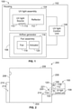
- FIG. 1 illustrates a schematic diagram of a UV light sanitizing system 100, according to an embodiment of the present disclosure.
- the UV light sanitizing system 100 includes a housing 102 that retains a UV light assembly 104, an airflow generator 106, and a UV light control unit 108.
- the UV light assembly 104, the airflow generator 106, and the UV light control unit 108 may be disposed within the housing 102, such as within an internal chamber defined by outer walls.
- one or more of the UV light assembly 104, the airflow generator 106, and the UV light control unit 108 may be mounted on an outer surface of the housing 102.
- the airflow generator 106 and/or the UV light control unit 108 may be remotely located from the housing 102.
- the airflow generator 106 may be secured on and/or proximate (for example, within less than 12.7 cm (five inches)) to a surface of a component that is configured to be sanitized by UV light emitted from the UV light assembly 104.
- the UV light assembly 104 includes a UV light source 110 and a reflector 112.
- the UV light source 110 may be secured within a volume of space defined by the reflector 112.
- the reflector 112 may be a parabolic reflector (such as formed of aluminum, and/or having internal mirror reflecting surfaces), and the UV light source 110 may be within an internal volume of space defined by the parabolic reflector.
- the reflector 112 may be shaped differently than a parabola.
- the UV light source 110 itself may include the reflector 112. In at least one other embodiment, the UV light assembly 104 may not include the reflector 112.
- the UV light source 110 is operatively coupled to the UV light control unit 108.
- the UV light source 110 may include one or more UV light elements 114, such as an arc lamp(s), laser(s), light emitting diode(s) (LEDs), microfilament(s), bulbs, fiber optic elements, and/or the like that are configured to emit UV light onto one or more structures within a confined space during a sanitizing cycle.
- the UV light elements 114 are configured to emit far UV light.
- the UV light elements 114 may be configured to emit other types of UV light, such as UVA light, UVB light, UVC light, vacuum UV light, and/or the like.
- the UV light source 110 may include UV light elements that are configured to emit UV light with different UV bands (for example, at different wavelengths and different frequencies).
- one UV light element may be configured to emit far UV light, while another UV light element may be configured to emit UVC light.
- the UV light control unit 108 is coupled to the UV light assembly 104 through one or more wired or wireless connections, and is configured to control operation of the UV light assembly 104.
- the UV light control unit 108 outputs an activation signal that is received by the UV light assembly 104, in particular the UV light source 110.
- the activation signal activates and controls the UV light source 110 during a sanitizing cycle in which the UV light source 110 emits UV light onto one or more structures within a confined space.
- the UV light control unit 108 may include or otherwise be coupled to a memory that stores data regarding the sanitizing cycle.
- the airflow generator 106 is also operatively coupled to the UV light control unit 108, such as through one or more wired or wireless connections.
- the airflow generator 106 includes a fan assembly 116 including a fan 118 (such as a rotor with blades) operatively coupled to an actuator 120 (such as an electric motor).
- the airflow generator 106 may be or include an electronic spooling fan, a bladeless fan, one or more oscillating vanes, and/or the like.
- the airflow generator 106 is configured to generate airflow in the region where UV light is emitted from the UV light source 110 and/or onto a surface where the emitted UV light is directed.
- the UV light control unit 108 activates the UV light source 110 to emit UV light onto a surface to be sanitized during a sanitizing cycle.
- the UV light control unit also activates the airflow generator 106 to generate airflow in the region of UV light emission (such as between the UV light source 110 and the surface to the sanitized by the emitted UV light).
- the UV light control unit 108 when the UV light control unit 108 initiates the sanitizing cycle, the UV light control unit 108 first activates the airflow generator 106 to generate airflow before the UV light source 110 is activated to emit UV light.
- the airflow generator 106 may be activated for one second before the UV light source 110 is activated, in order for the airflow generator 106 to achieve a full operational speed before UV light is emitted from the UV light source 110.
- the airflow generator 106 may be activated for a period of less than one second before the UV light source 110 is activated.
- the airflow generator 106 is operated during the sanitizing cycle.
- the airflow generator 106 may be operated to generate airflow through and/or within a region of UV light emission for as long as the UV light source 110 emits UV light (such as for two or three seconds).
- the airflow generator 106 may remain active to generate airflow for a predetermined period of time after the UV light source 110 is deactivated, such as for an additional one or two seconds.
- the airflow generator 106 may include the fan assembly 116, which may include the fan 118 operatively coupled to the actuator 120
- the UV light control unit 108 may be operatively coupled to the actuator 120, such as through one or more wired or wireless connections.
- the actuator 120 may be an electronic or electric motor, one or more solenoids, or the like that causes the fan 118 to rotate, such as through a rotor operatively coupled to the actuator 120. Blades coupled to the rotor generate airflow as the rotor of the fan rotates.
- the fan 118 may cause airflow to be directed towards the UV light source 110, across the UV light source 110, and/or across an aperture or other such opening in the housing 102 through which UV light is emitted.
- the fan 118 may operate to blow air onto and/or around the UV light source 110.
- the fan 118 may operate to draw air into, onto and/or around the UV light source 110.
- the fan 118 may cause airflow to be directed towards a surface that is configured to be sanitized by the UV light emitted from the UV light source 110, and across the surface.
- the fan 118 may operate to blow air onto and/or across the surface that is being sanitized by the UV light.
- the fan 118 may operate to draw air into, onto, and/or around the surface that is being sanitized by the UV light.
- the airflow generator 106 is configured to generate airflow in at least a portion of a region of UV light emission between the UV light source 110 and the surface of a component that is being sanitized by the UV light emitted by the UV light source 110.
- the airflow generator 106 generates the airflow along and/or across the region of UV light generation.
- the UV light sanitizing system 100 exploits a chemical process through which UV light converts oxygen (O 2 ) molecules into ozone (O 3 ) molecules.
- UV light photons excite two O 2 molecules from a ground state to an excited state.
- the two excited O 2 molecules typically bump into each other before they decay to a less-excited state.
- the rate of ozone production in a given volume is therefore not linear in relation to the concentration of excited O 2 molecules. Rather, the rate of ozone of production is proportional to the square of the concentration of excited O 2 molecules.
- UV light is concentrated in a small volume within the lavatory (for example, the region between the UV light source 110 and a surface, such as a countertop, that is to be disinfected). Almost all the excited O 2 molecules are produced in the small volume of space.
- the airflow generator 106 disrupts production of ozone by generating airflow in at least a portion of the region of UV light generation, thereby dispersing the excited O 2 molecules. In doing so, the excited O 2 molecules are unlikely (or less likely) to bump into each other before they decay to a less-excited state.
- the airflow generator 106 generates the airflow proximate to (for example, within 15.24 or less cm (6 or less inches)) the UV light source 110 and/or the surface to be disinfected.
- the generated airflow then circulates throughout the enclosed space, carrying the excited O 2 molecules along with it, thereby dispersing the excited O 2 molecules from the region close to the UV light source 110 into an entire enclosed space, such as a lavatory.
- the volume ratio of the region of the UV light source 110 to an entire region of a lavatory is 1:100.
- Excited O 2 molecules with concentration X in the small region are diffused to a concentration of X/100 in the entire lavatory.
- the diffusion reduces the ozone production rate by a factor of 100 2 (that is, a factor of 10,000).
- the time constant for excited O 2 decaying to ground-state O 2 is unchanged, so decay becomes far more likely than ozone production.
- Such dramatic reduction in ozone production reduces the need for costly ozone countermeasures.
- the UV light sanitizing system 100 provides efficient and effective sanitation through emission of UV light onto a surface.
- the UV light sanitizing system 100 saves energy, cycle time, and conditioned air, as compared to an alternative of completely flushing air from the enclosed space. Further, compared to using an ozone filter, the UV light sanitizing system 100 saves energy, cycle time, and maintenance time and effort.
- control unit central processing unit
- CPU central processing unit
- CPU central processing unit
- CPU central processing unit
- CPU central processing unit
- CPU central processing unit
- ASIC application specific integrated circuit
- logic circuits any other circuit or processor including hardware, software, or a combination thereof capable of executing the functions described herein.
- RISC reduced instruction set computers
- ASICs application specific integrated circuits
- the UV light control unit 108 may be or include one or more processors.
- the UV light control unit 108 is configured to execute a set of instructions that are stored in one or more data storage units or elements (such as one or more memories), in order to process data.
- the UV light control unit 108 may include or be coupled to one or more memories.
- the data storage units may also store data or other information as desired or needed.
- the data storage units may be in the form of an information source or a physical memory element within a processing machine.
- the set of instructions may include various commands that instruct the UV light control unit 108 as a processing machine to perform specific operations such as the methods and processes of the various embodiments of the subject matter described herein.
- the set of instructions may be in the form of a software program.
- the software may be in various forms such as system software or application software. Further, the software may be in the form of a collection of separate programs, a program subset within a larger program or a portion of a program.
- the software may also include modular programming in the form of object-oriented programming.
- the processing of input data by the processing machine may be in response to user commands, or in response to results of previous processing, or in response to a request made by another processing machine.
- the diagrams of embodiments herein may illustrate one or more control or processing units, such as the UV light control unit 108.
- the processing or control units may represent circuits, circuitry, or portions thereof that may be implemented as hardware with associated instructions (e.g., software stored on a tangible and non-transitory computer readable storage medium, such as a computer hard drive, ROM, RAM, or the like) that perform the operations described herein.
- the hardware may include state machine circuitry hardwired to perform the functions described herein.
- the hardware may include electronic circuits that include and/or are connected to one or more logic-based devices, such as microprocessors, processors, controllers, or the like.
- the UV light control unit 108 may represent processing circuitry such as one or more of a field programmable gate array (FPGA), application specific integrated circuit (ASIC), microprocessor(s), and/or the like.
- the circuits in various embodiments may be configured to execute one or more algorithms to perform functions described herein.
- the one or more algorithms may include aspects of embodiments disclosed herein, whether or not expressly identified in a flowchart or a method.
- the terms "software” and “firmware” are interchangeable, and include any computer program stored in a data storage unit (for example, one or more memories) for execution by a computer, including RAM memory, ROM memory, EPROM memory, EEPROM memory, and non-volatile RAM (NVRAM) memory.
- a data storage unit for example, one or more memories
- NVRAM non-volatile RAM
- the above data storage unit types are exemplary only, and are thus not limiting as to the types of memory usable for storage of a computer program.
- FIG. 2 illustrates a schematic diagram of the UV light sanitizing system 100 for an enclosed space 200, according to an embodiment of the present disclosure.
- the enclosed space 200 may be defined by a floor 204, a ceiling 206, and walls 208 extending between the floor 204 and the ceiling 206.
- a door 210 may be moveably secured to one of the walls 208.
- the door 210 may include a lock 212 that is configured to securely lock the door 210 in a closed position. When the lock 212 is in a locked position, the door 210 is unable to be opened. When the lock 212 is in an unlocked position, the door 210 may be opened.
- the enclosed space 200 may be a lavatory onboard an aircraft.
- the enclosed space 200 may or may not include the door 210.
- the enclosed space 200 may be within various other vehicles, structures, and/or the like.
- the enclosed space 200 may be a room within a commercial, municipal, or residential building, or a room onboard a train, bus, ship, or the like.
- the enclosed space 200 includes at least one component 214 to be sanitized (for example, disinfected, sterilized, or otherwise cleaned) after use.
- the component 214 may be a toilet, sink, floor, cabinet, wall, and/or the like within a lavatory of an aircraft.
- the UV light sanitizing system 100 may be flush-mounted with one of the walls 208.
- the UV light sanitizing system 100 may be mounted on an outer surface of the wall 208.
- the UV light sanitizing system 100 may be secured to the ceiling 206.
- the UV light sanitizing system 100 may be secured to the floor 204, and/or the component 214.
- the UV light assembly 104 is configured to emit UV light 220 onto a surface of the component 214 during a sanitizing cycle.
- the UV light 220 is emitted in a region of UV light emission 221 between the UV light assembly 104 and the surface of the component 214 during the sanitizing cycle.
- the airflow generator 106 which may include the fan 118 operatively coupled to the actuator 120, generates airflow in at least a portion of the region of UV light emission (such as before, during, and/or after the emission of UV light from the UV light assembly 104), thereby disrupting generation of ozone, as described above.
- FIG. 3 illustrates a simplified view of the UV light sanitizing system 100, according to an embodiment of the present disclosure.
- the housing 102 may include opaque outer walls 150 connected to a light outlet passage 152, such as an aperture or other such opening, a transparent window (such as formed of glass or clear plastic), and/or the like.
- the light source 110 may be secured to the housing 102 through fasteners, brackets, or other such mounting features.
- the light source 110 may be secured to the reflector 112 through at least one retaining member, such as a socket(s), a bracket(s), a fastener(s), a guide track(s), rail(s), a clasp(s), a sleeve(s), and/or the like.
- the airflow generator 106 may include one or more fans 118 secured to the housing 102 proximate to the light outlet passage 152.
- the fan(s) 118 may be oriented to blow and/or draw air across the light outlet passage 152. That is, the fan(s) 118 may be oriented and configured to blow and/or draw air across a portion of the region of UV light emission.
- FIG. 4 illustrates a simplified view of a UV light sanitizing system 100, according to an embodiment of the present disclosure.
- the airflow generator 106 may be mounted to the housing 102 behind the UV light source 110.
- the airflow generator 106 may include one or more fans 118 that are configured to blow and/or draw air into and/or around the UV light source 110, thereby reducing ozone formation and cooling at the UV light source 110 at the same time.
- Figure 5 illustrates a simplified view of a UV light sanitizing system 100, according to an embodiment of the present disclosure.
- the airflow generator 106 may be remotely located from the housing 102.
- the airflow generator 106 may be mounted onto and/or proximate to the component 214, and configured to blow and/or draw air onto and/or across the surface of the component 214 that is configured to be sanitized by the UV light emitted by the UV light source 110.
- FIG. 6 illustrates a simplified view of a UV light sanitizing system 100, according to an embodiment of the present disclosure.
- the airflow generator 106 may be mounted to the housing 102 through one or more brackets 160.
- One or more fans 118 are directed toward the interior of the housing 102 and/or the UV light source 110.
- the airflow generator 106 before, and during, and/or after a sanitizing cycle, the airflow generator 106 generates airflow within at least a portion of a region of UV light emission between the UV light source 110 and the component 214 that is sterilized through the UV light generated by the UV light source 110.
- the airflow generator 106 By generating the airflow within at least a portion of the region of UV light emission, excited oxygen molecules are dispersed throughout the enclosed space 200, thereby reducing the likelihood of ozone molecules forming.
- the enclosed space 200 may also include vents and/or additional fans located therein and/or throughout.
- the vents and/or additional fans are configured to reduce air stagnation at areas within the enclosed space 200.
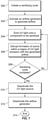
- FIG. 7 illustrates a flow chart of a method of sanitizing a component with UV light, according to an embodiment of the present disclosure.
- the UV light control unit 108 initiates a sanitizing cycle (such as after use of a lavatory onboard an aircraft by an individual).
- the UV light control unit 108 activates the airflow generator 106 to generate airflow.
- the UV light control unit 108 activates the UV light source 110 to emit UV light onto a component to be sanitized. Step 302 occurs prior to 304.
- formation of ozone is disrupted within a region of UV light emission by the generated airflow.
- the UV light control unit 108 determines whether the sanitizing cycle is complete. If the sanitizing cycle is not complete, the method returns to 304. If, however, the sanitizing cycle is complete at 308, the method proceeds to 310, at which the UV light control unit 108 deactivates the UV light source 110. At 312, the UV light control unit 108 then deactivates the airflow generator 106. Step 310 may occur prior to step 312. Optionally, steps 310 and 312 may occur simultaneously. The method ends at 314.
- FIG 8 illustrates a perspective front view of an aircraft 400, according to an embodiment of the present disclosure.
- the aircraft 400 includes a propulsion system 412 that may include two turbofan engines 414, for example.
- the propulsion system 412 may include more engines 414 than shown.
- the engines 414 are carried by wings 416 of the aircraft 400.
- the engines 414 may be carried by a fuselage 418 and/or an empennage 420.
- the empennage 420 may also support horizontal stabilizers 422 and a vertical stabilizer 424.
- the fuselage 418 of the aircraft 400 defines an internal cabin, which may include a cockpit 430, one or more work sections (for example, galleys, personnel carry-on baggage areas, and the like), one or more passenger sections (for example, first class, business class, and coach sections), and an aft section in which an aft rest area assembly may be positioned. Each of the sections may be separated by a cabin transition area, which may include one or more class divider assemblies. Overhead stowage bin assemblies may be positioned throughout the internal cabin.
- the internal cabin includes one or more chambers, such as lavatories, for example.
- One or more UV light sanitizing systems 100 may be located within the internal cabin.
- embodiments of the present disclosure may be used with various other vehicles, such as automobiles, buses, locomotives and train cars, watercraft, and the like. Further, embodiments of the present disclosure may be used with respect to fixed structures, such as commercial and residential buildings.
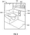
- Figure 9 illustrates a perspective internal view of a lavatory 200, according to the claimed invention.
- the lavatory 200 is an example of the enclosed space 200 shown and described with respect to Figure 2 , for example.
- the lavatory 200 may be onboard an aircraft, as described above.
- the lavatory 200 may be onboard various other vehicles.
- the lavatory 200 may be within a fixed structure, such as a commercial or residential building.
- the lavatory 200 includes a base floor 502 that supports a toilet 500, cabinets 506, and a sink 502.
- UV light sanitizing systems 100 are secured within the lavatory 200 and are configured to be activated during a sanitizing cycle to sanitize (for example, disinfect, sterilize, or otherwise clean) various structures within the lavatory 200, such as the toilet 500, the floor 502, the cabinets 506, and/or the sink 502.
- embodiments of the present disclosure provide UV light sanitizing systems and methods that eliminate, minimize, or otherwise reduce ozone within a confined space.
- the UV light sanitizing systems and methods disrupt ozone generation within a confined space.
- a structure, limitation, or element that is "configured to” perform a task or operation is particularly structurally formed, constructed, or adapted in a manner corresponding to the task or operation.
- an object that is merely capable of being modified to perform the task or operation is not “configured to” perform the task or operation as used herein.
Landscapes
- Health & Medical Sciences (AREA)
- Public Health (AREA)
- Epidemiology (AREA)
- Life Sciences & Earth Sciences (AREA)
- Animal Behavior & Ethology (AREA)
- General Health & Medical Sciences (AREA)
- Veterinary Medicine (AREA)
- Engineering & Computer Science (AREA)
- Hydrology & Water Resources (AREA)
- Water Supply & Treatment (AREA)
- Apparatus For Disinfection Or Sterilisation (AREA)
- Disinfection, Sterilisation Or Deodorisation Of Air (AREA)
Claims (12)
- Waschraumanordnung (200), die einen geschlossenen Raum bildet und ein Ultraviolett-Licht-(UV-Licht)-Desinfektionssystem aufweist, das dazu konfiguriert ist, eine Oberfläche einer Struktur innerhalb der Waschraumanordnung zu desinfizieren, wie einer Toilette (500), eines Bodens (502), von Schränken (506) und/oder eines Waschbeckens (502), wobei das UV-Licht-Desinfektionssystem aufweist:eine UV-Licht-Anordnung (104), die eine UV-Licht-Quelle (110) aufweist, die dazu konfiguriert ist, UV-Licht auf die Oberfläche der Struktur zu emittieren, wobei das UV-Licht aufgrund seiner UV-Licht-Photonen Sauerstoffmoleküle von einem Grundzustand in einen angeregten Zustand anregt; undeinen Luftströmungs-Generator (106), der dazu konfiguriert ist, eine Luftströmung nahe der UV-Licht-Quelle (110) und/oder der zu desinfizierenden Oberfläche und innerhalb einer Region einer UV-Licht-Emission zwischen der UV-Licht-Quelle (110) und der Oberfläche der Struktur zu erzeugen, wobei die erzeugte Luftströmung dann durch den geschlossenen Raum zirkuliert, wobei sie die angeregten Sauerstoffmoleküle mit sich trägt, wodurch die angeregten Sauerstoffmoleküle aus der Region nahe der UV-Licht-Quelle (110) in dem gesamten geschlossenen Raum verteilt werden, der von der Waschraumanordnung gebildet wird, so dass die von dem Luftströmungs-Generator (106) erzeugte Luftströmung die Bildung von Ozon stört, wobei das UV-Licht-Desinfektionssystem ferner eine UV-Licht-Steuereinheit (108) aufweist, die betriebsmäßig mit der UV-Licht-Anordnung (104) und dem Luftströmungs-Generator (106) gekoppelt ist, wobei die UV-Licht-Steuereinheit (108) dazu konfiguriert ist, einen Betrieb der UV-Licht-Anordnung (104) und des Luftströmungs-Generators (106) zu steuern, wobei die UV-Licht-Steuereinheit (108) dazu konfiguriert ist, die UV-Licht-Quelle während eines Desinfektionszyklus zu aktivieren, wobei die UV-Licht-Steuereinheit (108) dazu konfiguriert ist, den Luftströmungs-Generator (106) während des Desinfektionszyklus zu aktivieren, bevor die UV-Licht-Quelle aktiviert wird.
- Waschraumanordnung nach Anspruch 1, wobei das UV-Licht-Desinfektionssystem ferner ein Gehäuse (102) aufweist, wobei die UV-Licht-Anordnung (104) innerhalb des Gehäuses (102) festgelegt ist.
- Waschraumanordnung nach Anspruch 2, wobei der Luftströmungs-Generator (106) an dem Gehäuse (102) festgelegt ist.
- Waschraumanordnung nach einem beliebigen der Ansprüche 1 bis 3, wobei der Luftströmungs-Generator (106) eine Lüfteranordnung aufweist, die wenigstens einen Lüfter (118) beinhaltet, der betriebsmäßig mit wenigstens einem Aktuator (120) gekoppelt ist.
- Waschraumanordnung nach einem beliebigen der Ansprüche 1 bis 4, wobei der Luftströmungs-Generator (106) dazu konfiguriert ist, eine Luftströmung entlang der Region einer UV-Licht-Emission zu erzeugen.
- Waschraumanordnung nach einem beliebigen der Ansprüche 1 bis 5, wobei der Luftströmungs-Generator (106) dazu konfiguriert ist, eine Luftströmung quer über die Region einer UV-Licht-Emission zu erzeugen.
- Ultraviolett-Licht-(UV-Licht)-Desinfektionsverfahren zum Desinfizieren einer Oberfläche einer Struktur innerhalb einer Waschraumanordnung (200), wie einer Toilette (500), einem Boden (502), von Schränken (506) und/oder einem Waschbecken (502), wobei das UV-Licht-Desinfektionsverfahren aufweist:Emittieren von UV-Licht auf die Oberfläche der Struktur mittels einer UV-Licht-Quelle (110) einer UV-Licht-Anordnung (104), wobei das UV-Licht mittels seiner UV-Licht-Photonen, die Sauerstoffmoleküle von einem Grundzustand in einen angeregten Zustand anregen, Sauerstoffmoleküle in Ozon-Moleküle wandelt;Verwenden eines Luftströmungs-Generators (106), um eine Luftströmung in der Nähe der UV-Licht-Quelle (110) und/oder der zu desinfizierenden Oberfläche und innerhalb einer Region von UV-Licht-Emission zwischen der UV-Licht-Quelle (110) und der Oberfläche der Struktur zu erzeugen, wobei die erzeugte Luftströmung dann durch den geschlossenen Raum zirkuliert, wobei sie die angeregten Sauerstoffmoleküle mit sich trägt, wodurch die angeregten Sauerstoffmoleküle aus der Region nahe der UV-Licht-Quelle (110) in dem gesamten geschlossenen Raum verteilt werden, der von der Waschraumanordnung gebildet wird, so dass die von dem Luftströmungs-Generator (106) erzeugte Luftströmung die Bildung von Ozon stört;wobei eine UV-Licht-Steuereinheit (110) betriebsmäßig mit der UV-Licht-Anordnung (104) und dem Luftströmungs-Generator (106) gekoppelt ist;Steuern eines Betriebs der UV-Licht-Anordnung (104) und des Luftströmungs-Generators (106) mittels der UV-Licht-Steuereinheit (108);Aktivieren der UV-Licht-Quelle mittels der UV-Licht-Steuereinheit (108) während eines Desinfektionszyklus; undAktivieren des Luftströmungs-Generators (106) mittels der UV-Licht-Steuereinheit (108) während des Desinfektionszyklus, bevor die UV-Licht-Quelle aktiviert wird.
- UV-Licht-Desinfektionsverfahren nach Anspruch 7, ferner mit dem Schritt des Festlegens der UV-Licht-Anordnung (104) innerhalb eines Gehäuses (102).
- UV-Licht-Desinfektionsverfahren nach Anspruch 7 oder 8, ferner mit dem Schritt des Festlegens des Luftströmungs-Generators (106) an einem Gehäuse (102).
- UV-Licht-Desinfektionsverfahren nach einem beliebigen der Ansprüche 7 bis 9, ferner mit dem Schritt, den Luftströmungs-Generator (106) entfernt von einem Gehäuse (102) anzuordnen, wobei das entfernte Anordnen beinhaltet, den Luftströmungs-Generator (106) innerhalb von weniger als 12,7 cm (fünf Zoll) bis hin zu einem Abschnitt der Komponente festzulegen.
- UV-Licht-Desinfektionsverfahren nach einem beliebigen der Ansprüche 7 bis 10, wobei das Verwenden des Luftströmungs-Generators beinhaltet, die Luftströmung entlang der Region von UV-Licht-Emission zu erzeugen, und/oder wobei das Verwenden des Luftströmungs-Generators beinhaltet, eine Luftströmung quer über die Region der UV-Licht-Emission zu erzeugen.
- Fahrzeug mit:einer inneren Kabine;einer Waschraumanordnung nach Anspruch 1, wobei der Luftströmungs-Generator dazu konfiguriert ist, eine Luftströmung entlang und/oder quer zu der Region der UV-Licht-Emission zu erzeugen; und wobei das UV-Licht-Desinfektionssystem ferner aufweist:
ein Gehäuse, wobei die UV-Licht-Anordnung innerhalb des Gehäuses festgelegt ist.
Applications Claiming Priority (1)
| Application Number | Priority Date | Filing Date | Title |
|---|---|---|---|
| US15/690,338 US20190060496A1 (en) | 2017-08-30 | 2017-08-30 | Ozone-disrupting ultraviolet light sanitizing systems and methods |
Publications (2)
| Publication Number | Publication Date |
|---|---|
| EP3449948A1 EP3449948A1 (de) | 2019-03-06 |
| EP3449948B1 true EP3449948B1 (de) | 2022-02-02 |
Family
ID=63047160
Family Applications (1)
| Application Number | Title | Priority Date | Filing Date |
|---|---|---|---|
| EP18185392.0A Active EP3449948B1 (de) | 2017-08-30 | 2018-07-25 | Ozonzerstörende ultraviolettlichtreinigungssysteme und verfahren |
Country Status (4)
| Country | Link |
|---|---|
| US (1) | US20190060496A1 (de) |
| EP (1) | EP3449948B1 (de) |
| JP (1) | JP7101555B2 (de) |
| CN (1) | CN109420185B (de) |
Families Citing this family (15)
| Publication number | Priority date | Publication date | Assignee | Title |
|---|---|---|---|---|
| US11857705B2 (en) | 2018-01-15 | 2024-01-02 | Aerapy Llc | Method of treating a space |
| US11071799B2 (en) | 2018-02-20 | 2021-07-27 | Freestyle Partners, LLC | Portable and disposable UV device |
| US11020501B1 (en) | 2018-02-20 | 2021-06-01 | Freestyle Partners, LLC | Handheld ultraviolet irradiation device having distance measurement system |
| EP4151241B1 (de) | 2018-02-20 | 2026-01-21 | Freestyle Partners, LLC | Tragbare fern-uvc-vorrichtung |
| WO2020037223A1 (en) * | 2018-08-17 | 2020-02-20 | Mag Aerospace Industries, Llc | Water system floor interface with ultraviolet light treatment |
| CN115515651A (zh) * | 2020-04-01 | 2022-12-23 | 自由风格合伙有限公司 | 安全辐照病原体的系统和方法 |
| US20210315749A1 (en) * | 2020-04-09 | 2021-10-14 | PetAirapy, LLC | Method and apparatus for treating an inside volume of a mobile vehicle |
| US11007292B1 (en) | 2020-05-01 | 2021-05-18 | Uv Innovators, Llc | Automatic power compensation in ultraviolet (UV) light emission device, and related methods of use, particularly suited for decontamination |
| US20210346540A1 (en) * | 2020-05-08 | 2021-11-11 | The Boeing Company | Portable sanitizing system having a backpack assembly coupled to a wand assembly |
| US11883545B2 (en) * | 2020-05-08 | 2024-01-30 | The Boeing Company | Portable sanitizing systems and methods |
| FR3110428B1 (fr) * | 2020-05-19 | 2024-09-06 | Eric Breuil | Dispositif de desinfection d’un interieur de vehicule |
| DE102020004883A1 (de) * | 2020-08-11 | 2022-02-17 | Daimler Ag | Desinfektionssystem |
| US20220204184A1 (en) * | 2020-12-28 | 2022-06-30 | Goodrich Corporation | Aircraft disinfection system for stowable items |
| US20230061757A1 (en) * | 2021-08-31 | 2023-03-02 | Safran Cabin Inc. | Airborne pathogen sanitization system |
| US20230145866A1 (en) * | 2021-11-11 | 2023-05-11 | The Boeing Company | Systems and methods for disinfecting hands |
Citations (4)
| Publication number | Priority date | Publication date | Assignee | Title |
|---|---|---|---|---|
| JPH04300556A (ja) * | 1991-03-28 | 1992-10-23 | Aisin Seiki Co Ltd | 脱臭装置 |
| JP2000315419A (ja) * | 1999-04-28 | 2000-11-14 | Hamamatsu Photonics Kk | ポータブル型光源装置 |
| CN103349424A (zh) * | 2013-07-08 | 2013-10-16 | 四川大学 | 一种自控式牙刷消毒速干放置器 |
| US9144618B2 (en) * | 2013-02-27 | 2015-09-29 | Arthur Kreitenberg | Sanitizing surfaces associated with seating |
Family Cites Families (16)
| Publication number | Priority date | Publication date | Assignee | Title |
|---|---|---|---|---|
| US3949258A (en) * | 1974-12-05 | 1976-04-06 | Baxter Laboratories, Inc. | Method and means for suppressing ozone generated by arc lamps |
| JP2002263596A (ja) | 2001-03-08 | 2002-09-17 | Hoya-Schott Corp | 紫外光照射装置 |
| WO2007035907A2 (en) | 2005-09-21 | 2007-03-29 | Germgard Lighting Corporation | Germicidal lamp |
| EA201290641A1 (ru) * | 2010-01-13 | 2012-12-28 | Металл + Пластик Гмбх | Система обеззараживания, а также способ |
| US9706794B2 (en) | 2010-05-20 | 2017-07-18 | Automatic Bar Controls, Inc. | Ultraviolet disinfecting device for food and beverage dispensers |
| JP5738168B2 (ja) | 2011-12-22 | 2015-06-17 | 三菱重工食品包装機械株式会社 | 電子線殺菌装置 |
| TWI500891B (zh) * | 2012-06-08 | 2015-09-21 | Ind Tech Res Inst | 臭氧消毒乾燥裝置與其方法 |
| PL2908867T3 (pl) * | 2012-10-19 | 2017-06-30 | Jimco A/S | Sposób dezynfekcji powierzchni i/lub sterylizacji powietrza oraz urządzenie do stosowania tego sposobu |
| US9757486B2 (en) * | 2014-11-06 | 2017-09-12 | Sensor Electronic Technology, Inc. | Ultraviolet-based bathroom surface sanitization |
| US9623133B2 (en) | 2015-01-30 | 2017-04-18 | The Boeing Company | Lavatory disinfection system |
| CN104873994B (zh) | 2015-06-11 | 2018-09-04 | 四川大学华西第二医院 | 一种中低度危险性医疗器材的消毒加温装置及其使用方法 |
| JP6070794B1 (ja) | 2015-08-26 | 2017-02-01 | ウシオ電機株式会社 | オゾン発生器 |
| US11648326B2 (en) | 2016-02-04 | 2023-05-16 | Xenex Disinfection Services Inc. | Cabinets for disinfecting objects |
| CN205561005U (zh) * | 2016-04-11 | 2016-09-07 | 陈国钧 | 一种卫生间净化装置 |
| CN105756256B (zh) * | 2016-05-09 | 2018-08-24 | 浙江风尚建材股份有限公司 | 一种具有消毒功能的集成吊顶 |
| CN106981134A (zh) * | 2017-05-09 | 2017-07-25 | 贾海亮 | 一种具有净化功能的公交自动售货机 |
-
2017
- 2017-08-30 US US15/690,338 patent/US20190060496A1/en not_active Abandoned
-
2018
- 2018-07-18 JP JP2018134861A patent/JP7101555B2/ja active Active
- 2018-07-25 EP EP18185392.0A patent/EP3449948B1/de active Active
- 2018-08-30 CN CN201811001819.4A patent/CN109420185B/zh active Active
Patent Citations (4)
| Publication number | Priority date | Publication date | Assignee | Title |
|---|---|---|---|---|
| JPH04300556A (ja) * | 1991-03-28 | 1992-10-23 | Aisin Seiki Co Ltd | 脱臭装置 |
| JP2000315419A (ja) * | 1999-04-28 | 2000-11-14 | Hamamatsu Photonics Kk | ポータブル型光源装置 |
| US9144618B2 (en) * | 2013-02-27 | 2015-09-29 | Arthur Kreitenberg | Sanitizing surfaces associated with seating |
| CN103349424A (zh) * | 2013-07-08 | 2013-10-16 | 四川大学 | 一种自控式牙刷消毒速干放置器 |
Also Published As
| Publication number | Publication date |
|---|---|
| CN109420185A (zh) | 2019-03-05 |
| JP7101555B2 (ja) | 2022-07-15 |
| US20190060496A1 (en) | 2019-02-28 |
| JP2019042487A (ja) | 2019-03-22 |
| CN109420185B (zh) | 2022-05-24 |
| EP3449948A1 (de) | 2019-03-06 |
Similar Documents
| Publication | Publication Date | Title |
|---|---|---|
| EP3449948B1 (de) | Ozonzerstörende ultraviolettlichtreinigungssysteme und verfahren | |
| EP3287146B1 (de) | Desinfektionssysteme und -verfahren mit ultraviolettem licht mit mehreren wellenlängen | |
| EP3929084B1 (de) | Desinfektionssystem | |
| CN107867401B (zh) | 手干燥系统和方法 | |
| EP3351272B1 (de) | Frahzeug mit toilettenkabine die eine lichtkonvertierende beleuchtungsanordnung umfasst | |
| US12233178B2 (en) | Systems and methods of verifying effective motion of a wand assembly of an ultraviolet (UV) light sanitizing system | |
| JP6979809B2 (ja) | オゾン換気システム及び方法 | |
| JP2022064872A (ja) | 紫外線殺菌システムおよび方法 | |
| JP7744763B2 (ja) | 殺菌システム | |
| EP3922273B1 (de) | Systeme und verfahren zur desinfektion mit sichtbarem lich | |
| US11382993B2 (en) | Portable sanitizing systems and methods with range guidance | |
| CN114617992A (zh) | 具有分布式电源的紫外光消毒系统和方法 | |
| KR102374361B1 (ko) | 소독설비가 구비된 엘리베이터 | |
| US20220024606A1 (en) | Sanitizing galley cart for an internal cabin of a vehicle | |
| CN113827747A (zh) | 紫外光屏蔽系统 | |
| JP2022008228A (ja) | 電力管理システム | |
| EP4019412B1 (de) | Flugzeugdesinfizierungssystem für verstaubare artikel | |
| CN116472190A (zh) | 用于交通工具舱室的消毒系统 |
Legal Events
| Date | Code | Title | Description |
|---|---|---|---|
| PUAI | Public reference made under article 153(3) epc to a published international application that has entered the european phase |
Free format text: ORIGINAL CODE: 0009012 |
|
| STAA | Information on the status of an ep patent application or granted ep patent |
Free format text: STATUS: REQUEST FOR EXAMINATION WAS MADE |
|
| 17P | Request for examination filed |
Effective date: 20180725 |
|
| AK | Designated contracting states |
Kind code of ref document: A1 Designated state(s): AL AT BE BG CH CY CZ DE DK EE ES FI FR GB GR HR HU IE IS IT LI LT LU LV MC MK MT NL NO PL PT RO RS SE SI SK SM TR |
|
| AX | Request for extension of the european patent |
Extension state: BA ME |
|
| STAA | Information on the status of an ep patent application or granted ep patent |
Free format text: STATUS: EXAMINATION IS IN PROGRESS |
|
| 17Q | First examination report despatched |
Effective date: 20191216 |
|
| GRAP | Despatch of communication of intention to grant a patent |
Free format text: ORIGINAL CODE: EPIDOSNIGR1 |
|
| STAA | Information on the status of an ep patent application or granted ep patent |
Free format text: STATUS: GRANT OF PATENT IS INTENDED |
|
| INTG | Intention to grant announced |
Effective date: 20210416 |
|
| GRAJ | Information related to disapproval of communication of intention to grant by the applicant or resumption of examination proceedings by the epo deleted |
Free format text: ORIGINAL CODE: EPIDOSDIGR1 |
|
| STAA | Information on the status of an ep patent application or granted ep patent |
Free format text: STATUS: EXAMINATION IS IN PROGRESS |
|
| GRAP | Despatch of communication of intention to grant a patent |
Free format text: ORIGINAL CODE: EPIDOSNIGR1 |
|
| STAA | Information on the status of an ep patent application or granted ep patent |
Free format text: STATUS: GRANT OF PATENT IS INTENDED |
|
| INTC | Intention to grant announced (deleted) | ||
| INTG | Intention to grant announced |
Effective date: 20210816 |
|
| GRAS | Grant fee paid |
Free format text: ORIGINAL CODE: EPIDOSNIGR3 |
|
| GRAA | (expected) grant |
Free format text: ORIGINAL CODE: 0009210 |
|
| STAA | Information on the status of an ep patent application or granted ep patent |
Free format text: STATUS: THE PATENT HAS BEEN GRANTED |
|
| REG | Reference to a national code |
Ref country code: DE Ref legal event code: R082 Ref document number: 602018030340 Country of ref document: DE Representative=s name: WITTE, WELLER & PARTNER PATENTANWAELTE MBB, DE |
|
| AK | Designated contracting states |
Kind code of ref document: B1 Designated state(s): AL AT BE BG CH CY CZ DE DK EE ES FI FR GB GR HR HU IE IS IT LI LT LU LV MC MK MT NL NO PL PT RO RS SE SI SK SM TR |
|
| REG | Reference to a national code |
Ref country code: GB Ref legal event code: FG4D |
|
| REG | Reference to a national code |
Ref country code: CH Ref legal event code: EP Ref country code: AT Ref legal event code: REF Ref document number: 1466419 Country of ref document: AT Kind code of ref document: T Effective date: 20220215 |
|
| REG | Reference to a national code |
Ref country code: DE Ref legal event code: R096 Ref document number: 602018030340 Country of ref document: DE |
|
| REG | Reference to a national code |
Ref country code: IE Ref legal event code: FG4D |
|
| REG | Reference to a national code |
Ref country code: LT Ref legal event code: MG9D |
|
| REG | Reference to a national code |
Ref country code: NL Ref legal event code: MP Effective date: 20220202 |
|
| REG | Reference to a national code |
Ref country code: AT Ref legal event code: MK05 Ref document number: 1466419 Country of ref document: AT Kind code of ref document: T Effective date: 20220202 |
|
| PG25 | Lapsed in a contracting state [announced via postgrant information from national office to epo] |
Ref country code: SE Free format text: LAPSE BECAUSE OF FAILURE TO SUBMIT A TRANSLATION OF THE DESCRIPTION OR TO PAY THE FEE WITHIN THE PRESCRIBED TIME-LIMIT Effective date: 20220202 Ref country code: RS Free format text: LAPSE BECAUSE OF FAILURE TO SUBMIT A TRANSLATION OF THE DESCRIPTION OR TO PAY THE FEE WITHIN THE PRESCRIBED TIME-LIMIT Effective date: 20220202 Ref country code: PT Free format text: LAPSE BECAUSE OF FAILURE TO SUBMIT A TRANSLATION OF THE DESCRIPTION OR TO PAY THE FEE WITHIN THE PRESCRIBED TIME-LIMIT Effective date: 20220602 Ref country code: NO Free format text: LAPSE BECAUSE OF FAILURE TO SUBMIT A TRANSLATION OF THE DESCRIPTION OR TO PAY THE FEE WITHIN THE PRESCRIBED TIME-LIMIT Effective date: 20220502 Ref country code: NL Free format text: LAPSE BECAUSE OF FAILURE TO SUBMIT A TRANSLATION OF THE DESCRIPTION OR TO PAY THE FEE WITHIN THE PRESCRIBED TIME-LIMIT Effective date: 20220202 Ref country code: LT Free format text: LAPSE BECAUSE OF FAILURE TO SUBMIT A TRANSLATION OF THE DESCRIPTION OR TO PAY THE FEE WITHIN THE PRESCRIBED TIME-LIMIT Effective date: 20220202 Ref country code: HR Free format text: LAPSE BECAUSE OF FAILURE TO SUBMIT A TRANSLATION OF THE DESCRIPTION OR TO PAY THE FEE WITHIN THE PRESCRIBED TIME-LIMIT Effective date: 20220202 Ref country code: ES Free format text: LAPSE BECAUSE OF FAILURE TO SUBMIT A TRANSLATION OF THE DESCRIPTION OR TO PAY THE FEE WITHIN THE PRESCRIBED TIME-LIMIT Effective date: 20220202 Ref country code: BG Free format text: LAPSE BECAUSE OF FAILURE TO SUBMIT A TRANSLATION OF THE DESCRIPTION OR TO PAY THE FEE WITHIN THE PRESCRIBED TIME-LIMIT Effective date: 20220502 |
|
| PG25 | Lapsed in a contracting state [announced via postgrant information from national office to epo] |
Ref country code: PL Free format text: LAPSE BECAUSE OF FAILURE TO SUBMIT A TRANSLATION OF THE DESCRIPTION OR TO PAY THE FEE WITHIN THE PRESCRIBED TIME-LIMIT Effective date: 20220202 Ref country code: LV Free format text: LAPSE BECAUSE OF FAILURE TO SUBMIT A TRANSLATION OF THE DESCRIPTION OR TO PAY THE FEE WITHIN THE PRESCRIBED TIME-LIMIT Effective date: 20220202 Ref country code: GR Free format text: LAPSE BECAUSE OF FAILURE TO SUBMIT A TRANSLATION OF THE DESCRIPTION OR TO PAY THE FEE WITHIN THE PRESCRIBED TIME-LIMIT Effective date: 20220503 Ref country code: FI Free format text: LAPSE BECAUSE OF FAILURE TO SUBMIT A TRANSLATION OF THE DESCRIPTION OR TO PAY THE FEE WITHIN THE PRESCRIBED TIME-LIMIT Effective date: 20220202 Ref country code: AT Free format text: LAPSE BECAUSE OF FAILURE TO SUBMIT A TRANSLATION OF THE DESCRIPTION OR TO PAY THE FEE WITHIN THE PRESCRIBED TIME-LIMIT Effective date: 20220202 |
|
| PG25 | Lapsed in a contracting state [announced via postgrant information from national office to epo] |
Ref country code: IS Free format text: LAPSE BECAUSE OF FAILURE TO SUBMIT A TRANSLATION OF THE DESCRIPTION OR TO PAY THE FEE WITHIN THE PRESCRIBED TIME-LIMIT Effective date: 20220602 |
|
| PG25 | Lapsed in a contracting state [announced via postgrant information from national office to epo] |
Ref country code: SM Free format text: LAPSE BECAUSE OF FAILURE TO SUBMIT A TRANSLATION OF THE DESCRIPTION OR TO PAY THE FEE WITHIN THE PRESCRIBED TIME-LIMIT Effective date: 20220202 Ref country code: SK Free format text: LAPSE BECAUSE OF FAILURE TO SUBMIT A TRANSLATION OF THE DESCRIPTION OR TO PAY THE FEE WITHIN THE PRESCRIBED TIME-LIMIT Effective date: 20220202 Ref country code: RO Free format text: LAPSE BECAUSE OF FAILURE TO SUBMIT A TRANSLATION OF THE DESCRIPTION OR TO PAY THE FEE WITHIN THE PRESCRIBED TIME-LIMIT Effective date: 20220202 Ref country code: EE Free format text: LAPSE BECAUSE OF FAILURE TO SUBMIT A TRANSLATION OF THE DESCRIPTION OR TO PAY THE FEE WITHIN THE PRESCRIBED TIME-LIMIT Effective date: 20220202 Ref country code: DK Free format text: LAPSE BECAUSE OF FAILURE TO SUBMIT A TRANSLATION OF THE DESCRIPTION OR TO PAY THE FEE WITHIN THE PRESCRIBED TIME-LIMIT Effective date: 20220202 Ref country code: CZ Free format text: LAPSE BECAUSE OF FAILURE TO SUBMIT A TRANSLATION OF THE DESCRIPTION OR TO PAY THE FEE WITHIN THE PRESCRIBED TIME-LIMIT Effective date: 20220202 |
|
| REG | Reference to a national code |
Ref country code: DE Ref legal event code: R097 Ref document number: 602018030340 Country of ref document: DE |
|
| PG25 | Lapsed in a contracting state [announced via postgrant information from national office to epo] |
Ref country code: AL Free format text: LAPSE BECAUSE OF FAILURE TO SUBMIT A TRANSLATION OF THE DESCRIPTION OR TO PAY THE FEE WITHIN THE PRESCRIBED TIME-LIMIT Effective date: 20220202 |
|
| PLBE | No opposition filed within time limit |
Free format text: ORIGINAL CODE: 0009261 |
|
| STAA | Information on the status of an ep patent application or granted ep patent |
Free format text: STATUS: NO OPPOSITION FILED WITHIN TIME LIMIT |
|
| 26N | No opposition filed |
Effective date: 20221103 |
|
| PG25 | Lapsed in a contracting state [announced via postgrant information from national office to epo] |
Ref country code: SI Free format text: LAPSE BECAUSE OF FAILURE TO SUBMIT A TRANSLATION OF THE DESCRIPTION OR TO PAY THE FEE WITHIN THE PRESCRIBED TIME-LIMIT Effective date: 20220202 Ref country code: MC Free format text: LAPSE BECAUSE OF FAILURE TO SUBMIT A TRANSLATION OF THE DESCRIPTION OR TO PAY THE FEE WITHIN THE PRESCRIBED TIME-LIMIT Effective date: 20220202 |
|
| REG | Reference to a national code |
Ref country code: CH Ref legal event code: PL |
|
| REG | Reference to a national code |
Ref country code: BE Ref legal event code: MM Effective date: 20220731 |
|
| PG25 | Lapsed in a contracting state [announced via postgrant information from national office to epo] |
Ref country code: LU Free format text: LAPSE BECAUSE OF NON-PAYMENT OF DUE FEES Effective date: 20220725 Ref country code: LI Free format text: LAPSE BECAUSE OF NON-PAYMENT OF DUE FEES Effective date: 20220731 Ref country code: CH Free format text: LAPSE BECAUSE OF NON-PAYMENT OF DUE FEES Effective date: 20220731 |
|
| PG25 | Lapsed in a contracting state [announced via postgrant information from national office to epo] |
Ref country code: BE Free format text: LAPSE BECAUSE OF NON-PAYMENT OF DUE FEES Effective date: 20220731 |
|
| P01 | Opt-out of the competence of the unified patent court (upc) registered |
Effective date: 20230516 |
|
| PG25 | Lapsed in a contracting state [announced via postgrant information from national office to epo] |
Ref country code: IT Free format text: LAPSE BECAUSE OF FAILURE TO SUBMIT A TRANSLATION OF THE DESCRIPTION OR TO PAY THE FEE WITHIN THE PRESCRIBED TIME-LIMIT Effective date: 20220202 Ref country code: IE Free format text: LAPSE BECAUSE OF NON-PAYMENT OF DUE FEES Effective date: 20220725 |
|
| PG25 | Lapsed in a contracting state [announced via postgrant information from national office to epo] |
Ref country code: HU Free format text: LAPSE BECAUSE OF FAILURE TO SUBMIT A TRANSLATION OF THE DESCRIPTION OR TO PAY THE FEE WITHIN THE PRESCRIBED TIME-LIMIT; INVALID AB INITIO Effective date: 20180725 |
|
| PG25 | Lapsed in a contracting state [announced via postgrant information from national office to epo] |
Ref country code: MK Free format text: LAPSE BECAUSE OF FAILURE TO SUBMIT A TRANSLATION OF THE DESCRIPTION OR TO PAY THE FEE WITHIN THE PRESCRIBED TIME-LIMIT Effective date: 20220202 Ref country code: CY Free format text: LAPSE BECAUSE OF FAILURE TO SUBMIT A TRANSLATION OF THE DESCRIPTION OR TO PAY THE FEE WITHIN THE PRESCRIBED TIME-LIMIT Effective date: 20220202 |
|
| PG25 | Lapsed in a contracting state [announced via postgrant information from national office to epo] |
Ref country code: MT Free format text: LAPSE BECAUSE OF FAILURE TO SUBMIT A TRANSLATION OF THE DESCRIPTION OR TO PAY THE FEE WITHIN THE PRESCRIBED TIME-LIMIT Effective date: 20220202 |
|
| PGFP | Annual fee paid to national office [announced via postgrant information from national office to epo] |
Ref country code: DE Payment date: 20250729 Year of fee payment: 8 |
|
| PGFP | Annual fee paid to national office [announced via postgrant information from national office to epo] |
Ref country code: GB Payment date: 20250728 Year of fee payment: 8 |
|
| PGFP | Annual fee paid to national office [announced via postgrant information from national office to epo] |
Ref country code: FR Payment date: 20250725 Year of fee payment: 8 |
|
| PG25 | Lapsed in a contracting state [announced via postgrant information from national office to epo] |
Ref country code: TR Free format text: LAPSE BECAUSE OF FAILURE TO SUBMIT A TRANSLATION OF THE DESCRIPTION OR TO PAY THE FEE WITHIN THE PRESCRIBED TIME-LIMIT Effective date: 20220202 |