EP3929084B1 - Desinfektionssystem - Google Patents
Desinfektionssystem Download PDFInfo
- Publication number
- EP3929084B1 EP3929084B1 EP21181076.7A EP21181076A EP3929084B1 EP 3929084 B1 EP3929084 B1 EP 3929084B1 EP 21181076 A EP21181076 A EP 21181076A EP 3929084 B1 EP3929084 B1 EP 3929084B1
- Authority
- EP
- European Patent Office
- Prior art keywords
- lamps
- vehicle
- light
- control unit
- passengers
- Prior art date
- Legal status (The legal status is an assumption and is not a legal conclusion. Google has not performed a legal analysis and makes no representation as to the accuracy of the status listed.)
- Active
Links
Images


Classifications
-
- B—PERFORMING OPERATIONS; TRANSPORTING
- B64—AIRCRAFT; AVIATION; COSMONAUTICS
- B64D—EQUIPMENT FOR FITTING IN OR TO AIRCRAFT; FLIGHT SUITS; PARACHUTES; ARRANGEMENT OR MOUNTING OF POWER PLANTS OR PROPULSION TRANSMISSIONS IN AIRCRAFT
- B64D11/00—Passenger or crew accommodation; Flight-deck installations not otherwise provided for
-
- A—HUMAN NECESSITIES
- A61—MEDICAL OR VETERINARY SCIENCE; HYGIENE
- A61L—METHODS OR APPARATUS FOR STERILISING MATERIALS OR OBJECTS IN GENERAL; DISINFECTION, STERILISATION OR DEODORISATION OF AIR; CHEMICAL ASPECTS OF BANDAGES, DRESSINGS, ABSORBENT PADS OR SURGICAL ARTICLES; MATERIALS FOR BANDAGES, DRESSINGS, ABSORBENT PADS OR SURGICAL ARTICLES
- A61L2/00—Disinfection or sterilisation of materials or objects, in general; Accessories therefor
- A61L2/24—Apparatus using programmed or automatic operation
-
- A—HUMAN NECESSITIES
- A61—MEDICAL OR VETERINARY SCIENCE; HYGIENE
- A61L—METHODS OR APPARATUS FOR STERILISING MATERIALS OR OBJECTS IN GENERAL; DISINFECTION, STERILISATION OR DEODORISATION OF AIR; CHEMICAL ASPECTS OF BANDAGES, DRESSINGS, ABSORBENT PADS OR SURGICAL ARTICLES; MATERIALS FOR BANDAGES, DRESSINGS, ABSORBENT PADS OR SURGICAL ARTICLES
- A61L2/00—Disinfection or sterilisation of materials or objects, in general; Accessories therefor
- A61L2/26—Accessories
-
- A—HUMAN NECESSITIES
- A61—MEDICAL OR VETERINARY SCIENCE; HYGIENE
- A61L—METHODS OR APPARATUS FOR STERILISING MATERIALS OR OBJECTS IN GENERAL; DISINFECTION, STERILISATION OR DEODORISATION OF AIR; CHEMICAL ASPECTS OF BANDAGES, DRESSINGS, ABSORBENT PADS OR SURGICAL ARTICLES; MATERIALS FOR BANDAGES, DRESSINGS, ABSORBENT PADS OR SURGICAL ARTICLES
- A61L9/00—Disinfection, sterilisation or deodorisation of air
- A61L9/16—Disinfection, sterilisation or deodorisation of air using physical phenomena
- A61L9/18—Radiation
- A61L9/20—Ultraviolet radiation
-
- B—PERFORMING OPERATIONS; TRANSPORTING
- B61—RAILWAYS
- B61D—BODY DETAILS OR KINDS OF RAILWAY VEHICLES
- B61D29/00—Lighting
-
- B—PERFORMING OPERATIONS; TRANSPORTING
- B64—AIRCRAFT; AVIATION; COSMONAUTICS
- B64D—EQUIPMENT FOR FITTING IN OR TO AIRCRAFT; FLIGHT SUITS; PARACHUTES; ARRANGEMENT OR MOUNTING OF POWER PLANTS OR PROPULSION TRANSMISSIONS IN AIRCRAFT
- B64D13/00—Arrangements or adaptations of air-treatment apparatus for aircraft crew or passengers, or freight space
-
- A—HUMAN NECESSITIES
- A61—MEDICAL OR VETERINARY SCIENCE; HYGIENE
- A61L—METHODS OR APPARATUS FOR STERILISING MATERIALS OR OBJECTS IN GENERAL; DISINFECTION, STERILISATION OR DEODORISATION OF AIR; CHEMICAL ASPECTS OF BANDAGES, DRESSINGS, ABSORBENT PADS OR SURGICAL ARTICLES; MATERIALS FOR BANDAGES, DRESSINGS, ABSORBENT PADS OR SURGICAL ARTICLES
- A61L2/00—Disinfection or sterilisation of materials or objects, in general; Accessories therefor
- A61L2/02—Disinfection or sterilisation of materials or objects, in general; Accessories therefor using physical processes
- A61L2/08—Radiation
- A61L2/10—Ultraviolet [UV] radiation
-
- A—HUMAN NECESSITIES
- A61—MEDICAL OR VETERINARY SCIENCE; HYGIENE
- A61L—METHODS OR APPARATUS FOR STERILISING MATERIALS OR OBJECTS IN GENERAL; DISINFECTION, STERILISATION OR DEODORISATION OF AIR; CHEMICAL ASPECTS OF BANDAGES, DRESSINGS, ABSORBENT PADS OR SURGICAL ARTICLES; MATERIALS FOR BANDAGES, DRESSINGS, ABSORBENT PADS OR SURGICAL ARTICLES
- A61L2103/00—Materials or objects being the target of disinfection or sterilisation
- A61L2103/75—Room floors or walls
-
- A—HUMAN NECESSITIES
- A61—MEDICAL OR VETERINARY SCIENCE; HYGIENE
- A61L—METHODS OR APPARATUS FOR STERILISING MATERIALS OR OBJECTS IN GENERAL; DISINFECTION, STERILISATION OR DEODORISATION OF AIR; CHEMICAL ASPECTS OF BANDAGES, DRESSINGS, ABSORBENT PADS OR SURGICAL ARTICLES; MATERIALS FOR BANDAGES, DRESSINGS, ABSORBENT PADS OR SURGICAL ARTICLES
- A61L2202/00—Aspects relating to methods or apparatus for disinfecting or sterilising materials or objects
- A61L2202/10—Apparatus features
- A61L2202/11—Apparatus for generating biocidal substances, e.g. vaporisers, UV lamps
-
- A—HUMAN NECESSITIES
- A61—MEDICAL OR VETERINARY SCIENCE; HYGIENE
- A61L—METHODS OR APPARATUS FOR STERILISING MATERIALS OR OBJECTS IN GENERAL; DISINFECTION, STERILISATION OR DEODORISATION OF AIR; CHEMICAL ASPECTS OF BANDAGES, DRESSINGS, ABSORBENT PADS OR SURGICAL ARTICLES; MATERIALS FOR BANDAGES, DRESSINGS, ABSORBENT PADS OR SURGICAL ARTICLES
- A61L2202/00—Aspects relating to methods or apparatus for disinfecting or sterilising materials or objects
- A61L2202/10—Apparatus features
- A61L2202/14—Means for controlling sterilisation processes, data processing, presentation and storage means, e.g. sensors, controllers, programs
-
- A—HUMAN NECESSITIES
- A61—MEDICAL OR VETERINARY SCIENCE; HYGIENE
- A61L—METHODS OR APPARATUS FOR STERILISING MATERIALS OR OBJECTS IN GENERAL; DISINFECTION, STERILISATION OR DEODORISATION OF AIR; CHEMICAL ASPECTS OF BANDAGES, DRESSINGS, ABSORBENT PADS OR SURGICAL ARTICLES; MATERIALS FOR BANDAGES, DRESSINGS, ABSORBENT PADS OR SURGICAL ARTICLES
- A61L2209/00—Aspects relating to disinfection, sterilisation or deodorisation of air
- A61L2209/10—Apparatus features
- A61L2209/11—Apparatus for controlling air treatment
- A61L2209/111—Sensor means, e.g. motion, brightness, scent, contaminant sensors
-
- B—PERFORMING OPERATIONS; TRANSPORTING
- B64—AIRCRAFT; AVIATION; COSMONAUTICS
- B64D—EQUIPMENT FOR FITTING IN OR TO AIRCRAFT; FLIGHT SUITS; PARACHUTES; ARRANGEMENT OR MOUNTING OF POWER PLANTS OR PROPULSION TRANSMISSIONS IN AIRCRAFT
- B64D11/00—Passenger or crew accommodation; Flight-deck installations not otherwise provided for
- B64D2011/0038—Illumination systems for cabins as a whole
-
- B—PERFORMING OPERATIONS; TRANSPORTING
- B64—AIRCRAFT; AVIATION; COSMONAUTICS
- B64D—EQUIPMENT FOR FITTING IN OR TO AIRCRAFT; FLIGHT SUITS; PARACHUTES; ARRANGEMENT OR MOUNTING OF POWER PLANTS OR PROPULSION TRANSMISSIONS IN AIRCRAFT
- B64D11/00—Passenger or crew accommodation; Flight-deck installations not otherwise provided for
- B64D2011/0053—Cabin passenger reading lights
-
- B—PERFORMING OPERATIONS; TRANSPORTING
- B64—AIRCRAFT; AVIATION; COSMONAUTICS
- B64D—EQUIPMENT FOR FITTING IN OR TO AIRCRAFT; FLIGHT SUITS; PARACHUTES; ARRANGEMENT OR MOUNTING OF POWER PLANTS OR PROPULSION TRANSMISSIONS IN AIRCRAFT
- B64D13/00—Arrangements or adaptations of air-treatment apparatus for aircraft crew or passengers, or freight space
- B64D2013/003—Cabin ventilation nozzles
-
- Y—GENERAL TAGGING OF NEW TECHNOLOGICAL DEVELOPMENTS; GENERAL TAGGING OF CROSS-SECTIONAL TECHNOLOGIES SPANNING OVER SEVERAL SECTIONS OF THE IPC; TECHNICAL SUBJECTS COVERED BY FORMER USPC CROSS-REFERENCE ART COLLECTIONS [XRACs] AND DIGESTS
- Y02—TECHNOLOGIES OR APPLICATIONS FOR MITIGATION OR ADAPTATION AGAINST CLIMATE CHANGE
- Y02T—CLIMATE CHANGE MITIGATION TECHNOLOGIES RELATED TO TRANSPORTATION
- Y02T50/00—Aeronautics or air transport
- Y02T50/50—On board measures aiming to increase energy efficiency
Definitions
- the present disclosure generally relates to systems and methods that may be used to sanitize structures and air within enclosed areas, such as vehicle cabins.
- UV radiation can kill or neutralize some microbes or other pathogens if held at a certain proximity to a target surface for at least a designated amount of time.
- HEPA filters in the air conditioning system that are able to entrap microbes and pathogens.
- the HEPA filters receive and clean air exiting the cabin or about to enter the cabin.
- HEPA filters and frequent cleaning of the cabin between flights are some methods to ensure the health of the passengers and crew onboard the aircraft. Additional sanitizing methods could be used to supplement the HEPA filters and chemical cleanings.
- US-A-2014/179212 in accordance with its abstract, states a method for providing purified air to an occupant of a seat in a mask lacking corporeal features that is generated by an apparatus.
- the apparatus includes a contaminant conditioning system that delivers purified air to a first and a second laminar flow generator.
- Each laminar flow generator produces a respective laminar flow that combines to form and fill a breathing space with purified air that envelopes an inhalation sphere of the occupant and inhibits air other than the purified air from entering the breathing space.
- US-A-2018/209613 in accordance with its abstract, states a lighting assembly configured to selectively emit light at a first frequency and light at a second frequency.
- the lighting assembly includes a light source that is configured to emit the light at the first frequency over a light emission path, a light converter, and an actuator operatively coupled to the light source or the light converter.
- the actuator is configured to move the light converter or the light source relative to the other of the light converter or the light source between a first position and a second position.
- the light converter is within the light emission path in the first position, and outside of the light emission path in the second position.
- the light converter converts the light at the first frequency to the light at the second frequency in the first position, and wherein the light at the first frequency is emitted from the lighting assembly when the light converter is in the second position.
- JP-A-2018007804 in accordance with its abstract, states providing an in-cabin air cleaner capable of cleaning the air in a cabin of a vehicle, an aircraft or a ship without using an agent.
- a bearing member is arranged on a periphery of a ceiling of a cabin, at a prescribed distance from the cabin ceiling, so as to be faced to at least a part of the ceiling of the cabin, and an ultraviolet ray emission part for irradiating an ultraviolet ray having a wavelength of 220 nm-290 nm to a light-emitting part is arranged on the bearing member, and the air existing between the bearing member and the ceiling of the cabin facing thereto is sterilized by irradiating an ultraviolet ray.
- US-A-2016/089459 in accordance with its abstract, states systems and methods for treating passenger transportation vehicle cabin surfaces and surrounding air.
- the methods may use organic LEDs to produce ultraviolet light.
- Systems may be provided to ensure safety and operation of the air treatment only when passengers and personnel are not present in the cabin.
- CN-A-111110890 in accordance with its abstract, states a system comprising an in-vehicle sterilization assembly used for emitting ultraviolet light to sterilize the interior of a vehicle in the working process, and a control unit which is in signal connection with a vehicle machine system and used for controlling the working state of the in-vehicle sterilization assembly; the control unit is used for controlling the in-vehicle sterilization assembly to be started to work in a delayed mode according to the preset delayed sterilization duration when a receiving a sterilization starting signal; and the in-vehicle sterilization assembly is in a working state, the control unit can control the in-vehicle sterilization assembly to stop working after receiving a vehicle door opening signal sent by the vehicle machine system.
- the in-vehicle sterilization system can achieve automatic starting, can solve the problems that effective sterilization is difficult and the health of a vehicle user is harmed due to the fact that the vehicle user forgets to turn on or turn off the vehicle internal sterilization system, and can improve the using effect of the in-vehicle sterilization system.
- a lighting assembly for an aircraft includes a visible light source generating visible light and an ultraviolet light source generating ultraviolet light.
- the visible light source is disposed adjacent to the ultraviolet light source.
- the visible light source illuminates a first illumination area with the visible light when the lighting assembly operates in a first operation mode.
- the ultraviolet light source illuminates a second illumination area with the ultraviolet light when the lighting assembly operates in a second mode of operation.
- the first illumination area substantially overlaps the second illumination area.
- far-UVC due to its strong absorbance in biological materials, far-UVC light cannot penetrate even the outer (non-living) layers of human skin or eye; however, because bacteria and viruses are of micrometer or smaller dimensions, far-UVC can penetrate and inactivate them. It is shown for the first time that far-UVC efficiently inactivates airborne aerosolized viruses, with a very low dose of 2 mJ/cm2 of 222-nm light inactivating >95% of aerosolized H1N1 influenza virus. Continuous very low dose-rate far-UVC light in indoor public locations is a promising, safe and inexpensive tool to reduce the spread of airborne-mediated microbial diseases.
- a vehicle comprising: an internal cabin; and a sanitizing system comprising: a plurality of ultraviolet, UV, lamps mounted at various locations within the internal cabin of the vehicle, wherein the UV lamps are configured to receive electrical power from a power source onboard the vehicle and to emit UV light into the internal cabin on a continuous basis during a trip of the vehicle, wherein the UV lamps are positioned such that the emitted UV light disinfects air within the internal cabin; and a control unit including one or more processors, the control unit being operatively connected to the UV lamps; wherein the control unit is configured to operate one or more of the UV lamps at a first power level responsive to the control unit determining that passengers are boarding or deboarding the internal cabin.
- a sanitizing system comprising: a plurality of ultraviolet, UV, lamps mounted at various locations within the internal cabin of the vehicle, wherein the UV lamps are configured to receive electrical power from a power source onboard the vehicle and to emit UV light into the internal cabin on a continuous basis during a trip of the vehicle, where
- a method comprising: supplying electrical power from a power source onboard a vehicle, optionally an aircraft, to a plurality of ultraviolet, UV, lamps mounted at various locations within an internal cabin of the vehicle; and controlling the UV lamps to emit UV light into the internal cabin on a continuous basis during a trip of the vehicle, the UV lamps positioned such that the emitted UV light disinfects air within the internal cabin before passengers in the internal cabin breathe the air; wherein supplying the electrical power to the UV lamps includes supplying the electrical power at a first power level during boarding and deboarding of the passengers in the internal cabin, responsive to a control unit determining that the passengers are boarding or deboarding the internal cabin.
- controlling the UV lamps to emit the UV light includes controlling the UV lamps to emit the UV light at a designated wavelength or narrow wavelength range that is safe for human tissue at prolonged exposure.
- the sanitizing system includes a group of ultraviolet (UV) lamps arranged within the internal cabin.
- the UV lamps are positioned and controlled to emit UV light into the internal cabin during travel of the vehicle such that the UV light sanitizes air and surfaces within the internal cabin.
- the UV lamps may be controlled to emit filtered UV light at a designated wavelength or narrow wavelength range that is safe for human tissue.
- the designated wavelength may be 222 nm.
- the UV lamps are positioned to sanitize air in breathing areas in and around passenger heads to kill or neutralize pathogens that may be directly spread between occupants, such as between two passengers or between a passenger and a crew member.
- at least some of the UV lamps may be located above the passenger seats, such as adjacent to personal visible-wavelength lights and personal blower vents (or puffers) that emit conditioned air towards one or more passengers in a row.
- Additional UV lamps may be disposed along the ceiling above aisles, within galleys, within lavatories, and the like, to emit UV light in areas trafficked by onboard occupants (e.g., passengers and crew).
- the UV lamps are operated to persistently emit UV light for extended periods of time.
- the UV lamps may be ON to emit UV light throughout an entire duration of a trip, from the time that passengers board the vehicle to the time that passengers deboard.
- the persistent UV emission serves to kill or neutralize pathogens to prohibit the spread of pathogens in the air and on surfaces during travel of the vehicle, between cabin cleanings.
- the UV light may kill pathogens in the air between two conversing occupants in the cabin.
- the HEPA filters in the environmental control system e.g. air conditioning system
- the sanitizing system may modulate or vary the output of the UV lamps based on passenger activity and/or occupancy.
- Activity refers to the physical movement and interactions of passengers.
- Occupancy refers to the number of passengers and location of passengers in the cabin.
- the sanitizing system may be configurable in different modes or settings based on measured or expected activity of the passengers.
- the activity can be based on trip status, such as whether the passengers are boarding or seated in place with seatbelts on.
- the activity can also be based on time of day, as activity is expected to be greater during the day than at night when most people are reading, watching videos, and sleeping.
- the different settings may cause the UV lamps to emit UV light at different power levels.
- a higher power level increases the intensity and/or range of the emitted UV light, relative to a lower power level.
- the greater intensity and/or range could kill or neutralize a greater amount or percentage of pathogens in the field of illumination per unit time, but the higher power level also draws more electrical power than lower power levels (so is less efficient).
- the sanitizing system can control the UV lamps at the different settings to sanitize the cabin while conserving energy.
- the sanitizing system could be configured to turn off or at least reduce the power provided to UV lamps located in areas devoid of passengers relative to UV lamps located proximate to passengers, which can conserve energy and increase energy efficiency.
- the sanitizing system include reducing the spread of pathogens between occupants (e.g., passengers and crew members) of a vehicle during a trip of the vehicle.
- the sanitizing system particularly prohibits the direct spread of pathogens through the air before the air can be filtered by the onboard environmental control system.
- the sanitizing system also can sanitize surfaces to prevent the spread of pathogens via touch before the cabin can be cleaned between trips.
- Another technical effect is that the presence and operation of the sanitizing system does not negatively impact the passengers or the enjoyment of the trip, as the persistent filtered UV light emitted by the sanitizing system is not distracting and does not harm the passengers.
- the sanitizing system can modulate the settings of the UV lamps based on activity and occupancy to reduce the energy consumed (relative to perpetually operating at a medium or high power setting), which desirably limits power consumption without sacrificing passenger health and safety.
- the sanitizing system may ensure compliance with regulations that require a safe environment within the cabin of the aircraft during a flight.
- Figure 1 illustrates a perspective front view of an aircraft 10, according to an example of the present disclosure.
- the aircraft 10 includes a propulsion system 12 that includes engines 14, for example.
- the propulsion system 12 may include more engines 14 than shown.
- the engines 14 are carried by wings 16 of the aircraft 10.
- the engines 14 may be carried by a fuselage 18 and/or an empennage 20.
- the empennage 20 may also support horizontal stabilizers 22 and a vertical stabilizer 24.
- the fuselage 18 of the aircraft 10 defines an internal cabin, which includes a flight deck or cockpit, one or more work sections (for example, galleys, personnel carry-on baggage areas, and the like), one or more passenger sections (for example, first class, business class, and coach sections), one or more lavatories, and/or the like.
- work sections for example, galleys, personnel carry-on baggage areas, and the like
- passenger sections for example, first class, business class, and coach sections
- lavatories for example, first class, business class, and coach sections
- examples of the present disclosure may be used with various other vehicles, such as automobiles, buses, rail vehicles, watercraft, and the like.
- the sanitizing system disclosed herein can be implemented in an internal cabin of a passenger train, a bus, a passenger boat, and the like.
- Examples of the present disclosure may be used with respect to enclosed areas within fixed structures, such as commercial and residential buildings.
- the sanitizing system and method disclosed herein can be installed and operated within theatres, concert venues, places of worship, office buildings, stores, and the like, where persistent UV light at non-harmful wavelengths can provide continuous disinfection of air and surfaces.
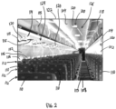
- Figure 2 illustrates a perspective view of a sanitizing system 100 within a portion of an internal cabin 122 of the aircraft 10 according to an example of the present disclosure.
- the internal cabin 122 includes outboard walls 102 connected to a ceiling 104. Windows 106 may be formed within the outboard walls 102.
- a floor 108 supports rows of seats 110.
- a row 112 may include three seats 110 on either side of an aisle 113. However, the row 112 may include more or less seats 110 than shown. Additionally, the internal cabin 122 may include more than the single aisle 113 shown in Figure 2 .
- Passenger service units (PSUs) 114 are secured between the outboard wall 302 and the ceiling 104 on either side of the aisle 113.
- the PSUs 114 are arranged in longitudinal columns that extend between a front end and rear end of the internal cabin 122.
- at least one PSU 114 may be positioned over the seats 110 within a row 112 on either side of the aisle 113.
- the PSUs 114 may include personal air blowers 115 (e.g., or vents, puffers, etc.), reading lights, oxygen bag drop panels, attendant request buttons, and other such controls and components. At least some of the controls and components of the PSU 114 may be shared between groups of two or three seats 110 in the row 112, such as the reading light. Other components may be specific to individual seats 110, such as the personal air blowers 115.
- Overhead stowage bin assemblies 118 are secured to the ceiling 104 and/or the outboard wall 102 above the PSU 114 on either side of the aisle 113.
- the overhead stowage bin assemblies 118 are secured over the seats 110.
- the overhead stowage bin assemblies 118 are configured to be pivoted open in order to receive passenger carry-on baggage and personal items, for example.
- the term "outboard” means a position that is further away from a central longitudinal plane of the internal cabin 122 as compared to another component
- the term “inboard” means a position that is closer to the central longitudinal plane of the internal cabin 122 as compared to another component.
- the sanitizing system 100 includes a plurality of ultraviolet (UV) lamps 120 mounted within the internal cabin 122.
- the UV lamps 120 are controlled to generate and emit UV light into the internal cabin 122 to sanitize and disinfect air and surfaces within the internal cabin 122.
- the UV lamps 120 may be located at various areas throughout the internal cabin 122.
- a first subset 124 of UV lamps 120 are mounted to the PSUs 114 above the passenger seats 110.
- the UV lamps 120 in the PSUs 114 may be disposed proximate to other components of the PSUs 114 such as the air blowers 115 and the reading lights.
- the UV lamps 120 in the first subset 124 are integrated into the PSUs 114 such that each UV lamp 120 emits UV light into an associated row 112 of seats 110 on one side of the aisle 113.
- each PSU 114 may include only one or multiple UV lamps 120.
- the field of illumination refers to refers to a three-dimensional volume in space that is defined by the propagation of UV light waves (e.g., rays) emitted by the UV lamp 120.
- the width of the field of illumination can depend on mechanical features of the UV lamp 120, such as reflectors, collimators, lenses, and the like, and optionally may be set to provide a predetermined width.
- the field of illumination of the UV lamps 120 in the PSUs 114 may be sufficient for each UV lamp 120 to sanitize the air and surfaces around two passenger seats 110.
- the PSU 114 may include at least two UV lamps 120 with one UV lamp 120 located outboard of another UV lamp 120 to enable the combined UV light to cover the entire group of seats 110 and the passengers seated thereon.
- the number of UV lamps 120 in the first subset 124 may match the total number of seats 110 such that each UV lamp 120 is specifically directed to and associated with a different seat 110 in the internal cabin 122.
- a second subset 126 of UV lamps 120 of the sanitizing system 100 is mounted to the ceiling 104 between the overhead stowage bin assemblies 118.
- the UV lamps 120 in the second subset 126 are aligned in a linear column that extends a length of the internal cabin 122 between the front and rear ends.
- the UV lamps 120 in the second subset 126 are spaced apart along the length.
- the spacing between the UV lamps 120 may be based on the field of illumination or spread of the UV light emitted from the UV lamps 120 to ensure that there is at least some overlap in the coverage areas of two adjacent UV lamps 120 at a designated height above the floor 108 to avoid creating dead zones that could harbor pathogens.
- the subset 126 may emit UV light that shines all the way down to the floor 108 within the aisle 113.
- the UV light from the subset 126 may essentially form a sanitization wall that partitions the internal cabin 122.
- the UV lamps 120 may be located in other areas of the cabin 122 as well, such as in galleys, in lavatories, at partitions between sections, and the like.
- the UV lamps 120 of the sanitizing system 100 are positioned throughout the cabin 122 to maximize the coverage area of the UV light. Maximizing the coverage area refers to emitting UV light to cover a substantial amount or percentage of the area or volume within the cabin 122, such as over 80%, over 90%, over 95%, or the like, particularly in areas occupied and trafficked by passengers and crew.
- the UV light sanitizes and disinfects the air and surrounding surfaces.
- the surrounding surfaces that can be disinfected by the UV light can include the seats 110 (including arm and headrests thereof), tray tables, personal computers used by the passengers, skin and clothing of the passengers and crew, walls of the cabin 122, doors, and the like.
- the sanitizing system 100 is configured to persistently operate the UV lamps 120 in the on, emitting state even in the presence of passengers, such as during boarding, taxiing, flight, and deboarding. Unlike current practices which only provide intermittent disinfection, such as chemically cleaning the cabin 122 between flights and filtering a given volume of air every time that volume of air is pulled through a return register of an environmental control system, the sanitizing system 100 disinfects pathogens on surfaces and in the air on a continuous basis.
- FIG 3 illustrates one of the UV lamps 120 of the sanitizing system 100 according to an example.
- the UV lamp 120 that is illustrated is in the PSU 114 above a seat 110 that is occupied by a passenger 130.
- the UV lamp 120 is located and oriented to sanitize contaminated air before that air touches and/or is inhaled by the passenger 130.
- the UV lamp 120 has a field of illumination 132 that encompasses the passenger's head 133, or at least face 134, when the passenger 130 is sitting in the seat 110 facing forward.
- air that is breathed by the passenger 130 travels through the UV light and is sanitized.
- the UV lamp 120 is positioned to emit UV light into a breathing area 136 in front of the passenger's face 134, which protects the passenger 130 from airborne pathogens, such as during conversations with other passengers and crew members.
- the illustrated example shows that the UV light is emitted into a flow path of air through the cabin 122.
- air from an environmental control system or air conditioning system is supplied into the cabin 122 via a supply vent 140 and a personal air blower (or vent) 115.
- the supply vent 140 may be disposed along a wall or ceiling of the cabin 122, such as above the stowage bin assemblies 118 shown in Figure 2 .
- the personal air blower 115 is a component of the PSU 114, and may have a manually adjustable damper to selectively regulate the direction and/or flow rate of air.
- a return register 142 or vent is configured to collect air from the cabin 122 and cycle the air back through the environmental control system. The return air may be filtered through at least one HEPA filter.
- the supply vent 140 and blower 115 are disposed above the seat 110, and the return register 142 is disposed below the seat 110, such as at or near the floor.
- the air through the cabin 122 generally flows downward from the supply vent 140 and the blower 115 to the return register 142.
- the UV lamp 120 directs UV light into the air flow path at a location between the passenger 130 and the supply vent 140 and/or blower 115.
- the UV lamp is controlled and/or the UV light is filtered to enable the passenger 130 to be exposed to the UV light for a prolonged period of time without harm to the passenger 130.
- the emitted UV light may have a designated wavelength or a narrow band of wavelengths experimentally determined to be harmless to human tissue through prolonged exposure.
- the UV lamp 120 may be configured or constructed to only generate the designated wavelength or the narrow band.
- a filter may be utilized that absorbs or dissipates wavelengths outside of the designated wavelength or the narrow band such that emitted UV light in the field of illumination 132 shown in Figure 3 only consists of the designated wavelength or the narrow band.
- the designated wavelength is 222 nm. It has been found that sanitizing UV light having a wavelength of 222 nm kills pathogens (such as viruses and bacteria), instead of inactivating pathogens. In contrast, UVC light at a wavelength of 254 nm inactivates pathogens by interfering with their DNA, resulting in temporary inactivation, but may not kill the pathogens. Instead, the pathogen may be reactivated by exposure to ordinary white light at a reactivation rate of 10% per hour (or about 10% per hour). As such, UVC light at a wavelength of 254 nm may be ineffective in illuminated areas, such as within an internal cabin of a vehicle.
- pathogens such as viruses and bacteria
- UVC light at 254 nm is not recommended for human exposure because it may be able to penetrate human cells.
- sanitizing UV light having a wavelength of 222 nm is safe for human exposure and kills pathogens.
- the sanitizing UV light having a wavelength of 222 nm may be emitted at full power within one millisecond or less of the UV lamps 120 being activated (in contrast the UVC light having a wavelength of 254 nm, which may take seconds or even minutes to reach full power).
- FIG. 4 illustrates a side view of one of the UV lamps 120 of the sanitizing system 100 according to an example.
- the UV lamp 120 includes a housing 150, a bulb 152, a cover sheet 154 or lens, and a reflector 156.
- the bulb 152 and the reflector 156 are held within a cavity 158 defined by the housing 150 and the cover sheet 154.
- the bulb 152 emits UV light that penetrates through the cover sheet 154, which is transparent or at least translucent, into the field of illumination 132.
- the reflector 156 is reflective and arranged such that the bulb 152 is between the reflector 156 and the cover sheet 154.
- the reflector 156 is shaped and positioned to reflect light that impinges on the surface of the reflector 156 towards the cover sheet 154.
- the reflector 156 may be curved at least partially around the bulb 152.
- the walls of the housing 150 may be opaque, and optionally reflective, to prevent light transmission through the walls, ensuring that the field of illumination 132 is defined by light transmitted through the cover sheet 154.
- the UV lamp 120 may include additional components, such as a convex lens or a concave lens, hardware for mounting the bulb 152 to the housing 150, and circuitry for supplying electrical power to the bulb 152.
- the field of illumination 132 is static and consistent during operation of the UV lamp 120.
- the reflector 156 may be mounted in a fixed position within the housing 150.
- the reflector 156 may be able to rotate or swivel to change the dimensions of the field of illumination 132.
- Figure 5 illustrates a side view of one of the UV lamps 120 of the sanitizing system 100 according to another example.
- the reflector 156 is coupled to an actuator that is controlled to swivel and/or translate the reflector 156 to change the angle of the reflector 156 relative to the bulb 152 and the cover sheet 154.
- the reflector 156 In the illustrated position, the reflector 156 is off-center to the right and the field of illumination 132 (shown in solid lines) is skewed to the left.
- the field of illumination 132 (not shown) shifts to the right.
- the UV light is transmitted into a wider illumination area 160 than the static lamp 120 shown in Figure 4 .
- the illumination area 160 represents the outermost edges of the field of illumination 132 through a full cycle of the moving reflector 156, such that the dashed line represents an edge when the reflector 156 is off-center to the left.
- the wider illumination area 160 can be provided by swiveling or rotating the entire housing 150 or a lens within the housing instead of moving the reflector 156.
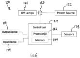
- FIG 6 is a schematic diagram of the sanitizing system 100 according to an example.
- the sanitizing system 100 includes the UV lamps 120, a control unit 170, a power source 172, an input device 174, an output device 176, and sensors 178.
- the sensors 178 are optional such that one or more examples may lack sensors.
- the sanitizing system 100 is disposed onboard the aircraft.
- the UV lamps 120 represent the multitude of UV lamps 120 throughout the internal cabin 122 as shown in Figure 2 , including the UV lamps 120 in the PSUs 114 and along the ceiling 104.
- the power source 172 provides electrical power to the UV lamps 120 to power the generation of UV light.
- the power source 172 may be a generator that converts mechanical energy to electrical energy.
- the UV lamps 120 may utilize the same power source 172 and conductive pathways that supply power to other components in the cabin 122, such as the lights and blowers 115 in the PSUs 114.
- the UV lamps 120 may plug into the same electronics package that controls cabin lighting.
- the control unit 170 is operatively connected to the UV lamps 120, the input device 174, the output device 176, and the sensors 178 via wired and/or wireless communication pathways.
- the control unit 170 generates control signals that control the operations of the UV lamps 120.
- the control unit 170 represents hardware circuitry that includes and/or is connected with one or more processors 182 (e.g., one or more microprocessors, integrated circuits, microcontrollers, field programmable gate arrays, etc.).
- the control unit includes and/or is connected with a tangible and non-transitory computer-readable storage medium (e.g., memory) 184.
- the memory 184 may store programmed instructions (e.g., software) that is executed by the one or more processors 182 to perform the operations of the control unit 170 described herein.
- the control unit 170 can control the UV lamps 120 by controlling the presence and amount of electrical power (e.g., voltage and current) that is supplied to each of the UV lamps 120.
- the control unit 170 is operatively connected to at least one switching device 180 along the circuit or bus between the power source 172 and the UV lamps 120.
- the switching device 180 is configured to selectively open (or break) a circuit to block power conduction to one or more of the UV lamps 120 and close (or establish) a circuit to enable power conduction to the one or more UV lamps 120.
- the switching device 180 may represent or include a solid-state relay, an electromechanical relay, an optical switch, a DC-DC converter, and/or the like.
- the sanitizing system 100 may include multiple switching devices 180 that are independently controlled by the control unit 170.
- each UV lamp 120 may have a different switching device 180 to enable independent control over each UV lamp 120.
- One or more of the switching devices 180 may enable variable control over the amount of power supplied to the associated UV lamps 120, besides merely turning the lamps 120 ON and OFF.
- at least one switching device 180 can be controlled to supply full power to the associated UV lamps 120 and one or more reduced power levels, such as a medium power level and a low power level.
- the input device 174 can represent or include a selector knob, a workstation computer, a tablet computer, a handheld computer (e.g., a smartphone), a keyboard, a touchpad, a joystick, and the like for enabling a pilot or another operator to control the sanitizing system 100.
- an operator can enter a user input via the input device 174 for turning the UV lamps 120 ON and OFF, for selecting a power setting for one or more of the UV lamps 120, and/or for selecting an activity setting that controls one or more of the UV lamps 120.
- the output device 176 can be an integrated display device onboard the aircraft and/or a display screen on a personal computer, tablet, or handheld computer (e.g., smartphone).
- the control unit 170 may generate control signals for controlling the output device 176 to display a notification indicating the operating status of the sanitizing system 100.
- the operating status can include whether the sanitizing system 100 is ON or OFF and the power setting or level of the UV lamps 120.
- the operating status show the status of different subgroups that may be operating at different power settings. For example, the operating status may show that a UV lamp 120 in the lavatory is OFF while the UV lamps 120 in the PSUs 114 (shown in Figure 2 ) are ON at a medium power setting.
- the sanitizing system 100 may be configured to automatically switch between different activity settings based on information received from the sensors 178 and/or other onboard systems.
- the activity settings can include boarding and deboarding, travel day, travel night, and OFF.
- the sanitizing system 100 may operate in the OFF setting at which the UV lamps 120 are turned off and no UV light is emitted.
- the OFF setting is energy efficient because the sanitizing system 100 does not draw power to generate UV light.
- the control unit 170 may determine that the cabin 122 is empty based on one or more factors, such as the aircraft environmental control system being in the OFF state, the engines 14 and/or auxiliary power unit being in the OFF state, and the door to the aircraft being closed and locked.
- the sensors 178 may include proximity sensors, motion sensors, and/or pressure sensors within the cabin 122.
- the sensors 178 may operate based on optical beams, passive infrared energy, microwave pulses, electrical induction, or the like.
- the control unit 170 may also determine that the cabin 122 is empty based on the proximity sensors, motion sensors, and/or pressure sensors indicating a lack of moving persons within the cabin 122.
- the control unit 170 operates the sanitizing system 100 in the boarding and deboarding setting.
- the UV lamps 120 are operated in a high power level.
- the UV lamps generate and emit UV light at a high power output (relative to other activity settings) such that the emitted UV light has a high intensity.
- the UV lamps provide a stronger dose (e.g., amount of UV radiation per unit time) in the high power level relative to other power levels.
- the stronger dose is provided because the passengers and crew members are highly active during boarding and deboarding, as the passengers enter (or leave) the cabin 122, walk through the aisle 113, stow (or retrieve) their luggage, find (or exit) seats 110, and talk to other passengers. Because the spread of pathogens is increased during high activity events, the UV lamps 120 are operated in the high or full power levels to kill as many pathogens as possible.
- the control unit 170 can automatically determine that the boarding and deboarding is occurring based on the door to the aircraft being open (as indicated by a sensor that monitors door position), the aircraft being stationary, the environmental control system operating, and the like.
- the proximity, motion, and/or pressure sensors 178 can be used to detect an amount of movement in the cabin 122 during boarding and deboarding events.
- the control unit 170 may automatically switch the sanitizing system 100 to the boarding and deboarding setting based on one or more of the factors above. For example, the control unit 170 may switch to the boarding and deboarding setting responsive to data or signals from the sensors 178 that indicate that a level or amount of movement in the cabin 122 exceeds a designated threshold activity level.
- an operator may utilize the input device 174 to manually instruct the control unit 170 which setting to implement, such as to instruct the control unit 170 to switch to the boarding and deboarding setting. Such manual control inputs may override the automated setting selection by the control unit 170.
- the control unit 170 may operate the sanitizing system 100 in the travel day setting.
- the travel day setting may represent a medium power level that is supplied to the UV lamps 120.
- the activity level during daytime travel is less than the activity level during boarding and deboarding.
- the UV lamps 120 are operated with the medium power level, instead of the high power level, to continue sanitizing the air with UV light while at the same time conserving some electrical energy relative to operating in the high power level.
- the control unit 170 can automatically switch to the daytime travel setting based on factors that indicate that the aircraft is in flight and that it is daytime.
- the factors that indicate flight can include altimeter data, velocity data, engine settings, and the like.
- the factors that indicate daytime can include a clock and/or an ambient light sensor. For example, if in flight and the time is after 7 AM and before 7 PM, the control unit 170 may switch to the daytime flight setting.
- the control unit 170 is configured to switch the sanitizing system 100 to a travel night setting.
- the travel night setting may represent a low power level.
- the UV lamps 120 remain ON and emitting UV light in the lower power level, but at a reduced intensity or concentration than in the medium and high power levels. The lower power level conserves more electrical energy than the medium and high power levels.
- the control unit 170 may switch to the travel night setting upon detecting that the aircraft is in flight and the time is after 7 PM and before 7 AM, for example.
- the high or full power level may supply 100% of the rated power of the UV lamps 120 to the UV lamps 120
- the medium power level may supply 50%, 60%, or 66% of the rated power to the UV lamps 120
- the low power level may supply 25%, 33%, or 40% of the rated power to the UV lamps 120.
- the one or more switching devices 180 may be utilized to appropriately step down the power delivered to the UV lamps 120.
- the sensors 178 may include individual sensors disposed in each row of seats and configured to detect the presence of passengers in the seats of that row.
- a proximity sensor may be installed in the PSU 114 that detects when a passenger is present on the seat 110 by the proximity of that person to the proximity sensor.
- the control unit 170 receives the sensor data from the sensors 178 and analyzes the data to determine if any seats 110 and/or entire rows 112 of seats 110 on either side of the aisle 113 are unoccupied.
- the control unit 170 may automatically reduce the power level supplied to the UV lamp 120 that is associated with that seat 110 by either turning the UV lamp 120 OFF or reducing to the low or medium power level. For example, the control unit 170 may reduce the power level of UV lamps 120 associated with unoccupied seats 110 one level below the current setting of the UV lamps 120 associated with occupied seats 110. Thus, if the current setting is the travel day setting with the UV lamps 120 in the medium power level, the control unit 170 controls the UV lamps 120 associated with unoccupied seats 110 in the low power level.
- a method for sanitizing and disinfecting air and surfaces within an internal cabin of a vehicle is provided.
- the method may be performed by the sanitizing system 100 described above with reference to Figures 1-6 . Certain steps of the method may be performed by the control unit 170 shown in Figure 6 based on programmed logic or instructions.
- the method optionally includes additional steps than described, fewer steps than described, and/or different steps than described.
- the method includes supplying electrical power from a power source 172 onboard a vehicle 10 to a plurality of ultraviolet (UV) lamps 120 mounted at various locations within an internal cabin 122 of the vehicle 10.
- the method also includes controlling the UV lamps 120 to emit UV light into the internal cabin 122 on a continuous basis during a trip of the vehicle 10.
- the UV lamps 120 are positioned such that the emitted UV light disinfects air within the internal cabin 122 before passengers in the internal cabin 122 breathe the air.
- controlling the UV lamps 120 to emit the UV light includes controlling the UV lamps 120 to emit the UV light at a designated wavelength or narrow wavelength range that is safe for human tissue at prolonged exposure.
- Supplying the electrical power to the UV lamps 120 may include supplying the electrical power at a first power level during boarding and deboarding of the passengers in the internal cabin 122 and supplying the electrical power at a second power level that is less than the first power level during travel (e.g., movement) of the vehicle 10, such as flight of an aircraft.
- examples of the present disclosure provide systems and a methods for sanitizing and disinfecting surfaces, air, and people within an internal cabin of a vehicle on a continuous basis via UV light without harming the people exposed to the UV light. Further, examples of the present disclosure provide built-in, easy-to-use, and safe systems and methods for using UV light to sanitize air and surfaces within an internal vehicle cabin.
- the sanitizing system 100 described with reference to Figures 1-6 disinfects pathogens in air and surfaces in aircraft cabin on a continuous basis.
- 222 nm UV light may be on continuously (according to a duty cycle controlled by flight regime and crew). This allows disinfection for that flight regime at controlled or limited power.
- the UV light may kill pathogens both in the air and on surfaces near the lamp.
- the 222 nm UV may not be harmful to human tissue, while at the same time may be effective at killing pathogens.
- continuous exposure of an aircraft zone to 222 nm UV would both reduce pathogens in that zone and cause no harm to human occupants.
- 222 nm UV lighting can be deployed in a modulated way according to flight regime to maintain a constant or increased level of disinfection presence.
- This 222 nm lighting will continuously sanitize both the air and the surfaces of the cabin, including tray tables, seats, computer screens, individuals clothing, individuals skin, etc.
- a structure, limitation, or element that is "configured to” perform a task or operation is particularly structurally formed, constructed, or adapted in a manner corresponding to the task or operation.
- an object that is merely capable of being modified to perform the task or operation is not “configured to” perform the task or operation as used herein.
- value modifiers such as “about,” “substantially,” and “approximately” inserted before a numerical value indicate that the value can represent other values within a designated threshold range above and/or below the specified value, such as values within 5%, 10%, or 15% of the specified value.
Landscapes
- Health & Medical Sciences (AREA)
- General Health & Medical Sciences (AREA)
- Epidemiology (AREA)
- Life Sciences & Earth Sciences (AREA)
- Animal Behavior & Ethology (AREA)
- Public Health (AREA)
- Veterinary Medicine (AREA)
- Engineering & Computer Science (AREA)
- Aviation & Aerospace Engineering (AREA)
- Mechanical Engineering (AREA)
- Pulmonology (AREA)
- Apparatus For Disinfection Or Sterilisation (AREA)
- Disinfection, Sterilisation Or Deodorisation Of Air (AREA)
Claims (15)
- Fahrzeug mit:einer Innenkabine; undeinem Desinfektionssystem (100) mit:einer Mehrzahl von Ultraviolett-Lampen, UV-Lampen (120), die an verschiedenen Stellen innerhalb der Innenkabine (122) des Fahrzeugs angebracht sind, wobei die UV-Lampen (120) konfiguriert sind, um elektrische Leistung von einer Stromquelle (172) an Bord des Fahrzeugs zu empfangen und während einer Reise des Fahrzeugs kontinuierlich UV-Licht in die Innenkabine (122) zu emittieren, wobei die UV-Lampen (120) so positioniert sind, dass das emittierte UV-Licht die Luft in der Innenkabine (122) desinfiziert; undeiner Steuereinheit (170) mit einem oder mehreren Prozessoren, wobei die Steuereinheit (170) mit den UV-Lampen (120) wirkverbunden ist; wobeidie Steuereinheit (170) konfiguriert ist, um eine oder mehrere der UV-Lampen (120) auf einem ersten Leistungspegel zu betreiben, wenn die Steuereinheit (170) feststellt, dass Passagiere in die Innenkabine (122) einsteigen oder aus ihr aussteigen.
- Fahrzeug nach Anspruch 1, bei dem die verschiedenen Positionen der UV-Lampen (120) Positionen sind, die während der Reise von Passagieren und Besatzungsmitgliedern eingenommen werden.
- Fahrzeug nach Anspruch 1 oder 2, bei dem eine Teilmenge (126) der UV-Lampen (120) an einer Decke (104) der Innenkabine (122) angebracht und entlang einer Länge der Innenkabine (122) voneinander beabstandet sind, wobei die Teilmenge (126) konfiguriert ist, um UV-Licht von der Decke (104) bis zu einem Boden (108) eines Ganges (113) zu emittieren.
- Fahrzeug nach Anspruch 1, 2 oder 3, bei dem eine Teilmenge (126) der UV-Lampen (120) in Passagier-Serviceeinheiten, PSUs (114) integriert ist, die über jeder Reihe (112) von mehreren Reihen (112) von Sitzen (110) angeordnet sind, wobei die PSUs (114) auch persönliche Luftgebläse (115) umfassen.
- Fahrzeug nach einem der Ansprüche 1 bis 4, bei dem die UV-Lampen (120) konfiguriert sind, um das UV-Licht bei einer bestimmten Wellenlänge oder in einem schmalen (112) Wellenlängenbereich zu emittieren, der für menschliches Gewebe sicher ist, und wobei die bestimmte Wellenlänge optional 222 nm beträgt.
- Fahrzeug nach einem der Ansprüche 1 bis 5, bei dem die UV-Lampen (120) gesteuert sind, um das UV-Licht während der gesamten Dauer der Reise dauerhaft zu emittieren.
- Fahrzeug nach Anspruch 1, bei dem die Steuereinheit (170) konfiguriert ist, um die elektrische Leistung, die einer oder mehreren der UV-Lampen (120) während der Reise zugeführt wird, auf der Grundlage der Aktivität der Passagiere so zu modifizieren, dass die eine oder mehreren UV-Lampen (120) mehr elektrische Leistung erhalten, wenn die Passagiere aktiver sind, als wenn die Passagiere weniger aktiv sind.
- Fahrzeug nach Anspruch 1 oder 7, bei dem das Desinfektionssystem (100) ferner eine Eingabeeinrichtung (174) umfasst, die Steuereinheit (170) betriebsmäßig mit der Eingabeeinrichtung (174) verbunden ist, und die Steuereinheit (170) konfiguriert ist, um die einer oder mehreren der UV-Lampen (120) zugeführte elektrische Leistung basierend auf einem von der Eingabevorrichtung (174) empfangenen, eine manuelle Auswahl eines Bedieners anzeigenden Steuersignal zu modifizieren.
- Fahrzeug nach Anspruch 1, bei dem die Steuereinheit (170) konfiguriert ist, um die eine oder mehreren UV-Lampen (120) auf einem zweiten Leistungspegel zu betreiben, der niedriger ist als der erste Leistungspegel, wenn festgestellt wird, dass das Fahrzeug in Bewegung ist.
- Fahrzeug nach einem der Ansprüche 1 oder 6-9, bei dem die Steuereinheit (170) konfiguriert ist, um eine oder mehrere der UV-Lampen (120) auf einem zweiten Leistungspegel zu betreiben, wenn festgestellt wird, dass das Fahrzeug tagsüber in Bewegung ist, und konfiguriert ist, um die eine oder mehreren UV-Lampen (120) auf einem dritten Leistungspegel zu betreiben, der niedriger ist als der zweite Leistungspegel, wenn festgestellt wird, dass das Fahrzeug nachts in Bewegung ist.
- Fahrzeug nach einem der Ansprüche 1 oder 6-10, das ferner eine Mehrzahl von Sensoren (178) umfasst, die verschiedenen Sitzen (110) in der Innenkabine (122) zugeordnet sind, wobei die Steuereinheit (170) mit den Sensoren (178) wirkverbunden ist, wobei die Steuereinheit (170) konfiguriert ist, um eine UV-Lampe der UV-Lampen (120) zu steuern, um als Reaktion auf die Feststellung, basierend auf einem von einem Sensor der Sensoren (178) empfangenen Signal, dass der dem einen Sensor zugeordnete Sitz unbesetzt ist, die der dem Sitz (110) zugeordneten UV-Lampe (120) zugeführte Leistung auf einen niedrigen oder mittleren Leistungspegel zu reduzieren.
- Fahrzeug nach einem der Ansprüche 1-11, bei dem mindestens einige der UV-Lampen (120) angeordnet sind, um das UV-Licht in ein Beleuchtungsfeld (132) zu emittieren, das sich zwischen einer Luftzufuhröffnung (140) oder einem persönlichen Luftgebläse (115) und den jeweiligen Passagieren in Sitzen in der Innenkabine (122) erstreckt, so dass das UV-Licht die aus der Luftzufuhröffnung (140) oder dem persönlichen Luftgebläse (115) ausgestoßene Luft desinfiziert, bevor die Passagiere in den Sitzen die Luft einatmen.
- Fahrzeug nach einem der Ansprüche 1-12, wobei das Fahrzeug ein Flugzeug ist.
- Verfahren mit den Schritten:Zuführen von elektrischer Leistung von einer Stromquelle (172) an Bord eines Fahrzeugs, optional eines Flugzeugs, zu einer Mehrzahl von Ultraviolett-, UV-, Lampen (120), die an verschiedenen Stellen innerhalb einer Innenkabine (122) des Fahrzeugs angebracht sind; undSteuern der UV-Lampen (120), um während einer Reise des Fahrzeugs kontinuierlich UV-Licht in die Innenkabine (122) zu emittieren, wobei die UV-Lampen (120) so positioniert sind, dass das emittierte UV-Licht die Luft in der Innenkabine (122) desinfiziert, bevor die Passagiere in der Innenkabine (122) die Luft einatmen; wobeidas Zuführen der elektrischen Leistung zu den UV-Lampen (120) das Zuführen der elektrischen Leistung auf einem ersten Leistungspegel während des Ein- und Aussteigens der Passagiere in der Innenkabine (122) umfasst, in Reaktion darauf, dass eine Steuereinheit (170) feststellt, dass die Passagiere in die Innenkabine (122) ein- oder aus ihr aussteigen.
- Verfahren nach Anspruch 14, bei dem das Zuführen der elektrischen Leistung zu den UV-Lampen (120) das Zuführen der elektrischen Leistung während der Reise des Fahrzeugs bei einem zweiten Leistungspegel umfasst, der niedriger ist als der erste Leistungspegel.
Applications Claiming Priority (2)
| Application Number | Priority Date | Filing Date | Title |
|---|---|---|---|
| US202063042898P | 2020-06-23 | 2020-06-23 | |
| US17/352,724 US12133926B2 (en) | 2020-06-23 | 2021-06-21 | Sanitizing system |
Publications (2)
| Publication Number | Publication Date |
|---|---|
| EP3929084A1 EP3929084A1 (de) | 2021-12-29 |
| EP3929084B1 true EP3929084B1 (de) | 2024-11-06 |
Family
ID=76584369
Family Applications (1)
| Application Number | Title | Priority Date | Filing Date |
|---|---|---|---|
| EP21181076.7A Active EP3929084B1 (de) | 2020-06-23 | 2021-06-23 | Desinfektionssystem |
Country Status (4)
| Country | Link |
|---|---|
| US (1) | US12133926B2 (de) |
| EP (1) | EP3929084B1 (de) |
| JP (1) | JP7695121B2 (de) |
| CN (1) | CN113827760A (de) |
Families Citing this family (13)
| Publication number | Priority date | Publication date | Assignee | Title |
|---|---|---|---|---|
| EP3766781B1 (de) * | 2019-07-14 | 2024-05-15 | Goodrich Lighting Systems GmbH | Fahrgastsitzüberdachung |
| US11427326B2 (en) * | 2020-02-27 | 2022-08-30 | Mirza Faizan | Automated aircraft tray table disinfecting system using ultra-violet light |
| US11730844B1 (en) | 2020-12-18 | 2023-08-22 | Zoox, Inc. | Method of disinfecting vehicle using UVC light emitters |
| US11931472B1 (en) * | 2020-12-18 | 2024-03-19 | Zoox, Inc. | Vehicle with UVC light emitters |
| EP4029532B1 (de) * | 2021-01-05 | 2025-12-03 | The Boeing Company | Ultraviolette vorrichtung und verwendungsverfahren dafür |
| JP2022167486A (ja) * | 2021-04-23 | 2022-11-04 | トヨタ自動車株式会社 | 車両運用システム及び自動運転車両 |
| US11851187B2 (en) * | 2021-08-19 | 2023-12-26 | Goodrich Corporation | Seat light systems and methods for aircraft cabins |
| FR3127175B1 (fr) * | 2021-09-20 | 2024-12-13 | Alstom Transp Tech | Véhicule comprenant un système de désinfection |
| US11833263B2 (en) | 2022-02-17 | 2023-12-05 | Kart Kleen, LLC | Mobile device for object disinfection and/or sanitization |
| KR20230143683A (ko) | 2022-04-06 | 2023-10-13 | 현대자동차주식회사 | 살균 장치 |
| US20230364281A1 (en) * | 2022-05-16 | 2023-11-16 | Oxti Pte Ltd | Chair sterilization device |
| CN115554433B (zh) * | 2022-10-09 | 2023-11-17 | 中国商用飞机有限责任公司 | 客舱消毒系统、客舱消毒方法和载运工具 |
| US20250196574A1 (en) * | 2023-12-13 | 2025-06-19 | GM Global Technology Operations LLC | Vehicle interior climate control based on occupancy |
Family Cites Families (20)
| Publication number | Priority date | Publication date | Assignee | Title |
|---|---|---|---|---|
| CN2693240Y (zh) * | 2004-03-23 | 2005-04-20 | 常剑 | 车用消毒装置 |
| US7878586B2 (en) * | 2007-10-29 | 2011-02-01 | The Boeing Company | System and method for an anticipatory passenger cabin |
| US10029797B2 (en) | 2008-09-30 | 2018-07-24 | The Boeing Company | Personal ventilation in an aircraft environment |
| WO2016196904A1 (en) * | 2015-06-03 | 2016-12-08 | The Trustees Of Columbia University In The City Of New York | Apparatus, method and system for selectively affecting and/or killing a virus |
| US9511159B2 (en) * | 2014-07-02 | 2016-12-06 | At&T Intellectual Property I, L.P. | Method and apparatus for sterilizing a surface |
| US20170080117A1 (en) | 2014-07-16 | 2017-03-23 | LiteProducts LLC | System and method for inactivating pathogens using visible light and/or uv light |
| DE112015004376T5 (de) | 2014-09-26 | 2017-06-08 | Mag Aerospace Industries, Llc | Systeme und Verfahren zum Behandeln von Kabinenoberflächen und Luft |
| US10195300B2 (en) * | 2016-02-25 | 2019-02-05 | Ralph Birchard Lloyd | System and method for disinfecting an occupied area using germicidal radiation based on eye protection worn by persons in the area |
| JP2018007804A (ja) | 2016-07-13 | 2018-01-18 | 株式会社トクヤマ | キャビン内空気清浄装置 |
| KR20180056928A (ko) * | 2016-11-21 | 2018-05-30 | 엘에스오토모티브테크놀로지스 주식회사 | 차량용 룸램프 유닛 및 그 제어방법 |
| US10655818B2 (en) | 2017-01-24 | 2020-05-19 | The Boeing Company | Light-converting lighting assembly |
| US10864849B2 (en) * | 2017-03-10 | 2020-12-15 | The Boeing Company | Illuminated stowage bin assemblies within vehicles |
| US10130727B1 (en) * | 2017-06-26 | 2018-11-20 | The Boeing Company | Systems and methods for operating a light system |
| GB201715458D0 (en) * | 2017-07-28 | 2017-11-08 | Airbus Sas | Aircraft Cabin Disinfection System |
| EP3691972B1 (de) | 2017-10-06 | 2024-02-21 | Bombardier Inc. | Verfahren zur desinfektion einer flugzeugkabine unter verwendung einer beleuchtungsanordnung und beleuchtungsanordnung dafür |
| US10265428B1 (en) * | 2017-10-06 | 2019-04-23 | The Boeing Company | Reflector system for a lighting assembly |
| AU2019242574B2 (en) * | 2018-03-30 | 2021-12-09 | Uv Partners, Inc. | Disinfection behavior tracking and ranking |
| US10866484B2 (en) * | 2018-09-04 | 2020-12-15 | Abl Ip Holding Llc | Light frequency upconversion of laser light, for cleansing |
| CN111110890A (zh) | 2020-03-23 | 2020-05-08 | 重庆瓦力仪器有限公司 | 一种车辆内部杀菌系统 |
| DE202020001197U1 (de) * | 2020-03-26 | 2020-04-15 | Digitalicht Ag | Beleuchtungsvorrichtung mit integrierter UVCStrahlungsquelle |
-
2021
- 2021-06-21 US US17/352,724 patent/US12133926B2/en active Active
- 2021-06-23 JP JP2021104080A patent/JP7695121B2/ja active Active
- 2021-06-23 EP EP21181076.7A patent/EP3929084B1/de active Active
- 2021-06-23 CN CN202110698715.9A patent/CN113827760A/zh active Pending
Also Published As
| Publication number | Publication date |
|---|---|
| CN113827760A (zh) | 2021-12-24 |
| JP7695121B2 (ja) | 2025-06-18 |
| JP2022002700A (ja) | 2022-01-11 |
| EP3929084A1 (de) | 2021-12-29 |
| US20210393823A1 (en) | 2021-12-23 |
| US12133926B2 (en) | 2024-11-05 |
Similar Documents
| Publication | Publication Date | Title |
|---|---|---|
| EP3929084B1 (de) | Desinfektionssystem | |
| EP3929085B1 (de) | Desinfektionssystem | |
| EP3929087B1 (de) | Ultraviolettlichtabschirmsystem | |
| EP3915596B1 (de) | Stufensteuerungssysteme und verfahren zur desinfektion mit ultraviolettem licht | |
| EP3449948B1 (de) | Ozonzerstörende ultraviolettlichtreinigungssysteme und verfahren | |
| EP3691972B1 (de) | Verfahren zur desinfektion einer flugzeugkabine unter verwendung einer beleuchtungsanordnung und beleuchtungsanordnung dafür | |
| US10159761B2 (en) | Sanitizing surfaces | |
| US20150209459A1 (en) | Sanitizing surfaces associated with aircraft areas | |
| US20150209460A1 (en) | Sanitizing surfaces associated with assembly areas | |
| JP7706267B2 (ja) | 可視光殺菌システム及び方法 | |
| EP3922276B1 (de) | Stufensteuerungssysteme und verfahren zur desinfektion mit ultraviolettem licht | |
| EP3925630B1 (de) | Tragbare hygienisierungssysteme und verfahren mit reichweitenführung | |
| KR20150045628A (ko) | 살충 및 살균 기능을 포함하는 좌석 시스템 | |
| JP7697829B2 (ja) | 紫外線光遮蔽システム | |
| WO2016164364A1 (en) | Sanitizing surfaces | |
| JP7743211B2 (ja) | 電力管理システム | |
| CN114533912B (zh) | 调制的紫外线光消毒系统 | |
| EP4019412A1 (de) | Flugzeugdesinfizierungssystem für verstaubare artikel | |
| JP2022094420A (ja) | 不活化装置および不活化方法 | |
| USRE49580E1 (en) | Sanitizing surfaces |
Legal Events
| Date | Code | Title | Description |
|---|---|---|---|
| PUAI | Public reference made under article 153(3) epc to a published international application that has entered the european phase |
Free format text: ORIGINAL CODE: 0009012 |
|
| STAA | Information on the status of an ep patent application or granted ep patent |
Free format text: STATUS: THE APPLICATION HAS BEEN PUBLISHED |
|
| AK | Designated contracting states |
Kind code of ref document: A1 Designated state(s): AL AT BE BG CH CY CZ DE DK EE ES FI FR GB GR HR HU IE IS IT LI LT LU LV MC MK MT NL NO PL PT RO RS SE SI SK SM TR |
|
| B565 | Issuance of search results under rule 164(2) epc |
Effective date: 20211109 |
|
| STAA | Information on the status of an ep patent application or granted ep patent |
Free format text: STATUS: REQUEST FOR EXAMINATION WAS MADE |
|
| 17P | Request for examination filed |
Effective date: 20220628 |
|
| RBV | Designated contracting states (corrected) |
Designated state(s): AL AT BE BG CH CY CZ DE DK EE ES FI FR GB GR HR HU IE IS IT LI LT LU LV MC MK MT NL NO PL PT RO RS SE SI SK SM TR |
|
| RAP3 | Party data changed (applicant data changed or rights of an application transferred) |
Owner name: THE BOEING COMPANY |
|
| STAA | Information on the status of an ep patent application or granted ep patent |
Free format text: STATUS: EXAMINATION IS IN PROGRESS |
|
| 17Q | First examination report despatched |
Effective date: 20230419 |
|
| GRAP | Despatch of communication of intention to grant a patent |
Free format text: ORIGINAL CODE: EPIDOSNIGR1 |
|
| STAA | Information on the status of an ep patent application or granted ep patent |
Free format text: STATUS: GRANT OF PATENT IS INTENDED |
|
| RIC1 | Information provided on ipc code assigned before grant |
Ipc: A61L 2/10 20060101ALN20240517BHEP Ipc: B61D 29/00 20060101ALI20240517BHEP Ipc: B64D 13/00 20060101ALI20240517BHEP Ipc: A61L 9/20 20060101ALI20240517BHEP Ipc: B64D 11/00 20060101AFI20240517BHEP |
|
| INTG | Intention to grant announced |
Effective date: 20240625 |
|
| P01 | Opt-out of the competence of the unified patent court (upc) registered |
Free format text: CASE NUMBER: APP_41187/2024 Effective date: 20240711 |
|
| GRAS | Grant fee paid |
Free format text: ORIGINAL CODE: EPIDOSNIGR3 |
|
| GRAA | (expected) grant |
Free format text: ORIGINAL CODE: 0009210 |
|
| STAA | Information on the status of an ep patent application or granted ep patent |
Free format text: STATUS: THE PATENT HAS BEEN GRANTED |
|
| AK | Designated contracting states |
Kind code of ref document: B1 Designated state(s): AL AT BE BG CH CY CZ DE DK EE ES FI FR GB GR HR HU IE IS IT LI LT LU LV MC MK MT NL NO PL PT RO RS SE SI SK SM TR |
|
| REG | Reference to a national code |
Ref country code: GB Ref legal event code: FG4D |
|
| REG | Reference to a national code |
Ref country code: CH Ref legal event code: EP |
|
| REG | Reference to a national code |
Ref country code: DE Ref legal event code: R096 Ref document number: 602021021274 Country of ref document: DE |
|
| REG | Reference to a national code |
Ref country code: IE Ref legal event code: FG4D |
|
| REG | Reference to a national code |
Ref country code: LT Ref legal event code: MG9D |
|
| REG | Reference to a national code |
Ref country code: NL Ref legal event code: MP Effective date: 20241106 |
|
| PG25 | Lapsed in a contracting state [announced via postgrant information from national office to epo] |
Ref country code: PT Free format text: LAPSE BECAUSE OF FAILURE TO SUBMIT A TRANSLATION OF THE DESCRIPTION OR TO PAY THE FEE WITHIN THE PRESCRIBED TIME-LIMIT Effective date: 20250306 Ref country code: HR Free format text: LAPSE BECAUSE OF FAILURE TO SUBMIT A TRANSLATION OF THE DESCRIPTION OR TO PAY THE FEE WITHIN THE PRESCRIBED TIME-LIMIT Effective date: 20241106 Ref country code: IS Free format text: LAPSE BECAUSE OF FAILURE TO SUBMIT A TRANSLATION OF THE DESCRIPTION OR TO PAY THE FEE WITHIN THE PRESCRIBED TIME-LIMIT Effective date: 20250306 |
|
| PG25 | Lapsed in a contracting state [announced via postgrant information from national office to epo] |
Ref country code: FI Free format text: LAPSE BECAUSE OF FAILURE TO SUBMIT A TRANSLATION OF THE DESCRIPTION OR TO PAY THE FEE WITHIN THE PRESCRIBED TIME-LIMIT Effective date: 20241106 Ref country code: NL Free format text: LAPSE BECAUSE OF FAILURE TO SUBMIT A TRANSLATION OF THE DESCRIPTION OR TO PAY THE FEE WITHIN THE PRESCRIBED TIME-LIMIT Effective date: 20241106 |
|
| REG | Reference to a national code |
Ref country code: AT Ref legal event code: MK05 Ref document number: 1739137 Country of ref document: AT Kind code of ref document: T Effective date: 20241106 |
|
| PG25 | Lapsed in a contracting state [announced via postgrant information from national office to epo] |
Ref country code: BG Free format text: LAPSE BECAUSE OF FAILURE TO SUBMIT A TRANSLATION OF THE DESCRIPTION OR TO PAY THE FEE WITHIN THE PRESCRIBED TIME-LIMIT Effective date: 20241106 |
|
| PG25 | Lapsed in a contracting state [announced via postgrant information from national office to epo] |
Ref country code: ES Free format text: LAPSE BECAUSE OF FAILURE TO SUBMIT A TRANSLATION OF THE DESCRIPTION OR TO PAY THE FEE WITHIN THE PRESCRIBED TIME-LIMIT Effective date: 20241106 |
|
| PG25 | Lapsed in a contracting state [announced via postgrant information from national office to epo] |
Ref country code: NO Free format text: LAPSE BECAUSE OF FAILURE TO SUBMIT A TRANSLATION OF THE DESCRIPTION OR TO PAY THE FEE WITHIN THE PRESCRIBED TIME-LIMIT Effective date: 20250206 |
|
| PG25 | Lapsed in a contracting state [announced via postgrant information from national office to epo] |
Ref country code: LV Free format text: LAPSE BECAUSE OF FAILURE TO SUBMIT A TRANSLATION OF THE DESCRIPTION OR TO PAY THE FEE WITHIN THE PRESCRIBED TIME-LIMIT Effective date: 20241106 Ref country code: GR Free format text: LAPSE BECAUSE OF FAILURE TO SUBMIT A TRANSLATION OF THE DESCRIPTION OR TO PAY THE FEE WITHIN THE PRESCRIBED TIME-LIMIT Effective date: 20250207 Ref country code: AT Free format text: LAPSE BECAUSE OF FAILURE TO SUBMIT A TRANSLATION OF THE DESCRIPTION OR TO PAY THE FEE WITHIN THE PRESCRIBED TIME-LIMIT Effective date: 20241106 |
|
| PG25 | Lapsed in a contracting state [announced via postgrant information from national office to epo] |
Ref country code: PL Free format text: LAPSE BECAUSE OF FAILURE TO SUBMIT A TRANSLATION OF THE DESCRIPTION OR TO PAY THE FEE WITHIN THE PRESCRIBED TIME-LIMIT Effective date: 20241106 |
|
| PG25 | Lapsed in a contracting state [announced via postgrant information from national office to epo] |
Ref country code: RS Free format text: LAPSE BECAUSE OF FAILURE TO SUBMIT A TRANSLATION OF THE DESCRIPTION OR TO PAY THE FEE WITHIN THE PRESCRIBED TIME-LIMIT Effective date: 20250206 |
|
| PG25 | Lapsed in a contracting state [announced via postgrant information from national office to epo] |
Ref country code: SM Free format text: LAPSE BECAUSE OF FAILURE TO SUBMIT A TRANSLATION OF THE DESCRIPTION OR TO PAY THE FEE WITHIN THE PRESCRIBED TIME-LIMIT Effective date: 20241106 |
|
| PGFP | Annual fee paid to national office [announced via postgrant information from national office to epo] |
Ref country code: DE Payment date: 20250627 Year of fee payment: 5 |
|
| PG25 | Lapsed in a contracting state [announced via postgrant information from national office to epo] |
Ref country code: DK Free format text: LAPSE BECAUSE OF FAILURE TO SUBMIT A TRANSLATION OF THE DESCRIPTION OR TO PAY THE FEE WITHIN THE PRESCRIBED TIME-LIMIT Effective date: 20241106 |
|
| PGFP | Annual fee paid to national office [announced via postgrant information from national office to epo] |
Ref country code: GB Payment date: 20250627 Year of fee payment: 5 |
|
| PG25 | Lapsed in a contracting state [announced via postgrant information from national office to epo] |
Ref country code: EE Free format text: LAPSE BECAUSE OF FAILURE TO SUBMIT A TRANSLATION OF THE DESCRIPTION OR TO PAY THE FEE WITHIN THE PRESCRIBED TIME-LIMIT Effective date: 20241106 |
|
| PGFP | Annual fee paid to national office [announced via postgrant information from national office to epo] |
Ref country code: FR Payment date: 20250625 Year of fee payment: 5 |
|
| PG25 | Lapsed in a contracting state [announced via postgrant information from national office to epo] |
Ref country code: RO Free format text: LAPSE BECAUSE OF FAILURE TO SUBMIT A TRANSLATION OF THE DESCRIPTION OR TO PAY THE FEE WITHIN THE PRESCRIBED TIME-LIMIT Effective date: 20241106 |
|
| PG25 | Lapsed in a contracting state [announced via postgrant information from national office to epo] |
Ref country code: SK Free format text: LAPSE BECAUSE OF FAILURE TO SUBMIT A TRANSLATION OF THE DESCRIPTION OR TO PAY THE FEE WITHIN THE PRESCRIBED TIME-LIMIT Effective date: 20241106 |
|
| PG25 | Lapsed in a contracting state [announced via postgrant information from national office to epo] |
Ref country code: CZ Free format text: LAPSE BECAUSE OF FAILURE TO SUBMIT A TRANSLATION OF THE DESCRIPTION OR TO PAY THE FEE WITHIN THE PRESCRIBED TIME-LIMIT Effective date: 20241106 |
|
| PG25 | Lapsed in a contracting state [announced via postgrant information from national office to epo] |
Ref country code: IT Free format text: LAPSE BECAUSE OF FAILURE TO SUBMIT A TRANSLATION OF THE DESCRIPTION OR TO PAY THE FEE WITHIN THE PRESCRIBED TIME-LIMIT Effective date: 20241106 |
|
| REG | Reference to a national code |
Ref country code: DE Ref legal event code: R097 Ref document number: 602021021274 Country of ref document: DE |
|
| PG25 | Lapsed in a contracting state [announced via postgrant information from national office to epo] |
Ref country code: SE Free format text: LAPSE BECAUSE OF FAILURE TO SUBMIT A TRANSLATION OF THE DESCRIPTION OR TO PAY THE FEE WITHIN THE PRESCRIBED TIME-LIMIT Effective date: 20241106 |
|
| PLBE | No opposition filed within time limit |
Free format text: ORIGINAL CODE: 0009261 |
|
| STAA | Information on the status of an ep patent application or granted ep patent |
Free format text: STATUS: NO OPPOSITION FILED WITHIN TIME LIMIT |
|
| 26N | No opposition filed |
Effective date: 20250807 |
|
| REG | Reference to a national code |
Ref country code: CH Ref legal event code: H13 Free format text: ST27 STATUS EVENT CODE: U-0-0-H10-H13 (AS PROVIDED BY THE NATIONAL OFFICE) Effective date: 20260127 |
|
| PG25 | Lapsed in a contracting state [announced via postgrant information from national office to epo] |
Ref country code: MC Free format text: LAPSE BECAUSE OF FAILURE TO SUBMIT A TRANSLATION OF THE DESCRIPTION OR TO PAY THE FEE WITHIN THE PRESCRIBED TIME-LIMIT Effective date: 20241106 |
|
| PG25 | Lapsed in a contracting state [announced via postgrant information from national office to epo] |
Ref country code: LU Free format text: LAPSE BECAUSE OF NON-PAYMENT OF DUE FEES Effective date: 20250623 |
|
| REG | Reference to a national code |
Ref country code: BE Ref legal event code: MM Effective date: 20250630 |
|
| PG25 | Lapsed in a contracting state [announced via postgrant information from national office to epo] |
Ref country code: IE Free format text: LAPSE BECAUSE OF NON-PAYMENT OF DUE FEES Effective date: 20250623 |
|
| PG25 | Lapsed in a contracting state [announced via postgrant information from national office to epo] |
Ref country code: BE Free format text: LAPSE BECAUSE OF NON-PAYMENT OF DUE FEES Effective date: 20250630 |
|
| PG25 | Lapsed in a contracting state [announced via postgrant information from national office to epo] |
Ref country code: CH Free format text: LAPSE BECAUSE OF NON-PAYMENT OF DUE FEES Effective date: 20250630 |