EP3450327A1 - Station de soudage ainsi que procédé de fabrication d'emballage blister pourvu d'un angle d'arrachage - Google Patents
Station de soudage ainsi que procédé de fabrication d'emballage blister pourvu d'un angle d'arrachage Download PDFInfo
- Publication number
- EP3450327A1 EP3450327A1 EP17188571.8A EP17188571A EP3450327A1 EP 3450327 A1 EP3450327 A1 EP 3450327A1 EP 17188571 A EP17188571 A EP 17188571A EP 3450327 A1 EP3450327 A1 EP 3450327A1
- Authority
- EP
- European Patent Office
- Prior art keywords
- jaw
- cutting
- lid
- sealing
- packaging
- Prior art date
- Legal status (The legal status is an assumption and is not a legal conclusion. Google has not performed a legal analysis and makes no representation as to the accuracy of the status listed.)
- Granted
Links
Images



Classifications
-
- B—PERFORMING OPERATIONS; TRANSPORTING
- B65—CONVEYING; PACKING; STORING; HANDLING THIN OR FILAMENTARY MATERIAL
- B65B—MACHINES, APPARATUS OR DEVICES FOR, OR METHODS OF, PACKAGING ARTICLES OR MATERIALS; UNPACKING
- B65B61/00—Auxiliary devices, not otherwise provided for, for operating on sheets, blanks, webs, binding material, containers or packages
- B65B61/04—Auxiliary devices, not otherwise provided for, for operating on sheets, blanks, webs, binding material, containers or packages for severing webs, or for separating joined packages
- B65B61/06—Auxiliary devices, not otherwise provided for, for operating on sheets, blanks, webs, binding material, containers or packages for severing webs, or for separating joined packages by cutting
-
- B—PERFORMING OPERATIONS; TRANSPORTING
- B65—CONVEYING; PACKING; STORING; HANDLING THIN OR FILAMENTARY MATERIAL
- B65D—CONTAINERS FOR STORAGE OR TRANSPORT OF ARTICLES OR MATERIALS, e.g. BAGS, BARRELS, BOTTLES, BOXES, CANS, CARTONS, CRATES, DRUMS, JARS, TANKS, HOPPERS, FORWARDING CONTAINERS; ACCESSORIES, CLOSURES, OR FITTINGS THEREFOR; PACKAGING ELEMENTS; PACKAGES
- B65D81/00—Containers, packaging elements, or packages, for contents presenting particular transport or storage problems, or adapted to be used for non-packaging purposes after removal of contents
- B65D81/18—Containers, packaging elements, or packages, for contents presenting particular transport or storage problems, or adapted to be used for non-packaging purposes after removal of contents providing specific environment for contents, e.g. temperature above or below ambient
- B65D81/20—Containers, packaging elements, or packages, for contents presenting particular transport or storage problems, or adapted to be used for non-packaging purposes after removal of contents providing specific environment for contents, e.g. temperature above or below ambient under vacuum or superatmospheric pressure, or in a special atmosphere, e.g. of inert gas
- B65D81/2069—Containers, packaging elements, or packages, for contents presenting particular transport or storage problems, or adapted to be used for non-packaging purposes after removal of contents providing specific environment for contents, e.g. temperature above or below ambient under vacuum or superatmospheric pressure, or in a special atmosphere, e.g. of inert gas in a special atmosphere
- B65D81/2076—Containers, packaging elements, or packages, for contents presenting particular transport or storage problems, or adapted to be used for non-packaging purposes after removal of contents providing specific environment for contents, e.g. temperature above or below ambient under vacuum or superatmospheric pressure, or in a special atmosphere, e.g. of inert gas in a special atmosphere in an at least partially rigid container
-
- B—PERFORMING OPERATIONS; TRANSPORTING
- B26—HAND CUTTING TOOLS; CUTTING; SEVERING
- B26D—CUTTING; DETAILS COMMON TO MACHINES FOR PERFORATING, PUNCHING, CUTTING-OUT, STAMPING-OUT OR SEVERING
- B26D7/00—Details of apparatus for cutting, cutting-out, stamping-out, punching, perforating, or severing by means other than cutting
- B26D7/26—Means for mounting or adjusting the cutting member; Means for adjusting the stroke of the cutting member
- B26D7/2614—Means for mounting the cutting member
-
- B—PERFORMING OPERATIONS; TRANSPORTING
- B29—WORKING OF PLASTICS; WORKING OF SUBSTANCES IN A PLASTIC STATE IN GENERAL
- B29C—SHAPING OR JOINING OF PLASTICS; SHAPING OF MATERIAL IN A PLASTIC STATE, NOT OTHERWISE PROVIDED FOR; AFTER-TREATMENT OF THE SHAPED PRODUCTS, e.g. REPAIRING
- B29C65/00—Joining or sealing of preformed parts, e.g. welding of plastics materials; Apparatus therefor
- B29C65/02—Joining or sealing of preformed parts, e.g. welding of plastics materials; Apparatus therefor by heating, with or without pressure
-
- B—PERFORMING OPERATIONS; TRANSPORTING
- B29—WORKING OF PLASTICS; WORKING OF SUBSTANCES IN A PLASTIC STATE IN GENERAL
- B29C—SHAPING OR JOINING OF PLASTICS; SHAPING OF MATERIAL IN A PLASTIC STATE, NOT OTHERWISE PROVIDED FOR; AFTER-TREATMENT OF THE SHAPED PRODUCTS, e.g. REPAIRING
- B29C65/00—Joining or sealing of preformed parts, e.g. welding of plastics materials; Apparatus therefor
- B29C65/74—Joining or sealing of preformed parts, e.g. welding of plastics materials; Apparatus therefor by welding and severing, or by joining and severing, the severing being performed in the area to be joined, next to the area to be joined, in the joint area or next to the joint area
- B29C65/745—Joining or sealing of preformed parts, e.g. welding of plastics materials; Apparatus therefor by welding and severing, or by joining and severing, the severing being performed in the area to be joined, next to the area to be joined, in the joint area or next to the joint area using a single unit having both a severing tool and a welding tool
- B29C65/7461—Joining or sealing of preformed parts, e.g. welding of plastics materials; Apparatus therefor by welding and severing, or by joining and severing, the severing being performed in the area to be joined, next to the area to be joined, in the joint area or next to the joint area using a single unit having both a severing tool and a welding tool for making welds and cuts of other than simple rectilinear form
-
- B—PERFORMING OPERATIONS; TRANSPORTING
- B29—WORKING OF PLASTICS; WORKING OF SUBSTANCES IN A PLASTIC STATE IN GENERAL
- B29C—SHAPING OR JOINING OF PLASTICS; SHAPING OF MATERIAL IN A PLASTIC STATE, NOT OTHERWISE PROVIDED FOR; AFTER-TREATMENT OF THE SHAPED PRODUCTS, e.g. REPAIRING
- B29C66/00—General aspects of processes or apparatus for joining preformed parts
- B29C66/01—General aspects dealing with the joint area or with the area to be joined
- B29C66/05—Particular design of joint configurations
- B29C66/10—Particular design of joint configurations particular design of the joint cross-sections
- B29C66/11—Joint cross-sections comprising a single joint-segment, i.e. one of the parts to be joined comprising a single joint-segment in the joint cross-section
- B29C66/112—Single lapped joints
-
- B—PERFORMING OPERATIONS; TRANSPORTING
- B29—WORKING OF PLASTICS; WORKING OF SUBSTANCES IN A PLASTIC STATE IN GENERAL
- B29C—SHAPING OR JOINING OF PLASTICS; SHAPING OF MATERIAL IN A PLASTIC STATE, NOT OTHERWISE PROVIDED FOR; AFTER-TREATMENT OF THE SHAPED PRODUCTS, e.g. REPAIRING
- B29C66/00—General aspects of processes or apparatus for joining preformed parts
- B29C66/01—General aspects dealing with the joint area or with the area to be joined
- B29C66/05—Particular design of joint configurations
- B29C66/10—Particular design of joint configurations particular design of the joint cross-sections
- B29C66/13—Single flanged joints; Fin-type joints; Single hem joints; Edge joints; Interpenetrating fingered joints; Other specific particular designs of joint cross-sections not provided for in groups B29C66/11 - B29C66/12
- B29C66/131—Single flanged joints, i.e. one of the parts to be joined being rigid and flanged in the joint area
-
- B—PERFORMING OPERATIONS; TRANSPORTING
- B29—WORKING OF PLASTICS; WORKING OF SUBSTANCES IN A PLASTIC STATE IN GENERAL
- B29C—SHAPING OR JOINING OF PLASTICS; SHAPING OF MATERIAL IN A PLASTIC STATE, NOT OTHERWISE PROVIDED FOR; AFTER-TREATMENT OF THE SHAPED PRODUCTS, e.g. REPAIRING
- B29C66/00—General aspects of processes or apparatus for joining preformed parts
- B29C66/50—General aspects of joining tubular articles; General aspects of joining long products, i.e. bars or profiled elements; General aspects of joining single elements to tubular articles, hollow articles or bars; General aspects of joining several hollow-preforms to form hollow or tubular articles
- B29C66/51—Joining tubular articles, profiled elements or bars; Joining single elements to tubular articles, hollow articles or bars; Joining several hollow-preforms to form hollow or tubular articles
- B29C66/53—Joining single elements to tubular articles, hollow articles or bars
- B29C66/534—Joining single elements to open ends of tubular or hollow articles or to the ends of bars
- B29C66/5346—Joining single elements to open ends of tubular or hollow articles or to the ends of bars said single elements being substantially flat
- B29C66/53461—Joining single elements to open ends of tubular or hollow articles or to the ends of bars said single elements being substantially flat joining substantially flat covers and/or substantially flat bottoms to open ends of container bodies
-
- B—PERFORMING OPERATIONS; TRANSPORTING
- B29—WORKING OF PLASTICS; WORKING OF SUBSTANCES IN A PLASTIC STATE IN GENERAL
- B29C—SHAPING OR JOINING OF PLASTICS; SHAPING OF MATERIAL IN A PLASTIC STATE, NOT OTHERWISE PROVIDED FOR; AFTER-TREATMENT OF THE SHAPED PRODUCTS, e.g. REPAIRING
- B29C66/00—General aspects of processes or apparatus for joining preformed parts
- B29C66/80—General aspects of machine operations or constructions and parts thereof
- B29C66/81—General aspects of the pressing elements, i.e. the elements applying pressure on the parts to be joined in the area to be joined, e.g. the welding jaws or clamps
- B29C66/816—General aspects of the pressing elements, i.e. the elements applying pressure on the parts to be joined in the area to be joined, e.g. the welding jaws or clamps characterised by the mounting of the pressing elements, e.g. of the welding jaws or clamps
- B29C66/8161—General aspects of the pressing elements, i.e. the elements applying pressure on the parts to be joined in the area to be joined, e.g. the welding jaws or clamps characterised by the mounting of the pressing elements, e.g. of the welding jaws or clamps said pressing elements being supported or backed-up by springs or by resilient material
-
- B—PERFORMING OPERATIONS; TRANSPORTING
- B29—WORKING OF PLASTICS; WORKING OF SUBSTANCES IN A PLASTIC STATE IN GENERAL
- B29C—SHAPING OR JOINING OF PLASTICS; SHAPING OF MATERIAL IN A PLASTIC STATE, NOT OTHERWISE PROVIDED FOR; AFTER-TREATMENT OF THE SHAPED PRODUCTS, e.g. REPAIRING
- B29C66/00—General aspects of processes or apparatus for joining preformed parts
- B29C66/80—General aspects of machine operations or constructions and parts thereof
- B29C66/83—General aspects of machine operations or constructions and parts thereof characterised by the movement of the joining or pressing tools
- B29C66/832—Reciprocating joining or pressing tools
- B29C66/8322—Joining or pressing tools reciprocating along one axis
-
- B—PERFORMING OPERATIONS; TRANSPORTING
- B29—WORKING OF PLASTICS; WORKING OF SUBSTANCES IN A PLASTIC STATE IN GENERAL
- B29C—SHAPING OR JOINING OF PLASTICS; SHAPING OF MATERIAL IN A PLASTIC STATE, NOT OTHERWISE PROVIDED FOR; AFTER-TREATMENT OF THE SHAPED PRODUCTS, e.g. REPAIRING
- B29C66/00—General aspects of processes or apparatus for joining preformed parts
- B29C66/80—General aspects of machine operations or constructions and parts thereof
- B29C66/84—Specific machine types or machines suitable for specific applications
- B29C66/849—Packaging machines
-
- B—PERFORMING OPERATIONS; TRANSPORTING
- B65—CONVEYING; PACKING; STORING; HANDLING THIN OR FILAMENTARY MATERIAL
- B65B—MACHINES, APPARATUS OR DEVICES FOR, OR METHODS OF, PACKAGING ARTICLES OR MATERIALS; UNPACKING
- B65B31/00—Packaging articles or materials under special atmospheric or gaseous conditions; Adding propellants to aerosol containers
-
- B—PERFORMING OPERATIONS; TRANSPORTING
- B65—CONVEYING; PACKING; STORING; HANDLING THIN OR FILAMENTARY MATERIAL
- B65B—MACHINES, APPARATUS OR DEVICES FOR, OR METHODS OF, PACKAGING ARTICLES OR MATERIALS; UNPACKING
- B65B31/00—Packaging articles or materials under special atmospheric or gaseous conditions; Adding propellants to aerosol containers
- B65B31/02—Filling, closing, or filling and closing, containers or wrappers in chambers maintained under vacuum or superatmospheric pressure or containing a special atmosphere, e.g. of inert gas
- B65B31/025—Filling, closing, or filling and closing, containers or wrappers in chambers maintained under vacuum or superatmospheric pressure or containing a special atmosphere, e.g. of inert gas specially adapted for rigid or semi-rigid containers
- B65B31/028—Filling, closing, or filling and closing, containers or wrappers in chambers maintained under vacuum or superatmospheric pressure or containing a special atmosphere, e.g. of inert gas specially adapted for rigid or semi-rigid containers closed by a lid sealed to the upper rim of the container, e.g. tray-like container
-
- B—PERFORMING OPERATIONS; TRANSPORTING
- B65—CONVEYING; PACKING; STORING; HANDLING THIN OR FILAMENTARY MATERIAL
- B65B—MACHINES, APPARATUS OR DEVICES FOR, OR METHODS OF, PACKAGING ARTICLES OR MATERIALS; UNPACKING
- B65B61/00—Auxiliary devices, not otherwise provided for, for operating on sheets, blanks, webs, binding material, containers or packages
- B65B61/04—Auxiliary devices, not otherwise provided for, for operating on sheets, blanks, webs, binding material, containers or packages for severing webs, or for separating joined packages
- B65B61/06—Auxiliary devices, not otherwise provided for, for operating on sheets, blanks, webs, binding material, containers or packages for severing webs, or for separating joined packages by cutting
- B65B61/065—Auxiliary devices, not otherwise provided for, for operating on sheets, blanks, webs, binding material, containers or packages for severing webs, or for separating joined packages by cutting by punching out
-
- B—PERFORMING OPERATIONS; TRANSPORTING
- B65—CONVEYING; PACKING; STORING; HANDLING THIN OR FILAMENTARY MATERIAL
- B65B—MACHINES, APPARATUS OR DEVICES FOR, OR METHODS OF, PACKAGING ARTICLES OR MATERIALS; UNPACKING
- B65B61/00—Auxiliary devices, not otherwise provided for, for operating on sheets, blanks, webs, binding material, containers or packages
- B65B61/18—Auxiliary devices, not otherwise provided for, for operating on sheets, blanks, webs, binding material, containers or packages for making package-opening or unpacking elements
-
- B—PERFORMING OPERATIONS; TRANSPORTING
- B65—CONVEYING; PACKING; STORING; HANDLING THIN OR FILAMENTARY MATERIAL
- B65B—MACHINES, APPARATUS OR DEVICES FOR, OR METHODS OF, PACKAGING ARTICLES OR MATERIALS; UNPACKING
- B65B61/00—Auxiliary devices, not otherwise provided for, for operating on sheets, blanks, webs, binding material, containers or packages
- B65B61/18—Auxiliary devices, not otherwise provided for, for operating on sheets, blanks, webs, binding material, containers or packages for making package-opening or unpacking elements
- B65B61/184—Auxiliary devices, not otherwise provided for, for operating on sheets, blanks, webs, binding material, containers or packages for making package-opening or unpacking elements by applying tabs over discharge openings, e.g. over discharge openings defined by tear or score lines
-
- B—PERFORMING OPERATIONS; TRANSPORTING
- B65—CONVEYING; PACKING; STORING; HANDLING THIN OR FILAMENTARY MATERIAL
- B65B—MACHINES, APPARATUS OR DEVICES FOR, OR METHODS OF, PACKAGING ARTICLES OR MATERIALS; UNPACKING
- B65B7/00—Closing containers or receptacles after filling
- B65B7/16—Closing semi-rigid or rigid containers or receptacles not deformed by, or not taking-up shape of, contents, e.g. boxes or cartons
- B65B7/162—Closing semi-rigid or rigid containers or receptacles not deformed by, or not taking-up shape of, contents, e.g. boxes or cartons by feeding web material to securing means
- B65B7/164—Securing by heat-sealing
-
- B—PERFORMING OPERATIONS; TRANSPORTING
- B65—CONVEYING; PACKING; STORING; HANDLING THIN OR FILAMENTARY MATERIAL
- B65B—MACHINES, APPARATUS OR DEVICES FOR, OR METHODS OF, PACKAGING ARTICLES OR MATERIALS; UNPACKING
- B65B7/00—Closing containers or receptacles after filling
- B65B7/16—Closing semi-rigid or rigid containers or receptacles not deformed by, or not taking-up shape of, contents, e.g. boxes or cartons
- B65B7/162—Closing semi-rigid or rigid containers or receptacles not deformed by, or not taking-up shape of, contents, e.g. boxes or cartons by feeding web material to securing means
- B65B7/165—Securing by deformation of the web material
-
- B—PERFORMING OPERATIONS; TRANSPORTING
- B29—WORKING OF PLASTICS; WORKING OF SUBSTANCES IN A PLASTIC STATE IN GENERAL
- B29C—SHAPING OR JOINING OF PLASTICS; SHAPING OF MATERIAL IN A PLASTIC STATE, NOT OTHERWISE PROVIDED FOR; AFTER-TREATMENT OF THE SHAPED PRODUCTS, e.g. REPAIRING
- B29C65/00—Joining or sealing of preformed parts, e.g. welding of plastics materials; Apparatus therefor
- B29C65/02—Joining or sealing of preformed parts, e.g. welding of plastics materials; Apparatus therefor by heating, with or without pressure
- B29C65/18—Joining or sealing of preformed parts, e.g. welding of plastics materials; Apparatus therefor by heating, with or without pressure using heated tools
-
- B—PERFORMING OPERATIONS; TRANSPORTING
- B29—WORKING OF PLASTICS; WORKING OF SUBSTANCES IN A PLASTIC STATE IN GENERAL
- B29C—SHAPING OR JOINING OF PLASTICS; SHAPING OF MATERIAL IN A PLASTIC STATE, NOT OTHERWISE PROVIDED FOR; AFTER-TREATMENT OF THE SHAPED PRODUCTS, e.g. REPAIRING
- B29C65/00—Joining or sealing of preformed parts, e.g. welding of plastics materials; Apparatus therefor
- B29C65/78—Means for handling the parts to be joined, e.g. for making containers or hollow articles, e.g. means for handling sheets, plates, web-like materials, tubular articles, hollow articles or elements to be joined therewith; Means for discharging the joined articles from the joining apparatus
- B29C65/7841—Holding or clamping means for handling purposes
- B29C65/7847—Holding or clamping means for handling purposes using vacuum to hold at least one of the parts to be joined
-
- B—PERFORMING OPERATIONS; TRANSPORTING
- B29—WORKING OF PLASTICS; WORKING OF SUBSTANCES IN A PLASTIC STATE IN GENERAL
- B29L—INDEXING SCHEME ASSOCIATED WITH SUBCLASS B29C, RELATING TO PARTICULAR ARTICLES
- B29L2031/00—Other particular articles
- B29L2031/712—Containers; Packaging elements or accessories, Packages
Definitions
- the invention relates to a sealing station for a packaging machine according to claim 1, which is in particular in the form of a Traysealers, to produce Vakuumskinpackungen. Furthermore, the invention relates to a method for producing skin packaging according to the independent method claim 11.
- Vacuum ski packs are used in practice primarily to extend the shelf life of enclosed products.
- skin films are used as the upper film material, which are tight-fitting, especially tension-free, such as a "second skin” are deep-drawn around the product received in a packaging tray product.
- tension-free such as a "second skin”
- the enclosed product can be stably held in position on the packaging tray, which brings further advantages in the presentation of the products.
- vacuum skins are also used, in particular, to prevent meat juices from settling and accumulating in the skins.
- the EP 1 747 995 A1 discloses a sealing device adapted to seal trays with films which are deep drawn by a vacuum-skinning technique to produce vacuum skins.
- the skin film is viewed in plan view cut along a peripheral edge of the packaging shell and sealed with this.
- the EP 2 441 683 B1 discloses a method of cutting a lidding film in a tray closing station of a packaging machine.
- the lidding film can be present as a skin film for the production of vacuum skins.
- the invention is therefore an object of the invention to provide a device for the production of packaging, in particular of Vakuumskinpackungen available, the packaging produced therewith can be opened easily. Furthermore, it is the task of the invention to provide a method of making improved vacuum skins.
- the invention relates to a sealing station for a packaging machine, which is present in particular in the form of a tray sealer.
- the sealing station comprises an upper tool with a sealing plate and a lower tool with a shell receptacle for receiving at least one packaging tray to be closed.
- a cutting knife is arranged, by means of which a lid for closing the packaging tray can be cut out of a top film, the cutting knife for cutting the lid along its outline having an endless cutting edge which forms a first and a second knife portion.
- the first blade section is designed to cut out a first section of the outline of the cover extending in plan view onto an edge region of the packaging shell.
- the second blade section is designed for cutting out at least one second section of the outline of the cover extending in a plan view outside the edge region of the packaging shell, in order to produce a tear-open corner in the cover projecting beyond the edge region.
- a first jaw is provided on the sealing plate outside a sealing surface provided thereon for producing a sealed seam
- a second clamping jaw is provided on the shell receptacle, wherein the two clamping jaws can be pressed against one another to cut the tear-open corners in between.
- the two jaws act as a clamping unit together in such a way that the upper film material clamped in between for cutting the tear-open corner is precisely positioned and fixed for a cutting process.
- the first and / or second clamping jaw are at least partially made of a plastic material, for example made of PE material (polyethylene) and / or of PA material (polyamide), preferably of PA6 material (polycaprolactam).
- PE material is extremely easy to clean and prevents bacterial cultures from settling, making it particularly suitable for use in the food industry.
- PA material is particularly wear-resistant. Basically, the upper film material between plastic jaws excellent fix.
- a plastic jaw suitable as an abutment so to speak as a cutting pad, for a gentle use of the cutting blade.
- first and / or second clamping jaw are formed from a material of lower thermal conductivity than the sealing plate.
- the jaws thus act relative to the sealing plate as heat insulators to prevent appropriately, that from the sealing plate, in particular from the sealing surface formed thereon, a heat conduction via the jaws on the Aufr adoptedecke arises. This reduces wrinkling of the tear-open corner.
- a variant provides that the second blade portion is at least partially formed adjacent to the first jaw. This provides for a stable as well as a compact arrangement of the second blade section on the sealing plate.
- the two jaws can then be within the sealing station, i. on the sealing plate and on the shell receptacle, if they have a smaller radius, viewed at least partially in plan view, than a (corner) region of the sealing plate or the shell receptacle which has been executed towards them.
- the first jaw releasably secured to the sealing plate and / or the second jaw are releasably secured to the shell receptacle.
- the jaws can thus be easily removed.
- differently shaped clamping jaws can be used to produce differently shaped tear-open corners.
- the first clamping jaw is designed such that, when the lid is cut out in plan view, it can be pressed partially onto the upper film over the edge region of the packaging tray. This ensures an additional fixation of the upper film and the shell receptacle, wherein in particular the area of the Aufr adoptedecke can fix better relative to the shell receptacle.
- the second knife portion is formed such that it at least partially immersed in the second jaw when the first jaw is pressed against the second jaw to cut out the Aufr discloseecke.
- a slipping of the film material is then not possible, in particular in a subsequent stroke-controlled process step, for example a sealing process.
- the second blade portion may be formed such that its cutting edge is disposed slightly projecting with respect to the first jaw to the second jaw. This ensures a smooth cut along the contour of the tear-open corner and further ensures a clean cut in the transition zone between the tear-open corner and the rest of the lidding film.
- the sealing plate has a plurality of ventilation openings for producing skin packaging.
- a vacuum can be generated in a sealed sealing chamber of the sealing station in order to raise the upper film for heating to the sealing plate.
- the upper film thus made more elastic can then be excellently prepared for the production of the skins by releasing the vacuum above the upper foil, i. by aerating the sealing chamber, as a "second skin", that is, fitting tightly, put down on the (food) product positioned in the packaging tray.
- a variant provides that the sealing plate has a curvature directed away from the shell receptacle within the sealing surface formed on it.
- the skin film can be pulled into the camber to be effectively preheated by the seal plate to a skin temperature.
- the invention also relates to a method for producing skin packs (referred to hereinbefore and hereinafter also as "vacuum skins”), wherein a lid with at least one tear-off corner is cut out of a top film provided as a skin film by means of a cutting knife arranged within a sealing station of a packaging machine, and wherein a sealing seam is produced all around along an edge region of a packaging shell provided within the sealing station, the tear-open corner of the lid cut out of the skin film projecting beyond the edge region of the packaging shell outside the sealed seam in plan view.
- a method for producing skin packs referred to hereinbefore and hereinafter also as "vacuum skins”
- the tear-open corner makes it easier to open vacuum-packed products.
- a particularly suitable fixation of the skin film is present when for cutting the lid, a first jaw, which is attached to the sealing plate, the skin sheet presses against a second jaw, which is attached to the shell receptacle to produce the Aufr regardingecke the lid.
- An advantageous variant provides that a knife portion of the cutting blade at least partially immersed in the second jaw when the first jaw is pressed against the second jaw to cut out the Aufr adoptedecke.
- the film material can be fixed not only by force but also positively between the jaws.
- the first clamping jaw presses on the skin foil over a part of the edge region of the packaging tray. This provides in particular for an improved fixation of the skin film in the region of the tear-open corner relative to the packaging shell.
- a preferred variant provides that the sealing plate pressurizes the skin film from above, so that it fits snugly against a product located in the packaging shell.
- the pressure supply is product related based on different pressure curves controllable.
- FIG. 1 shows a perspective view of a packaging machine 1.
- the packaging machine 1 is designed as a tray sealer T.
- the tray sealer T has a machine frame 2 and a sealing station 3 mounted thereon.
- the sealing station 3 is configured to produce packages with a tear-open corner, in particular vacuum skins with a tear-open corner.
- the tray sealer T comprises a feed unit 4, on which packaging trays V with products P are fed to the sealing station 3. On a further downstream in the direction of production L, behind the sealing station 3 provided discharge unit 5 finished packaging E are discharged. Furthermore, the tray sealer T has an unwinding unit 6 for unwinding a top film 7 and a take-up unit 8 for winding up a film residue material.
- FIG. 2 shows a plan view of a package E with it differently formed Aufr employedecken A, B, C.
- the packaging tray V of the package E has an edge region R, along which a lid D is sealed by means of a sealed seam S produced by the sealing station 3.
- FIG. 2 protrude in plan view, the respective Aufr composedecken A, B, C beyond the edge region R of the packaging shell V addition.
- An outline of the lid D has a first section A1 running in a plan view on the edge region R of the packaging tray V and a second section A2 extending in a plan view outside the edge region R of the packaging tray V, which defines a contour of the respective tear-open corners A, B, C. ,
- FIG. 3 shows in a schematic sectional view of a package E, which is designed in the form of a Vakuumskinpackung F.
- the Vakuumskinpackung F has a skin film G, which fits tightly along a contour of the product P.
- the product P is packaged under vacuum, which prolongs its shelf life, since the deprivation of the atmosphere slows down the biochemical degradation of product P.
- FIG. 4 shows a section of the sealing station 3.
- the sealing station 3 comprises a sealing plate 9 with an attached cutting blade 10.
- the sealing plate 9 forms a sealing surface 11, which is used to manufacture the in FIG. 2 shown sealed seam S is configured.
- a curvature 12 is formed on the sealing plate 9, in which by means of applied vacuum, the upper film 7 can be drawn to preheat.
- FIG. 4 shows FIG. 4 in that a first clamping jaw 13 is fastened to the sealing plate 9.
- the first jaw 13 is preferably made of a different material than the sealing plate 9, for example as a plastic molding.
- the sealing station 3 has an outer frame 14 and a clamping frame 15 arranged underneath.
- the outer frame 14 and the clamping frame 15 can be brought together in such a way that they are used for the production process, in particular for cutting out the lid D and sealing it with the packaging shell V, pinch the upper foil 7 and keep it ready.
- FIG. 4 a tray receptacle 16 in which the packaging tray V is received.
- the shell receptacle 16 has a circumferential sealing strip 17, on which the edge region R of the packaging shell V rests.
- FIG. 4 It can also be seen that a second clamping jaw 18 is attached to the tray receptacle 16. The first and second jaws 13, 18 are pressed against each other to cut the tear-open corners A, B, C to sandwich the top film 7 therebetween. This in FIG. 4 shown cutting blade 10 then cuts the Aufr employedecke A, B, C from.
- FIG. 5 shows the tray receptacle 16 in plan view. Outside the sealing strip 17 is according to FIG. 5 viewed in the image plane below the left lower jaw 18. Further shows FIG. 5 in that the tray receptacle 16 has evacuation or gassing openings 19 which can be used to create a predetermined, possibly temporary, atmosphere within the packaging E to be produced.
- FIG. 6 shows a perspective view of a section of the sealing plate 9.
- the cutting blade 10 is releasably screwed by means of clamping bars 20 outside of the sealing plate 9.
- the cutting blade 10 is formed as an endless knife band M.
- FIG. 6 shows that the cutting blade 10 for producing the in FIG. 2 shown first portion A1 of the lid D a first blade portion 22 and for producing the in FIG. 2 shown second portion A2 of the lid D comprises a second blade portion 23.
- FIG. 6 also shows that the second blade portion 23 is disposed adjacent to the first jaw 13 in accordance with a shape of the teaseling corner A, B, C to be produced.
- FIG. 6 shows FIG. 6 in that a plurality of evacuation or ventilation openings 24 are provided in the bulge 12.
- the evacuation orifices 24 are used to make vacuum skins F.
- a vacuum is generated within the sealing station 3 via the evacuation or ventilation openings 24 in order to draw them into the curvature 12 by means of the vacuum for preheating the upper film 7.
- the pressure within the sealing station 3 increases abruptly, as a result of which the preheated upper film 7 deposits itself as a skin over the product P.
- FIG. 7 shows a section of the sealing station 3 in an enlarged view.
- the two clamping jaws 13, 18 are releasably screwed to the sealing plate 9 or to the shell receptacle 16.
- a spring assembly 25 which is provided between a bearing frame 29 and the shell receptacle 16. Based on the spring assembly 25, the tray receptacle 16 is mounted vertically adjustable and can be pressed in particular during a sealing operation by means of the sealing plate 9 to the bearing frame 29 out.
- FIG. 8 the sealing plate 9 and the shell receptacle 16 are shown merged.
- the two jaws 13, 18 are pressed together.
- the upper film 7 is clamped between the two jaws 13, 18 and the Aufr employedecke A, B, C is cut out.
- the second blade section 23 of the cutting blade 10 dips into a cutting edge recess 26 formed on the second clamping jaw 18 in order to cut out the tear-open corners A, B, C.
- the cutting edge receiver 26 is shaped in accordance with a contour of a cutting edge of the second blade portion 23.
- FIGS. 9A to 9F An inventive method for producing skin packaging F is described.
- Figure 9A shows in a schematic representation of the sealing station 3.
- the sealing station 3 is shown in an open state.
- the sealing station 3 has an upper tool 27 with the sealing plate 9 and a lower tool 28 with the shell receptacle 16.
- FIG 9A the top film 7 is inserted between the outer frame 14 and the clamping frame 15, but not yet clamped therebetween.
- the packaging tray V lies with its edge region R on the sealing strip 17 of the shell receptacle 16.
- the second clamping jaw 18 is positioned on the dish receptacle 16 when viewed in the image plane.
- the upper tool 27 and the lower tool 28 of the sealing station 3 are closed.
- the lowering of the upper tool 27, the sealing plate 9 and the outer and clamping frames 14, 15 is shown schematically with reference to the direction arrows P2, P3 and P4.
- the two jaws 13, 18 are according to FIG. 9C now closer together.
- the lower tool 28, including the tray receptacle 16 could be raised in the direction of the upper tool 27 to bring the two jaws 13, 18 closer together.
- FIG. 9C shows that, by means of the sealing station 3, a vacuum mask F according to the FIG. 3 can be produced.
- FIG. 9C shows that on the formed in the sealing plate 9 evacuation or ventilation openings 24 (see also FIG. 6 ) A vacuum can be produced, as an intermediate step in FIG. 9C dashed top film 7 into the bulge 12 of the sealing plate 9 draw. As a result, the pulled-up top film 7 is preheated, so that it has an improved material formability.
- the vacuum above the upper film 7 is opened, so that by means of the sudden pressure equalization, optionally by means of controlled pressurization above the upper film 7, within the sealing station 3, the preheated upper film 7 closely fitting down along an inner side of the packaging shell V and the contour of the product P deformed.
- evacuation or gassing 19 a vacuum (controlled negative pressure) can be generated below the top film 7, whereby the preheated top film 7 is downwardly thermoformed.
- FIG. 9D shows the sealing plate 9 and the shell receptacle 16 completely folded together, whereby the first jaw 13 is pressed on the underlying second clamping jaw 18.
- cutting blade 10 is adjusted with its second blade portion 23 so with the sealing plate 9 down that it presses with the second blade portion 23 against the second jaw 18, whereby the Aufr composedecke A, B, C is cut out.
- the lowering of the sealing plate 9 is shown schematically with reference to the directional arrow P5.
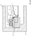
- FIG. 9D shown cutting process step is in the Figure 9E shown enlarged.
- the first jaw 13 is shaped so that it presses both the upper film 7 in the region of the Aufr employedecke A, B, C against the second jaw 18 and the upper film 7 partially against the edge region R of the packaging shell V.
- the upper film 7 is optimally fixed for cutting the Aufr concernedecke A, B, C.
- Figure 9E in that in a region X the first clamping jaw 13 presses the upper film 7 against the second clamping jaw 18 arranged underneath and in a region Y the upper film 7 presses on a part of the edge region R of the tray receptacle V positioned underneath.
- the cutting of the top film 7, including the Aufr employedecke A, B, C, takes place before the sealing process.
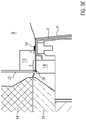
- FIG. 9F shows schematically the sealing process.
- the sealing seam S is produced circumferentially around the edge region R of the packaging shell V by means of timed pressure and temperature input.
- the inventive concept can be except for the production of Vakuumskinpackungen F also excellent for the production of other types of packaging use.
- the sealing station according to the invention can be used to produce packages with tear-open and without atmosphere exchange, packaging with tear-open and a gas-permeable lid film, and packaging with protective atmosphere generated therein.
Landscapes
- Engineering & Computer Science (AREA)
- Mechanical Engineering (AREA)
- Life Sciences & Earth Sciences (AREA)
- Forests & Forestry (AREA)
- Chemical & Material Sciences (AREA)
- Dispersion Chemistry (AREA)
- Closing Of Containers (AREA)
- Vacuum Packaging (AREA)
Priority Applications (4)
| Application Number | Priority Date | Filing Date | Title |
|---|---|---|---|
| ES17188571T ES2824455T3 (es) | 2017-08-30 | 2017-08-30 | Estación de sellado así como procedimiento para la producción de embalajes de película con esquina de apertura |
| EP17188571.8A EP3450327B1 (fr) | 2017-08-30 | 2017-08-30 | Station de soudage ainsi que procédé de fabrication d'emballage blister pourvu d'un angle d'arrachage |
| US16/115,664 US11292653B2 (en) | 2017-08-30 | 2018-08-29 | Sealing station and method for producing skin packaging with tear-off corner |
| CN201811002126.7A CN109421967B (zh) | 2017-08-30 | 2018-08-30 | 密封站及用于制造具有撕开角的贴体包装的方法 |
Applications Claiming Priority (1)
| Application Number | Priority Date | Filing Date | Title |
|---|---|---|---|
| EP17188571.8A EP3450327B1 (fr) | 2017-08-30 | 2017-08-30 | Station de soudage ainsi que procédé de fabrication d'emballage blister pourvu d'un angle d'arrachage |
Publications (2)
| Publication Number | Publication Date |
|---|---|
| EP3450327A1 true EP3450327A1 (fr) | 2019-03-06 |
| EP3450327B1 EP3450327B1 (fr) | 2020-07-29 |
Family
ID=59829165
Family Applications (1)
| Application Number | Title | Priority Date | Filing Date |
|---|---|---|---|
| EP17188571.8A Active EP3450327B1 (fr) | 2017-08-30 | 2017-08-30 | Station de soudage ainsi que procédé de fabrication d'emballage blister pourvu d'un angle d'arrachage |
Country Status (4)
| Country | Link |
|---|---|
| US (1) | US11292653B2 (fr) |
| EP (1) | EP3450327B1 (fr) |
| CN (1) | CN109421967B (fr) |
| ES (1) | ES2824455T3 (fr) |
Cited By (2)
| Publication number | Priority date | Publication date | Assignee | Title |
|---|---|---|---|---|
| EP3581516B1 (fr) * | 2018-06-11 | 2022-02-23 | MULTIVAC Sepp Haggenmüller SE & Co. KG | Emballage blister ainsi que procédé et station de scellement destinés à fabriquer un emballage blister |
| DE102020129551A1 (de) | 2020-11-10 | 2022-05-12 | Multivac Sepp Haggenmüller Se & Co. Kg | Formstation zum Ausformen von Verpackungsmulden |
Families Citing this family (6)
| Publication number | Priority date | Publication date | Assignee | Title |
|---|---|---|---|---|
| US20180022490A1 (en) * | 2016-07-21 | 2018-01-25 | Ross Industries, Inc. | Vacuum sealing system, apparatus, and method |
| DE102019206280A1 (de) * | 2019-05-02 | 2020-11-05 | Multivac Sepp Haggenmüller Se & Co. Kg | Siegelwerkzeug und Verfahren zum Versiegeln von Schalen |
| MX2023005419A (es) * | 2020-11-09 | 2023-05-22 | Sonoco Dev Inc | Montaje de sellado y corte para maquina de sellado en caliente. |
| EP4001136A1 (fr) * | 2020-11-20 | 2022-05-25 | ULMA Packaging Technological Centre, S. COOP | Machine d'emballage à atmosphère modifiée |
| EP4032689A1 (fr) | 2021-01-22 | 2022-07-27 | Ulma Packaging, S.Coop. | Thermoscelleuse pour générer des emballages faciles à ouvrir |
| IT202300014391A1 (it) * | 2023-07-10 | 2025-01-10 | G Mondini S P A | Apparecchiatura e metodo per l’applicazione di un coperchio ad un supporto contenente un prodotto e relativa confezione |
Citations (6)
| Publication number | Priority date | Publication date | Assignee | Title |
|---|---|---|---|---|
| US20040206048A1 (en) * | 2003-04-17 | 2004-10-21 | Shikoku Kakoki Co., Ltd. | Apparatus for sealing containers |
| EP1747995A1 (fr) | 2005-07-26 | 2007-01-31 | Jörg von Seggern GmbH | Procédé et appareil pour emballer des articles dans un film à pelliplacage, étanche au gaz |
| US20110072764A1 (en) * | 2009-09-30 | 2011-03-31 | Ross Industries, Inc. | Method and apparatus for sealing containers |
| EP2441683B1 (fr) | 2010-10-12 | 2012-12-12 | MULTIVAC Sepp Haggenmüller GmbH & Co KG | Station de verrouillage et procédé de coupe d'une pellicule de couvercle |
| WO2015121270A1 (fr) * | 2014-02-12 | 2015-08-20 | Cryovac, Inc. | Emballage pour un produit et appareil et procédé pour emballer un produit |
| WO2016193006A1 (fr) * | 2015-05-29 | 2016-12-08 | Cryovac, Inc. | Appareil et procédé d'emballage d'un produit |
Family Cites Families (26)
| Publication number | Priority date | Publication date | Assignee | Title |
|---|---|---|---|---|
| CH610261A5 (fr) * | 1977-03-11 | 1979-04-12 | Sig Schweiz Industrieges | |
| US4685274A (en) * | 1983-07-12 | 1987-08-11 | Garwood Ltd. | Packaging foodstuffs |
| JP2522449B2 (ja) * | 1990-07-27 | 1996-08-07 | 日本精機株式会社 | 包装装置 |
| DE19541541A1 (de) * | 1995-11-08 | 1997-05-15 | Focke & Co | Verpackung für insbesondere Zigaretten sowie Verfahren und Vorrichtung zum Herstellen derselben |
| EA200200139A1 (ru) * | 1999-07-27 | 2002-08-29 | Санфорд Редмонд Инк. | Компактная машина для формования, заполнения и герметичного закрытия упаковок |
| US20040194432A1 (en) * | 2001-07-13 | 2004-10-07 | Muller Otto Carl | Tamper-evident container, a blank for the container, a method of packing a product, a method of securing at least one product to a container, and a packing machine for skin packing a product |
| US6834476B2 (en) * | 2002-10-17 | 2004-12-28 | Ibaraki Seiki Machinery Company, Ltd. | Sealing and packaging device for cover film on tray |
| JP4675665B2 (ja) * | 2005-04-11 | 2011-04-27 | 株式会社イシダ | 包装機 |
| DE102008035994A1 (de) * | 2008-08-01 | 2010-02-11 | Multivac Sepp Haggenmüller Gmbh & Co. Kg | Verpackungsmaschine mit einer Ultraschallvorrichtung |
| CN101357694B (zh) * | 2008-09-19 | 2010-09-29 | 江南大学 | 全自动连续盒式气调包装机 |
| DE102009020892A1 (de) * | 2009-05-13 | 2011-02-10 | Multivac Sepp Haggenmüller Gmbh & Co. Kg | Verpackungsmaschine und Verfahren zum Verschließen von Behältern mit Deckeln |
| CN201545205U (zh) * | 2009-10-18 | 2010-08-11 | 苏州达信科技电子有限公司 | 包装装置 |
| DE102010004635B4 (de) * | 2010-01-14 | 2011-09-22 | Multivac Sepp Haggenmüller Gmbh & Co. Kg | Siegelwerkzeug |
| IT1399314B1 (it) * | 2010-04-08 | 2013-04-16 | Gruppo Fabbri S P A | Apparato a campane contrapposte, per il confezionamento in atmosfera modificata di prodotti posti in vassoi. |
| CN201961582U (zh) * | 2010-12-22 | 2011-09-07 | 浙江佑天元包装机械制造有限公司 | 热成型包装机的裁切机构 |
| DE102010055967B4 (de) * | 2010-12-23 | 2015-07-16 | Multivac Sepp Haggenmüller Gmbh & Co. Kg | Arbeitsstation mit einem Schneidwerkzeug zum schnellen Schneiden einer Folienbahn |
| DE102011105513A1 (de) * | 2011-06-24 | 2012-12-27 | Multivac Sepp Haggenmüller Gmbh & Co. Kg | Verfahren und Siegelstation zum Versiegeln von Verpackungen |
| ITBO20110403A1 (it) * | 2011-07-07 | 2013-01-08 | Gruppo Fabbri Vignola Spa | Apparato a campane contrapposte per il confezionamento in atmosfera modificata di prodotti posti in vassoi. |
| DE102011108228B4 (de) * | 2011-07-21 | 2013-01-31 | Multivac Sepp Haggenmüller Gmbh & Co. Kg | Schalenverschließmaschine mit Aufwickelvorrichtung |
| US8871424B2 (en) * | 2012-01-20 | 2014-10-28 | Cryovac, Inc. | Laser imageable polyolefin film |
| DE102012005891A1 (de) * | 2012-03-23 | 2013-09-26 | Multivac Sepp Haggenmüller Gmbh & Co. Kg | Verpackungsmaschine mit Siegelstation zum Begasen einer Verpackung |
| DE102012006696A1 (de) * | 2012-03-30 | 2013-10-02 | Multivac Sepp Haggenmüller Gmbh & Co. Kg | Verpackungsmaschine mit einer Siegelvorrichtung |
| ITBO20120549A1 (it) * | 2012-10-09 | 2014-04-10 | Gruppo Fabbri Vignola Spa | Apparato a campane contrapposte, per il confezionamento in atmosfera modificata di prodotti posti in vassoi |
| US20140116002A1 (en) * | 2012-10-26 | 2014-05-01 | Illinois Tool Works Inc. | Protective body, heat sealing system that includes the protective body, and method for providing the protective body |
| ES2609057T3 (es) * | 2014-02-11 | 2017-04-18 | Cryovac, Inc. | Aparato y procedimiento para envasar un producto |
| US20170305586A1 (en) * | 2014-10-10 | 2017-10-26 | Cryovac, Inc. | Apparatus and process for packaging a product |
-
2017
- 2017-08-30 EP EP17188571.8A patent/EP3450327B1/fr active Active
- 2017-08-30 ES ES17188571T patent/ES2824455T3/es active Active
-
2018
- 2018-08-29 US US16/115,664 patent/US11292653B2/en active Active
- 2018-08-30 CN CN201811002126.7A patent/CN109421967B/zh active Active
Patent Citations (6)
| Publication number | Priority date | Publication date | Assignee | Title |
|---|---|---|---|---|
| US20040206048A1 (en) * | 2003-04-17 | 2004-10-21 | Shikoku Kakoki Co., Ltd. | Apparatus for sealing containers |
| EP1747995A1 (fr) | 2005-07-26 | 2007-01-31 | Jörg von Seggern GmbH | Procédé et appareil pour emballer des articles dans un film à pelliplacage, étanche au gaz |
| US20110072764A1 (en) * | 2009-09-30 | 2011-03-31 | Ross Industries, Inc. | Method and apparatus for sealing containers |
| EP2441683B1 (fr) | 2010-10-12 | 2012-12-12 | MULTIVAC Sepp Haggenmüller GmbH & Co KG | Station de verrouillage et procédé de coupe d'une pellicule de couvercle |
| WO2015121270A1 (fr) * | 2014-02-12 | 2015-08-20 | Cryovac, Inc. | Emballage pour un produit et appareil et procédé pour emballer un produit |
| WO2016193006A1 (fr) * | 2015-05-29 | 2016-12-08 | Cryovac, Inc. | Appareil et procédé d'emballage d'un produit |
Cited By (2)
| Publication number | Priority date | Publication date | Assignee | Title |
|---|---|---|---|---|
| EP3581516B1 (fr) * | 2018-06-11 | 2022-02-23 | MULTIVAC Sepp Haggenmüller SE & Co. KG | Emballage blister ainsi que procédé et station de scellement destinés à fabriquer un emballage blister |
| DE102020129551A1 (de) | 2020-11-10 | 2022-05-12 | Multivac Sepp Haggenmüller Se & Co. Kg | Formstation zum Ausformen von Verpackungsmulden |
Also Published As
| Publication number | Publication date |
|---|---|
| US20190062032A1 (en) | 2019-02-28 |
| CN109421967B (zh) | 2020-10-27 |
| ES2824455T3 (es) | 2021-05-12 |
| EP3450327B1 (fr) | 2020-07-29 |
| US11292653B2 (en) | 2022-04-05 |
| CN109421967A (zh) | 2019-03-05 |
Similar Documents
| Publication | Publication Date | Title |
|---|---|---|
| EP3450327B1 (fr) | Station de soudage ainsi que procédé de fabrication d'emballage blister pourvu d'un angle d'arrachage | |
| EP1521706B1 (fr) | Procede et machine d'emballage pour emballer un produit situe dans une barquette | |
| EP1935789B1 (fr) | Procédé et installation pour emballer des objets d'une façon étanche au gaz | |
| EP1747995B1 (fr) | Procédé et appareil pour emballer des articles dans un film à pelliplacage, étanche au gaz | |
| EP2769923B1 (fr) | Machine d'emballage par emboutissage profond avec poste de scellage et procédé | |
| DE2327286C2 (de) | Verpackungsvorrichtung | |
| DE2122110A1 (de) | Verfahren und Anordnung zur Herstellung einer Skinverpackung | |
| DE102012018974B4 (de) | Tiefziehverpackungsmaschine mit Stempelformung | |
| EP3581516A1 (fr) | Emballage blister ainsi que procédé et station de scellement destinés à fabriquer un emballage blister | |
| EP2800699B1 (fr) | Machine d'emballage avec poste de découpe | |
| EP3405399A2 (fr) | Outil de scellage pour un emballage pelliplaqué | |
| EP2684803B1 (fr) | Procédé de fabrication d'un emballage | |
| EP4168313A1 (fr) | Machine d'emballage comprenant un outil de découpage | |
| EP3446989B1 (fr) | Machine d'emballage destinée à la fabrication d'un emballage multicouche | |
| WO2017009179A1 (fr) | Machine d'emballage à évacuation de rognures | |
| WO2007090571A2 (fr) | Poste de scellage d'une machine d'emballage | |
| EP4155056A1 (fr) | Station de formage pour une machine à emboutir et à envelopper sous pellicule, machine à emboutir et à envelopper sous pellicule, son utilisation et procédé d'emboutissage sous un film en matière plastique | |
| DE102008057609B4 (de) | Siegelstation für eine Verpackungsmaschine und Verfahren zum Betreiben derselben | |
| DE102005055197B3 (de) | Verfahren und Vorrichtung zum Herstellen einer Verpackung | |
| EP1785258A1 (fr) | Procédé et dispositif pour fabriquer un corps creux avec au moins une pièce d'insertion | |
| DE102024115218A1 (de) | Verfahren und Vorrichtung zum Aufbringen einer Deckelfolie auf eine Verpackungsschale | |
| DE102004055007B4 (de) | Verfahren und Vorrichtung zum Verpacken von Stückgut | |
| DE102008039158A1 (de) | Vorrichtung zum Siegeln von Packungen | |
| EP4667208A2 (fr) | Procédé et station de revêtement d'une barquette d'emballage | |
| EP4617031A1 (fr) | Moule et procédé de laminage de pièces moulées tridimensionnelles à partir d'un matériau fibreux |
Legal Events
| Date | Code | Title | Description |
|---|---|---|---|
| PUAI | Public reference made under article 153(3) epc to a published international application that has entered the european phase |
Free format text: ORIGINAL CODE: 0009012 |
|
| STAA | Information on the status of an ep patent application or granted ep patent |
Free format text: STATUS: THE APPLICATION HAS BEEN PUBLISHED |
|
| AK | Designated contracting states |
Kind code of ref document: A1 Designated state(s): AL AT BE BG CH CY CZ DE DK EE ES FI FR GB GR HR HU IE IS IT LI LT LU LV MC MK MT NL NO PL PT RO RS SE SI SK SM TR |
|
| AX | Request for extension of the european patent |
Extension state: BA ME |
|
| STAA | Information on the status of an ep patent application or granted ep patent |
Free format text: STATUS: REQUEST FOR EXAMINATION WAS MADE |
|
| 17P | Request for examination filed |
Effective date: 20190906 |
|
| RBV | Designated contracting states (corrected) |
Designated state(s): AL AT BE BG CH CY CZ DE DK EE ES FI FR GB GR HR HU IE IS IT LI LT LU LV MC MK MT NL NO PL PT RO RS SE SI SK SM TR |
|
| GRAP | Despatch of communication of intention to grant a patent |
Free format text: ORIGINAL CODE: EPIDOSNIGR1 |
|
| STAA | Information on the status of an ep patent application or granted ep patent |
Free format text: STATUS: GRANT OF PATENT IS INTENDED |
|
| RIC1 | Information provided on ipc code assigned before grant |
Ipc: B26D 7/26 20060101ALI20200131BHEP Ipc: B29C 65/74 20060101ALI20200131BHEP Ipc: B29C 65/00 20060101ALI20200131BHEP Ipc: B29L 31/00 20060101ALI20200131BHEP Ipc: B65B 61/06 20060101ALI20200131BHEP Ipc: B65B 7/16 20060101AFI20200131BHEP Ipc: B65B 61/18 20060101ALI20200131BHEP Ipc: B29C 65/02 20060101ALI20200131BHEP Ipc: B29C 65/18 20060101ALI20200131BHEP |
|
| INTG | Intention to grant announced |
Effective date: 20200303 |
|
| GRAS | Grant fee paid |
Free format text: ORIGINAL CODE: EPIDOSNIGR3 |
|
| GRAA | (expected) grant |
Free format text: ORIGINAL CODE: 0009210 |
|
| STAA | Information on the status of an ep patent application or granted ep patent |
Free format text: STATUS: THE PATENT HAS BEEN GRANTED |
|
| AK | Designated contracting states |
Kind code of ref document: B1 Designated state(s): AL AT BE BG CH CY CZ DE DK EE ES FI FR GB GR HR HU IE IS IT LI LT LU LV MC MK MT NL NO PL PT RO RS SE SI SK SM TR |
|
| REG | Reference to a national code |
Ref country code: CH Ref legal event code: NV Representative=s name: BOVARD AG PATENT- UND MARKENANWAELTE, CH Ref country code: CH Ref legal event code: EP |
|
| REG | Reference to a national code |
Ref country code: AT Ref legal event code: REF Ref document number: 1295505 Country of ref document: AT Kind code of ref document: T Effective date: 20200815 |
|
| REG | Reference to a national code |
Ref country code: IE Ref legal event code: FG4D Free format text: LANGUAGE OF EP DOCUMENT: GERMAN |
|
| REG | Reference to a national code |
Ref country code: DE Ref legal event code: R096 Ref document number: 502017006398 Country of ref document: DE |
|
| REG | Reference to a national code |
Ref country code: NL Ref legal event code: FP |
|
| REG | Reference to a national code |
Ref country code: LT Ref legal event code: MG4D |
|
| PG25 | Lapsed in a contracting state [announced via postgrant information from national office to epo] |
Ref country code: BG Free format text: LAPSE BECAUSE OF FAILURE TO SUBMIT A TRANSLATION OF THE DESCRIPTION OR TO PAY THE FEE WITHIN THE PRESCRIBED TIME-LIMIT Effective date: 20201029 Ref country code: NO Free format text: LAPSE BECAUSE OF FAILURE TO SUBMIT A TRANSLATION OF THE DESCRIPTION OR TO PAY THE FEE WITHIN THE PRESCRIBED TIME-LIMIT Effective date: 20201029 Ref country code: HR Free format text: LAPSE BECAUSE OF FAILURE TO SUBMIT A TRANSLATION OF THE DESCRIPTION OR TO PAY THE FEE WITHIN THE PRESCRIBED TIME-LIMIT Effective date: 20200729 Ref country code: SE Free format text: LAPSE BECAUSE OF FAILURE TO SUBMIT A TRANSLATION OF THE DESCRIPTION OR TO PAY THE FEE WITHIN THE PRESCRIBED TIME-LIMIT Effective date: 20200729 Ref country code: PT Free format text: LAPSE BECAUSE OF FAILURE TO SUBMIT A TRANSLATION OF THE DESCRIPTION OR TO PAY THE FEE WITHIN THE PRESCRIBED TIME-LIMIT Effective date: 20201130 Ref country code: FI Free format text: LAPSE BECAUSE OF FAILURE TO SUBMIT A TRANSLATION OF THE DESCRIPTION OR TO PAY THE FEE WITHIN THE PRESCRIBED TIME-LIMIT Effective date: 20200729 Ref country code: LT Free format text: LAPSE BECAUSE OF FAILURE TO SUBMIT A TRANSLATION OF THE DESCRIPTION OR TO PAY THE FEE WITHIN THE PRESCRIBED TIME-LIMIT Effective date: 20200729 Ref country code: GR Free format text: LAPSE BECAUSE OF FAILURE TO SUBMIT A TRANSLATION OF THE DESCRIPTION OR TO PAY THE FEE WITHIN THE PRESCRIBED TIME-LIMIT Effective date: 20201030 |
|
| PG25 | Lapsed in a contracting state [announced via postgrant information from national office to epo] |
Ref country code: IS Free format text: LAPSE BECAUSE OF FAILURE TO SUBMIT A TRANSLATION OF THE DESCRIPTION OR TO PAY THE FEE WITHIN THE PRESCRIBED TIME-LIMIT Effective date: 20201129 Ref country code: LV Free format text: LAPSE BECAUSE OF FAILURE TO SUBMIT A TRANSLATION OF THE DESCRIPTION OR TO PAY THE FEE WITHIN THE PRESCRIBED TIME-LIMIT Effective date: 20200729 Ref country code: PL Free format text: LAPSE BECAUSE OF FAILURE TO SUBMIT A TRANSLATION OF THE DESCRIPTION OR TO PAY THE FEE WITHIN THE PRESCRIBED TIME-LIMIT Effective date: 20200729 Ref country code: RS Free format text: LAPSE BECAUSE OF FAILURE TO SUBMIT A TRANSLATION OF THE DESCRIPTION OR TO PAY THE FEE WITHIN THE PRESCRIBED TIME-LIMIT Effective date: 20200729 |
|
| PG25 | Lapsed in a contracting state [announced via postgrant information from national office to epo] |
Ref country code: LU Free format text: LAPSE BECAUSE OF NON-PAYMENT OF DUE FEES Effective date: 20200830 Ref country code: CZ Free format text: LAPSE BECAUSE OF FAILURE TO SUBMIT A TRANSLATION OF THE DESCRIPTION OR TO PAY THE FEE WITHIN THE PRESCRIBED TIME-LIMIT Effective date: 20200729 Ref country code: DK Free format text: LAPSE BECAUSE OF FAILURE TO SUBMIT A TRANSLATION OF THE DESCRIPTION OR TO PAY THE FEE WITHIN THE PRESCRIBED TIME-LIMIT Effective date: 20200729 Ref country code: RO Free format text: LAPSE BECAUSE OF FAILURE TO SUBMIT A TRANSLATION OF THE DESCRIPTION OR TO PAY THE FEE WITHIN THE PRESCRIBED TIME-LIMIT Effective date: 20200729 Ref country code: SM Free format text: LAPSE BECAUSE OF FAILURE TO SUBMIT A TRANSLATION OF THE DESCRIPTION OR TO PAY THE FEE WITHIN THE PRESCRIBED TIME-LIMIT Effective date: 20200729 Ref country code: EE Free format text: LAPSE BECAUSE OF FAILURE TO SUBMIT A TRANSLATION OF THE DESCRIPTION OR TO PAY THE FEE WITHIN THE PRESCRIBED TIME-LIMIT Effective date: 20200729 |
|
| REG | Reference to a national code |
Ref country code: DE Ref legal event code: R097 Ref document number: 502017006398 Country of ref document: DE |
|
| REG | Reference to a national code |
Ref country code: ES Ref legal event code: FG2A Ref document number: 2824455 Country of ref document: ES Kind code of ref document: T3 Effective date: 20210512 |
|
| REG | Reference to a national code |
Ref country code: BE Ref legal event code: MM Effective date: 20200831 |
|
| PG25 | Lapsed in a contracting state [announced via postgrant information from national office to epo] |
Ref country code: AL Free format text: LAPSE BECAUSE OF FAILURE TO SUBMIT A TRANSLATION OF THE DESCRIPTION OR TO PAY THE FEE WITHIN THE PRESCRIBED TIME-LIMIT Effective date: 20200729 |
|
| PLBE | No opposition filed within time limit |
Free format text: ORIGINAL CODE: 0009261 |
|
| STAA | Information on the status of an ep patent application or granted ep patent |
Free format text: STATUS: NO OPPOSITION FILED WITHIN TIME LIMIT |
|
| PG25 | Lapsed in a contracting state [announced via postgrant information from national office to epo] |
Ref country code: SK Free format text: LAPSE BECAUSE OF FAILURE TO SUBMIT A TRANSLATION OF THE DESCRIPTION OR TO PAY THE FEE WITHIN THE PRESCRIBED TIME-LIMIT Effective date: 20200729 |
|
| 26N | No opposition filed |
Effective date: 20210430 |
|
| PG25 | Lapsed in a contracting state [announced via postgrant information from national office to epo] |
Ref country code: IE Free format text: LAPSE BECAUSE OF NON-PAYMENT OF DUE FEES Effective date: 20200830 Ref country code: SI Free format text: LAPSE BECAUSE OF FAILURE TO SUBMIT A TRANSLATION OF THE DESCRIPTION OR TO PAY THE FEE WITHIN THE PRESCRIBED TIME-LIMIT Effective date: 20200729 Ref country code: BE Free format text: LAPSE BECAUSE OF NON-PAYMENT OF DUE FEES Effective date: 20200831 |
|
| PG25 | Lapsed in a contracting state [announced via postgrant information from national office to epo] |
Ref country code: TR Free format text: LAPSE BECAUSE OF FAILURE TO SUBMIT A TRANSLATION OF THE DESCRIPTION OR TO PAY THE FEE WITHIN THE PRESCRIBED TIME-LIMIT Effective date: 20200729 Ref country code: MT Free format text: LAPSE BECAUSE OF FAILURE TO SUBMIT A TRANSLATION OF THE DESCRIPTION OR TO PAY THE FEE WITHIN THE PRESCRIBED TIME-LIMIT Effective date: 20200729 Ref country code: CY Free format text: LAPSE BECAUSE OF FAILURE TO SUBMIT A TRANSLATION OF THE DESCRIPTION OR TO PAY THE FEE WITHIN THE PRESCRIBED TIME-LIMIT Effective date: 20200729 |
|
| PG25 | Lapsed in a contracting state [announced via postgrant information from national office to epo] |
Ref country code: MK Free format text: LAPSE BECAUSE OF FAILURE TO SUBMIT A TRANSLATION OF THE DESCRIPTION OR TO PAY THE FEE WITHIN THE PRESCRIBED TIME-LIMIT Effective date: 20200729 Ref country code: MC Free format text: LAPSE BECAUSE OF FAILURE TO SUBMIT A TRANSLATION OF THE DESCRIPTION OR TO PAY THE FEE WITHIN THE PRESCRIBED TIME-LIMIT Effective date: 20200729 |
|
| P01 | Opt-out of the competence of the unified patent court (upc) registered |
Effective date: 20230801 |
|
| PGFP | Annual fee paid to national office [announced via postgrant information from national office to epo] |
Ref country code: NL Payment date: 20250821 Year of fee payment: 9 |
|
| PGFP | Annual fee paid to national office [announced via postgrant information from national office to epo] |
Ref country code: ES Payment date: 20250917 Year of fee payment: 9 |
|
| PGFP | Annual fee paid to national office [announced via postgrant information from national office to epo] |
Ref country code: DE Payment date: 20250819 Year of fee payment: 9 |
|
| PGFP | Annual fee paid to national office [announced via postgrant information from national office to epo] |
Ref country code: IT Payment date: 20250829 Year of fee payment: 9 |
|
| PGFP | Annual fee paid to national office [announced via postgrant information from national office to epo] |
Ref country code: GB Payment date: 20250822 Year of fee payment: 9 |
|
| PGFP | Annual fee paid to national office [announced via postgrant information from national office to epo] |
Ref country code: FR Payment date: 20250827 Year of fee payment: 9 Ref country code: AT Payment date: 20250819 Year of fee payment: 9 |
|
| PGFP | Annual fee paid to national office [announced via postgrant information from national office to epo] |
Ref country code: CH Payment date: 20250901 Year of fee payment: 9 |