EP3450357A1 - Wurfvorrichtung zum auswerfen von hackgut - Google Patents
Wurfvorrichtung zum auswerfen von hackgut Download PDFInfo
- Publication number
- EP3450357A1 EP3450357A1 EP18178694.8A EP18178694A EP3450357A1 EP 3450357 A1 EP3450357 A1 EP 3450357A1 EP 18178694 A EP18178694 A EP 18178694A EP 3450357 A1 EP3450357 A1 EP 3450357A1
- Authority
- EP
- European Patent Office
- Prior art keywords
- throwing
- rotation
- end piece
- wood chips
- blade
- Prior art date
- Legal status (The legal status is an assumption and is not a legal conclusion. Google has not performed a legal analysis and makes no representation as to the accuracy of the status listed.)
- Granted
Links
Images


Classifications
-
- B—PERFORMING OPERATIONS; TRANSPORTING
- B65—CONVEYING; PACKING; STORING; HANDLING THIN OR FILAMENTARY MATERIAL
- B65G—TRANSPORT OR STORAGE DEVICES, e.g. CONVEYORS FOR LOADING OR TIPPING, SHOP CONVEYOR SYSTEMS OR PNEUMATIC TUBE CONVEYORS
- B65G29/00—Rotary conveyors, e.g. rotating discs, arms, star-wheels or cones
-
- B—PERFORMING OPERATIONS; TRANSPORTING
- B65—CONVEYING; PACKING; STORING; HANDLING THIN OR FILAMENTARY MATERIAL
- B65G—TRANSPORT OR STORAGE DEVICES, e.g. CONVEYORS FOR LOADING OR TIPPING, SHOP CONVEYOR SYSTEMS OR PNEUMATIC TUBE CONVEYORS
- B65G69/00—Auxiliary measures taken, or devices used, in connection with loading or unloading
- B65G69/04—Spreading out the materials conveyed over the whole surface to be loaded; Trimming heaps of loose materials
- B65G69/0458—Spreading out the materials conveyed over the whole surface to be loaded; Trimming heaps of loose materials with rotating means, e.g. tables, arms
-
- B—PERFORMING OPERATIONS; TRANSPORTING
- B65—CONVEYING; PACKING; STORING; HANDLING THIN OR FILAMENTARY MATERIAL
- B65G—TRANSPORT OR STORAGE DEVICES, e.g. CONVEYORS FOR LOADING OR TIPPING, SHOP CONVEYOR SYSTEMS OR PNEUMATIC TUBE CONVEYORS
- B65G31/00—Mechanical throwing machines for articles or solid materials
- B65G31/04—Mechanical throwing machines for articles or solid materials comprising discs, drums, or like rotary impellers
-
- F—MECHANICAL ENGINEERING; LIGHTING; HEATING; WEAPONS; BLASTING
- F23—COMBUSTION APPARATUS; COMBUSTION PROCESSES
- F23K—FEEDING FUEL TO COMBUSTION APPARATUS
- F23K2203/00—Feeding arrangements
- F23K2203/20—Feeding/conveying devices
Definitions
- the invention relates to a throwing device for ejecting wood chips, comprising a throwing wheel which can be displaced by a drive means in rotation about a rotation axis and having vanes, wherein the throwing wheel is surrounded by a casing drum having an inlet opening provided for feeding the wood chips and an outlet opening for ejecting the woodchip
- the throwing blades of the throwing wheel which is set in rotation, grasp the wood chips supplied via the inlet opening and eject them through the outlet opening.
- the wood chips which was usually produced by appropriate wood chippers in standard sizes, is fed to a throwing device, the wood chips with the help of the throwing wheel and the casting blades arranged thereon is ejected to a nearest means of transport.
- the standard size of the wood chips should be maintained.
- the smallest possible distance is provided, which allows the throwing wheel or the throwing vanes to perform a rotational movement without rubbing against the housing drum and to minimize losses in the delivery rate.
- the crushing or grinding described above also produces fine dust from wood, which is ejected through the throwing device as well with the other wood chips and reduces the heating power in a later application as a fuel.
- At least one throwing wing has at least one end piece which is separate from the respective blade surface and which can be pivoted and its orientation or position can be changed from a folded state to a completely unfolded state, the end piece being folded in the folded state each blade surface in the radial extent at least partially protrudes.
- the at least one end piece is formed in the form of a plate.
- the at least one end piece is made of metal or of a material which corresponds approximately to the density of a metal.
- the end piece is made of a material having such a weight that the end piece aligns in a radial movement of the throwing wheel in the radial direction to the axis of rotation, wherein the force acting through a plate-like shape of the tail and by the rotation air resistance is negligible, negligible at least in such a way that the acting air resistance does not counteract an orientation of the end piece radially to the axis of rotation.
- At the radially outer end of the at least one end piece - seen in a folded state of the tail - projections may be arranged. These cause noise generated by the rotation to be reduced.
- the at least one end piece can yield in the direction of the unfolded state in the event of the action of a load by the action of wood chips against the direction of rotation of the throwing wheel.
- the at least one end piece yields only when the force generated by wood chips exceeds the force which holds or aligns the at least one end piece in the position of the folded state and so counteracts that the at least one end piece in the direction the unfolded state or the fully deployed state recedes.
- the at least one end piece has at least one adjusting means, wherein the at least one end piece is already in the folded-in state in the non-operational state of the device due to the actuating means.
- the at least one actuating means can give way to a force generated by wood chips against the direction of rotation of the throwing wheel and escapes the at least one end piece in the direction of the unfolded state.
- the adjusting means is in the form of one or more screws, wherein the at least one end piece is screwed to the corresponding blade surface of the at least one throwing wing.
- the adjusting element is designed in the form of one or more elastic spring elements.
- the at least one throwing blade has a stop which limits a movement of the end piece against the direction of rotation of the throwing wheel.
- This stop essentially determines the position of the fully unfolded state of the at least one end piece.
- the at least one end piece in its fully unfolded state does not project an imaginary circular line described by the rotational movement of the radially outermost point of the respective throwing wing about the axis of rotation.
- the distance of the radially outermost end of the spreader blades to the housing drum substantially corresponds to the standard size of the respective wood chips, wherein the distance may vary depending on the corresponding standard size of the wood chips.
- the probability of blocking the throwing wings or the throwing wheel by wood chips can be minimized by a multiple.
- each throwing wings has at least one end piece.
- each throwing wings has at least two or more end pieces.
- the throwing device may further comprise a protective disk, which is arranged on the side facing away from the inlet opening of the throwing wheel.
- the protective disk can be connected in a rotationally fixed manner to the throwing wheel.
- the throwing wheel or the throwing wings are welded to the protective pane.
- the radius of the protective pane corresponds at least to the radial extent of a throwing wing.
- the protective pane has at least one opening which is arranged in the area between casting vanes adjacent in the circumferential direction of the protective pane.
- the protective pane has an opening in the region between casting vanes adjacent in the circumferential direction of the protective pane.
- the protective pane also has a corresponding cover for each opening, which can be fastened to the protective pane with a fastening means.
- Such openings can serve as maintenance openings, so that not the entire throwing wheel must be removed. For this purpose, only the corresponding cover is removed.
- the cover has a smaller thickness than the protective pane.
- the total weight of the protective pane can be reduced while the functionality of the protective pane provided remains the same.
- the throwing vanes can be arranged radially or in a star shape about the axis of rotation.
- blade surfaces are positioned orthogonal to the direction of rotation.
- the blade surfaces may have a taper in their planar extension in the direction of the axis of rotation.
- At least one spreader blade has at least one limiting projection projecting in the direction of rotation.
- At least one spreader blade has on its side facing away from the protective disk a limiting projection projecting in the direction of rotation, which substantially follows the edge profile of the blade surface.
- At least one blade surface has a guide projection projecting in the direction of rotation, which is aligned on the blade surface at an angle to the side facing away from the inlet opening.
- Such a guide projection conveys the wood chips, during the rotational movement of the throwing wheel and the resulting centrifugal force further in the direction of the inlet opening facing away from the throwing blade, whereby a more uniform and targeted throwing beam is generated during ejection of the wood chips.
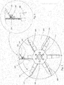
- Fig. 1 shows a side view of an exemplary casting device 50 for the extraction of wood chips, comprising a by a driving means which is not shown in the figures, about a rotation axis X displaceable throwing wheel 100 having in rotation with blade surfaces 210 throwing vanes 200, with the throwing wheel 100 of a housing drum 300 surrounded, which has a provided for supplying the wood chips inlet opening 310 and an outlet opening 320 for ejecting the wood chips.
- a drive means for example, a V-belt drive, hydraulic drive or a gear drive, in particular a planetary gear can be provided.
- the spreader blades 200 are arranged radially or in a star shape about the rotation axis X on the throwing wheel 100 , wherein each spreader blade 200 has a blade surface 210 arranged substantially orthogonally to the direction of rotation. From the in Fig. 1 shown Wurferieln 200 have three Wurferiel 200 in a direction of rotation protruding limiting projection 220 . In a further embodiment, however, it can also be provided that all or at least one throwing wing 200 has a limiting projection 220 .
- the limiting projections 220 ensure that the wood chips are better grasped by the respective blade surface 210 during feeding through the inlet opening 310 and more chips per casting wing 200 can be ejected.
- the wood chips are less regrind, since less friction between the respective blade surface 210 and the housing drum 300 is formed.
- the spreader vanes 200 at its radially outer end portion a pivotally mounted end piece 230 which is adapted to align in the operation of the throwing device 50 due to the centrifugal force generated by the rotational movement of the throwing wheel 100 in the radial direction to the axis of rotation X of the throwing wheel 100 and the respective Spreader wings 200 in radial extent to survive, and also give in one of the orientation in the radial direction to the axis of rotation X counteracting force by wood chips against the direction of rotation of the throwing wheel 100 .
- this force In order for the respective end piece 230 to yield when force is applied, this force must be so high that it at least hampers the alignment of the end piece 230 in the radial direction to the axis of rotation X by the centrifugal force.
- the end pieces 230 in Fig. 1 are in an unfolded state and parallel to the blade surface 210 of the respective throwing blade 200th
- Fig. 2 is a cross section through the section III-III Fig. 1 shows, the blade surfaces 210 in their planar expansion in Direction of the rotation axis X on a taper. Furthermore, it can be seen that the limiting projections 220 are arranged on the side facing the inlet opening 310 and substantially follow the edge profile of the respective blade surface 210 .
- Fig. 3 shows an end portion 230, which does not protrude in a maximum folded state of an imaginary, by the rotational movement of the radially outermost point of the respective throwing blade 200 described circle line.
- a stop 240 may be provided, which is arranged on the rear side of the respective blade surfaces 210 and limits movement of the end piece 230 against the direction of rotation of the throwing wheel 100 .
- FIG. 3 a part of the circle described by the corresponding throwing wing 200 is shown.
- Fig. 4 shows a detailed view of the folded end portion 230 from Fig. 3 ,
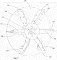
- Fig. 5 shows an exemplary throwing wheel 100 with throwing wings 200 and a protective screen 400, which is rotatably connected to the throwing wheel 100 and is usually arranged on the side facing away from the inlet opening 310 of the throwing wheel 100 , which is in Fig. 2 is more clearly apparent.
- the radius of the protective disk 400 corresponds at least to the radial extent of a throwing blade 200, wherein the radius of the protective disk 400 in FIG Fig. 5 between the radially outermost end of a throwing blade 200 and the radially outermost end of the unfolded end portion 230 of this throwing blade 200 , ie, the end pieces 230 of the protective plate 400 project in the radial direction.
- Fig. 6 shows the profile of the throwing wheel Fig. 5 , where it can be clearly seen that there is no space between the throwing wheel 100 and the throwing blades 200 and the protective screen 400 .
- Fig. 7 shows a perspective view of the throwing wheel FIGS. 5 and 6 Wherein in this view, the stop projections 220 and their arrangement are better visible.
- a further exemplary embodiment of a protective plate 400 is shown, wherein the protective plate 400 has openings 410 which are arranged between adjacent in the circumferential direction of the protective disc 400 Wurfulateln 200 .
- Such openings 410 may serve as maintenance openings, so that not the entire throwing wheel 100 has to be removed during repairs.
- a corresponding cover 420 is provided for each opening 410 , which can be fastened to the protective screen 400 with a fastening means 430 .
- fastening means 430 for example screws may be provided, as in Fig. 8 you can see.
- covers 420 may protrude a millimeter from the protective screen 400 in the direction of an adjacent wall of the housing drum 300 , this automatically also frees or cleans the gap between the protective screen 400 and the adjacent wall of the housing drum 300 of deposited chips or woodchip dust.
- the covers 420 each have a smaller thickness than the protective screen 400 .
- the total weight of the protective screen 400 can be reduced while the functionality of the protective screen 400 remains the same .
- Fig. 10 shows a partial perspective view of a throwing wheel 100 with a cover 410 and covers 420 having protective plate 400.
- the end pieces 230 is secured by a holding means 231 on the blade surface 410 , such a holder requires an increased force by wood chips to break.
- the holding means 231 can therefore be interpreted as a desired predetermined breaking point.
- the support means 231 such as screws, chosen so that they break and the corresponding end piece 230 can dodge against the direction of rotation of the throwing wheel 100 , as already described above, before the throwing wheel 100 is blocked or obstructed in its rotational movement.
- At least one blade surface 210 can have a guide projection 250 projecting in the direction of rotation, which runs obliquely on the blade surface 210 Inlet opening 310 facing away from the blade surface 210 is aligned, as in FIGS. 11 and 12 you can see.
- the guide projection 250 conveys the woodchip during the rotational movement of the throwing wheel 100 and the resulting centrifugal force further in the direction of the inlet opening 310 side facing away from the throwing blade 200 and the respective blade surface 210, whereby the ejection of the wood chips through the outlet opening 320 a more uniform and targeted throwing beam is produced.
Landscapes
- Engineering & Computer Science (AREA)
- Mechanical Engineering (AREA)
- Debarking, Splitting, And Disintegration Of Timber (AREA)
Abstract
Description
- Die Erfindung betrifft eine Wurfvorrichtung zum Auswerfen von Hackgut, umfassend ein durch ein Antriebsmittel in Rotation um eine Drehachse versetzbares Wurfrad mit Schaufelflächen aufweisenden Wurfflügeln, wobei das Wurfrad von einer Gehäusetrommel umgeben ist, die eine zur Zufuhr des Hackguts vorgesehene Eintrittsöffnung und eine Austrittsöffnung zum Auswurf des Hackguts aufweist, wobei im Betrieb der Wurfvorrichtung die Wurfflügel des in Rotation versetzten Wurfrades das über die Eintrittsöffnung zugeführte Hackgut erfassen und durch die Austrittsöffnung auswerfen.
- Das Hackgut, welches üblicherweise durch entsprechende Holzhackmaschinen in normgerechten Größen hergestellt wurde, wird einer Wurfvorrichtung zugeführt, wobei das Hackgut mit Hilfe des Wurfrades sowie den daran angeordneten Wurfflügeln auf ein nächst gelegenes Transportmittel ausgeworfen wird. Die normgerechte Größe des Hackguts soll dabei beibehalten werden.
- Zwischen dem Wurfrad und der Gehäusetrommel ist ein möglichst geringer Abstand vorgesehen, der es erlaubt, dass das Wurfrad bzw. die Wurfflügel eine Drehbewegung ausführt ohne an der Gehäusetrommel zu reiben und Verluste bei der Fördermenge gering zu halten.
- Es kann jedoch vorkommen, dass Hackgut während des Auswurfvorgangs in den Zwischenraum zwischen Gehäusetrommel und Wurfflügel gelangt, wobei das verhakte Hackgut je nach Größe und Form durch die ausübende Kraft des rotierenden Wurfrades weiter zerkleinert bzw. zerrieben wird und aufgrund der entstehenden Reibwirkung die Drehleistung des Wurfrades drosselt.
- Das oben beschriebene Zerkleinern bzw. Zerreiben erzeugt darüber hinaus Feinstaub aus Holz, der über die Wurfvorrichtung ebenso mit dem übrigen Hackgut ausgeworfen wird und bei einer späteren Anwendung als Brennstoff die Heizleistung vermindert.
- Es ist eine Aufgabe der Erfindung eine verbesserte Wurfvorrichtung bereitzustellen, die ein Zerkleinern bzw. Zerreiben des Hackguts vermindert.
- Diese Aufgabe wird dadurch gelöst, dass zumindest ein Wurfflügel zumindest ein von der jeweiligen Schaufelfläche separates Endstück aufweist, welches verschwenkbar ist und dessen Ausrichtung bzw. Position von einem eingeklappten Zustand bis hin zu einem vollständig ausgeklappten Zustand veränderbar ist, wobei das Endstück im eingeklappten Zustand der jeweiligen Schaufelfläche in radialer Erstreckung zumindest zum Teil übersteht.
- Durch die klappbaren bzw. verschwenkbaren Endstücke ist ein Verkanten des Hackguts zwischen den Wurfflügeln und der Gehäusetrommel weitestgehend ausgeschlossen, da die Endstücke zurückweichen können.
- Hierbei kann vorgesehen sein, dass das zumindest eine Endstück in Form einer Platte ausgebildet ist.
- Ebenso bei Fremdkörpereinwirkung, insbesondere durch metallische Gegenstände, die in dem zum Hacken in der Holzhackmaschine vorgesehenen Holz vorhanden sein können, beispielsweise Nägel oder Schrauben, weichen die Endstücke zurück, wobei kein Schaden am Wurfrad bzw. an den Wurfflügeln entsteht.
- Unter einem vollständig ausgeklappten Zustand ist zu verstehen, dass sich das zumindest eine Endstück in einer solchen Position befindet, dass eine weitere Bewegung des Endstücks gegen die Drehrichtung des Wurfrades nicht mehr möglich ist.
- Es kann vorgesehen sein, dass sich das zumindest eine Endstück im Betrieb der Wurfvorrichtung aufgrund der durch die Rotationsbewegung erzeugten Zentrifugalkraft in den eingeklappten Zustand ausrichtet.
- Weiterhin ist es vorteilhaft, wenn das zumindest eine Endstück aus Metall gefertigt ist bzw. aus einem Material, welches ungefähr der Dichte eines Metalls entspricht.
- Insbesondere ist das Endstück aus einem Material gefertigt, welches ein solches Gewicht besitzt, dass sich das Endstück bei einer Rotationsbewegung des Wurfrades in radialer Richtung zur Drehachse ausrichtet, wobei der durch eine plattenförmige Gestalt des Endstücks und durch die Rotation einwirkende Luftwiderstand vernachlässigbar ist, zumindest in einer Weise vernachlässigbar, dass der einwirkende Luftwiderstand einer Ausrichtung des Endstücks radial zur Drehachse nicht entgegenwirkt.
- Vorzugsweise können am radial äußeren Ende des zumindest einen Endstücks - gesehen in einem eingeklappten Zustand des Endstücks - Vorsprünge angeordnet sein. Diese bewirken, dass durch die Drehbewegung erzeugte Geräusche gemindert werden.
- Weiters kann vorgesehen sein, dass das zumindest eine Endstück bei durch Hackgut erzeugter Krafteinwirkung gegen die Drehrichtung des Wurfrades in Richtung des ausgeklappten Zustands nachgeben kann.
- Hierbei ist gemeint, dass das zumindest eine Endstück erst dann nachgibt, wenn die durch Hackgut erzeugte Krafteinwirkung die Kraft, welche das zumindest eine Endstück in der Position des eingeklappten Zustands hält bzw. ausrichtet, übertrifft und so entgegenwirkt, dass das zumindest eine Endstück in Richtung des ausgeklappten Zustands bzw. des vollständig ausgeklappten Zustands zurückweicht.
- Es kann günstig sein, wenn das zumindest eine Endstück zumindest ein Stellmittel aufweist, wobei sich das zumindest eine Endstück im außerbetrieblichen Zustand der Vorrichtung aufgrund des Stellmittels bereits in dem eingeklappten Zustand befindet.
- Dabei kann es ferner günstig sein, wenn das zumindest eine Stellmittel bei einer durch Hackgut erzeugten Krafteinwirkung gegen die Drehrichtung des Wurfrades nachgeben kann und das zumindest eine Endstück in Richtung des ausgeklappten Zustands ausweicht.
- Es kann vorgesehen sein, dass das Stellmittel in Form einer oder mehrerer Schrauben ausgebildet ist, wobei das zumindest eine Endstück an der entsprechenden Schaufelfläche des zumindest einen Wurfflügels angeschraubt ist. Die zuvor beschriebene erforderliche Krafteinwirkung durch Hackgut, welche ermöglicht, dass das zumindest eine Endstück in Richtung des ausgeklappten Zustands ausweicht, ist durch das verwendete Stellmittel erhöht.
- Beim Erreichen dieser erforderlichen Kraft durch Hackgut, bricht die eine oder brechen die mehreren Schrauben und geben das zumindest eine Endstück gewissermaßen frei, sodass sich das Endstück in Richtung des ausgeklappten Zustands bewegen kann.
- Es kann auch vorgesehen sein, dass das Stellelement in Form von einem oder mehreren elastischen Federelementen ausgebildet ist.
- Es kann vorgesehen sein, dass der zumindest eine Wurfflügel einen Anschlag aufweist, der eine Bewegung des Endstücks gegen die Drehrichtung des Wurfrades begrenzt.
- Dieser Anschlag bestimmt im Wesentlichen die Position des vollständig ausgeklappten Zustands des zumindest einen Endstücks.
- Es kann ferner vorgesehen sein, dass das zumindest eine Endstück in seinem vollständig ausgeklappten Zustand einer gedachten, durch die Drehbewegung des radial äußersten Punktes des jeweiligen Wurfflügels um die Drehachse beschriebenen Kreislinie nicht übersteht.
- So kann ein Stück des Hackguts, welches aufgrund seiner Größe die Lücke zwischen Gehäusetrommel und dem radial äußersten Ende des jeweiligen Wurfflügels passieren kann, durch das zurückweichende bzw. gegen die Drehrichtung klappbare Endstück, dessen Abstand zur Gehäusetrommel geringer ausfällt, von dem nächsten Wurfflügel erfasst werden, ohne dass sich dieses Stück des Hackguts in der Lücke zwischen Gehäusetrommel und Endstück verhakt bzw. stecken bleibt.
- Dabei kann vorgesehen sein, dass der Abstand des radial äußersten Endes der Wurfflügel zur Gehäusetrommel im Wesentlichen der normgerechten Größe des jeweiligen Hackguts entspricht, wobei der Abstand je nach entsprechender Normgröße des Hackguts variieren kann.
- Dadurch kann die Wahrscheinlichkeit des Blockierens der Wurfflügel bzw. des Wurfrades durch Hackgut um ein Vielfaches minimiert werden.
- Auch beim Beschleunigen des Wurfrades ist dies von Vorteil, da durch den kleineren Durchmesser eine geringere Massenträgheit vorhanden ist.
- Mit Vorteil kann vorgesehen sein, wenn mehrere, vorzugsweise jeder Wurfflügel zumindest ein Endstück aufweist.
- Es kann auch vorgesehen sein, dass mehrere, vorzugsweise jeder Wurfflügel zumindest zwei oder mehrere Endstücke aufweist.
- Vorteilhafterweise kann die Wurfvorrichtung ferner eine Schutzscheibe umfassen, die auf der der Eintrittsöffnung abgewandten Seite des Wurfrades angeordnet ist.
- Dadurch soll eine Nachzerkleinerung (Verkanten bzw. Verhaken des Hackguts) in dem jeweiligen Spalt zwischen Wurfflügel und einer Gehäusetrommelwand, welche der Eintrittsöffnung abgewandt ist, vermieden werden.
- Dabei kann die Schutzscheibe drehfest mit dem Wurfrad verbunden sein. Vorzugsweise ist das Wurfrad bzw. sind die Wurfflügel an der Schutzscheibe angeschweißt.
- Es kann ferner günstig sein, wenn der Radius der Schutzscheibe mindestens der radialen Ausdehnung eines Wurfflügels entspricht.
- Mit Vorteil kann vorgesehen sein, wenn die Schutzscheibe zumindest eine Öffnung aufweist, welche im Bereich zwischen in Umfangsrichtung der Schutzscheibe benachbarten Wurfflügeln angeordnet ist.
- Ebenso kann vorgesehen sein, wenn die Schutzscheibe im Bereich zwischen in Umfangsrichtung der Schutzscheibe benachbarten Wurfflügeln eine Öffnung aufweist.
- Hierbei kann es günstig sein, wenn die Schutzscheibe ferner zu jeder Öffnung eine korrespondierende Abdeckung aufweist, welche mit einem Befestigungsmittel an der Schutzscheibe befestigbar ist.
- Solche Öffnungen können als Wartungsöffnungen dienen, sodass nicht das komplette Wurfrad ausgebaut werden muss. Hierzu wird lediglich die entsprechende Abdeckung abgenommen.
- Es kann ferner vorgesehen sein, dass die Abdeckung eine geringere Dicke als die Schutzscheibe aufweist.
- Dadurch kann das Gesamtgewicht der Schutzscheibe verringert werden bei gleichbleibender vorgesehener Funktionalität der Schutzscheibe.
- In einer zweckmäßigen Ausführungsform können die Wurfflügel radial bzw. sternförmig um die Drehachse angeordnet sein.
- Es kann günstig sein, wenn die Schaufelflächen orthogonal zur Drehrichtung positioniert sind.
- Vorteilhafterweise können die Schaufelflächen in ihrer flächenhaften Ausdehnung in Richtung der Drehachse eine Verjüngung aufweisen.
- Es kann günstig sein, wenn zumindest ein Wurfflügel zumindest einen in Drehrichtung vorstehenden Begrenzungsvorsprung aufweist.
- Dies gewährleistet, dass das Hackgut beim Zuführen durch die Eintrittsöffnung besser durch die jeweilige Schaufelfläche erfasst wird und mehr Hackgut pro Wurfflügel ausgeworfen werden kann.
- Ebenso kann es günstig sein, wenn zumindest ein Wurfflügel auf seiner der Schutzscheibe abgewandten Seite einen in Drehrichtung vorstehenden Begrenzungsvorsprung aufweist, der im Wesentlichen dem Kantenverlauf der Schaufelfläche folgt.
- Mit Vorteil kann vorgesehen sein, wenn zumindest eine Schaufelfläche einen in Drehrichtung vorstehenden Führungsvorsprung aufweist, welcher auf der Schaufelfläche schräg zulaufend zur Eintrittsöffnung abgewandten Seite ausgerichtet ist.
- Ein solcher Führungsvorsprung befördert das Hackgut, während der Drehbewegung des Wurfrads und der dadurch entstehenden Zentrifugalkraft weiter in Richtung der der Eintrittsöffnung abgewandten Seite des Wurfflügels, wodurch beim Auswurf des Hackguts ein gleichmäßigerer und gezielter Wurfstrahl erzeugt wird.
- Nachfolgend wird die Erfindung anhand von beispielhaften Zeichnungen näher erläutert. Hierbei zeigt
-
Fig. 1 eine Seitenansicht einer beispielhaften Wurfvorrichtung, -
Fig. 2 einen Querschnitt durch den Schnitt III-III vonFig. 1 , -
Fig. 3 ein beispielhaftes Wurfrad mit einem maximal ausgeklappten Endstück, -
Fig. 4 eine Detailansicht des maximal ausgeklappten Endstücks ausFig. 3 , -
Fig. 5 ein beispielhaftes Wurfrad mit Wurfflügeln und einer Schutzscheibe, -
Fig. 6 eine Seitenansicht des Wurfrades ausFig. 5 , -
Fig. 7 eine perspektivische Ansicht eines beispielhaften Wurfrades, -
Fig. 8 eine perspektivische Ansicht eines beispielhaften Wurfrades mit einer Öffnungen und Abdeckungen aufweisenden Schutzscheibe, -
Fig. 9 eine rückwärtige Ansicht des Wurfrades ausFig. 8 , -
Fig. 10 eine weitere perspektivische Teilansicht des Wurfrades ausFig. 8 und 9 , -
Fig. 11 eine weitere Teilansicht des Wurfrades ausFig. 8, 9 und10 , und -
Fig. 12 eine Draufsicht eines Wurfflügels aus dem beispielhaften Wurfrad ausFig. 8, 9 ,10 und 11 mit einem auf einer Schaufelfläche angeordneten Führungsvorsprung. -
Fig. 1 zeigt eine Seitenansicht einer beispielhaften Wurfvorrichtung 50 zum Auswerfen von Hackgut, umfassend ein durch ein Antriebsmittel, welches in den Figuren nicht gezeigt ist, in Rotation um eine Drehachse X versetzbares Wurfrad 100 mit Schaufelflächen 210 aufweisenden Wurfflügeln 200, wobei das Wurfrad 100 von einer Gehäusetrommel 300 umgeben ist, die eine zur Zufuhr des Hackguts vorgesehene Eintrittsöffnung 310 und eine Austrittsöffnung 320 zum Auswurf des Hackguts aufweist. - Als Antriebsmittel kann beispielsweise ein Keilriemenantrieb, Hydraulikantrieb oder ein Getriebeantrieb, insbesondere ein Planetengetriebe, vorgesehen sein.
- Die Wurfflügel 200 sind radial bzw. sternförmig um die Drehachse X an dem Wurfrad 100 angeordnet, wobei jeder Wurfflügel 200 eine im Wesentlichen orthogonal zur Drehrichtung angeordnete Schaufelfläche 210 aufweist. Von den in
Fig. 1 gezeigten Wurfflügeln 200 weisen drei Wurfflügel 200 einen in Drehrichtung vorstehenden Begrenzungsvorsprung 220 auf. In einer weiteren Ausführungsform kann jedoch auch vorgesehen sein, dass alle oder zumindest ein Wurfflügel 200 einen Begrenzungsvorsprung 220 aufweist. - Die Begrenzungsvorsprünge 220 gewährleisten, dass das Hackgut beim Zuführen durch die Eintrittsöffnung 310 besser durch die jeweilige Schaufelfläche 210 erfasst wird und mehr Hackgut pro Wurfflügel 200 ausgeworfen werden kann.
- Weiters wird das Hackgut weniger nachzerkleinert, da weniger Reibung zwischen der jeweiligen Schaufelfläche 210 und der Gehäusetrommel 300 entsteht.
- Ferner weisen die Wurfflügel 200 an ihrem radial äußeren Endabschnitt ein schwenkbar gelagertes Endstück 230 auf, welches eingerichtet ist, sich im Betrieb der Wurfvorrichtung 50 aufgrund der durch die Rotationsbewegung des Wurfrades 100 erzeugten Zentrifugalkraft in radialer Richtung zur Drehachse X des Wurfrades 100 auszurichten und dem jeweiligen Wurfflügel 200 in radialer Erstreckung überzustehen, und ferner bei einer der Ausrichtung in radialer Richtung zur Drehachse X entgegenwirkenden Krafteinwirkung durch Hackgut gegen die Drehrichtung des Wurfrades 100 nachzugeben.
- Damit das jeweilige Endstück 230 bei Krafteinwirkung nachgibt, muss diese Krafteinwirkung so hoch sein, dass sie die Ausrichtung des Endstücks 230 in radialer Richtung zur Drehachse X durch die Zentrifugalkraft zumindest behindert.
- Die Endstücke 230 in
Fig. 1 befinden sich in einem ausgeklappten Zustand und verlaufen parallel zur Schaufelfläche 210 des jeweiligen Wurfflügels 200. - Wie unter anderem in
Fig. 2 zu sehen ist, welche einen Querschnitt durch den Schnitt III-III ausFig. 1 zeigt, weisen die Schaufelflächen 210 in ihrer flächenhaften Ausdehnung in Richtung der Drehachse X eine Verjüngung auf. Weiters ist ersichtlich, dass die Begrenzungsvorsprünge 220 auf der der Eintrittsöffnung 310 zugewandten Seite angeordnet sind und im Wesentlichen dem Kantenverlauf der jeweiligen Schaufelfläche 210 folgt. - In einer weiteren Ausführungsform kann vorgesehen sein, dass die Begrenzungsvorsprünge 220 sowohl auf der der Eintrittsöffnung 310 zugewandten als auch abgewandten Seite der Schaufelflächen 210 angeordnet sind.
-
Fig. 3 zeigt einen Endabschnitt 230, der in einem maximal eingeklappten Zustand einer gedachten, durch die Drehbewegung des radial äußersten Punktes des jeweiligen Wurfflügels 200 beschriebenen Kreislinie nicht übersteht. Hierzu kann ein Anschlag 240 vorgesehen sein, welcher auf der Rückseite der jeweiligen Schaufelflächen 210 angeordnet ist und Bewegung des Endstücks 230 gegen die Drehrichtung des Wurfrades 100 begrenzt. - In
Fig. 3 ist ein Teil des durch den entsprechenden Wurfflügel 200 beschriebenen Kreises eingezeichnet.Fig. 4 zeigt eine Detailansicht des eingeklappten Endabschnitts 230 ausFig. 3 . -
Fig. 5 zeigt ein beispielhaftes Wurfrad 100 mit Wurfflügeln 200 und einer Schutzscheibe 400, die drehfest mit dem Wurfrad 100 verbunden ist und in der Regel auf der der Eintrittsöffnung 310 abgewandten Seiten des Wurfrades 100 angeordnet ist, was inFig. 2 genauer ersichtlich ist. Ferner entspricht der Radius der Schutzscheibe 400 mindestens der radialen Ausdehnung eines Wurfflügels 200, wobei der Radius der Schutzscheibe 400 inFig. 5 zwischen dem radial äußersten Ende eines Wurfflügels 200 und dem radial äußersten Ende des ausgeklappten Endabschnitts 230 dieses Wurfflügels 200 liegt, d.h. die Endstücke 230 der Schutzscheibe 400 in radialer Richtung überstehen.Fig. 6 zeigt das Profil des Wurfrades ausFig. 5 , wobei hier eindeutig zu sehen ist, dass kein Zwischenraum Wurfrad 100 bzw. Wurfflügeln 200 und der Schutzscheibe 400 vorhanden ist. -
Fig. 7 zeigt eine perspektivische Ansicht des Wurfrades ausFig. 5 und 6 , wobei in dieser Ansicht die Begrenzungsvorsprünge 220 und deren Anordnung besser ersichtlich sind. - In
Fig. 8 und 9 ist eine weitere beispielhafte Ausführung einer Schutzscheibe 400 dargestellt, wobei die Schutzscheibe 400 Öffnungen 410 aufweist, die zwischen in Umfangsrichtung der Schutzscheibe 400 benachbarten Wurfflügeln 200 angeordnet sind. - Solche Öffnungen 410 können als Wartungsöffnungen dienen, sodass nicht das komplette Wurfrad 100 bei Reparaturen ausgebaut werden muss.
- Um die Funktionalität der Schutzscheibe 400 weiterhin zu gewährleisten, ist zu jeder Öffnung 410 eine dazu korrespondierende Abdeckung 420 vorgesehen, welche mit einem Befestigungsmittel 430 an der Schutzscheibe 400 befestigbar ist. Als Befestigungsmittel 430 können beispielsweise Schrauben vorgesehen sein, wie in
Fig. 8 zu sehen ist. - Da die Abdeckungen 420 eine Millimeter von der Schutzscheibe 400 in Richtung einer angrenzenden Wand der Gehäusetrommel 300 vorstehen können, wird hierdurch auch automatisch der Zwischenraum zwischen Schutzscheibe 400 und der angrenzenden Wand der Gehäusetrommel 300 von abgelagerten Hackschnitzeln bzw. Hackschnitzelstaub befreit bzw. gereinigt.
- Es ist vorteilhaft, wenn die Abdeckungen 420 jeweils eine geringere Dicke als die Schutzscheibe 400 aufweisen. Dadurch kann das Gesamtgewicht der Schutzscheibe 400 verringert werden bei gleichbleibender vorgesehener Funktionalität der Schutzscheibe 400.
-
Fig. 10 zeigt eine perspektivische Teilansicht eines Wurfrades 100 mit einer Öffnungen 410 und Abdeckungen 420 aufweisenden Schutzscheibe 400. In diesem Beispiel ist zu sehen, dass die Endstücke 230 mittels einem Halterungsmittel 231 an der Schaufelfläche 410 befestigt ist, wobei eine solche Halterung eine erhöhte Krafteinwirkung durch Hackgut erfordert, um zu brechen. Das Halterungsmittel 231 kann demnach als gewollte Sollbruchstelle interpretiert werden. - Bei einem möglichen Einklemmen von Hackgut zwischen dem Endstück 230 und der Gehäusetrommel 300 ist das Halterungsmittel 231, beispielsweise Schrauben, so gewählt, dass diese brechen und das entsprechende Endstück 230 gegen die Drehrichtung des Wurfrades 100 ausweichen kann, wie oben bereits beschrieben, bevor das Wurfrades 100 in seiner Drehbewegung blockiert bzw. behindert wird.
- Weiters kann zumindest eine Schaufelfläche 210 einen in Drehrichtung vorstehenden Führungsvorsprung 250 aufweisen, welcher auf der Schaufelfläche 210 schräg zulaufend zur Eintrittsöffnung 310 abgewandten Seite der Schaufelfläche 210 ausgerichtet ist, wie in
Fig. 11 und 12 zu sehen ist. - Der Führungsvorsprung 250 befördert das Hackgut während der Drehbewegung des Wurfrads 100 und der dadurch entstehenden Zentrifugalkraft weiter in Richtung der der Eintrittsöffnung 310 abgewandten Seite des Wurfflügels 200 bzw. der jeweiligen Schaufelfläche 210, wodurch beim Auswurf des Hackguts über die Austrittsöffnung 320 ein gleichmäßigerer und gezielter Wurfstrahl erzeugt wird.
BEZUGSZEICHENLISTE Wurfvorrichtung... 50 Wurfrad... 100 Wurfflügel... 200 Schaufelflächen... 210 Begrenzungsvorsprung... 220 Endstück... 230 Halterungsmittel... 231 Anschlag... 240 Führungsvorsprung... 250 Gehäusetrommel... 300 Eintrittsöffnung... 310 Austrittsöffnung... 320 Schutzscheibe... 400 Öffnungen... 410 Abdeckung... 420 Befestigungsmittel... 430 Drehachse... X
Claims (15)
- Wurfvorrichtung (50) zum Auswerfen von Hackgut, umfassend ein durch ein Antriebsmittel in Rotation um eine Drehachse (X) versetzbares Wurfrad (100) mit Wurfflügeln (200), welche zumindest eine Schaufelfläche (210) aufweisen, wobei das Wurfrad (100) von einer Gehäusetrommel (300) umgeben ist, die eine zur Zufuhr des Hackguts vorgesehene Eintrittsöffnung (310) und eine Austrittsöffnung (320) zum Auswurf des Hackguts aufweist, wobei im Betrieb der Wurfvorrichtung die Wurfflügel (200) des in Rotation versetzten Wurfrades (100) das über die Eintrittsöffnung (310) zugeführte Hackgut erfassen und durch die Austrittsöffnung (320) auswerfen,
dadurch gekennzeichnet, dass
zumindest ein Wurfflügel (200) zumindest ein von der jeweiligen Schaufelfläche (210) separates Endstück (230) aufweist, welches verschwenkbar ist und dessen Ausrichtung bzw. Position von einem eingeklappten Zustand bis hin zu einem vollständig ausgeklappten Zustand veränderbar ist, wobei das Endstück (230) im eingeklappten Zustand der jeweiligen Schaufelfläche (210) in radialer Erstreckung zumindest zum Teil übersteht. - Vorrichtung nach Anspruch 1, dadurch gekennzeichnet, dass das zumindest eine Endstück (230) sich im Betrieb der Wurfvorrichtung (50) aufgrund der durch die Rotationsbewegung des Wurfrades (100) erzeugten Zentrifugalkraft in den eingeklappten Zustand ausrichtet.
- Vorrichtung nach Anspruch 2, dadurch gekennzeichnet, dass das zumindest eine Endstück (230) bei durch Hackgut erzeugter Krafteinwirkung gegen die Drehrichtung des Wurfrades (100) in Richtung des ausgeklappten Zustands nachgeben kann.
- Vorrichtung nach einem der Ansprüche 1 bis 3, dadurch gekennzeichnet, dass das zumindest eine Endstück (230) zumindest ein Stellmittel (231) aufweist, wobei sich das zumindest eine Endstück (230) im außerbetrieblichen Zustand der Vorrichtung (50) aufgrund des Stellmittels (231) in dem eingeklappten Zustand befindet, wobei vorzugsweise das zumindest eine Stellmittel (231) bei einer durch Hackgut erzeugten Krafteinwirkung gegen die Drehrichtung des Wurfrades (100) nachgeben kann und das zumindest eine Endstück (230) in Richtung des ausgeklappten Zustands ausweicht.
- Vorrichtung nach einem der Ansprüche 1 bis 4, dadurch gekennzeichnet, dass der zumindest ein Wurfflügel (200) einen Anschlag (240) aufweist, der eine Bewegung des Endstücks (230) gegen die Drehrichtung des Wurfrades (100) begrenzt.
- Vorrichtung nach einem der Ansprüche 1 bis 5, dadurch gekennzeichnet, dass das zumindest eine Endstück (230) in seinem vollständig ausgeklappten Zustand einer gedachten, durch die Drehbewegung des radial äußersten Punktes des jeweiligen Wurfflügels (200) um die Drehachse (X) beschriebenen Kreislinie nicht übersteht.
- Vorrichtung nach einem der Ansprüche 1 bis 6, dadurch gekennzeichnet, dass mehrere, vorzugsweise jeder Wurfflügel (200) zumindest ein Endstück (230) aufweist.
- Vorrichtung nach einem der Ansprüche 1 bis 7, dadurch gekennzeichnet, dass die Wurfvorrichtung (50) ferner eine Schutzscheibe (400) umfasst, die auf der der Eintrittsöffnung (310) abgewandten Seite des Wurfrades (100) angeordnet ist, wobei vorzugsweise die Schutzscheibe (400) drehfest mit dem Wurfrad (100) verbunden ist, wobei insbesondere der Radius der Schutzscheibe (400) mindestens der radialen Ausdehnung eines Wurfflügels (200) entspricht.
- Vorrichtung nach einem der Ansprüche 7 oder 8, dadurch gekennzeichnet, dass die Schutzscheibe (400) zumindest eine Öffnung (410) aufweist, welche im Bereich zwischen in Umfangsrichtung der Schutzscheibe (400) benachbarten Wurfflügeln (200) angeordnet ist, wobei vorzugsweise die Schutzscheibe (400) im Bereich zwischen in Umfangsrichtung der Schutzscheibe (400) benachbarten Wurfflügeln (200) eine Öffnung (410) aufweist.
- Vorrichtung nach Anspruch 8 oder 9, dadurch gekennzeichnet, dass die Schutzscheibe (400) ferner zu jeder Öffnung (410) eine korrespondierende Abdeckung (420) aufweist, welche mit einem Befestigungsmittel (430), beispielsweise Schrauben, an der Schutzscheibe (400) befestigbar ist, wobei vorzugsweise die Abdeckung (420) eine geringere Dicke als die Schutzscheibe (400) aufweist.
- Vorrichtung nach einem der Ansprüche 1 bis 10, dadurch gekennzeichnet, dass die Wurfflügel (200) radial bzw. sternförmig um die Drehachse (X) angeordnet sind.
- Vorrichtung nach einem der Ansprüche 1 bis 11, dadurch gekennzeichnet, dass die Schaufelflächen (210) in ihrer flächenhaften Ausdehnung in Richtung der Drehachse (X) eine Verjüngung aufweisen.
- Vorrichtung nach einem der Ansprüche 1 bis 12, dadurch gekennzeichnet, dass zumindest ein Wurfflügel (200) zumindest einen in Drehrichtung vorstehenden Begrenzungsvorsprung (220) aufweist.
- Vorrichtung nach einem der Ansprüche 8 bis 13, dadurch gekennzeichnet, dass zumindest ein Wurfflügel (200) auf seiner der Schutzscheibe (400) abgewandten Seite einen in Drehrichtung vorstehenden Begrenzungsvorsprung (220) aufweist, der im Wesentlichen dem Kantenverlauf der Schaufelfläche (210) folgt.
- Vorrichtung nach einem der Ansprüche 1 bis 14, dadurch gekennzeichnet, dass zumindest eine Schaufelfläche (210) einen in Drehrichtung vorstehenden Führungsvorsprung (250) aufweist, welcher auf der Schaufelfläche (210) schräg zulaufend zur Eintrittsöffnung (310) abgewandten Seite ausgerichtet ist.
Applications Claiming Priority (1)
| Application Number | Priority Date | Filing Date | Title |
|---|---|---|---|
| ATA50717/2017A AT520377B1 (de) | 2017-08-29 | 2017-08-29 | Wurfvorrichtung zum Auswerfen von Hackgut |
Publications (2)
| Publication Number | Publication Date |
|---|---|
| EP3450357A1 true EP3450357A1 (de) | 2019-03-06 |
| EP3450357B1 EP3450357B1 (de) | 2020-02-19 |
Family
ID=62715879
Family Applications (1)
| Application Number | Title | Priority Date | Filing Date |
|---|---|---|---|
| EP18178694.8A Revoked EP3450357B1 (de) | 2017-08-29 | 2018-06-20 | Wurfvorrichtung zum auswerfen von hackgut |
Country Status (2)
| Country | Link |
|---|---|
| EP (1) | EP3450357B1 (de) |
| AT (1) | AT520377B1 (de) |
Cited By (3)
| Publication number | Priority date | Publication date | Assignee | Title |
|---|---|---|---|---|
| CN110077787A (zh) * | 2019-04-23 | 2019-08-02 | 王锡山 | 一种硅藻土选料抛送机装置 |
| CN113460590A (zh) * | 2020-03-31 | 2021-10-01 | 瑞轩科技股份有限公司 | 给料装置及抛掷装置 |
| US11758880B2 (en) | 2020-03-31 | 2023-09-19 | Amtran Technology Co., Ltd. | Object supplying assembly, object casting assembly and operation method of object distribution system |
Citations (4)
| Publication number | Priority date | Publication date | Assignee | Title |
|---|---|---|---|---|
| CH503639A (de) * | 1968-01-26 | 1971-02-28 | Aebi & Co Ag | Gebläse zur Förderung von Schüttgut |
| JPS55137906U (de) * | 1979-03-23 | 1980-10-01 | ||
| US5357877A (en) * | 1993-03-16 | 1994-10-25 | Nuesmeyer David L | Feed for particulate burners |
| EP2385006A1 (de) * | 2010-05-06 | 2011-11-09 | Helzomat-Gerätebau + Energiesysteme GmbH | Austragungsvorrichtung für kleinstückiges Schüttgut |
Family Cites Families (1)
| Publication number | Priority date | Publication date | Assignee | Title |
|---|---|---|---|---|
| DE1965670U (de) * | 1967-04-29 | 1967-08-03 | H & W Fritzen | Landwirtschaftliches foerdergeblaese. |
-
2017
- 2017-08-29 AT ATA50717/2017A patent/AT520377B1/de not_active IP Right Cessation
-
2018
- 2018-06-20 EP EP18178694.8A patent/EP3450357B1/de not_active Revoked
Patent Citations (4)
| Publication number | Priority date | Publication date | Assignee | Title |
|---|---|---|---|---|
| CH503639A (de) * | 1968-01-26 | 1971-02-28 | Aebi & Co Ag | Gebläse zur Förderung von Schüttgut |
| JPS55137906U (de) * | 1979-03-23 | 1980-10-01 | ||
| US5357877A (en) * | 1993-03-16 | 1994-10-25 | Nuesmeyer David L | Feed for particulate burners |
| EP2385006A1 (de) * | 2010-05-06 | 2011-11-09 | Helzomat-Gerätebau + Energiesysteme GmbH | Austragungsvorrichtung für kleinstückiges Schüttgut |
Cited By (3)
| Publication number | Priority date | Publication date | Assignee | Title |
|---|---|---|---|---|
| CN110077787A (zh) * | 2019-04-23 | 2019-08-02 | 王锡山 | 一种硅藻土选料抛送机装置 |
| CN113460590A (zh) * | 2020-03-31 | 2021-10-01 | 瑞轩科技股份有限公司 | 给料装置及抛掷装置 |
| US11758880B2 (en) | 2020-03-31 | 2023-09-19 | Amtran Technology Co., Ltd. | Object supplying assembly, object casting assembly and operation method of object distribution system |
Also Published As
| Publication number | Publication date |
|---|---|
| AT520377A1 (de) | 2019-03-15 |
| AT520377B1 (de) | 2021-06-15 |
| EP3450357B1 (de) | 2020-02-19 |
Similar Documents
| Publication | Publication Date | Title |
|---|---|---|
| DE3147634C2 (de) | Papierzerkleinerer und Verfahren zum Betrieb | |
| WO2016177358A1 (de) | Zerkleinerungsmaschine mit einem rotorsystem und verfahren zum zerkleinern von aufgabegut | |
| EP3450357A1 (de) | Wurfvorrichtung zum auswerfen von hackgut | |
| DE102020130055B4 (de) | Rührwerksmühle | |
| WO2017076795A1 (de) | Aufbereitungsvorrichtung, sowie aufbereitungselement und wandverkleidungselement für eine derartige aufbereitungsvorrichtung | |
| DE3807983C2 (de) | Vorrichtung zum Zerkleinern | |
| WO2013178818A1 (de) | Vorrichtung und verfahren zum zerkleinern von teilen oder gütern | |
| WO2014012693A2 (de) | Zerkleinerung von mahlgut in einer vertikalrollenmühle | |
| DE1272091C2 (de) | Hammerbrecher zum Zerkleinen von Abfaellen, insbesondere von metallischen Gegenstaenden | |
| DE3306068C2 (de) | Zerkleinerungsmaschine zur Herstellung von Holzspänen | |
| DE102010055786B4 (de) | Lochscheibensystem | |
| DE3211823C2 (de) | ||
| DE102015114122B3 (de) | Vorrichtung zum Abtragen von Bauwerkstoff | |
| DE102015014225A1 (de) | Mulchgerät | |
| EP2195268B1 (de) | Vorrichtungen zum auslegen von druckerzeugnissen auf einem transportband mit einem schaufelrad | |
| EP4117871B1 (de) | Schneidewerkzeug, insbesondere zum schneiden von flachen lebensmitteln | |
| EP2529834B1 (de) | Trommelschneidemaschine und Messerkorb für eine solche Maschine | |
| DE4431551C2 (de) | Brecher mit einem Gestell, in dem ein angetriebener, steinbrechender Rotor gelagert ist | |
| DE10140457C2 (de) | Mit Schneidmessern besetzte Schnecke eines Futtermischers | |
| AT392873B (de) | Haecksler | |
| DE3128565A1 (de) | Vorrichtung zum rundreduzieren des durchmessers von rundhoelzern | |
| EP1407655B1 (de) | Vorrichtung zur Schneidenöffnungswinkeleinstellung von beweglichen Messern an Zerkleinerungseinrichtungen | |
| DE10018005A1 (de) | Verfahren und Vorrichtung zum Pulverisieren von spanartigem Material | |
| DE102021133082B3 (de) | Vorrichtung zum fliehkraftschälen | |
| DE3229627A1 (de) | Messerwellenzerspanungssystem |
Legal Events
| Date | Code | Title | Description |
|---|---|---|---|
| PUAI | Public reference made under article 153(3) epc to a published international application that has entered the european phase |
Free format text: ORIGINAL CODE: 0009012 |
|
| STAA | Information on the status of an ep patent application or granted ep patent |
Free format text: STATUS: THE APPLICATION HAS BEEN PUBLISHED |
|
| AK | Designated contracting states |
Kind code of ref document: A1 Designated state(s): AL AT BE BG CH CY CZ DE DK EE ES FI FR GB GR HR HU IE IS IT LI LT LU LV MC MK MT NL NO PL PT RO RS SE SI SK SM TR |
|
| AX | Request for extension of the european patent |
Extension state: BA ME |
|
| STAA | Information on the status of an ep patent application or granted ep patent |
Free format text: STATUS: REQUEST FOR EXAMINATION WAS MADE |
|
| 17P | Request for examination filed |
Effective date: 20190711 |
|
| RBV | Designated contracting states (corrected) |
Designated state(s): AL AT BE BG CH CY CZ DE DK EE ES FI FR GB GR HR HU IE IS IT LI LT LU LV MC MK MT NL NO PL PT RO RS SE SI SK SM TR |
|
| GRAP | Despatch of communication of intention to grant a patent |
Free format text: ORIGINAL CODE: EPIDOSNIGR1 |
|
| STAA | Information on the status of an ep patent application or granted ep patent |
Free format text: STATUS: GRANT OF PATENT IS INTENDED |
|
| RIC1 | Information provided on ipc code assigned before grant |
Ipc: B65G 29/00 20060101AFI20190912BHEP Ipc: B65G 31/04 20060101ALI20190912BHEP Ipc: B65G 69/04 20060101ALI20190912BHEP |
|
| INTG | Intention to grant announced |
Effective date: 20191004 |
|
| GRAS | Grant fee paid |
Free format text: ORIGINAL CODE: EPIDOSNIGR3 |
|
| GRAA | (expected) grant |
Free format text: ORIGINAL CODE: 0009210 |
|
| STAA | Information on the status of an ep patent application or granted ep patent |
Free format text: STATUS: THE PATENT HAS BEEN GRANTED |
|
| AK | Designated contracting states |
Kind code of ref document: B1 Designated state(s): AL AT BE BG CH CY CZ DE DK EE ES FI FR GB GR HR HU IE IS IT LI LT LU LV MC MK MT NL NO PL PT RO RS SE SI SK SM TR |
|
| REG | Reference to a national code |
Ref country code: CH Ref legal event code: EP |
|
| REG | Reference to a national code |
Ref country code: DE Ref legal event code: R096 Ref document number: 502018000788 Country of ref document: DE |
|
| REG | Reference to a national code |
Ref country code: AT Ref legal event code: REF Ref document number: 1234726 Country of ref document: AT Kind code of ref document: T Effective date: 20200315 |
|
| REG | Reference to a national code |
Ref country code: IE Ref legal event code: FG4D Free format text: LANGUAGE OF EP DOCUMENT: GERMAN |
|
| REG | Reference to a national code |
Ref country code: NL Ref legal event code: MP Effective date: 20200219 |
|
| PG25 | Lapsed in a contracting state [announced via postgrant information from national office to epo] |
Ref country code: NO Free format text: LAPSE BECAUSE OF FAILURE TO SUBMIT A TRANSLATION OF THE DESCRIPTION OR TO PAY THE FEE WITHIN THE PRESCRIBED TIME-LIMIT Effective date: 20200519 Ref country code: FI Free format text: LAPSE BECAUSE OF FAILURE TO SUBMIT A TRANSLATION OF THE DESCRIPTION OR TO PAY THE FEE WITHIN THE PRESCRIBED TIME-LIMIT Effective date: 20200219 Ref country code: RS Free format text: LAPSE BECAUSE OF FAILURE TO SUBMIT A TRANSLATION OF THE DESCRIPTION OR TO PAY THE FEE WITHIN THE PRESCRIBED TIME-LIMIT Effective date: 20200219 |
|
| REG | Reference to a national code |
Ref country code: LT Ref legal event code: MG4D |
|
| PG25 | Lapsed in a contracting state [announced via postgrant information from national office to epo] |
Ref country code: HR Free format text: LAPSE BECAUSE OF FAILURE TO SUBMIT A TRANSLATION OF THE DESCRIPTION OR TO PAY THE FEE WITHIN THE PRESCRIBED TIME-LIMIT Effective date: 20200219 Ref country code: SE Free format text: LAPSE BECAUSE OF FAILURE TO SUBMIT A TRANSLATION OF THE DESCRIPTION OR TO PAY THE FEE WITHIN THE PRESCRIBED TIME-LIMIT Effective date: 20200219 Ref country code: LV Free format text: LAPSE BECAUSE OF FAILURE TO SUBMIT A TRANSLATION OF THE DESCRIPTION OR TO PAY THE FEE WITHIN THE PRESCRIBED TIME-LIMIT Effective date: 20200219 Ref country code: IS Free format text: LAPSE BECAUSE OF FAILURE TO SUBMIT A TRANSLATION OF THE DESCRIPTION OR TO PAY THE FEE WITHIN THE PRESCRIBED TIME-LIMIT Effective date: 20200619 Ref country code: BG Free format text: LAPSE BECAUSE OF FAILURE TO SUBMIT A TRANSLATION OF THE DESCRIPTION OR TO PAY THE FEE WITHIN THE PRESCRIBED TIME-LIMIT Effective date: 20200519 Ref country code: GR Free format text: LAPSE BECAUSE OF FAILURE TO SUBMIT A TRANSLATION OF THE DESCRIPTION OR TO PAY THE FEE WITHIN THE PRESCRIBED TIME-LIMIT Effective date: 20200520 |
|
| PG25 | Lapsed in a contracting state [announced via postgrant information from national office to epo] |
Ref country code: NL Free format text: LAPSE BECAUSE OF FAILURE TO SUBMIT A TRANSLATION OF THE DESCRIPTION OR TO PAY THE FEE WITHIN THE PRESCRIBED TIME-LIMIT Effective date: 20200219 |
|
| PG25 | Lapsed in a contracting state [announced via postgrant information from national office to epo] |
Ref country code: CZ Free format text: LAPSE BECAUSE OF FAILURE TO SUBMIT A TRANSLATION OF THE DESCRIPTION OR TO PAY THE FEE WITHIN THE PRESCRIBED TIME-LIMIT Effective date: 20200219 Ref country code: ES Free format text: LAPSE BECAUSE OF FAILURE TO SUBMIT A TRANSLATION OF THE DESCRIPTION OR TO PAY THE FEE WITHIN THE PRESCRIBED TIME-LIMIT Effective date: 20200219 Ref country code: SK Free format text: LAPSE BECAUSE OF FAILURE TO SUBMIT A TRANSLATION OF THE DESCRIPTION OR TO PAY THE FEE WITHIN THE PRESCRIBED TIME-LIMIT Effective date: 20200219 Ref country code: EE Free format text: LAPSE BECAUSE OF FAILURE TO SUBMIT A TRANSLATION OF THE DESCRIPTION OR TO PAY THE FEE WITHIN THE PRESCRIBED TIME-LIMIT Effective date: 20200219 Ref country code: LT Free format text: LAPSE BECAUSE OF FAILURE TO SUBMIT A TRANSLATION OF THE DESCRIPTION OR TO PAY THE FEE WITHIN THE PRESCRIBED TIME-LIMIT Effective date: 20200219 Ref country code: DK Free format text: LAPSE BECAUSE OF FAILURE TO SUBMIT A TRANSLATION OF THE DESCRIPTION OR TO PAY THE FEE WITHIN THE PRESCRIBED TIME-LIMIT Effective date: 20200219 Ref country code: PT Free format text: LAPSE BECAUSE OF FAILURE TO SUBMIT A TRANSLATION OF THE DESCRIPTION OR TO PAY THE FEE WITHIN THE PRESCRIBED TIME-LIMIT Effective date: 20200712 Ref country code: RO Free format text: LAPSE BECAUSE OF FAILURE TO SUBMIT A TRANSLATION OF THE DESCRIPTION OR TO PAY THE FEE WITHIN THE PRESCRIBED TIME-LIMIT Effective date: 20200219 Ref country code: SM Free format text: LAPSE BECAUSE OF FAILURE TO SUBMIT A TRANSLATION OF THE DESCRIPTION OR TO PAY THE FEE WITHIN THE PRESCRIBED TIME-LIMIT Effective date: 20200219 |
|
| REG | Reference to a national code |
Ref country code: DE Ref legal event code: R026 Ref document number: 502018000788 Country of ref document: DE |
|
| PLBI | Opposition filed |
Free format text: ORIGINAL CODE: 0009260 |
|
| PLAX | Notice of opposition and request to file observation + time limit sent |
Free format text: ORIGINAL CODE: EPIDOSNOBS2 |
|
| 26 | Opposition filed |
Opponent name: ESCHLBOECK-MASCHINENBAU GESELLSCHAFT M.B.H. Effective date: 20201118 |
|
| REG | Reference to a national code |
Ref country code: DE Ref legal event code: R119 Ref document number: 502018000788 Country of ref document: DE |
|
| PG25 | Lapsed in a contracting state [announced via postgrant information from national office to epo] |
Ref country code: MC Free format text: LAPSE BECAUSE OF FAILURE TO SUBMIT A TRANSLATION OF THE DESCRIPTION OR TO PAY THE FEE WITHIN THE PRESCRIBED TIME-LIMIT Effective date: 20200219 Ref country code: IT Free format text: LAPSE BECAUSE OF FAILURE TO SUBMIT A TRANSLATION OF THE DESCRIPTION OR TO PAY THE FEE WITHIN THE PRESCRIBED TIME-LIMIT Effective date: 20200219 |
|
| PG25 | Lapsed in a contracting state [announced via postgrant information from national office to epo] |
Ref country code: PL Free format text: LAPSE BECAUSE OF FAILURE TO SUBMIT A TRANSLATION OF THE DESCRIPTION OR TO PAY THE FEE WITHIN THE PRESCRIBED TIME-LIMIT Effective date: 20200219 Ref country code: SI Free format text: LAPSE BECAUSE OF FAILURE TO SUBMIT A TRANSLATION OF THE DESCRIPTION OR TO PAY THE FEE WITHIN THE PRESCRIBED TIME-LIMIT Effective date: 20200219 |
|
| PG25 | Lapsed in a contracting state [announced via postgrant information from national office to epo] |
Ref country code: LU Free format text: LAPSE BECAUSE OF NON-PAYMENT OF DUE FEES Effective date: 20200620 |
|
| REG | Reference to a national code |
Ref country code: BE Ref legal event code: MM Effective date: 20200630 |
|
| PG25 | Lapsed in a contracting state [announced via postgrant information from national office to epo] |
Ref country code: FR Free format text: LAPSE BECAUSE OF NON-PAYMENT OF DUE FEES Effective date: 20200630 Ref country code: IE Free format text: LAPSE BECAUSE OF NON-PAYMENT OF DUE FEES Effective date: 20200620 |
|
| PG25 | Lapsed in a contracting state [announced via postgrant information from national office to epo] |
Ref country code: BE Free format text: LAPSE BECAUSE OF NON-PAYMENT OF DUE FEES Effective date: 20200630 Ref country code: DE Free format text: LAPSE BECAUSE OF NON-PAYMENT OF DUE FEES Effective date: 20210101 |
|
| PLAY | Examination report in opposition despatched + time limit |
Free format text: ORIGINAL CODE: EPIDOSNORE2 |
|
| REG | Reference to a national code |
Ref country code: CH Ref legal event code: PL |
|
| PG25 | Lapsed in a contracting state [announced via postgrant information from national office to epo] |
Ref country code: LI Free format text: LAPSE BECAUSE OF NON-PAYMENT OF DUE FEES Effective date: 20210630 Ref country code: CH Free format text: LAPSE BECAUSE OF NON-PAYMENT OF DUE FEES Effective date: 20210630 |
|
| PLBC | Reply to examination report in opposition received |
Free format text: ORIGINAL CODE: EPIDOSNORE3 |
|
| PG25 | Lapsed in a contracting state [announced via postgrant information from national office to epo] |
Ref country code: TR Free format text: LAPSE BECAUSE OF FAILURE TO SUBMIT A TRANSLATION OF THE DESCRIPTION OR TO PAY THE FEE WITHIN THE PRESCRIBED TIME-LIMIT Effective date: 20200219 Ref country code: MT Free format text: LAPSE BECAUSE OF FAILURE TO SUBMIT A TRANSLATION OF THE DESCRIPTION OR TO PAY THE FEE WITHIN THE PRESCRIBED TIME-LIMIT Effective date: 20200219 Ref country code: CY Free format text: LAPSE BECAUSE OF FAILURE TO SUBMIT A TRANSLATION OF THE DESCRIPTION OR TO PAY THE FEE WITHIN THE PRESCRIBED TIME-LIMIT Effective date: 20200219 |
|
| PG25 | Lapsed in a contracting state [announced via postgrant information from national office to epo] |
Ref country code: MK Free format text: LAPSE BECAUSE OF FAILURE TO SUBMIT A TRANSLATION OF THE DESCRIPTION OR TO PAY THE FEE WITHIN THE PRESCRIBED TIME-LIMIT Effective date: 20200219 Ref country code: AL Free format text: LAPSE BECAUSE OF FAILURE TO SUBMIT A TRANSLATION OF THE DESCRIPTION OR TO PAY THE FEE WITHIN THE PRESCRIBED TIME-LIMIT Effective date: 20200219 |
|
| RDAF | Communication despatched that patent is revoked |
Free format text: ORIGINAL CODE: EPIDOSNREV1 |
|
| REG | Reference to a national code |
Ref country code: DE Ref legal event code: R103 Ref document number: 502018000788 Country of ref document: DE Ref country code: DE Ref legal event code: R064 Ref document number: 502018000788 Country of ref document: DE |
|
| RDAG | Patent revoked |
Free format text: ORIGINAL CODE: 0009271 |
|
| STAA | Information on the status of an ep patent application or granted ep patent |
Free format text: STATUS: PATENT REVOKED |
|
| REG | Reference to a national code |
Ref country code: CH Ref legal event code: PL |
|
| 27W | Patent revoked |
Effective date: 20221208 |
|
| GBPR | Gb: patent revoked under art. 102 of the ep convention designating the uk as contracting state |
Effective date: 20221208 |
|
| REG | Reference to a national code |
Ref country code: AT Ref legal event code: MA03 Ref document number: 1234726 Country of ref document: AT Kind code of ref document: T Effective date: 20221208 |
|
| PG25 | Lapsed in a contracting state [announced via postgrant information from national office to epo] |
Ref country code: GB Free format text: LAPSE BECAUSE OF NON-PAYMENT OF DUE FEES Effective date: 20220620 |
|
| PGFP | Annual fee paid to national office [announced via postgrant information from national office to epo] |
Ref country code: AT Payment date: 20260410 Year of fee payment: 5 |