EP3451886B1 - Bodenbehandlungssystem - Google Patents
Bodenbehandlungssystem Download PDFInfo
- Publication number
- EP3451886B1 EP3451886B1 EP16721784.3A EP16721784A EP3451886B1 EP 3451886 B1 EP3451886 B1 EP 3451886B1 EP 16721784 A EP16721784 A EP 16721784A EP 3451886 B1 EP3451886 B1 EP 3451886B1
- Authority
- EP
- European Patent Office
- Prior art keywords
- liquid
- container
- floor treatment
- opening
- treatment system
- Prior art date
- Legal status (The legal status is an assumption and is not a legal conclusion. Google has not performed a legal analysis and makes no representation as to the accuracy of the status listed.)
- Active
Links
Images



Classifications
-
- A—HUMAN NECESSITIES
- A47—FURNITURE; DOMESTIC ARTICLES OR APPLIANCES; COFFEE MILLS; SPICE MILLS; SUCTION CLEANERS IN GENERAL
- A47L—DOMESTIC WASHING OR CLEANING; SUCTION CLEANERS IN GENERAL
- A47L11/00—Machines for cleaning floors, carpets, furniture, walls, or wall coverings
- A47L11/40—Parts or details of machines not provided for in groups A47L11/02 - A47L11/38, or not restricted to one of these groups, e.g. handles, arrangements of switches, skirts, buffers, levers
- A47L11/408—Means for supplying cleaning or surface treating agents
- A47L11/4083—Liquid supply reservoirs; Preparation of the agents, e.g. mixing devices
-
- A—HUMAN NECESSITIES
- A47—FURNITURE; DOMESTIC ARTICLES OR APPLIANCES; COFFEE MILLS; SPICE MILLS; SUCTION CLEANERS IN GENERAL
- A47L—DOMESTIC WASHING OR CLEANING; SUCTION CLEANERS IN GENERAL
- A47L11/00—Machines for cleaning floors, carpets, furniture, walls, or wall coverings
- A47L11/02—Floor surfacing or polishing machines
- A47L11/10—Floor surfacing or polishing machines motor-driven
- A47L11/14—Floor surfacing or polishing machines motor-driven with rotating tools
- A47L11/145—Floor surfacing or polishing machines motor-driven with rotating tools with supply of cleaning agents
-
- A—HUMAN NECESSITIES
- A47—FURNITURE; DOMESTIC ARTICLES OR APPLIANCES; COFFEE MILLS; SPICE MILLS; SUCTION CLEANERS IN GENERAL
- A47L—DOMESTIC WASHING OR CLEANING; SUCTION CLEANERS IN GENERAL
- A47L11/00—Machines for cleaning floors, carpets, furniture, walls, or wall coverings
- A47L11/29—Floor-scrubbing machines characterised by means for taking-up dirty liquid
- A47L11/30—Floor-scrubbing machines characterised by means for taking-up dirty liquid by suction
- A47L11/302—Floor-scrubbing machines characterised by means for taking-up dirty liquid by suction having rotary tools
-
- A—HUMAN NECESSITIES
- A47—FURNITURE; DOMESTIC ARTICLES OR APPLIANCES; COFFEE MILLS; SPICE MILLS; SUCTION CLEANERS IN GENERAL
- A47L—DOMESTIC WASHING OR CLEANING; SUCTION CLEANERS IN GENERAL
- A47L11/00—Machines for cleaning floors, carpets, furniture, walls, or wall coverings
- A47L11/40—Parts or details of machines not provided for in groups A47L11/02 - A47L11/38, or not restricted to one of these groups, e.g. handles, arrangements of switches, skirts, buffers, levers
- A47L11/4011—Regulation of the cleaning machine by electric means; Control systems and remote control systems therefor
-
- A—HUMAN NECESSITIES
- A47—FURNITURE; DOMESTIC ARTICLES OR APPLIANCES; COFFEE MILLS; SPICE MILLS; SUCTION CLEANERS IN GENERAL
- A47L—DOMESTIC WASHING OR CLEANING; SUCTION CLEANERS IN GENERAL
- A47L11/00—Machines for cleaning floors, carpets, furniture, walls, or wall coverings
- A47L11/40—Parts or details of machines not provided for in groups A47L11/02 - A47L11/38, or not restricted to one of these groups, e.g. handles, arrangements of switches, skirts, buffers, levers
- A47L11/4013—Contaminants collecting devices, i.e. hoppers, tanks or the like
- A47L11/4016—Contaminants collecting devices, i.e. hoppers, tanks or the like specially adapted for collecting fluids
- A47L11/4019—Fill level sensors; Security means to prevent overflow, e.g. float valves
-
- A—HUMAN NECESSITIES
- A47—FURNITURE; DOMESTIC ARTICLES OR APPLIANCES; COFFEE MILLS; SPICE MILLS; SUCTION CLEANERS IN GENERAL
- A47L—DOMESTIC WASHING OR CLEANING; SUCTION CLEANERS IN GENERAL
- A47L11/00—Machines for cleaning floors, carpets, furniture, walls, or wall coverings
- A47L11/40—Parts or details of machines not provided for in groups A47L11/02 - A47L11/38, or not restricted to one of these groups, e.g. handles, arrangements of switches, skirts, buffers, levers
- A47L11/4013—Contaminants collecting devices, i.e. hoppers, tanks or the like
- A47L11/4025—Means for emptying
-
- A—HUMAN NECESSITIES
- A47—FURNITURE; DOMESTIC ARTICLES OR APPLIANCES; COFFEE MILLS; SPICE MILLS; SUCTION CLEANERS IN GENERAL
- A47L—DOMESTIC WASHING OR CLEANING; SUCTION CLEANERS IN GENERAL
- A47L2201/00—Robotic cleaning machines, i.e. with automatic control of the travelling movement or the cleaning operation
- A47L2201/02—Docking stations; Docking operations
-
- A—HUMAN NECESSITIES
- A47—FURNITURE; DOMESTIC ARTICLES OR APPLIANCES; COFFEE MILLS; SPICE MILLS; SUCTION CLEANERS IN GENERAL
- A47L—DOMESTIC WASHING OR CLEANING; SUCTION CLEANERS IN GENERAL
- A47L2201/00—Robotic cleaning machines, i.e. with automatic control of the travelling movement or the cleaning operation
- A47L2201/02—Docking stations; Docking operations
- A47L2201/024—Emptying dust or waste liquid containers
-
- A—HUMAN NECESSITIES
- A47—FURNITURE; DOMESTIC ARTICLES OR APPLIANCES; COFFEE MILLS; SPICE MILLS; SUCTION CLEANERS IN GENERAL
- A47L—DOMESTIC WASHING OR CLEANING; SUCTION CLEANERS IN GENERAL
- A47L2201/00—Robotic cleaning machines, i.e. with automatic control of the travelling movement or the cleaning operation
- A47L2201/02—Docking stations; Docking operations
- A47L2201/026—Refilling cleaning liquid containers
Definitions
- the invention relates to a floor treatment system comprising a mobile floor treatment device and a docking station for this, the floor treatment device having at least one liquid container with a container wall and a container interior and at least one liquid line for providing a liquid for the container interior.
- the floor treatment system is a floor cleaning system, for example, with the floor treatment device being designed as a floor cleaning device.
- This can have at least one cleaning unit for cleaning the floor surface, which can be charged with a cleaning liquid (usually water) from the at least one liquid container to increase the cleaning effect.
- a cleaning liquid usually water
- the at least one liquid container can therefore in particular be a storage container for the liquid.
- the soil treatment device can be transferred to the docking position at the docking station.
- liquid can be made available to the at least one liquid container via the at least one liquid line.
- a reservoir can be filled.
- the EP 1 762 165 A2 describes a robot system with a robot and a filling station.
- the robot can move into a filling position at the filling station and transmit a signal to a control unit of the filling station with the aim of filling a reservoir of the robot with an operating liquid.
- the filling station can extend a filling line in such a way that it engages in an opening in the storage container.
- the filling line is arranged at a distance from a filling opening of the storage container, and the operating liquid is filled into the storage container through the filling opening.
- the object of the present invention is to develop a floor treatment system of the type mentioned at the outset with greater operational reliability.
- a floor treatment system comprising a mobile floor treatment device and a docking station for this, the floor treatment device having at least one liquid container with a container wall and a container interior and at least one liquid line for providing a liquid for the container interior, the docking station comprising a supply line which is fluidically connected to the at least one liquid line in a docking position of the floor treatment device at the docking station, the floor treatment system comprising an opening device via which a wall section of the container wall can be moved into an open position in order to release at least one container opening of the at least one liquid container, via which container opening in the docking position of the floor treatment device, the liquid can escape from the container interior.
- a wall section of the container wall can assume an open position when the floor treatment device assumes the docking position. At least one container opening of the liquid container is released in the open position. This makes it possible, for example, to vent the interior of the container when the liquid is applied. If the level of the liquid in the interior of the container rises too much, it can also be provided that liquid can escape from the interior of the container through the container opening. In this way, the pressure in the interior of the container can be limited and a stagnation of liquid and a backflow of liquid through the at least one liquid line can be prevented.
- the supply line of the docking station can be protected against the ingress of germs or particles that may be present in the liquid container and liquid received therein. This is particularly then important if the docking station with the supply line is connected to a liquid supply network. As a result, the floor treatment system according to the invention therefore has greater operational reliability than generic floor treatment systems.
- the wall section can assume a closed position relative to the at least one liquid container, in which the at least one container opening is preferably covered and closed.
- the soil treatment device is advantageously self-propelled and self-steering. Autonomous processing and in particular cleaning of the floor surface can be carried out via the floor treatment device designed as a robot.
- the floor treatment device can seek out the docking station automatically, in particular to fill a reservoir with the liquid.
- the floor treatment device is hand-held.
- a hand-held soil treatment device can be a ride-on device and/or a walk-behind device.
- An operator can move the floor treatment device into the docking position at the docking station, in particular for filling the liquid container.
- the floor treatment device can be provided with a drive for a chassis.
- the soil treatment device can be operated in a self-propelled and self-steering or hand-guided manner.
- the floor treatment device is preferably a floor cleaning device and has at least one cleaning unit for cleaning a floor surface.
- the floor cleaning device is a scrubbing machine, and the cleaning unit has at least one rotationally drivable, roller-shaped or plate-shaped cleaning tool.
- a dirt pick-up device can be provided in order to transfer a mixture of cleaning liquid and dirt, the dirty liquid, into a dirty liquid container of the floor cleaning device.
- the at least one container opening is advantageously an overflow opening. If the level of the liquid rises to the edge of the at least one container opening, the liquid can escape from the interior of the container by overflowing.
- an edge of the at least one container opening runs at least in sections along an outer contour of the floor treatment device, which is formed by a housing of the floor treatment device, and if the liquid can flow out on the outside of the housing. Escaping liquid can drain off the outside of the housing, and liquid can be prevented from flowing out into the interior of the soil treatment device. Any contamination or damage caused by escaping liquid can be avoided in this way.
- a deepest section of the edge is advantageously arranged on the outer contour of the floor treatment device.
- the wall section can preferably be transferred into the open position by means of the opening device by moving the floor treatment device from a non-docking position into the docking position.
- the wall section can be transferred into the open position by the opening device automatically and preferably without a drive. This ensures that the at least one container opening is already released when the floor treatment device is docked to the docking station.
- the opening device can be designed in different ways. For example, a mechanical, electrical, hydraulic, pneumatic and/or magnetic opening device is provided.
- the opening device can be designed to be active and can comprise at least one drive or actuator in order to move the wall section.
- the drive or actuator can act directly or indirectly on the wall section.
- a restoring device can be provided in order to convert the wall section from the open position back into a closed position.
- the taking of the docking position at the docking station can be detected by means of at least one sensor device.
- the opening device can be arranged on or comprised by the floor treatment device or the docking station.
- An opening device is also conceivable, the components of which are arranged on the docking station as well as on the floor treatment device or are encompassed by them.
- the opening device comprises a stop or slide-on element on the station and a contact element on the wall section, which couples with the stop or slide-on element when the floor treatment device is docked at the station.
- the wall section can be transferred into the open position without a drive. This already ensures that the at least one container opening is released during docking.
- a slide-on element can have a slide-on surface, which is oriented at an angle to a docking direction of the floor treatment device on the docking station.
- the slide-on element is favorably designed in the shape of a wedge.
- the sliding element can engage in an intermediate space between the wall section and a housing section of the floor treatment device.
- the contact element can be subjected to a force that opens the wall section.
- the slide-on element engages under the wall section for transferring into or for holding in the open position.
- Such a configuration is particularly advantageous when the wall section is formed or surrounded by a top wall and in particular by a cover of the at least one liquid container.
- the wall section is advantageously held in the open position by means of the opening device.
- the wall section is also held in the open position in the docking position of the floor treatment device when a fluid connection through the supply line and the at least one liquid line is prevented by means of at least one valve of the floor treatment system and the at least one liquid container is not acted upon by the liquid. Even when the floor treatment device is docked to the docking station, but no liquid is provided for the at least one liquid container via the at least one liquid line, the wall section can assume the open position to release the at least one container opening. Venting the interior of the container and escaping liquid is also possible in order to increase the operational safety of the floor treatment system.
- At least one valve is preferably connected into the at least one liquid line and/or the supply line, wherein the at least one valve can be actuated to release and/or block the at least one liquid line and/or the supply line.
- the at least one valve can preferably be released or actuated by a control device of the floor treatment system.
- the control device can be arranged in the floor treatment device or in the docking station.
- the at least one valve can be actuated to release by moving the soil treatment device into the docking position. Conversely, it can be provided that the at least one valve can be actuated to block by moving the soil treatment device from the docking position into a non-docking position.
- the container wall can include a top wall that includes or forms the wall section.
- the floor treatment device has a cover of the at least one liquid container, which covers or forms the wall section.
- the lid can therefore be a section of the container wall, in whole or in part.
- the above ceiling wall may be formed by the lid.
- the lid can be lifted from an edge of the at least one container opening by means of the opening device, in which case the container opening can be released.
- the cover rests at least in regions on the edge of the at least one container opening and covers the interior of the container.
- the wall section in particular the cover, can be pivoted and/or slidably mounted so that it can be pivoted open or pushed open by means of the opening device.
- the wall section is preferably mounted on a housing of the floor treatment device.
- the wall section is formed or encompassed by a cover which can contact a slide-on element of the opening device with a contact element when the floor treatment device moves into the docking position.
- the lid can be pivoted by sliding onto the docking station and the at least one container opening can thereby be released.
- the wall section in particular the cover, can be transferred under the influence of gravity from the open position into a closed position in which the at least one container opening is covered.
- the floor treatment system has a simple structural design. If the wall section is not held in the open position by means of the opening device, it automatically returns to the closed position, for example when the floor treatment device is undocked from the docking station.
- the wall section starting from the open position, can be transferred into a closed position by means of a restoring device.
- the at least one liquid line runs at least in sections through the wall section or is formed by it.
- the wall section for example the cover, forms a hollow body, for example, in which the at least one liquid line runs in sections.
- the at least one liquid line has at least one outlet opening for liquid and if the at least one Outlet opening is positioned in the open position of the wall section above an edge of the at least one container opening, based on a vertical direction.
- the at least one outlet opening can be at a distance from the edge and from the at least one container opening when the wall section is in the open position. If the level of the liquid in the interior of the container rises to the edge, this ensures that the liquid does not reach the at least one outlet opening.
- the operational reliability of the floor treatment device is thereby increased because any particles or germs cannot get to the at least one liquid line and, in the worst case, lead to contamination of the supply line in the docking station.
- Position and orientation information such as “above”, “below” or the like are to be interpreted in relation to a position of use of the floor treatment system on an installation area.
- the at least one outlet opening is therefore positioned above the edge of the at least one container opening in the height direction, starting from the installation surface, but not necessarily directly above the edge, but above the container opening.
- the at least one outlet opening is preferably positioned above a lowest position of the edge of the at least one container opening, in relation to a vertical direction, when the wall section assumes the open position.
- a reservoir for a consumable liquid is provided as the liquid container, and a filling line for filling the reservoir with the consumable liquid is provided as the liquid line.
- the consumable liquid can be, for example, a cleaning liquid, in particular water or a cleaning chemical.
- the floor surface can be acted upon with the cleaning liquid and by means be cleaned at least one cleaning unit. If the level of the consumable liquid exceeds a threshold level during filling, the consumable liquid can escape from the interior of the container via the container opening.
- a dirty liquid container for receiving a dirty liquid is provided as the liquid container and that a flushing line for flushing the dirty liquid container is provided as the liquid line.
- a dirty liquid container can be provided in a floor cleaning device, into which the dirty liquid is transferred after it has been picked up from the floor surface.
- the rinsing liquid can be used via the rinsing line, for example by a rinsing device of the floor treatment device, for rinsing the dirty liquid container. It can happen, for example, that an outlet or drain opening of the dirty liquid container is closed or blocked, so that when washing liquid is applied to the interior of the container, its level in the dirty liquid container rises.
- the dirty liquid can escape from the interior of the container via the at least one container opening.
- the soil treatment device can comprise more than one liquid container.
- the at least one liquid line branches at a switchable valve into a first liquid line section and a second liquid line section, via which liquid can be made available to a respective liquid container.
- the valve can be controlled, for example, by the already mentioned control device of the soil treatment system.
- a reservoir can optionally be filled with a consumable liquid or a dirty liquid container can be rinsed with a rinsing liquid.
- the at least one liquid line branches into two liquid line sections, in each of which a valve is connected.
- the wall section preferably releases the respective container opening of the liquid container in the open position.
- a wall section in particular formed or surrounded by a cover, can be provided as part of a respective container wall for more than one liquid container. Container openings of more than one liquid container can be released by transferring only one wall section.
- the container openings are preferably positioned laterally next to one another, with the wall section expediently resting in a closed position on an edge enclosing both container openings.
- the wall section in particular the lid, can cover both container openings.
- This edge section can be the deepest edge section of an edge of at least one container opening. This gives, for example, the possibility that liquid can escape from a first container interior via the deepest edge section and in particular overflow.
- the floor treatment device can have at least one floating body, which is positioned in the interior of a liquid container and with a valve switched into the at least one liquid line is coupled to close this at a predetermined threshold level of the liquid in the liquid container. This allows a further increase in operational reliability.
- the valve can be closed via the floating body and further exposure of the interior of the container to the liquid can be prevented.
- the threshold level is below an edge of the container opening. This makes it possible to ensure, for example, that liquid will only escape and, in particular, overflow via the at least one container opening if there is a malfunction in the float-valve function.
- the floor treatment device comprises a supply line with a connection element arranged thereon, which opens into the at least one liquid line and to which connection element an external supply line for providing liquid for the at least one liquid container can be manually connected.
- a connection element arranged thereon, which opens into the at least one liquid line and to which connection element an external supply line for providing liquid for the at least one liquid container can be manually connected.
- An operator can connect a separate, external supply line to the additional connection element. This allows liquid to be applied to the liquid container independently of the docking station.
- the reservoir can be filled and/or the dirty liquid container can be rinsed.
- the supply line and the connection element are preferably arranged on the wall section and in particular on the cover.
- FIG 1 shows a preferred embodiment of a floor treatment system according to the invention, which is given the reference number 10 and is referred to below as system 10 for the sake of simplicity.
- the system 10 includes a docking station 12 and a mobile soil treatment device 14, referred to below as the device 14 for the sake of simplicity.
- the system 10 is positioned on a set-up surface 16 which at the same time forms a floor surface 18 to be cleaned.
- the docking station 12 includes a supply line 20 which is connected to a supply network in a manner not shown. This is in particular a water supply network in order to apply water to the supply line 20 . As explained below, water is both a storage liquid and a rinsing liquid for the device 14 .
- a connection element 22 is arranged on the supply line 20 on the outlet side.
- the docking station 12 also includes an opening device 24. As explained below, the opening device 24 serves to transfer a cover of the device 14 into an open position.
- the opening device 24 has a slide-on element 26 which is arranged, for example, on a housing 28 of the docking station 12 or is surrounded by it.
- the slide-on element 26 is formed by a projection formed on the top of the housing 28 .
- the slide-on element 26 is wedge-shaped and includes a slide-on surface 30 .
- the slide-on surface 30 is oriented at an angle to a plane defined by the installation surface 16 . If the installation surface 16 is assumed to be horizontal, this plane is a horizontal plane, so that the slide-on surface 30 is aligned at an angle to the horizontal.
- Position and orientation information such as “above”, “below” or the like are to be interpreted in relation to the usage position of the system 10 on the installation surface 16 .
- the device 14 is designed as a floor cleaning device and comprises a housing 32 on the underside of which a chassis 34 for moving on the floor surface 18 is arranged.
- a cleaning unit 36 is also arranged on the housing 32 in order to clean the floor surface 18 .
- the device 14 is a scrubbing machine, so that the cleaning unit 36 has at least one brush-shaped or plate-shaped cleaning tool that can be driven in rotation (not shown in the drawing).
- Another cleaning unit is provided on the device 14 in the form of a dirt pick-up device 38 (in figure 3 not shown).
- the dirt pickup device 38 has a in the figures 1 and 2 shown squeegee 40 and a suction unit 42 for subjecting the squeegee 40 with negative pressure.
- the device 14 comprises a first liquid container 44, which is a reservoir 46 for a storage liquid and in particular a cleaning liquid, specifically water.
- the device 14 also includes a second liquid container 48 for receiving dirty liquid, which can be rinsed with a rinsing liquid, in particular water.
- the second liquid container 48 is therefore a dirty liquid container 50.
- the housing 32 of the device 14 comprises a so-called container-in-container concept, in which the dirty liquid container 50 is surrounded by the storage container 46 surrounding it. Accordingly, the housing 32 is double-walled with an outer wall 52 and an inner wall 54.
- the reservoir 46 is delimited by a container wall 56 which comprises, inter alia, the outer wall 52, the inner wall 54 and a bottom wall, not shown in the drawing.
- the container wall 56 delimits a container interior 58.
- a container opening 60 which has an edge 62, is provided on the top side of the storage container 46.
- FIG. The edge 62 includes an edge section 64 along the outer contour of the housing 32 and an edge section 66 which faces away from the outer contour of the housing 32 .
- the dirty liquid tank 50 includes a tank wall 68 which includes the inner wall 54 and a bottom wall not shown in the drawing.
- the container wall 68 encloses a container interior 70 .
- the dirty liquid container 50 has a container opening 72 which is framed by an edge 74 .
- the rim 74 runs mostly along the outer contour of the housing 32.
- a portion of the rim 74 is the rim portion 66 of the rim 62.
- the container opening 60 and the container opening 72 are separated by the rim portion 66 from each other.
- the cleaning liquid in the reservoir 46 can be applied to the floor surface 18, optionally and preferably with the admixture of a cleaning chemical. Dirt can be detached from the floor surface 18 by means of the cleaning unit 36 . The dirty liquid can on the dirt pick-up device 38 from the Bottom surface 18 are added and deposited in the dirty liquid container 50.
- the device 14 has, as part of the housing 32, a cover for the liquid containers 44, 48.
- the cover is designed as a cover 76 .
- the cover 76 is otherwise held on the housing 32 such that it can be pivoted about a pivot axis 78 .
- the cover 76 can be opened and closed by pivoting.
- the cover 76 forms a top wall both for the reservoir 46 and for the dirty liquid container 50. Accordingly, the cover 76 forms part of the container wall 56 of the reservoir 46 in the form of a wall section 80. Furthermore, the cover 76 forms a part of the container wall 68 of the dirty liquid container 50 in the form of a wall section 82.
- the cover 76 has a peripheral edge 86 on an underside.
- the edge 86 is designed to correspond largely to the edge 74 of the container opening 72 .
- the cover 72 In a closed position of the cover 72, the rim 86 rests against the rim 74 and the rim section 64 and in particular on these ( figure 1 ).
- the cover 76 covers the container opening 60 as a wall section 80 and the container opening 72 as a wall section 82. Both the reservoir 46 and the dirty liquid container 50 are closed.
- the cover 76 By pivoting about the pivot axis 78, the cover 76 can be transferred into an open position ( figures 2 and 4 or. figure 3 with different openings). In the open position, rim 86 is raised from rim 74 and rim portion 64 and container openings 60 and 72 are exposed. This can be seen particularly well in figure 3 , but the container openings 60 and 72 are released even with a smaller pivoting angle of the lid 76 in the figures 2 and 4 illustrated open position of the lid 76.
- the device 14 comprises a liquid line 88 with a connection element 90 arranged on the inlet side.
- the connection element 90 is arranged on a front side 92 of the device 14, and the liquid line 88 extends with a line section not shown in the drawing through the housing 32 to a pivot axis 78 defining joint 94 for the pivotable mounting of the cover 76.
- the liquid line 88 is passed through the joint 94.
- Front refers to a longitudinal or primary direction of movement of the device 14. In the docking position of the device 14, the front 92 faces an end face of the docking station 12.
- the lid 76 forms a hollow body 96 with a receiving space 98 between an outer wall 100 at the top of the device 14 and an inner wall 102.
- the liquid line 88 is received in the receiving space 98 downstream of the joint 94 .
- the receiving space 98 also accommodates a controllable valve 104 which can be actuated by a control device 106 of the device 14 ( figures 1 and 2 ).
- the liquid line 88 branches into a first liquid line section 108 and a second liquid line section 110.
- the valve 104 can be switched in such a way that liquid is selectively supplied to one or both of the liquid line sections 108, 110.
- Valve 104 can form two separate valves.
- a filling line 112 for filling the reservoir 46 is formed via the liquid line section 108 and has an outlet opening 114 on the inner wall 102 ( figures 4 and 5 ).
- a flushing line 116 for flushing the dirty liquid container 50 is formed via the liquid line section 110 .
- the rinsing line 116 comprises a ring line 118 with a plurality of outlet openings (not shown) for the rinsing liquid.
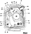
- the flushing line 116 is fixed to the inner wall 102 at the bottom ( figure 5 ).
- the cover 76 has a projection 120 in the area of the front side 92 .
- An intermediate space 122 is formed between the projection 120 and the housing 32 , in particular at the edge 74 .
- the gap 122 is also present when the lid 76 is in the closed position.
- the device 14 can be a self-propelled and self-steering floor cleaning device (a floor cleaning robot) with which the floor surface 18 can be cleaned autonomously.
- the control device 106 can control the movements of the device 14 by controlling a drive for the chassis 34 and also the cleaning units.
- the device 14 is hand-held and guided over the floor surface 18 by an operator.
- a drive for the chassis 34 can be provided.
- the operator can act on the device 14 via a handle 124 shown schematically in the drawing, which in particular comprises a gripping device.
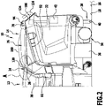
- the device 14 can be docked onto the docking station 12 in order to fill the reservoir 46 and flush the dirty liquid container 50 .
- the device 14 is moved from a non-docking position ( figure 1 ) into a docking position ( figure 2 ) emotional.
- the connection elements 22 and 90 in particular couple to one another in order to form a flow connection from the supply line 20 to the liquid line 88 .
- the opening device 24 is effective in order to move the cover 76 and thus the wall sections 80, 82 of the container walls 56 and 68 from the closed position into an open position and to hold them in this position.
- the slide-on element 26 engages in the intermediate space 122 during docking (and also in the docking position).
- a contact element 126 formed by the projection 120 contacts the slide-on surface 30 of the slide-on element 26.
- the contact element 126 slides onto the slide-on element 26.
- the cover 76 and thus the wall sections 80, 82 are subjected to an opening force for pivoting about the pivot axis 78.
- the rim 86 is lifted from the rim 74 and the rim portion 64 and the container openings 60 and 72 are exposed.
- the wall sections 80, 82 assume an open position.
- the outlet opening 114 is arranged at a distance from the container opening 60 ( figure 4 ).
- the outlet openings of the flushing line 116 are arranged at a distance from the container opening 72 in a corresponding manner. This means in particular that the outlet opening 114 or the outlet openings of the flushing line 116 are at a respective distance from the edge 62 or 74 and thus from a respective liquid level which can reach up to the edges 62 or 74 .
- the system 10 according to the invention has increased operational reliability.
- the reservoir 46 in particular can be filled with the reservoir liquid when the valve 104 is switched accordingly.
- the outlet opening 114 is spaced relative to the rim 62 and the reservoir 46 is filled via a free path running through the air and through the tank opening 60.
- the container opening 60 released in the open position of the wall section 80 allows the reservoir 46 to be vented during filling to limit the pressure.
- the pressure in the reservoir 46 is limited as a result, and this is protected against bursting, for example.
- a backup of the liquid in the supply line 20 is avoided.
- the liquid level can rise until the stored liquid emerges from the container interior 58 at the edge 62 .
- the outlet opening 114 is at a distance from the maximum liquid level. This avoids a possible risk of contamination of the liquid line 88 and the supply line 20 by particles and/or germs in the liquid in the reservoir 46.
- the tank opening 60 is an overflow opening.
- the liquid can overflow over the lower edge section 66 compared to the edge section 64 , with overflowing stored liquid being caught in the container interior 70 of the dirty liquid container 50 . This prevents overflowing storage liquid from entering the interior of the housing 32 and contaminating or damaging it.
- the valve 104 can also be switched so that the dirty liquid container 50 is flushed with flushing liquid.
- the dirty liquid contained in the container interior 70 is removed beforehand through a drain or drain opening, not shown in the drawing; for example, the dirty liquid is drained to the docking station 12 .
- the container interior 70 is exposed to the flushing liquid. If the drain or drain opening is closed or blocked, the liquid level in the interior of the container can be 70 increase. This liquid level can also rise from the reservoir 46 due to overflowing storage liquid, as mentioned.
- the container opening 72 is released for venting in order to prevent a pressure increase in the container interior 70, a backflow of the liquid into the supply line 20 and a bursting of the dirty liquid container 50.
- the reservoir opening 72 is also an overflow opening. If the liquid level in the container interior 70 reaches the edge 74, the liquid can escape from the container interior 70 and, in particular, overflow. It is advantageous that the liquid can run off the outer contour of the housing 32 and thus does not get into the interior of the housing 32 .
- the flushing line 116 When the wall section 82 is in the open position, the flushing line 116 is arranged with the outlet openings at a distance from the edge 74 . Therefore, contact of the flushing line 116 with liquid in the container interior 70 that is contaminated by any particles and/or germs can be avoided. In this case, too, contamination of the supply line 20 is prevented.
- the cover 76 and thus the wall sections 80, 82 can automatically be transferred from the open position back to the closed position.
- the lid 76 pivots again under the influence of gravity about the pivot axis 78 until the edge 86 rests on the edge 74 and the edge section 64 and both liquid containers 44, 48 close.
- the device 14 comprises a supply line 130 on the cover 76.
- the supply line 130 opens into the liquid line 88 in the receiving space 98 upstream of the valve 104.
- a connecting element 132 is arranged on the end of the supply line 130, which is designed here as a hose nipple.
- An external supply line can be connected to the connection element 132 by an operator in order to apply liquid, in particular water, to the supply line 130 .
- the liquid flows into valve 104 and from there either into one of the liquid line sections 108, 110 for filling the reservoir 46 and/or rinsing the dirty liquid tank 50. It is conceivable that the operator can use an operating device 134 of the device 14 to specify which liquid line section 108 , 110 is enabled or disabled.
- a self-locking valve arranged in the connection element 90 ensures that when the external supply line is connected and the device 14 is undocked, no liquid escapes from the liquid line 88 .
- such a filling or such a rinsing process can be carried out by connecting the external supply line to the supply line 130.
- a self-locking valve and/or a closure element 136 can also be provided on the connection element 132 so that no liquid escapes via the supply line 130 when fluid is applied to the liquid line 88 by the docking station 12 .
- figure 5 shows the closure element 136 in a state detached from the connection element 132 .
- connection element 132 is positioned to be accessible by an operator without opening cover 76 .
- the integration of the supply line 130 at least partially in the cover 76 and the arrangement of the connection element is advantageous 132 on the cover 76 in such a way that it can be opened to connect the supply line, thereby ensuring venting.
Landscapes
- Cleaning In General (AREA)
- Cleaning By Liquid Or Steam (AREA)
Description
- Die Erfindung betrifft ein Bodenbehandlungssystem, umfassend eine mobile Bodenbehandlungsvorrichtung und eine Andockstation für diese, wobei die Bodenbehandlungsvorrichtung mindestens einen Flüssigkeitsbehälter mit einer Behälterwand und einem Behälterinnenraum aufweist sowie mindestens eine Flüssigkeitsleitung zum Bereitstellen einer Flüssigkeit für den Behälterinnenraum.
- Das Bodenbehandlungssystem ist beispielsweise ein Bodenreinigungssystem, wobei die Bodenbehandlungsvorrichtung als Bodenreinigungsvorrichtung ausgestaltet ist. Diese kann mindestens ein Reinigungsaggregat zum Reinigen der Bodenfläche aufweisen, die zur Steigerung der Reinigungswirkung mit einer Reinigungsflüssigkeit (üblicherweise Wasser) aus dem mindestens einen Flüssigkeitsbehälter beaufschlagt werden kann.
- Jedoch sind auch andersartige ausgestaltete Bodenbehandlungsvorrichtungen und -systeme denkbar, bei denen eine Flüssigkeit zum Einsatz kommen kann. Zu nennen sind hier insbesondere Bodenpoliersysteme, wobei die Flüssigkeit ein Poliermittel sein kann.
- Der mindestens eine Flüssigkeitsbehälter kann daher insbesondere ein Vorratsbehälter für die Flüssigkeit sein. Bei absinkendem Pegel der Flüssigkeit im Flüssigkeitsbehälter kann die Bodenbehandlungsvorrichtung in die Andockstellung an der Andockstation überführt werden. In der Andockstellung kann dem mindestens einen Flüssigkeitsbehälter Flüssigkeit über die mindestens eine Flüssigkeitsleitung bereitgestellt werden. Beispielsweise kann ein Vorratsbehälter befüllt werden.
- Die
EP 1 762 165 A2 beschreibt ein Robotersystem mit einem Roboter und einer Befüllstation. Der Roboter kann in eine Befüllstellung an der Befüllstation verfahren und an eine Steuereinheit der Befüllstation ein Signal übertragen mit dem Ziel, einen Vorratsbehälter des Roboters mit einer Betriebsflüssigkeit zu befüllen. Auf das Signal kann die Befüllstation bei einer Ausführungsform eine Befüllleitung so ausfahren, dass diese in eine Öffnung des Vorratsbehälters eingreift. Bei einer andersartigen Ausführungsform ist die Befüllleitung im Abstand zu einer Einfüllöffnung des Vorratsbehälters angeordnet, und die Betriebsflüssigkeit wird durch die Einfüllöffnung hindurch in den Vorratsbehälter gefüllt. - Aufgabe der vorliegenden Erfindung ist es, ein Bodenbehandlungssystem der eingangs genannten Art mit einer höheren Betriebssicherheit auszubilden.
- Diese Aufgabe wird durch ein erfindungsgemäßes Bodenbehandlungssystem gelöst, umfassend eine mobile Bodenbehandlungsvorrichtung und eine Andockstation für diese, wobei die Bodenbehandlungsvorrichtung mindestens einen Flüssigkeitsbehälter mit einer Behälterwand und einem Behälterinnenraum aufweist sowie mindestens eine Flüssigkeitsleitung zum Bereitstellen einer Flüssigkeit für den Behälterinnenraum, wobei die Andockstation eine Zufuhrleitung umfasst, die in einer Andockstellung der Bodenbehandlungsvorrichtung an der Andockstation mit der mindestens einen Flüssigkeitsleitung fluidverbunden ist, wobei das Bodenbehandlungssystem eine Öffnungseinrichtung umfasst, über die ein Wandabschnitt der Behälterwand zum Freigeben mindestens einer Behälteröffnung des mindestens einen Flüssigkeitsbehälters in eine Offenstellung bewegbar ist, über welche Behälteröffnung in der Andockstellung der Bodenbehandlungsvorrichtung die Flüssigkeit aus dem Behälterinnenraum austreten kann.
- Bei dem erfindungsgemäßen Bodenbehandlungssystem ist vorgesehen, dass ein Wandabschnitt der Behälterwand eine Offenstellung einnehmen kann, wenn die Bodenbehandlungsvorrichtung die Andockstellung einnimmt. In der Offenstellung ist mindestens eine Behälteröffnung des Flüssigkeitsbehälters freigegeben. Dies gibt zum Beispiel die Möglichkeit, den Behälterinnenraum beim Beaufschlagen mit der Flüssigkeit zu entlüften. Bei zu stark ansteigendem Pegel der Flüssigkeit im Behälterinnenraum kann ferner vorgesehen sein, dass Flüssigkeit durch die Behälteröffnung hindurch aus dem Behälterinnenraum austreten kann. Auf diese Weise kann der Druck im Behälterinnenraum begrenzt und einer Stauung von Flüssigkeit und einer Rückströmung von Flüssigkeit durch die mindestens eine Flüssigkeitsleitung hindurch vorgebeugt werden. Die Zufuhrleitung der Andockstation kann gegen Eintritt von im Flüssigkeitsbehälter und darin aufgenommener Flüssigkeit möglicherweise vorhandenen Keimen oder Partikeln geschützt werden. Dies ist insbesondere dann von Bedeutung, wenn die Andockstation mit der Zufuhrleitung an ein Flüssigkeitsversorgungsnetz angeschlossen ist. Im Ergebnis weist das erfindungsgemäße Bodenbehandlungssystem daher eine höhere Betriebssicherheit auf als gattungsgemäße Bodenbehandlungssysteme.
- Der Wandabschnitt kann relativ zum mindestens einen Flüssigkeitsbehälter eine Schließstellung einnehmen, in der die mindestens eine Behälteröffnung bevorzugt überdeckt und verschlossen ist.
- Bei einer vorteilhaften Ausführungsform des Bodenbehandlungssystems ist die Bodenbehandlungsvorrichtung günstigerweise selbstfahrend und selbstlenkend. Über die als Roboter ausgestaltete Bodenbehandlungsvorrichtung kann eine autonome Bearbeitung und insbesondere Reinigung der Bodenfläche durchgeführt werden. Die Bodenbehandlungsvorrichtung kann die Andockstation selbsttätig aufsuchen, insbesondere zum Befüllen eines Vorratsbehälters mit der Flüssigkeit.
- Alternativ oder ergänzend kann vorgesehen sein, dass die Bodenbehandlungsvorrichtung handgeführt ist. Eine handgeführte Bodenbehandlungsvorrichtung kann eine Aufsitz- oder Aufstehvorrichtung sein (ride on) und/oder eine Nachlaufvorrichtung (walk behind). Eine Bedienperson kann die Bodenbehandlungsvorrichtung insbesondere zum Befüllen des Flüssigkeitsbehälters in die Andockstellung an der Andockstation überführen. Optional kann die Bodenbehandlungsvorrichtung mit einem Antrieb für ein Fahrwerk versehen sein.
- Je nach Betriebsart kann vorgesehen sein, das die Bodenbehandlungsvorrichtung selbstfahrend und selbstlenkend oder handgeführt betrieben wird.
- Die Bodenbehandlungsvorrichtung ist bei einer vorteilhaften Ausführungsform des Bodenbehandlungssystems vorzugsweise eine Bodenreinigungsvorrichtung und weist mindestens ein Reinigungsaggregat zum Reinigen einer Bodenfläche auf. Beispielsweise ist die Bodenreinigungsvorrichtung eine Scheuersaugmaschine, und das Reinigungsaggregat weist mindestens ein drehend antreibbares walzenförmiges oder tellerförmiges Reinigungswerkzeug auf. Es kann eine Schmutzaufnahmevorrichtung vorgesehen sein, um ein Gemisch aus Reinigungsflüssigkeit und Schmutz, die Schmutzflüssigkeit, in einen Schmutzflüssigkeitsbehälter der Bodenreinigungsvorrichtung zu überführen.
- Die mindestens eine Behälteröffnung ist günstigerweise eine Überlauföffnung. Wenn der Pegel der Flüssigkeit bis zum Rand der mindestens einen Behälteröffnung ansteigt, kann die Flüssigkeit durch Überlaufen aus dem Behälterinnenraum austreten.
- Es ist von Vorteil, wenn ein Rand der mindestens einen Behälteröffnung zumindest abschnittsweise entlang einer Außenkontur der Bodenbehandlungsvorrichtung verläuft, die von einem Gehäuse der Bodenbehandlungsvorrichtung gebildet ist, und wenn die Flüssigkeit außen am Gehäuse ausfließen kann. Austretende Flüssigkeit kann außenseitig am Gehäuse ablaufen, und ein Ausfließen von Flüssigkeit ins Innere der Bodenbehandlungsvorrichtung kann vermieden werden. Etwaige Verschmutzungen oder Beschädigungen durch ausfließende Flüssigkeit lassen sich dadurch vermeiden.
- Insbesondere ist ein tiefster Abschnitt des Randes günstigerweise an der Au-ßenkontur der Bodenbehandlungsvorrichtung angeordnet.
- Vorzugsweise ist der Wandabschnitt in die Offenstellung mittels der Öffnungseinrichtung durch Bewegen der Bodenbehandlungsvorrichtung von einer Nichtandockstellung in die Andockstellung überführbar. Beim Bewegen der Bodenbehandlungsvorrichtung an die Andockstation zum Einnehmen der Andockstellung kann der Wandabschnitt durch die Öffnungseinrichtung selbsttätig und vorzugsweise ohne Antrieb in die Offenstellung überführt werden. Dadurch ist sichergestellt, dass die mindestens eine Behälteröffnung bereits beim Andocken der Bodenbehandlungsvorrichtung an die Andockstation freigegeben ist.
- Die Öffnungseinrichtung kann auf unterschiedliche Weise ausgestaltet sein. Beispielsweise ist eine mechanische, elektrische, hydraulische, pneumatische und/oder magnetische Öffnungseinrichtung vorgesehen. Die Öffnungseinrichtung kann aktiv ausgestaltet sein und mindestens einen Antrieb oder Aktor umfassen, um den Wandabschnitt zu bewegen. Der Antrieb oder Aktor kann direkt oder indirekt am Wandabschnitt angreifen. Es kann eine Rückstelleinrichtung vorgesehen sein, um den Wandabschnitt von der Offenstellung wieder in eine Schließstellung zu überführen. Die Einnahme der Andockstellung an der Andockstation kann mittels mindestens einer Sensoreinrichtung erfasst werden.
- Die Öffnungseinrichtung kann an der Bodenbehandlungsvorrichtung oder an der Andockstation angeordnet oder von dieser umfasst sein. Denkbar ist auch eine Öffnungseinrichtung, deren Komponenten sowohl an der Andockstation als auch an der Bodenbehandlungsvorrichtung angeordnet oder von diesen umfasst sind.
- Bei einer vorteilhaften Ausführungsform des Bodenbehandlungssystems umfasst die Öffnungseinrichtung ein Anschlag- oder Aufgleitelement an der Station und ein Kontaktelement am Wandabschnitt, das beim Andocken der Bodenbehandlungsvorrichtung an die Station mit dem Anschlag- oder Aufgleitelement koppelt. Auf diese Weise kann der Wandabschnitt beim Bewegen von einer Nichtandockstellung in die Andockstellung, wie vorstehend erläutert, ohne Antrieb in die Offenstellung überführt werden. Bereits beim Andocken ist dadurch sichergestellt, dass die mindestens eine Behälteröffnung freigegeben ist. Ein Aufgleitelement kann eine Aufgleitfläche aufweisen, die im Winkel zu einer Andockrichtung der Bodenbehandlungsvorrichtung an die Andockstation ausgerichtet ist.
- Günstigerweise ist das Aufgleitelement keilförmig ausgestaltet. Beispielsweise kann das Aufgleitelement in einen Zwischenraum zwischen dem Wandabschnitt und einem Gehäuseabschnitt der Bodenbehandlungsvorrichtung eingreifen. Beim Kontaktieren des Aufgleitelementes kann das Kontaktelement mit einer den Wandabschnitt öffnenden Kraft beaufschlagt werden.
- Alternativ oder ergänzend ist es von Vorteil, wenn das Aufgleitelement den Wandabschnitt zum Überführen in die oder zum Halten in der Offenstellung untergreift. Eine derartige Ausgestaltung ist insbesondere dann von Vorteil, wenn der Wandabschnitt von einer Deckenwand und insbesondere von einem Deckel des mindestens einen Flüssigkeitsbehälters gebildet oder umfasst ist.
- Vorteilhafterweise ist der Wandabschnitt in der Andockstellung der Bodenbehandlungsvorrichtung mittels der Öffnungseinrichtung in der Offenstellung gehalten.
- Vorteilhafterweise ist der Wandabschnitt auch dann in der Andockstellung der Bodenbehandlungsvorrichtung in der Offenstellung gehalten, wenn eine Fluidverbindung durch die Zufuhrleitung und die mindestens eine Flüssigkeitsleitung mittels mindestens eines Ventils des Bodenbehandlungssystems unterbunden ist und der mindestens eine Flüssigkeitsbehälter nicht mit der Flüssigkeit beaufschlagt ist. Auch dann, wenn die Bodenbehandlungsvorrichtung an die Andockstation angedockt ist, über die mindestens eine Flüssigkeitsleitung jedoch keine Flüssigkeit für den mindestens einen Flüssigkeitsbehälter bereitgestellt wird, kann der Wandabschnitt zum Freigeben der mindestens einen Behälteröffnung die Offenstellung einnehmen. Eine Entlüftung des Behälterinnenraums und ein Austreten von Flüssigkeit ist weiterhin möglich, um die Betriebssicherheit des Bodenbehandlungssystems zu steigern.
- In die mindestens eine Flüssigkeitsleitung und/oder in die Zufuhrleitung ist vorzugsweise mindestens ein Ventil geschaltet, wobei das mindestens eine Ventil zum Freigeben und/oder Sperren der mindestens einen Flüssigkeitsleitung und/oder der Zufuhrleitung betätigbar ist.
- Das mindestens eine Ventil ist vorzugsweise von einer Steuereinrichtung des Bodenbehandlungssystems freigebbar oder betätigbar. Die Steuereinrichtung kann in der Bodenbehandlungsvorrichtung oder in der Andockstation angeordnet sein.
- Es kann vorgesehen sein, dass das mindestens eine Ventil durch Bewegen der Bodenbehandlungsvorrichtung in die Andockstellung zum Freigeben betätigbar ist. Umgekehrt kann vorgesehen sein, dass das mindestens eine Ventil durch Bewegen der Bodenbehandlungsvorrichtung aus der Andockstellung in eine Nichtandockstellung zum Sperren betätigbar ist.
- Die Behälterwand kann eine Deckenwand umfassen, die den Wandabschnitt umfasst oder ausbildet.
- Bei einer vorteilhaften Ausführungsform weist die Bodenbehandlungsvorrichtung einen Deckel des mindestens einen Flüssigkeitsbehälters auf, der den Wandabschnitt umfasst oder ausbildet. Der Deckel kann daher als Ganzes oder teilweise ein Abschnitt der Behälterwand sein. Die vorstehend genannte Deckenwand kann durch den Deckel ausgebildet sein.
- Günstig ist es, wenn der Deckel mittels der Öffnungseinrichtung von einem Rand der mindestens einen Behälteröffnung anhebbar ist, wobei die Behälteröffnung freigegeben werden kann. In entsprechender Weise ist es von Vorteil, wenn der Deckel in einer Schließstellung zumindest bereichsweise am Rand der mindestens einen Behälteröffnung anliegt und den Behälterinnenraum überdeckt.
- Der Wandabschnitt, insbesondere der Deckel, kann verschwenkbar und/oder verschieblich gelagert sein zum Aufschwenken bzw. Aufschieben mittels der Öffnungseinrichtung. Eine Lagerung des Wandabschnittes erfolgt bevorzugt an einem Gehäuse der Bodenbehandlungsvorrichtung.
- Bei einer vorteilhaften Ausführungsform ist der Wandabschnitt von einem Deckel gebildet oder umfasst, der mit einem Kontaktelement ein Aufgleitelement der Öffnungseinrichtung kontaktieren kann, wenn die Bodenbehandlungsvorrichtung in die Andockstellung verfährt. Der Deckel kann durch Aufgleiten an der Andockstation verschwenkt und dadurch die mindestens eine Behälteröffnung freigegeben werden.
- Günstig ist es, wenn der Wandabschnitt, insbesondere der Deckel, unter Schwerkrafteinfluss von der Offenstellung in eine Schließstellung überführbar ist, in der die mindestens eine Behälteröffnung überdeckt ist. Das Bodenbehandlungssystem weist dadurch eine einfache konstruktive Ausgestaltung auf. Ist der Wandabschnitt nicht mittels der Öffnungseinrichtung in der Offenstellung gehalten, kehrt er selbsttätig wieder in die Schließstellung zurück, beispielsweise beim Abdocken der Bodenbehandlungsvorrichtung von der Andockstation.
- Alternativ oder ergänzend kann vorgesehen sein, dass der Wandabschnitt ausgehend von der Offenstellung mittels einer Rückstelleinrichtung in eine Schließstellung überführbar ist.
- Als günstig erweist es sich bei einer konstruktiv einfachen Ausgestaltung des Bodenbehandlungssystems, wenn die mindestens eine Flüssigkeitsleitung am Wandabschnitt festgelegt ist.
- Beispielsweise ist vorgesehen, dass die mindestens eine Flüssigkeitsleitung zumindest abschnittsweise durch den Wandabschnitt hindurch verläuft oder von diesem gebildet ist. Der Wandabschnitt, beispielsweise der Deckel, bildet zum Beispiel einen Hohlkörper, in dem die mindestens eine Flüssigkeitsleitung abschnittsweise verläuft.
- Von Vorteil ist es, wenn die mindestens eine Flüssigkeitsleitung mindestens eine Austrittsöffnung für Flüssigkeit aufweist und wenn die mindestens eine Austrittsöffnung in der Offenstellung des Wandabschnittes oberhalb eines Randes der mindestens einen Behälteröffnung positioniert ist, bezogen auf eine Höhenrichtung. Auf diese Weise kann die mindestens eine Austrittsöffnung in der Offenstellung des Wandabschnittes einen Abstand zum Rand und zur mindestens einen Behälteröffnung aufweisen. Steigt der Pegel der Flüssigkeit im Behälterinnenraum bis zum Rand, ist auf diese Weise sichergestellt, dass die Flüssigkeit nicht bis an die mindestens eine Austrittsöffnung gelangt. Die Betriebssicherheit der Bodenbehandlungsvorrichtung wird dadurch erhöht, denn etwaige Partikel oder Keime können nicht an die mindestens eine Flüssigkeitsleitung gelangen und widrigstenfalls zu einer Kontamination der Zufuhrleitung in der Andockstation führen.
- Positions- und Orientierungsangaben wie beispielsweise "oberhalb", "unterhalb" oder dergleichen sind auf eine Gebrauchsstellung des Bodenbehandlungssystems auf einer Aufstellfläche bezogen aufzufassen. Die mindestens eine Austrittsöffnung ist daher in Höhenrichtung ausgehend von der Aufstellfläche oberhalb des Randes der mindestens einen Behälteröffnung positioniert, jedoch nicht notwendigerweise direkt oberhalb des Randes, aber oberhalb der Behälteröffnung.
- Die mindestens eine Austrittsöffnung ist bevorzugt, bezogen auf eine Höhenrichtung, oberhalb einer tiefsten Position des Randes der mindestens einen Behälteröffnung positioniert, wenn der Wandabschnitt die Offenstellung einnimmt.
- Bei einer vorteilhaften Ausführungsform des Bodenbehandlungssystems ist als Flüssigkeitsbehälter ein Vorratsbehälter für eine Verbrauchsflüssigkeit vorgesehen, und als Flüssigkeitsleitung ist eine Befüllleitung zum Befüllen des Vorratsbehälters mit der Verbrauchsflüssigkeit vorgesehen. Die Verbrauchsflüssigkeit kann im Fall eines Bodenreinigungssystems zum Beispiel eine Reinigungsflüssigkeit sein, insbesondere Wasser oder eine Reinigungschemikalie. Die Bodenfläche kann mit der Reinigungsflüssigkeit beaufschlagbar sein und mittels mindestens eines Reinigungsaggregates abgereinigt werden. Übersteigt der Pegel der Verbrauchsflüssigkeit beim Befüllen einen Schwellenwertpegel, kann die Verbrauchsflüssigkeit über die Behälteröffnung aus dem Behälterinnenraum austreten.
- Alternativ oder ergänzend kann bei einer vorteilhaften Ausführungsform des Bodenbehandlungssystems vorgesehen sein, dass als Flüssigkeitsbehälter ein Schmutzflüssigkeitsbehälter zur Aufnahme einer Schmutzflüssigkeit vorgesehen ist und dass als Flüssigkeitsleitung eine Spülleitung zum Spülen des Schmutzflüssigkeitsbehälters vorgesehen ist. Beispielsweise kann bei einer Bodenreinigungsvorrichtung ein Schmutzflüssigkeitsbehälter vorgesehen sein, in den die Schmutzflüssigkeit nach Aufnehmen von der Bodenfläche überführt wird. Über die Spülleitung kann die Spülflüssigkeit, beispielsweise durch eine Spüleinrichtung der Bodenbehandlungsvorrichtung, zum Spülen des Schmutzflüssigkeitsbehälters verwendet werden. Es kann beispielsweise vorkommen, dass eine Auslass- oder Ablassöffnung des Schmutzflüssigkeitsbehälters geschlossen oder blockiert ist, so dass beim Beaufschlagen des Behälterinnenraums mit Spülflüssigkeit deren Pegel im Schmutzflüssigkeitsbehälter ansteigt. Über die mindestens eine Behälteröffnung kann die Schmutzflüssigkeit aus dem Behälterinnenraum austreten.
- Die vorstehenden Erläuterungen zeigen, dass die Bodenbehandlungsvorrichtung mehr als einen Flüssigkeitsbehälter umfassen kann.
- Bei einer vorteilhaften Ausführungsform ist vorgesehen, dass die mindestens eine Flüssigkeitsleitung an einem schaltbaren Ventil in einen ersten Flüssigkeitsleitungsabschnitt und in einen zweiten Flüssigkeitsleitungsabschnitt verzweigt, über die einem jeweiligen Flüssigkeitsbehälter Flüssigkeit bereitstellbar ist. Das Ventil kann zum Beispiel von der bereits genannten Steuereinrichtung des Bodenbehandlungssystems angesteuert werden. Insbesondere kann wahlweise ein Vorratsbehälter mit einer Verbrauchsflüssigkeit befüllt oder ein Schmutzflüssigkeitsbehälter mit einer Spülflüssigkeit gespült werden.
- Alternativ kann vorgesehen sein, dass die mindestens eine Flüssigkeitsleitung in zwei Flüssigkeitsleitungsabschnitte verzweigt, in die jeweils ein Ventil geschaltet ist.
- Ferner kann vorgesehen sein, dass zwei getrennte Flüssigkeitsleitungen zum Beaufschlagen eines jeweiligen Flüssigkeitsbehälters mit Flüssigkeit vorgesehen sind.
- Der Wandabschnitt gibt vorzugsweise in der Offenstellung die jeweilige Behälteröffnung der Flüssigkeitsbehälter frei. Ein Wandabschnitt, insbesondere gebildet oder umfasst von einem Deckel, kann als Bestandteil einer jeweiligen Behälterwand für mehr als einen Flüssigkeitsbehälter vorgesehen sein. Durch Überführen nur eines Wandabschnittes können Behälteröffnungen von mehr als einem Flüssigkeitsbehälter freigegeben werden.
- Die Behälteröffnungen sind vorzugsweise seitlich nebeneinander positioniert, wobei der Wandabschnitt günstigerweise in einer Schließstellung an einem beide Behälteröffnungen einfassenden Rand anliegt. In einer Schließstellung kann der Wandabschnitt, insbesondere der Deckel, beide Behälteröffnungen überdecken.
- Es kann vorgesehen sein, dass die Behälteröffnungen von zwei Flüssigkeitsbehältern einen gemeinsamen Randabschnitt aufweisen. Dieser Randabschnitt kann der tiefste Randabschnitt eines Randes zumindest einer Behälteröffnung sein. Dies gibt zum Beispiel die Möglichkeit, dass Flüssigkeit aus einem ersten Behälterinnenraum über den tiefsten Randabschnitt in einen weiteren Behälterinnenraum austreten und insbesondere überlaufen kann.
- Die Bodenbehandlungsvorrichtung kann mindestens einen Schwimmkörper aufweisen, der im Behälterinnenraum eines Flüssigkeitsbehälters positioniert ist und mit einem in die mindestens eine Flüssigkeitsleitung geschalteten Ventil gekoppelt ist, um dieses bei einem vorgebbaren Schwellenwertpegel der Flüssigkeit im Flüssigkeitsbehälter zu verschließen. Dies erlaubt eine weitere Steigerung der Betriebssicherheit. Über den Schwimmkörper kann das Ventil geschlossen und eine weitere Beaufschlagung des Behälterinnenraums mit der Flüssigkeit verhindert werden.
- Vorteilhafterweise liegt der Schwellenwertpegel unterhalb eines Randes der Behälteröffnung. Dadurch lässt sich zum Beispiel sicherstellen, dass ein Austreten und insbesondere Überlaufen von Flüssigkeit über die mindestens eine Behälteröffnung nur dann auftritt, wenn eine Störung der Schwimmkörper-Ventil-Funktion vorliegt.
- Günstig ist es, wenn die Bodenbehandlungsvorrichtung eine Zufuhrleitung mit daran angeordnetem Anschlusselement umfasst, die in die mindestens eine Flüssigkeitsleitung mündet und an welches Anschlusselement manuell eine externe Versorgungsleitung zum Bereitstellen von Flüssigkeit für den mindestens einen Flüssigkeitsbehälter anschließbar ist. Dadurch ist das Bodenbehandlungssystem vielseitiger einsetzbar. An das zusätzliche Anschlusselement kann eine Bedienperson eine separate, externe Versorgungsleitung anschlie-ßen. Dies erlaubt es, den Flüssigkeitsbehälter unabhängig von der Andockstation mit Flüssigkeit zu beaufschlagen. Beispielsweise kann der Vorratsbehälter befüllt und/oder der Schmutzflüssigkeitsbehälter gespült werden. Die Zufuhrleitung und das Anschlusselement sind vorzugsweise am Wandabschnitt und insbesondere am Deckel angeordnet.
- Die nachfolgende Beschreibung bevorzugter Ausführungsformen der Erfindung dient im Zusammenhang mit der Zeichnung der näheren Erläuterung der Erfindung. Es zeigen:
- Figur 1:
- eine Seitenansicht eines erfindungsgemäßen Bodenbehandlungssystems mit einer Andockstation und einer Bodenbehandlungsvorrichtung, die eine Nichtandockstellung einnimmt;
- Figur 2:
- das Bodenbehandlungssystem aus
Figur 1 , wobei die Bodenbehandlungsvorrichtung eine Andockstellung einnimmt; - Figur 3:
- eine perspektivische (Teil-)Darstellung der Bodenbehandlungsvorrichtung aus
Figur 1 mit einem eine Offenstellung einnehmenden Deckel; - Figur 4:
- eine vergrößerte Darstellung, teilweise schematisch, von Detail A in
Figur 2 ; und - Figur 5:
- eine Ansicht von unten, teilweise schematisch, des Deckels der Bodenbehandlungsvorrichtung aus
Figur 1 . -
Figur 1 zeigt eine bevorzugte Ausführungsform eines erfindungsgemäßen Bodenbehandlungssystems, das mit dem Bezugszeichen 10 belegt ist und nachfolgend vereinfachend als System 10 bezeichnet wird. Das System 10 umfasst eine Andockstation 12 und eine mobile Bodenbehandlungsvorrichtung 14, nachfolgend vereinfachend als Vorrichtung 14 bezeichnet. Das System 10 ist in einer Gebrauchsstellung auf einer Aufstellfläche 16 positioniert, die gleichzeitig eine zu reinigende Bodenfläche 18 bildet. - Die Andockstation 12 umfasst eine Zufuhrleitung 20, die in nicht dargestellter Weise an ein Versorgungsnetz angeschlossen ist. Dabei handelt es sich insbesondere um ein Wasserversorgungsnetz, um die Zufuhrleitung 20 mit Wasser zu beaufschlagen. Wasser ist wie nachfolgend erläutert zugleich eine Vorratsflüssigkeit und eine Spülflüssigkeit für die Vorrichtung 14. Ausgangsseitig ist an der Zufuhrleitung 20 ein Anschlusselement 22 angeordnet.
- Weiter umfasst die Andockstation 12 eine Öffnungseinrichtung 24. Die Öffnungseinrichtung 24 dient wie nachfolgend erläutert zum Überführen eines Deckels der Vorrichtung 14 in eine Offenstellung.
- Die Öffnungseinrichtung 24 weist ein Aufgleitelement 26 auf, das beispielsweise an einem Gehäuse 28 der Andockstation 12 angeordnet oder von diesem umfasst ist. Das Aufgleitelement 26 ist durch einen obenseitig am Gehäuse 28 gebildeten Vorsprung gebildet. Das Aufgleitelement 26 ist keilförmig ausgestaltet und umfasst eine Aufgleitfläche 30. Die Aufgleitfläche 30 ist vorliegend im Winkel zu einer von der Aufstellfläche 16 definierten Ebene ausgerichtet. Diese Ebene ist bei horizontal angenommener Aufstellfläche 16 eine Horizontalebene, so dass die Aufgleitfläche 30 im Winkel zur Horizontalen ausgerichtet ist.
- Positions- und Orientierungsangaben wie "oberhalb", "unterhalb" oder dergleichen sind auf die Gebrauchsstellung des Systems 10 auf der Aufstellfläche 16 bezogen aufzufassen.
- Die Vorrichtung 14 ist als Bodenreinigungsvorrichtung ausgestaltet und umfasst ein Gehäuse 32, an dessen Unterseite ein Fahrwerk 34 zum Verfahren auf der Bodenfläche 18 angeordnet ist. Am Gehäuse 32 ist ferner ein Reinigungsaggregat 36 angeordnet, um die Bodenfläche 18 zu reinigen.
- Die Vorrichtung 14 ist eine Scheuersaugmaschine, so dass das Reinigungsaggregat 36 mindestens ein in der Zeichnung nicht gezeigtes drehend antreibbares bürstenförmiges oder tellerförmiges Reinigungswerkzeug aufweist. Ein weiteres Reinigungsaggregat ist an der Vorrichtung 14 in Gestalt einer Schmutzaufnahmevorrichtung 38 vorgesehen (in
Figur 3 nicht dargestellt). Die Schmutzaufnahmevorrichtung 38 weist eine in denFiguren 1 und2 dargestellte Saugleiste 40 auf sowie ein Saugaggregat 42 zum Beaufschlagen der Saugleiste 40 mit Unterdruck. - Die Vorrichtung 14 umfasst einen ersten Flüssigkeitsbehälter 44, der ein Vorratsbehälter 46 für eine Vorrats- und insbesondere Reinigungsflüssigkeit ist, speziell Wasser. Weiter umfasst die Vorrichtung 14 einen zweiten Flüssigkeitsbehälter 48 zum Aufnehmen von Schmutzflüssigkeit, der über eine Spülflüssigkeit, insbesondere Wasser, gespült werden kann. Der zweite Flüssigkeitsbehälter 48 ist daher ein Schmutzflüssigkeitsbehälter 50.
- Das Gehäuse 32 der Vorrichtung 14 umfasst ein sogenanntes Behälter-im-Behälter-Konzept, bei dem der Schmutzflüssigkeitsbehälter 50 von dem ihn umgebenden Vorratsbehälter 46 eingefasst ist. Dementsprechend ist das Gehäuse 32 doppelwandig ausgestaltet mit einer Außenwand 52 und einer Innenwand 54.
- Der Vorratsbehälter 46 ist durch eine Behälterwand 56 begrenzt, die u.a. die Außenwand 52, die Innenwand 54 und eine in der Zeichnung nicht gezeigte Bodenwand umfasst. Die Behälterwand 56 begrenzt einen Behälterinnenraum 58. Obenseitig am Vorratsbehälter 46 ist eine Behälteröffnung 60 vorgesehen, die einen Rand 62 aufweist. Der Rand 62 umfasst einen Randabschnitt 64 entlang der Außenkontur des Gehäuses 32 und einen Randabschnitt 66, der der Außenkontur des Gehäuses 32 abgewandt ist.
- Der Schmutzflüssigkeitsbehälter 50 umfasst eine Behälterwand 68, die die Innenwand 54 und eine in der Zeichnung nicht gezeigte Bodenwand umfasst. Die Behälterwand 68 fasst einen Behälterinnenraum 70 ein. Obenseitig weist der Schmutzflüssigkeitsbehälter 50 eine Behälteröffnung 72 auf, die von einem Rand 74 eingefasst ist. Der Rand 74 verläuft größtenteils entlang der Außenkontur des Gehäuses 32. Ein Abschnitt des Randes 74 ist der Randabschnitt 66 des Randes 62. Die Behälteröffnung 60 und die Behälteröffnung 72 sind dadurch über den Randabschnitt 66 voneinander getrennt.
- Im Betrieb der Vorrichtung 14 kann die Reinigungsflüssigkeit im Vorratsbehälter 46, optional und vorzugsweise unter Beimischung einer Reinigungschemikalie, auf die Bodenfläche 18 aufgebracht werden. Schmutz kann mittels des Reinigungsaggregates 36 von der Bodenfläche 18 abgelöst werden. Die Schmutzflüssigkeit kann über die Schmutzaufnahmevorrichtung 38 von der Bodenfläche 18 aufgenommen und im Schmutzflüssigkeitsbehälter 50 abgeschieden werden.
- Die Vorrichtung 14 weist, als Bestandteil des Gehäuses 32, eine Abdeckung für die Flüssigkeitsbehälter 44, 48 auf. Die Abdeckung ist als Deckel 76 ausgestaltet. Der Deckel 76 ist vorliegend um eine Schwenkachse 78 schwenkbar am Gehäuse 32 im Übrigen gehalten. Durch Verschwenken kann der Deckel 76 auf- und zugeklappt werden.
- Der Deckel 76 bildet vorliegend eine Deckenwand sowohl für den Vorratsbehälter 46 als auch für den Schmutzflüssigkeitsbehälter 50. Dementsprechend bildet der Deckel 76 einen Bestandteil der Behälterwand 56 des Vorratsbehälters 46 in Form eines Wandabschnittes 80. Weiter bildet der Deckel 76 einen Bestandteil der Behälterwand 68 des Schmutzflüssigkeitsbehälters 50 in Form eines Wandabschnittes 82.
- An einer Unterseite weist der Deckel 76 einen umlaufenden Rand 86 auf. Der Rand 86 ist weitgehend korrespondierend zum Rand 74 der Behälteröffnung 72 ausgebildet.
- In einer Schließstellung des Deckels 72 liegt der Rand 86 am Rand 74 und am Randabschnitt 64 an und insbesondere auf diesen auf (
Figur 1 ). Der Deckel 76 überdeckt als Wandabschnitt 80 die Behälteröffnung 60 und als Wandabschnitt 82 die Behälteröffnung 72. Sowohl der Vorratsbehälter 46 als auch der Schmutzflüssigkeitsbehälter 50 sind geschlossen. - Durch Verschwenken um die Schwenkachse 78 kann der Deckel 76 in eine Offenstellung überführt werden (
Figuren 2 und4 bzw.Figur 3 mit unterschiedlichen Offenstellungen). In der Offenstellung ist der Rand 86 vom Rand 74 und vom Randabschnitt 64 angehoben, und die Behälteröffnungen 60 und 72 sind freigegeben. Besonders gut zu erkennen ist dies inFigur 3 , jedoch erfolgt eine Freigabe der Behälteröffnungen 60 und 72 auch bei geringerem Schwenkwinkel des Deckels 76 in der in denFiguren 2 und4 dargestellten Offenstellung des Deckels 76. - Die Vorrichtung 14 umfasst eine Flüssigkeitsleitung 88 mit einem eingangsseitig angeordneten Anschlusselement 90. Das Anschlusselement 90 ist an einer Vorderseite 92 der Vorrichtung 14 angeordnet, und die Flüssigkeitsleitung 88 erstreckt sich mit einem in der Zeichnung nicht dargestellten Leitungsabschnitt durch das Gehäuse 32 bis zu einem die Schwenkachse 78 definierenden Gelenk 94 zur schwenkbaren Lagerung des Deckels 76. Die Flüssigkeitsleitung 88 ist durch das Gelenk 94 hindurchgeführt.
- "Vorderseite" bezieht sich auf eine Längs- oder Hauptbewegungsrichtung der Vorrichtung 14. In der Andockstellung der Vorrichtung 14 ist die Vorderseite 92 einer Stirnseite der Andockstation 12 zugewandt.
- Der Deckel 76 bildet einen Hohlkörper 96 mit einem Aufnahmeraum 98 zwischen einer Außenwand 100 an der Oberseite der Vorrichtung 14 und einer Innenwand 102.
- Wie insbesondere aus den
Figuren 4 und5 hervorgeht, ist die Flüssigkeitsleitung 88 strömungsabwärts des Gelenkes 94 im Aufnahmeraum 98 aufgenommen. Der Aufnahmeraum 98 nimmt ferner ein ansteuerbares Ventil 104 auf, das von einer Steuereinrichtung 106 der Vorrichtung 14 betätigbar ist (Figuren 1 und2 ). An dem Ventil 104 verzweigt die Flüssigkeitsleitung 88 in einen ersten Flüssigkeitsleitungsabschnitt 108 und einen zweiten Flüssigkeitsleitungsabschnitt 110. Unter Ansteuerung durch die Steuereinrichtung 106 kann das Ventil 104 so geschaltet werden, dass Flüssigkeit wahlweise einem, oder beiden, der Flüssigkeitsleitungsabschnitte 108, 110 zugeführt wird. Es können zwei einzelne Ventile durch das Ventil 104 gebildet werden. - Über den Flüssigkeitsleitungsabschnitt 108 ist eine Befüllleitung 112 zum Befüllen des Vorratsbehälters 46 gebildet, die eine Austrittsöffnung 114 an der Innenwand 102 aufweist (
Figuren 4 und5 ). - Über den Flüssigkeitsleitungsabschnitt 110 ist eine Spülleitung 116 zum Spülen des Schmutzflüssigkeitsbehälters 50 gebildet. Die Spülleitung 116 umfasst eine Ringleitung 118 mit einer Mehrzahl von nicht gezeigten Austrittsöffnungen für die Spülflüssigkeit. Die Spülleitung 116 ist untenseitig an der Innenwand 102 festgelegt (
Figur 5 ). - Der Deckel 76 weist im Bereich der Vorderseite 92 einen Vorsprung 120 auf. Zwischen dem Vorsprung 120 und dem Gehäuse 32 ist, insbesondere am Rand 74, ein Zwischenraum 122 gebildet. Der Zwischenraum 122 ist auch bei dem die Schließstellung einnehmenden Deckel 76 vorhanden.
- Die Vorrichtung 14 kann eine selbstfahrende und selbstlenkende Bodenreinigungsvorrichtung sein (ein Bodenreinigungsroboter), mit der eine autonome Reinigung der Bodenfläche 18 durchgeführt werden kann. Die Steuereinrichtung 106 kann die Bewegungen der Vorrichtung 14 unter Ansteuerung eines Antriebes für das Fahrwerk 34 und auch die Reinigungsaggregate ansteuern.
- Alternativ oder ergänzend kann vorgesehen sein, dass die Vorrichtung 14 handgeführt ist und von einer Bedienperson über die Bodenfläche 18 geführt wird. Es kann ein Antrieb für das Fahrwerk 34 vorgesehen sein. Die Bedienperson kann über eine in der Zeichnung schematisch dargestellte Handhabe 124, die insbesondere eine Griffeinrichtung umfasst, auf die Vorrichtung 14 einwirken.
- Zum Befüllen des Vorratsbehälters 46 und Spülen des Schmutzflüssigkeitsbehälters 50 kann die Vorrichtung 14 an die Andockstation 12 angedockt werden. Selbsttätig oder unter Führung durch die Bedienperson wird die Vorrichtung 14 dabei von einer Nichtandockstellung (
Figur 1 ) in eine Andockstellung (Figur 2 ) bewegt. In der Andockstellung koppeln insbesondere die Anschlusselemente 22 und 90 miteinander, um eine Strömungsverbindung von der Zufuhrleitung 20 zur Flüssigkeitsleitung 88 zu bilden. - Beim Andocken und bei Einnahme der Andockstellung ist die Öffnungseinrichtung 24 wirksam, um den Deckel 76 und damit die Wandabschnitte 80, 82 der Behälterwände 56 bzw. 68 von der Schließstellung in eine Offenstellung zu überführen und in dieser zu halten. Dabei greift das Aufgleitelement 26 beim Andocken (und auch in der Andockstellung) in den Zwischenraum 122 ein. Ein vom Vorsprung 120 gebildetes Kontaktelement 126 kontaktiert die Aufgleitfläche 30 des Aufgleitelementes 26. Beim Andocken der Vorrichtung 14 in einer Andockrichtung 128, vorliegend parallel zur Aufstellfläche 16 und damit horizontal, gleitet das Kontaktelement 126 auf dem Aufgleitelement 26 auf. Der Deckel 76 und damit die Wandabschnitte 80, 82 werden mit einer Öffnungskraft zum Verschwenken um die Schwenkachse 78 beaufschlagt. Der Rand 86 wird vom Rand 74 und vom Randabschnitt 64 angehoben, und die Behälteröffnungen 60 und 72 sind freigegeben. Die Wandabschnitte 80, 82 nehmen eine Offenstellung ein.
- In der Offenstellung der Wandabschnitte 80, 82 ist die Austrittsöffnung 114 im Abstand zur Behälteröffnung 60 angeordnet (
Figur 4 ). In entsprechender Weise sind die Austrittsöffnungen der Spülleitung 116 im Abstand zur Behälteröffnung 72 angeordnet. Dies bedeutet jeweils insbesondere, dass die Austrittsöffnung 114 bzw. die Austrittsöffnungen der Spülleitung 116 einen jeweiligen Abstand zum Rand 62 bzw. 74 aufweisen und damit zu einem jeweiligen Flüssigkeitspegel, der bis zu den Rändern 62 bzw. 74 reichen kann. - Das erfindungsgemäße System 10 weist eine erhöhte Betriebssicherheit auf.
- Nimmt die Vorrichtung 14 die Andockstellung ein, kann bei entsprechend geschaltetem Ventil 104 insbesondere der Vorratsbehälter 46 mit der Vorratsflüssigkeit befüllt werden. Es besteht eine Strömungsverbindung durch die Zufuhrleitung 20 und die Flüssigkeitsleitung 88 als Befüllleitung 112. Die Austrittsöffnung 114 ist relativ zum Rand 62 beabstandet, und der Vorratsbehälter 46 wird über eine freie, durch die Luft verlaufende Wegstrecke und durch die Behälteröffnung 60 hindurch befüllt.
- Die in der Offenstellung des Wandabschnittes 80 freigegebene Behälteröffnung 60 erlaubt es, den Vorratsbehälter 46 beim Befüllen zur Druckbegrenzung zu entlüften. Der Druck im Vorratsbehälter 46 ist dadurch begrenzt, und dieser ist beispielsweise gegen Bersten geschützt. Ein Rückstau der Flüssigkeit in die Zufuhrleitung 20 wird vermieden. Der Flüssigkeitspegel kann so lange ansteigen, bis die Vorratsflüssigkeit am Rand 62 aus dem Behälterinnenraum 58 austritt. Die Austrittsöffnung 114 ist dabei vom maximalen Flüssigkeitspegel beabstandet. Dies vermeidet eine mögliche Gefahr der Kontamination der Flüssigkeitsleitung 88 und der Zufuhrleitung 20 durch Partikel und/oder Keime in der Flüssigkeit im Vorratsbehälter 46.
- Die Behälteröffnung 60 ist eine Überlauföffnung. Die Flüssigkeit kann über den gegenüber dem Randabschnitt 64 tieferliegenden Randabschnitt 66 überlaufen, wobei überlaufende Vorratsflüssigkeit im Behälterinnenraum 70 des Schmutzflüssigkeitsbehälters 50 aufgefangen wird. Dadurch wird vermieden, dass überlaufende Vorratsflüssigkeit ins Innere des Gehäuses 32 gelangt und dieses verschmutzt oder beschädigt.
- Das Ventil 104 kann ferner so geschaltet werden, dass der Schmutzflüssigkeitsbehälter 50 mit Spülflüssigkeit gespült wird. Vorzugsweise wird im Behälterinnenraum 70 aufgenommene Schmutzflüssigkeit zuvor durch eine in der Zeichnung nicht dargestellte Ablass- oder Ablauföffnung entfernt, beispielsweise wird die Schmutzflüssigkeit an die Andockstation 12 abgelassen.
- Beim Spülen des Schmutzflüssigkeitsbehälters 50 wird der Behälterinnenraum 70 mit der Spülflüssigkeit beaufschlagt. Bei geschlossener oder blockierter Ablass- oder Ablauföffnung kann der Flüssigkeitspegel im Behälterinnenraum 70 ansteigen. Dieser Flüssigkeitspegel kann auch durch überlaufende Vorratsflüssigkeit, wie erwähnt, aus dem Vorratsbehälter 46 ansteigen.
- In der Offenstellung des Wandabschnittes 82 ist die Behälteröffnung 72 zur Entlüftung freigegeben, um einen Druckanstieg im Behälterinnenraum 70, einen Rückstau der Flüssigkeit in die Zufuhrleitung 20 und ein Bersten des Schmutzflüssigkeitsbehälters 50 zu vermeiden.
- Die Behälteröffnung 72 ist ebenfalls eine Überlauföffnung. Gelangt der Flüssigkeitspegel im Behälterinnenraum 70 bis zum Rand 74, kann die Flüssigkeit aus dem Behälterinnenraum 70 austreten und insbesondere überlaufen. Von Vorteil ist es, dass die Flüssigkeit an der Außenkontur des Gehäuses 32 ablaufen kann und dadurch nicht ins Innere des Gehäuses 32 gelangt.
- In der Offenstellung des Wandabschnittes 82 ist die Spülleitung 116 mit den Austrittsöffnungen im Abstand zum Rand 74 angeordnet. Daher kann ein Kontakt der Spülleitung 116 mit durch etwaige Partikel und/oder Keime verschmutzter Flüssigkeit im Behälterinnenraum 70 vermieden werden. Auch in diesem Fall wird eine Kontamination der Zufuhrleitung 20 verhindert.
- Der Deckel 76 und damit die Wandabschnitte 80, 82 können selbsttätig von der Offenstellung wieder in die Schließstellung überführt werden. Beim Abdocken der Vorrichtung 14 von der Andockstation 12 verschwenkt der Deckel 76 wieder unter Schwerkrafteinfluss um die Schwenkachse 78, bis der Rand 86 auf dem Rand 74 und dem Randabschnitt 64 aufliegt und beide Flüssigkeitsbehälter 44, 48 verschließt.
- Wie insbesondere aus
Figur 5 hervorgeht, umfasst die Vorrichtung 14 am Deckel 76 eine Zufuhrleitung 130. Die Zufuhrleitung 130 mündet im Aufnahmeraum 98 strömungsaufwärts des Ventils 104 in die Flüssigkeitsleitung 88. Endseitig ist an der Zufuhrleitung 130 ein Anschlusselement 132 angeordnet, das vorliegend als Schlauchnippel ausgestaltet ist. - Eine in der Zeichnung nicht gezeigte externe Versorgungsleitung kann von einer Bedienperson an das Anschlusselement 132 angeschlossen werden, um die Zufuhrleitung 130 mit Flüssigkeit zu beaufschlagen, insbesondere Wasser. Die Flüssigkeit strömt ins Ventil 104 und von dort wahlweise in einen der Flüssigkeitsleitungsabschnitte 108, 110 zum Befüllen des Vorratsbehälters 46 und/oder Spülen des Schmutzflüssigkeitsbehälters 50. Denkbar ist, dass über eine Bedieneinrichtung 134 der Vorrichtung 14 durch die Bedienperson vorgebbar ist, welcher Flüssigkeitsleitungsabschnitte 108, 110 freigegeben oder gesperrt ist.
- Ein im Anschlusselement 90 angeordnetes selbstsperrendes Ventil stellt sicher, dass bei Anschluss der externen Versorgungsleitung bei abgedockter Vorrichtung 14 keine Flüssigkeit aus der Flüssigkeitsleitung 88 austritt.
- Zusätzlich zur Möglichkeit, den Vorratsbehälter 46 und den Schmutzflüssigkeitsbehälter 50 mit den Mitteln der Andockstation 12 zu befüllen bzw. zu spülen, kann dadurch unter Anschluss der externen Versorgungsleitung an die Zufuhrleitung 130 eine derartige Befüllung bzw. ein derartiger Spülvorgang durchgeführt werden.
- Am Anschlusselement 132 kann ebenfalls ein selbstsperrendes Ventil und/oder ein Verschlusselement 136 vorgesehen sein, damit bei Fluidbeaufschlagung der Flüssigkeitsleitung 88 durch die Andockstation 12 keine Flüssigkeit über die Zufuhrleitung 130 austritt.
Figur 5 zeigt das Verschlusselement 136 in einem vom Anschlusselement 132 gelösten Zustand. - Die Anordnung des Anschlusselementes 132 und der Verlauf der Zufuhrleitung 130 können auch unterschiedlich sein. Beispielsweise ist das Anschlusselement 132 so positioniert, dass es von einer Bedienperson ohne Öffnen des Deckels 76 zugänglich ist. Von Vorteil ist jedoch die Integration der Zufuhrleitung 130 zumindest teilweise in den Deckel 76 und die Anordnung des Anschlusselementes 132 derart am Deckel 76, dass dieser zum Anschließen der Versorgungsleitung zu öffnen ist und dadurch eine Entlüftung sichergestellt wird.
-
- 10
- Bodenbehandlungssystem
- 12
- Andockstation
- 14
- Vorrichtung
- 16
- Aufstellfläche
- 18
- Bodenfläche
- 20
- Zufuhrleitung
- 22
- Anschlusselement
- 24
- Öffnungseinrichtung
- 26
- Aufgleitelement
- 28
- Gehäuse
- 30
- Aufgleitfläche
- 32
- Gehäuse
- 34
- Fahrwerk
- 36
- Reinigungsaggregat
- 38
- Schmutzaufnahmevorrichtung
- 40
- Saugleiste
- 42
- Saugaggregat
- 44
- Flüssigkeitsbehälter
- 46
- Vorratsbehälter
- 48
- Flüssigkeitsbehälter
- 50
- Schmutzflüssigkeitsbehälter
- 52
- Außenwand
- 54
- Innenwand
- 56
- Behälterwand
- 58
- Behälterinnenraum
- 60
- Behälteröffnung
- 62
- Rand
- 64
- Randabschnitt
- 66
- Randabschnitt
- 68
- Behälterwand
- 70
- Behälterinnenraum
- 72
- Behälteröffnung
- 74
- Rand
- 76
- Deckel
- 78
- Schwenkachse
- 80
- Wandabschnitt
- 82
- Wandabschnitt
- 86
- Rand
- 88
- Flüssigkeitsleitung
- 90
- Anschlusselement
- 92
- Vorderseite
- 94
- Gelenk
- 96
- Hohlkörper
- 98
- Aufnahmeraum
- 100
- Außenwand
- 102
- Innenwand
- 104
- Ventil
- 106
- Steuereinrichtung
- 108
- Flüssigkeitsleitungsabschnitt
- 110
- Flüssigkeitsleitungsabschnitt
- 112
- Befüllleitung
- 114
- Austrittsöffnung
- 116
- Spülleitung
- 118
- Ringleitung
- 120
- Vorsprung
- 122
- Zwischenraum
- 124
- Handhabe
- 126
- Kontaktelement
- 128
- Andockrichtung
- 130
- Zufuhrleitung
- 132
- Anschlusselement
- 134
- Bedieneinrichtung
- 136
- Verschlusselement
Claims (14)
- Bodenbehandlungssystem, umfassend eine mobile Bodenbehandlungsvorrichtung (14) und eine Andockstation (12) für diese, wobei die Bodenbehandlungsvorrichtung (14) mindestens einen Flüssigkeitsbehälter (44, 48) mit einer Behälterwand (56, 68) und einem Behälterinnenraum (58, 70) aufweist, dadurch gekennzeichnet, dass die Bodenbehandlungsvorrichtung (14) mindestens eine Flüssigkeitsleitung (88) zum Bereitstellen einer Flüssigkeit für den Behälterinnenraum (58, 70) aufweist, wobei die Andockstation (12) eine Zufuhrleitung (20) umfasst, die in einer Andockstellung der Bodenbehandlungsvorrichtung (14) an der Andockstation (12) mit der mindestens einen Flüssigkeitsleitung (88) fluidverbunden ist, wobei das Bodenbehandlungssystem (10) eine Öffnungseinrichtung (24) umfasst, über die ein Wandabschnitt (80, 82) der Behälterwand (56, 68) zum Freigeben mindestens einer Behälteröffnung (60, 72) des mindestens einen Flüssigkeitsbehälters (44, 48) in eine Offenstellung bewegbar ist, über welche Behälteröffnung (60, 72) in der Andockstellung der Bodenbehandlungsvorrichtung (14) die Flüssigkeit aus dem Behälterinnenraum (58, 70) austreten kann.
- Bodenbehandlungssystem nach Anspruch 1, dadurch gekennzeichnet, dass zumindest eines der Folgenden gilt:- die Bodenbehandlungsvorrichtung (14) ist selbstfahrend und selbstlenkend;- die Bodenbehandlungsvorrichtung (14) ist handgeführt;- die Bodenbehandlungsvorrichtung (14) ist eine Bodenreinigungsvorrichtung und weist mindestens ein Reinigungsaggregat (36) zum Reinigen einer Bodenfläche (18) auf.
- Bodenbehandlungssystem nach einem der voranstehenden Ansprüche, dadurch gekennzeichnet, dass zumindest eines der Folgenden gilt:- die mindestens eine Behälteröffnung (60, 72) ist eine Überlauföffnung;- ein Rand (62, 74) der mindestens einen Behälteröffnung (60, 72) verläuft zumindest abschnittsweise entlang einer Außenkontur der Bodenbehandlungsvorrichtung (14), die von einem Gehäuse (32) der Bodenbehandlungsvorrichtung (14) gebildet ist, wobei die Flüssigkeit außen am Gehäuse (32) ausfließen kann;- der Wandabschnitt (80, 82) ist in die Offenstellung mittels der Öffnungseinrichtung (24) durch Bewegen der Bodenbehandlungsvorrichtung (14) von einer Nichtandockstellung in die Andockstellung überführbar.
- Bodenbehandlungssystem nach einem der voranstehenden Ansprüche, dadurch gekennzeichnet, dass eine mechanische, elektrische, hydraulische, pneumatische und/oder magnetische Öffnungseinrichtung (24) vorgesehen ist.
- Bodenbehandlungssystem nach einem der voranstehenden Ansprüche, dadurch gekennzeichnet, dass die Öffnungseinrichtung (24) ein Anschlag- oder Aufgleitelement (26) an der Andockstation (12) umfasst und ein Kontaktelement (126) am Wandabschnitt (80, 82), welches Kontaktelement (126) beim Andocken der Bodenbehandlungsvorrichtung (14) an die Andockstation (12) mit dem Anschlag- oder Aufgleitelement (26) koppelt, vorzugsweise dass das Aufgleitelement (26) keilförmig ausgestaltet ist und/oder den Wandabschnitt (80, 82) zum Überführen in die oder zum Halten in der Offenstellung untergreift.
- Bodenbehandlungssystem nach einem der voranstehenden Ansprüche, dadurch gekennzeichnet, dass zumindest eines der Folgenden gilt:- der Wandabschnitt (80, 82) ist in der Andockstellung der Bodenbehandlungsvorrichtung (14) mittels der Öffnungseinrichtung (24) in der Offenstellung gehalten;- der Wandabschnitt (80, 82) ist schwenkbar und/oder verschieblich gelagert zum Aufschwenken mittels der Öffnungseinrichtung (24) oder zum Aufschieben mittels der Öffnungseinrichtung (24);- der Wandabschnitt (80, 82) ist unter Schwerkrafteinfluss von der Offenstellung in eine Schließstellung überführbar, in der die mindestens eine Behälteröffnung (60, 72) überdeckt ist;- der Wandabschnitt (80, 82) ist ausgehend von der Offenstellung mittels einer Rückstelleinrichtung in eine Schließstellung überführbar.
- Bodenbehandlungssystem nach einem der voranstehenden Ansprüche, dadurch gekennzeichnet, dass in die mindestens eine Flüssigkeitsleitung (88) und/oder in die Zufuhrleitung (20) mindestens ein Ventil (104) geschaltet ist und dass das mindestens eine Ventil (104) zum Freigeben und/oder Sperren der mindestens einen Flüssigkeitsleitung (88) und/oder der Zufuhrleitung (20) betätigbar ist, wobei vorzugsweise zumindest eines der Folgenden gilt:- das mindestens eine Ventil (104) ist von einer Steuereinrichtung (106) des Bodenbehandlungssystems (10) freigebbar oder betätigbar;- das mindestens eine Ventil ist durch Bewegen der Bodenbehandlungsvorrichtung in die Andockstellung zum Freigeben betätigbar.
- Bodenbehandlungssystem nach einem der voranstehenden Ansprüche, dadurch gekennzeichnet, dass die Behälterwand (56, 68) eine Deckenwand umfasst, die den Wandabschnitt (80, 82) umfasst oder ausbildet und/oder dass die Bodenbehandlungsvorrichtung (14) einen Deckel (76) des mindestens einen Flüssigkeitsbehälters (44, 48) aufweist, welcher Deckel (76) den Wandabschnitt (80, 82) umfasst oder ausbildet.
- Bodenbehandlungssystem nach Anspruch 8, dadurch gekennzeichnet, dass der Deckel (76) mittels der Öffnungseinrichtung (24) von einem Rand (62, 74) der mindestens einen Behälteröffnung (60, 72) anhebbar ist und dass der Deckel (76) in einer Schließstellung zumindest bereichsweise am Rand (62, 74) der mindestens einen Behälteröffnung (60, 72) anliegt und den Behälterinnenraum (58, 70) überdeckt.
- Bodenbehandlungssystem nach einem der voranstehenden Ansprüche, dadurch gekennzeichnet, dass zumindest eines der Folgenden gilt:- die mindestens eine Flüssigkeitsleitung (88) ist am Wandabschnitt (80, 82) festgelegt;- die mindestens eine Flüssigkeitsleitung (88) verläuft zumindest abschnittsweise durch den Wandabschnitt (80, 82) hindurch oder ist von diesem gebildet;- die mindestens eine Flüssigkeitsleitung (88) weist mindestens eine Austrittsöffnung (114) für Flüssigkeit auf, wobei die mindestens eine Austrittsöffnung in der Offenstellung des Wandabschnittes (80, 82) oberhalb eines Randes (62, 74) der mindestens einen Behälteröffnung (60, 72) positioniert ist.
- Bodenbehandlungssystem nach einem der voranstehenden Ansprüche, dadurch gekennzeichnet, dass als Flüssigkeitsbehälter (44) ein Vorratsbehälter (46) für eine Verbrauchsflüssigkeit vorgesehen ist, wobei als Flüssigkeitsleitung (88) eine Befüllleitung (112) zum Befüllen des Vorratsbehälters (46) mit der Verbrauchsflüssigkeit vorgesehen ist und/oder dass als Flüssigkeitsbehälter (48) ein Schmutzflüssigkeitsbehälter (50) zur Aufnahme einer Schmutzflüssigkeit vorgesehen ist, wobei als Flüssigkeitsleitung (88) eine Spülleitung (116) zum Spülen des Schmutzflüssigkeitsbehälters (50) vorgesehen ist.
- Bodenbehandlungssystem nach einem der voranstehenden Ansprüche, dadurch gekennzeichnet, dass die Bodenbehandlungsvorrichtung (14) mehr als einen Flüssigkeitsbehälter (44, 48) umfasst, wobei vorzugsweise zumindest eines der Folgenden gilt:- die mindestens eine Flüssigkeitsleitung (88) verzweigt an einem schaltbaren Ventil (104) in einen ersten Flüssigkeitsleitungsabschnitt (108) und in einen zweiten Flüssigkeitsleitungsabschnitt (110), über die einem jeweiligen Flüssigkeitsbehälter (44, 48) Flüssigkeit bereitstellbar ist;- der Wandabschnitt (80, 82) gibt in der Offenstellung die jeweilige Behälteröffnung (60, 72) der Flüssigkeitsbehälter (44, 48) frei;- die Behälteröffnungen (60, 72) sind seitlich nebeneinander positioniert, wobei der Wandabschnitt (80, 82) in einer Schließstellung an einem beide Behälteröffnungen einfassenden Rand (74) anliegt.
- Bodenbehandlungssystem nach einem der voranstehenden Ansprüche, dadurch gekennzeichnet, dass die Bodenbehandlungsvorrichtung (14) mindestens einen Schwimmkörper aufweist, der im Behälterinnenraum (70) eines Flüssigkeitsbehälters (48) positioniert ist und mit einem in die mindestens eine Flüssigkeitsleitung geschalteten Ventil gekoppelt ist, um dieses bei einem vorgebbaren Schwellenwertpegel der Flüssigkeit im Flüssigkeitsbehälter (48) zu verschließen, vorzugsweise dass der Schwellenwertpegel unterhalb eines Randes (72)der Behälteröffnung (74) liegt.
- Bodenbehandlungssystem nach einem der voranstehenden Ansprüche, dadurch gekennzeichnet, dass die Bodenbehandlungsvorrichtung (14) eine Zufuhrleitung (130) mit daran angeordnetem Anschlusselement (132) umfasst, die in die mindestens eine Flüssigkeitsleitung (88) mündet und an welches Anschlusselement (132) manuell eine externe Versorgungsleitung zum Bereitstellen von Flüssigkeit für den mindestens einen Flüssigkeitsbehälter (44, 48) anschließbar ist.
Applications Claiming Priority (1)
| Application Number | Priority Date | Filing Date | Title |
|---|---|---|---|
| PCT/EP2016/060060 WO2017190781A1 (de) | 2016-05-04 | 2016-05-04 | Bodenbehandlungssystem |
Publications (2)
| Publication Number | Publication Date |
|---|---|
| EP3451886A1 EP3451886A1 (de) | 2019-03-13 |
| EP3451886B1 true EP3451886B1 (de) | 2022-10-19 |
Family
ID=55963342
Family Applications (1)
| Application Number | Title | Priority Date | Filing Date |
|---|---|---|---|
| EP16721784.3A Active EP3451886B1 (de) | 2016-05-04 | 2016-05-04 | Bodenbehandlungssystem |
Country Status (6)
| Country | Link |
|---|---|
| US (1) | US11109729B2 (de) |
| EP (1) | EP3451886B1 (de) |
| KR (1) | KR20190021201A (de) |
| CN (1) | CN109068922B (de) |
| DK (1) | DK3451886T3 (de) |
| WO (1) | WO2017190781A1 (de) |
Families Citing this family (9)
| Publication number | Priority date | Publication date | Assignee | Title |
|---|---|---|---|---|
| ES2953292T3 (es) | 2018-09-21 | 2023-11-10 | System Ceramics S P A | Sistema de gestión para la tinta en una máquina de impresión |
| CN112754370B (zh) * | 2019-11-01 | 2022-04-29 | 金日清洁设备(苏州)有限公司 | 机器人自动洗地设备 |
| WO2022074608A1 (en) * | 2020-10-08 | 2022-04-14 | Easy Floor Ltd. | System and method for laying flooring material |
| CN112842179B (zh) * | 2020-12-31 | 2023-01-03 | 科沃斯商用机器人有限公司 | 基站及清洁系统 |
| KR20230024147A (ko) | 2021-08-11 | 2023-02-20 | 현대자동차주식회사 | 자율 이동장치, 도킹 스테이션 및 자율 이동장치의 제어방법 |
| KR20230024148A (ko) * | 2021-08-11 | 2023-02-20 | 현대자동차주식회사 | 이동장치를 위한 도킹 스테이션의 유체 공급 시스템 및 그 제어방법 |
| CN115736703B (zh) * | 2021-09-03 | 2026-02-27 | 北京顺造科技有限公司 | 清洁液体供应装置、自动清洁设备及自动清洁系统 |
| CN115227151A (zh) * | 2021-11-02 | 2022-10-25 | 上海仙途智能科技有限公司 | 洗地机及清洗系统 |
| WO2024218291A1 (en) | 2023-04-20 | 2024-10-24 | Sika Technology Ag | Autonomous mobile spraying apparatus |
Family Cites Families (21)
| Publication number | Priority date | Publication date | Assignee | Title |
|---|---|---|---|---|
| DE4230197C2 (de) | 1992-09-09 | 1996-07-04 | Kurt Zachhuber | Aufbewahrungs- und Wartungseinrichtung |
| JPH08335112A (ja) | 1995-06-08 | 1996-12-17 | Minolta Co Ltd | 移動作業ロボットシステム |
| US7051399B2 (en) * | 2001-07-30 | 2006-05-30 | Tennant Company | Cleaner cartridge |
| DE10231384A1 (de) * | 2002-07-08 | 2004-02-05 | Alfred Kärcher Gmbh & Co. Kg | Verfahren zum Betreiben eines Bodenreinigungssystems sowie Bodenreinigungssystem zur Anwendung des Verfahrens |
| DE102004022357A1 (de) | 2004-04-30 | 2005-11-17 | Alfred Kärcher Gmbh & Co. Kg | Bodenreinigungsgerät |
| KR100674564B1 (ko) | 2005-09-08 | 2007-01-29 | 삼성광주전자 주식회사 | 액체공급 스테이션을 구비한 이동로봇 시스템 및액체공급방법 |
| DE102005045669B3 (de) | 2005-09-15 | 2007-03-29 | Alfred Kärcher Gmbh & Co. Kg | Bodenreinigungsmaschine |
| AU2007215284B2 (en) | 2006-02-10 | 2012-01-19 | Tennant Company | Cleaning apparatus having a functional generator, and method for producing electrochemically activated cleaning liquid |
| KR101204440B1 (ko) | 2007-02-26 | 2012-11-26 | 삼성전자주식회사 | 로봇청소기와 도킹스테이션을 구비한 로봇청소기 시스템 |
| CN100588358C (zh) * | 2007-04-28 | 2010-02-10 | 金日清洁设备(苏州)有限公司 | 一种湿式清洁设备 |
| CN201572039U (zh) | 2009-08-28 | 2010-09-08 | 泰怡凯电器(苏州)有限公司 | 地面处理系统 |
| DE102010038422A1 (de) * | 2010-07-26 | 2012-01-26 | Alfred Kärcher Gmbh & Co. Kg | Bodenreinigungsgerät |
| DK2640248T3 (en) * | 2010-11-15 | 2016-09-12 | Kaercher Gmbh & Co Kg Alfred | Floor cleaning apparatus with rotating dirt recording |
| EP2648307B1 (de) | 2010-11-30 | 2019-08-28 | Positec Power Tools (Suzhou) Co., Ltd | Automatische gehvorrichtung, ladestation, andocksystem und andockverfahren |
| EP2797401B1 (de) | 2011-12-30 | 2018-01-31 | Husqvarna AB | Kontaktanordnung einer ladevorrichtung eines robotischen gartenwerkzeugs |
| KR101397056B1 (ko) | 2012-09-17 | 2014-05-20 | 엘지전자 주식회사 | 로봇 청소기 시스템 및 그 제어방법 |
| EP3076844B1 (de) | 2013-12-06 | 2018-05-30 | Alfred Kärcher GmbH & Co. KG | Reinigungssystem |
| DE102014105460A1 (de) | 2014-04-16 | 2015-10-22 | Vorwerk & Co. Interholding Gmbh | Selbstfahrendes Bodenreinigungsgerät mit einem einem Führungsfahrzeug folgenden Folgewerkzeug |
| JP6411794B2 (ja) | 2014-07-04 | 2018-10-24 | 東芝ライフスタイル株式会社 | 電気掃除機 |
| CN204860064U (zh) * | 2015-06-17 | 2015-12-16 | 科沃斯机器人有限公司 | 智能草坪养护系统 |
| DE102017100301A1 (de) * | 2017-01-09 | 2018-07-12 | Vorwerk & Co. Interholding Gmbh | Sich selbsttätig fortbewegendes Reinigungsgerät |
-
2016
- 2016-05-04 CN CN201680084615.4A patent/CN109068922B/zh active Active
- 2016-05-04 WO PCT/EP2016/060060 patent/WO2017190781A1/de not_active Ceased
- 2016-05-04 DK DK16721784.3T patent/DK3451886T3/da active
- 2016-05-04 KR KR1020187030901A patent/KR20190021201A/ko not_active Ceased
- 2016-05-04 EP EP16721784.3A patent/EP3451886B1/de active Active
-
2018
- 2018-11-02 US US16/178,836 patent/US11109729B2/en active Active
Also Published As
| Publication number | Publication date |
|---|---|
| KR20190021201A (ko) | 2019-03-05 |
| US11109729B2 (en) | 2021-09-07 |
| WO2017190781A1 (de) | 2017-11-09 |
| CN109068922B (zh) | 2021-08-10 |
| DK3451886T3 (da) | 2022-11-14 |
| US20190069745A1 (en) | 2019-03-07 |
| CN109068922A (zh) | 2018-12-21 |
| EP3451886A1 (de) | 2019-03-13 |
Similar Documents
| Publication | Publication Date | Title |
|---|---|---|
| EP3451886B1 (de) | Bodenbehandlungssystem | |
| EP3451889B1 (de) | Bodenreinigungssystem | |
| EP3076843B1 (de) | Selbstfahrendes und selbstlenkendes bodenreinigungsgerät und reinigungssystem | |
| DE69732157T2 (de) | Transportroboter mit Tropfwasserschutz | |
| EP3581083B1 (de) | Reinigungssystem, umfassend versorgungsroboter und reinigungssatelliten, und verfahren zur reinigung | |
| DE202016104069U1 (de) | Reinigungsgerät und Basisstation dafür | |
| EP2825083B1 (de) | Staubsauger mit wasserbad | |
| DE202016104066U1 (de) | Basisstation für ein Feuchtreinigungsgerät | |
| WO2018024656A1 (de) | Feuchtreinigungsgerät mit einer reinigungswalze | |
| EP3260031A1 (de) | Vorrichtung zur reinigung von scheuersaugmaschinen | |
| WO2019048449A1 (de) | Selbstfahrendes und selbstlenkendes bodenreinigungsgerät, bodenreinigungssystem und verfahren zum reinigen einer bodenfläche | |
| EP1799091B1 (de) | Vorrichtung zum entfeuchten oder befeuchten eines feuchtwischers | |
| EP3451887B1 (de) | Bodenbehandlungssystem | |
| EP1219225B1 (de) | Vorrichtung zum Befeuchten eines Wischteils eines Feuchtwischers | |
| EP2783615B1 (de) | Vorrichtung zur Reinigung glatter Oberflächen | |
| EP4275567A1 (de) | Bodenreinigungsmaschine und verfahren zum betrieb einer bodenreinigungsmaschine | |
| WO2023194152A1 (de) | Tankeinrichtung für ein bodenreinigungsgerät, bodenreinigungsgerät mit einer tankeinrichtung und bodenreinigungssystem | |
| EP0404170B1 (de) | Vorrichtung zum Absaugen von Flüssigkeiten | |
| WO2008138767A1 (de) | Vorrichtung zum behandeln, bearbeiten und/oder reinigen von oberflächen | |
| DE102022108090A1 (de) | Tankeinrichtung für ein Bodenreinigungsgerät, Bodenreinigungsgerät mit einer Tankeinrichtung und Bodenreinigungssystem | |
| DE102004044041A1 (de) | Vorrichtung zum Entfeuchten oder Befeuchten eines Feuchtwischers | |
| DE102023125324A1 (de) | Schmutzwasserventil einer Bodenreinigungsmaschine und Bodenreinigungsmaschine | |
| DE20010692U1 (de) | Mobile Reinigungsvorrichtung für Dieseltanks auf insbesondere Segel- und Motoryachten | |
| DE102017109473B4 (de) | Aufbereitungsgerät für medizinische Instrumente, Instrumententräger, und Verfahren zum Aufbereiten eines medizinischen Instruments | |
| EP2977116A1 (de) | Waschanlage zum reinigen von teilen wie maschinenteilen oder dergleichen |
Legal Events
| Date | Code | Title | Description |
|---|---|---|---|
| STAA | Information on the status of an ep patent application or granted ep patent |
Free format text: STATUS: THE INTERNATIONAL PUBLICATION HAS BEEN MADE |
|
| PUAI | Public reference made under article 153(3) epc to a published international application that has entered the european phase |
Free format text: ORIGINAL CODE: 0009012 |
|
| STAA | Information on the status of an ep patent application or granted ep patent |
Free format text: STATUS: REQUEST FOR EXAMINATION WAS MADE |
|
| 17P | Request for examination filed |
Effective date: 20181017 |
|
| AK | Designated contracting states |
Kind code of ref document: A1 Designated state(s): AL AT BE BG CH CY CZ DE DK EE ES FI FR GB GR HR HU IE IS IT LI LT LU LV MC MK MT NL NO PL PT RO RS SE SI SK SM TR |
|
| AX | Request for extension of the european patent |
Extension state: BA ME |
|
| DAV | Request for validation of the european patent (deleted) | ||
| DAX | Request for extension of the european patent (deleted) | ||
| GRAP | Despatch of communication of intention to grant a patent |
Free format text: ORIGINAL CODE: EPIDOSNIGR1 |
|
| STAA | Information on the status of an ep patent application or granted ep patent |
Free format text: STATUS: GRANT OF PATENT IS INTENDED |
|
| INTG | Intention to grant announced |
Effective date: 20211208 |
|
| GRAJ | Information related to disapproval of communication of intention to grant by the applicant or resumption of examination proceedings by the epo deleted |
Free format text: ORIGINAL CODE: EPIDOSDIGR1 |
|
| STAA | Information on the status of an ep patent application or granted ep patent |
Free format text: STATUS: REQUEST FOR EXAMINATION WAS MADE |
|
| INTC | Intention to grant announced (deleted) | ||
| GRAP | Despatch of communication of intention to grant a patent |
Free format text: ORIGINAL CODE: EPIDOSNIGR1 |
|
| STAA | Information on the status of an ep patent application or granted ep patent |
Free format text: STATUS: GRANT OF PATENT IS INTENDED |
|
| INTG | Intention to grant announced |
Effective date: 20220530 |
|
| GRAS | Grant fee paid |
Free format text: ORIGINAL CODE: EPIDOSNIGR3 |
|
| GRAA | (expected) grant |
Free format text: ORIGINAL CODE: 0009210 |
|
| STAA | Information on the status of an ep patent application or granted ep patent |
Free format text: STATUS: THE PATENT HAS BEEN GRANTED |
|
| AK | Designated contracting states |
Kind code of ref document: B1 Designated state(s): AL AT BE BG CH CY CZ DE DK EE ES FI FR GB GR HR HU IE IS IT LI LT LU LV MC MK MT NL NO PL PT RO RS SE SI SK SM TR |
|
| REG | Reference to a national code |
Ref country code: GB Ref legal event code: FG4D Free format text: NOT ENGLISH |
|
| REG | Reference to a national code |
Ref country code: CH Ref legal event code: EP |
|
| REG | Reference to a national code |
Ref country code: IE Ref legal event code: FG4D Free format text: LANGUAGE OF EP DOCUMENT: GERMAN |
|
| REG | Reference to a national code |
Ref country code: DE Ref legal event code: R096 Ref document number: 502016015362 Country of ref document: DE |
|
| REG | Reference to a national code |
Ref country code: DK Ref legal event code: T3 Effective date: 20221107 |
|
| REG | Reference to a national code |
Ref country code: AT Ref legal event code: REF Ref document number: 1525044 Country of ref document: AT Kind code of ref document: T Effective date: 20221115 |
|
| REG | Reference to a national code |
Ref country code: LT Ref legal event code: MG9D |
|
| REG | Reference to a national code |
Ref country code: NL Ref legal event code: MP Effective date: 20221019 |
|
| PG25 | Lapsed in a contracting state [announced via postgrant information from national office to epo] |
Ref country code: NL Free format text: LAPSE BECAUSE OF FAILURE TO SUBMIT A TRANSLATION OF THE DESCRIPTION OR TO PAY THE FEE WITHIN THE PRESCRIBED TIME-LIMIT Effective date: 20221019 |
|
| PG25 | Lapsed in a contracting state [announced via postgrant information from national office to epo] |
Ref country code: SE Free format text: LAPSE BECAUSE OF FAILURE TO SUBMIT A TRANSLATION OF THE DESCRIPTION OR TO PAY THE FEE WITHIN THE PRESCRIBED TIME-LIMIT Effective date: 20221019 Ref country code: PT Free format text: LAPSE BECAUSE OF FAILURE TO SUBMIT A TRANSLATION OF THE DESCRIPTION OR TO PAY THE FEE WITHIN THE PRESCRIBED TIME-LIMIT Effective date: 20230220 Ref country code: NO Free format text: LAPSE BECAUSE OF FAILURE TO SUBMIT A TRANSLATION OF THE DESCRIPTION OR TO PAY THE FEE WITHIN THE PRESCRIBED TIME-LIMIT Effective date: 20230119 Ref country code: LT Free format text: LAPSE BECAUSE OF FAILURE TO SUBMIT A TRANSLATION OF THE DESCRIPTION OR TO PAY THE FEE WITHIN THE PRESCRIBED TIME-LIMIT Effective date: 20221019 Ref country code: FI Free format text: LAPSE BECAUSE OF FAILURE TO SUBMIT A TRANSLATION OF THE DESCRIPTION OR TO PAY THE FEE WITHIN THE PRESCRIBED TIME-LIMIT Effective date: 20221019 Ref country code: ES Free format text: LAPSE BECAUSE OF FAILURE TO SUBMIT A TRANSLATION OF THE DESCRIPTION OR TO PAY THE FEE WITHIN THE PRESCRIBED TIME-LIMIT Effective date: 20221019 |
|
| PG25 | Lapsed in a contracting state [announced via postgrant information from national office to epo] |
Ref country code: RS Free format text: LAPSE BECAUSE OF FAILURE TO SUBMIT A TRANSLATION OF THE DESCRIPTION OR TO PAY THE FEE WITHIN THE PRESCRIBED TIME-LIMIT Effective date: 20221019 Ref country code: PL Free format text: LAPSE BECAUSE OF FAILURE TO SUBMIT A TRANSLATION OF THE DESCRIPTION OR TO PAY THE FEE WITHIN THE PRESCRIBED TIME-LIMIT Effective date: 20221019 Ref country code: LV Free format text: LAPSE BECAUSE OF FAILURE TO SUBMIT A TRANSLATION OF THE DESCRIPTION OR TO PAY THE FEE WITHIN THE PRESCRIBED TIME-LIMIT Effective date: 20221019 Ref country code: IS Free format text: LAPSE BECAUSE OF FAILURE TO SUBMIT A TRANSLATION OF THE DESCRIPTION OR TO PAY THE FEE WITHIN THE PRESCRIBED TIME-LIMIT Effective date: 20230219 Ref country code: HR Free format text: LAPSE BECAUSE OF FAILURE TO SUBMIT A TRANSLATION OF THE DESCRIPTION OR TO PAY THE FEE WITHIN THE PRESCRIBED TIME-LIMIT Effective date: 20221019 Ref country code: GR Free format text: LAPSE BECAUSE OF FAILURE TO SUBMIT A TRANSLATION OF THE DESCRIPTION OR TO PAY THE FEE WITHIN THE PRESCRIBED TIME-LIMIT Effective date: 20230120 |
|
| P01 | Opt-out of the competence of the unified patent court (upc) registered |
Effective date: 20230601 |
|
| REG | Reference to a national code |
Ref country code: DE Ref legal event code: R097 Ref document number: 502016015362 Country of ref document: DE |
|
| PG25 | Lapsed in a contracting state [announced via postgrant information from national office to epo] |
Ref country code: SM Free format text: LAPSE BECAUSE OF FAILURE TO SUBMIT A TRANSLATION OF THE DESCRIPTION OR TO PAY THE FEE WITHIN THE PRESCRIBED TIME-LIMIT Effective date: 20221019 Ref country code: RO Free format text: LAPSE BECAUSE OF FAILURE TO SUBMIT A TRANSLATION OF THE DESCRIPTION OR TO PAY THE FEE WITHIN THE PRESCRIBED TIME-LIMIT Effective date: 20221019 Ref country code: EE Free format text: LAPSE BECAUSE OF FAILURE TO SUBMIT A TRANSLATION OF THE DESCRIPTION OR TO PAY THE FEE WITHIN THE PRESCRIBED TIME-LIMIT Effective date: 20221019 Ref country code: CZ Free format text: LAPSE BECAUSE OF FAILURE TO SUBMIT A TRANSLATION OF THE DESCRIPTION OR TO PAY THE FEE WITHIN THE PRESCRIBED TIME-LIMIT Effective date: 20221019 |
|
| PLBE | No opposition filed within time limit |
Free format text: ORIGINAL CODE: 0009261 |
|
| STAA | Information on the status of an ep patent application or granted ep patent |
Free format text: STATUS: NO OPPOSITION FILED WITHIN TIME LIMIT |
|
| PG25 | Lapsed in a contracting state [announced via postgrant information from national office to epo] |
Ref country code: SK Free format text: LAPSE BECAUSE OF FAILURE TO SUBMIT A TRANSLATION OF THE DESCRIPTION OR TO PAY THE FEE WITHIN THE PRESCRIBED TIME-LIMIT Effective date: 20221019 Ref country code: AL Free format text: LAPSE BECAUSE OF FAILURE TO SUBMIT A TRANSLATION OF THE DESCRIPTION OR TO PAY THE FEE WITHIN THE PRESCRIBED TIME-LIMIT Effective date: 20221019 |
|
| 26N | No opposition filed |
Effective date: 20230720 |
|
| PG25 | Lapsed in a contracting state [announced via postgrant information from national office to epo] |
Ref country code: SI Free format text: LAPSE BECAUSE OF FAILURE TO SUBMIT A TRANSLATION OF THE DESCRIPTION OR TO PAY THE FEE WITHIN THE PRESCRIBED TIME-LIMIT Effective date: 20221019 |
|
| PG25 | Lapsed in a contracting state [announced via postgrant information from national office to epo] |
Ref country code: MC Free format text: LAPSE BECAUSE OF FAILURE TO SUBMIT A TRANSLATION OF THE DESCRIPTION OR TO PAY THE FEE WITHIN THE PRESCRIBED TIME-LIMIT Effective date: 20221019 |
|
| REG | Reference to a national code |
Ref country code: BE Ref legal event code: MM Effective date: 20230531 |
|
| PG25 | Lapsed in a contracting state [announced via postgrant information from national office to epo] |
Ref country code: MC Free format text: LAPSE BECAUSE OF FAILURE TO SUBMIT A TRANSLATION OF THE DESCRIPTION OR TO PAY THE FEE WITHIN THE PRESCRIBED TIME-LIMIT Effective date: 20221019 Ref country code: LU Free format text: LAPSE BECAUSE OF NON-PAYMENT OF DUE FEES Effective date: 20230504 |
|
| REG | Reference to a national code |
Ref country code: IE Ref legal event code: MM4A |
|
| PG25 | Lapsed in a contracting state [announced via postgrant information from national office to epo] |
Ref country code: IE Free format text: LAPSE BECAUSE OF NON-PAYMENT OF DUE FEES Effective date: 20230504 |
|
| PG25 | Lapsed in a contracting state [announced via postgrant information from national office to epo] |
Ref country code: IE Free format text: LAPSE BECAUSE OF NON-PAYMENT OF DUE FEES Effective date: 20230504 |
|
| PG25 | Lapsed in a contracting state [announced via postgrant information from national office to epo] |
Ref country code: FR Free format text: LAPSE BECAUSE OF NON-PAYMENT OF DUE FEES Effective date: 20230531 Ref country code: BE Free format text: LAPSE BECAUSE OF NON-PAYMENT OF DUE FEES Effective date: 20230531 |
|
| REG | Reference to a national code |
Ref country code: AT Ref legal event code: MM01 Ref document number: 1525044 Country of ref document: AT Kind code of ref document: T Effective date: 20230504 |
|
| PG25 | Lapsed in a contracting state [announced via postgrant information from national office to epo] |
Ref country code: AT Free format text: LAPSE BECAUSE OF NON-PAYMENT OF DUE FEES Effective date: 20230504 |
|
| PG25 | Lapsed in a contracting state [announced via postgrant information from national office to epo] |
Ref country code: AT Free format text: LAPSE BECAUSE OF NON-PAYMENT OF DUE FEES Effective date: 20230504 |
|
| PG25 | Lapsed in a contracting state [announced via postgrant information from national office to epo] |
Ref country code: BG Free format text: LAPSE BECAUSE OF FAILURE TO SUBMIT A TRANSLATION OF THE DESCRIPTION OR TO PAY THE FEE WITHIN THE PRESCRIBED TIME-LIMIT Effective date: 20221019 |
|
| PG25 | Lapsed in a contracting state [announced via postgrant information from national office to epo] |
Ref country code: BG Free format text: LAPSE BECAUSE OF FAILURE TO SUBMIT A TRANSLATION OF THE DESCRIPTION OR TO PAY THE FEE WITHIN THE PRESCRIBED TIME-LIMIT Effective date: 20221019 |
|
| PGFP | Annual fee paid to national office [announced via postgrant information from national office to epo] |
Ref country code: DE Payment date: 20250519 Year of fee payment: 10 |
|
| PGFP | Annual fee paid to national office [announced via postgrant information from national office to epo] |
Ref country code: GB Payment date: 20250522 Year of fee payment: 10 Ref country code: DK Payment date: 20250521 Year of fee payment: 10 |
|
| PGFP | Annual fee paid to national office [announced via postgrant information from national office to epo] |
Ref country code: IT Payment date: 20250530 Year of fee payment: 10 |
|
| PGFP | Annual fee paid to national office [announced via postgrant information from national office to epo] |
Ref country code: CH Payment date: 20250601 Year of fee payment: 10 |
|
| PG25 | Lapsed in a contracting state [announced via postgrant information from national office to epo] |
Ref country code: CY Free format text: LAPSE BECAUSE OF FAILURE TO SUBMIT A TRANSLATION OF THE DESCRIPTION OR TO PAY THE FEE WITHIN THE PRESCRIBED TIME-LIMIT; INVALID AB INITIO Effective date: 20160504 |
|
| PG25 | Lapsed in a contracting state [announced via postgrant information from national office to epo] |
Ref country code: HU Free format text: LAPSE BECAUSE OF FAILURE TO SUBMIT A TRANSLATION OF THE DESCRIPTION OR TO PAY THE FEE WITHIN THE PRESCRIBED TIME-LIMIT; INVALID AB INITIO Effective date: 20160504 |
|
| PG25 | Lapsed in a contracting state [announced via postgrant information from national office to epo] |
Ref country code: TR Free format text: LAPSE BECAUSE OF FAILURE TO SUBMIT A TRANSLATION OF THE DESCRIPTION OR TO PAY THE FEE WITHIN THE PRESCRIBED TIME-LIMIT Effective date: 20221019 |