EP3451987B1 - Verbesserte vorrichtung und verfahren zum strecken und erneuten aufrichten von elastischen elementen - Google Patents
Verbesserte vorrichtung und verfahren zum strecken und erneuten aufrichten von elastischen elementen Download PDFInfo
- Publication number
- EP3451987B1 EP3451987B1 EP17745691.0A EP17745691A EP3451987B1 EP 3451987 B1 EP3451987 B1 EP 3451987B1 EP 17745691 A EP17745691 A EP 17745691A EP 3451987 B1 EP3451987 B1 EP 3451987B1
- Authority
- EP
- European Patent Office
- Prior art keywords
- repitching
- members
- elastic member
- elastic
- rotation axis
- Prior art date
- Legal status (The legal status is an assumption and is not a legal conclusion. Google has not performed a legal analysis and makes no representation as to the accuracy of the status listed.)
- Active
Links
Images




Classifications
-
- A—HUMAN NECESSITIES
- A61—MEDICAL OR VETERINARY SCIENCE; HYGIENE
- A61F—FILTERS IMPLANTABLE INTO BLOOD VESSELS; PROSTHESES; DEVICES PROVIDING PATENCY TO, OR PREVENTING COLLAPSING OF, TUBULAR STRUCTURES OF THE BODY, e.g. STENTS; ORTHOPAEDIC, NURSING OR CONTRACEPTIVE DEVICES; FOMENTATION; TREATMENT OR PROTECTION OF EYES OR EARS; BANDAGES, DRESSINGS OR ABSORBENT PADS; FIRST-AID KITS
- A61F13/00—Bandages or dressings; Absorbent pads
- A61F13/15—Absorbent pads, e.g. sanitary towels, swabs or tampons for external or internal application to the body; Supporting or fastening means therefor; Tampon applicators
- A61F13/15577—Apparatus or processes for manufacturing
- A61F13/15585—Apparatus or processes for manufacturing of babies' napkins, e.g. diapers
- A61F13/15593—Apparatus or processes for manufacturing of babies' napkins, e.g. diapers having elastic ribbons fixed thereto; Devices for applying the ribbons
- A61F13/15601—Apparatus or processes for manufacturing of babies' napkins, e.g. diapers having elastic ribbons fixed thereto; Devices for applying the ribbons the ribbons being applied transversely to the direction of the movement of the webs the diapers are being made of
-
- B—PERFORMING OPERATIONS; TRANSPORTING
- B29—WORKING OF PLASTICS; WORKING OF SUBSTANCES IN A PLASTIC STATE IN GENERAL
- B29C—SHAPING OR JOINING OF PLASTICS; SHAPING OF MATERIAL IN A PLASTIC STATE, NOT OTHERWISE PROVIDED FOR; AFTER-TREATMENT OF THE SHAPED PRODUCTS, e.g. REPAIRING
- B29C55/00—Shaping by stretching, e.g. drawing through a die; Apparatus therefor
- B29C55/02—Shaping by stretching, e.g. drawing through a die; Apparatus therefor of plates or sheets
- B29C55/04—Shaping by stretching, e.g. drawing through a die; Apparatus therefor of plates or sheets uniaxial, e.g. oblique
- B29C55/08—Shaping by stretching, e.g. drawing through a die; Apparatus therefor of plates or sheets uniaxial, e.g. oblique transverse to the direction of feed
-
- B—PERFORMING OPERATIONS; TRANSPORTING
- B29—WORKING OF PLASTICS; WORKING OF SUBSTANCES IN A PLASTIC STATE IN GENERAL
- B29C—SHAPING OR JOINING OF PLASTICS; SHAPING OF MATERIAL IN A PLASTIC STATE, NOT OTHERWISE PROVIDED FOR; AFTER-TREATMENT OF THE SHAPED PRODUCTS, e.g. REPAIRING
- B29C55/00—Shaping by stretching, e.g. drawing through a die; Apparatus therefor
- B29C55/02—Shaping by stretching, e.g. drawing through a die; Apparatus therefor of plates or sheets
- B29C55/04—Shaping by stretching, e.g. drawing through a die; Apparatus therefor of plates or sheets uniaxial, e.g. oblique
- B29C55/08—Shaping by stretching, e.g. drawing through a die; Apparatus therefor of plates or sheets uniaxial, e.g. oblique transverse to the direction of feed
- B29C55/085—Shaping by stretching, e.g. drawing through a die; Apparatus therefor of plates or sheets uniaxial, e.g. oblique transverse to the direction of feed in several stretching steps
-
- B—PERFORMING OPERATIONS; TRANSPORTING
- B29—WORKING OF PLASTICS; WORKING OF SUBSTANCES IN A PLASTIC STATE IN GENERAL
- B29C—SHAPING OR JOINING OF PLASTICS; SHAPING OF MATERIAL IN A PLASTIC STATE, NOT OTHERWISE PROVIDED FOR; AFTER-TREATMENT OF THE SHAPED PRODUCTS, e.g. REPAIRING
- B29C2793/00—Shaping techniques involving a cutting or machining operation
- B29C2793/0081—Shaping techniques involving a cutting or machining operation before shaping
-
- B—PERFORMING OPERATIONS; TRANSPORTING
- B29—WORKING OF PLASTICS; WORKING OF SUBSTANCES IN A PLASTIC STATE IN GENERAL
- B29K—INDEXING SCHEME ASSOCIATED WITH SUBCLASSES B29B, B29C OR B29D, RELATING TO MOULDING MATERIALS OR TO MATERIALS FOR MOULDS, REINFORCEMENTS, FILLERS OR PREFORMED PARTS, e.g. INSERTS
- B29K2995/00—Properties of moulding materials, reinforcements, fillers, preformed parts or moulds
- B29K2995/0037—Other properties
- B29K2995/0046—Elastic
-
- B—PERFORMING OPERATIONS; TRANSPORTING
- B29—WORKING OF PLASTICS; WORKING OF SUBSTANCES IN A PLASTIC STATE IN GENERAL
- B29L—INDEXING SCHEME ASSOCIATED WITH SUBCLASS B29C, RELATING TO PARTICULAR ARTICLES
- B29L2031/00—Other particular articles
- B29L2031/48—Wearing apparel
- B29L2031/4871—Underwear
- B29L2031/4878—Diapers, napkins
Definitions
- European patent application EP 0 236 032 A2 discloses a machine for fastening stretched pieces of elastic band to a continuously moving sheet and apparatus for the production of diapers involving its use.
- US patent US 5 407 507 A discloses a method and apparatus for combining a tensioned elastic member with a moving substrate web.
- the present invention provides a method and apparatus for stretching and repitching an elastic member for attachment to a moving substrate.
- the methods and apparatuses according to the present invention allow even stretching of elastic members, in particular of elastic strips, while being repitched in order to be provided on a moving substrate.
- the steps (1) and (2) of providing the elastic member to the set of repitching members and or receiving the elastic member between the repitching members comprise supplying an elastic continuous web and cutting an elastic member, preferably an elastic strip, from said continuous web.
- the repitching members are used as anvil for cutting the elastic member from the continuous web.
- the resulting laminate can preferably be used or made in the manufacturing of hygienic disposables such as diapers, diaper pants, incontinence articles, etc., wherein upon relaxation of the elastic member, the laminate can be stretchable, feel soft, form a 3D shape, etc.
- the present invention also relates to methods of manufacturing hygienic disposables comprising the laminate as described in this document.
- the laminate is obtained and subsequently applied in the production of the hygienic disposables.
- the laminate is obtained during the production of the hygienic disposables.
- the method of manufacturing a hygienic disposable comprises the steps of:
- the repitching members are moved in said trajectory at an essentially constant rotational speed, and whereby said trajectory is defined by having a different radial distance between the rotation axis and a point of the trajectory where the elastic members are provided to the repitching members than between the rotation axis and at least one other point of the trajectory, thereby repitching the elastic members. More preferably, the trajectory is defined by having a different radial distance between the rotation axis and the point of the trajectory where the elastic members are provided to the repitching members than between the rotation axis and a point of the trajectory where the elastic members are applied to the substrate.
- the diverging trajectories of the first and second repitching members are embodied by the first drawing member being rotated around a first axis and the second drawing member being rotated around a second axis which is oblique with respect to the first axis.
- Such an embodiment indeed allows for simultaneous repitching and stretching of an elastic member.
- the induced stretch is uneven, which is particularly a problem for elastic strips wherein the amount of stretch at a front side of the strip is different from the amount of stretch on the back side of the strip, whereby the front-to-back direction of the strip basically refers to the direction in which the elastic strip is being repitched.
- the stretching profile and the repitching profile both depend on the rotational speed of the axes in a 1-on-1 relationship, i.e.
- the present invention also concerns an apparatus which is suitable for, and preferably arranged for, performing methods according to the present invention.
- the apparatus is hereby suitable for, and preferably arranged for, stretching and repitching an elastic member for attachment to a moving substrate.
- the apparatus hereby comprises:
- the terms 'initial length' and application length' can also be interpreted as 'initial distance' and application distance' between the repitching members as these will generally correspond to the length of the elastic members initially and upon application, or more exactly, the difference in initial and application length of the elastic members will be essentially equal to the difference in initial distance and application distance between the repitching members.
- the repitching members of the apparatus can be configured to, during the repitching movement of the stretching device around the pivot axis, stretch the elastic member by increasing the distance between at least the first and the second repitching members, thereby increasing the elastic member's length from an initial length in a non-stretched condition to an application length in stretched condition.
- the manner in which the stretching is performed is arranged by the guiding device, which defines the displacement of the repitching members in a direction parallel to the pivot axis during the rotational movement of the stretching device.
- the guiding device comprises at least one guiding rail, and preferably a pair of guiding rails.
- Each of the guiding rails is hereby positioned around the pivot axis and comprises a longitudinal inward-oriented guiding surface defining a path followed by at least the first repitching member or by at least the second repitching member.
- the present invention also concerns a method for producing an elastified laminate with reduced uneven wrinkling, the laminate comprising a substrate and an elastic strip disposed thereon while being stretched, the elastic strip being stretchable in at least a longitudinal direction and said elastic strip in an essential non-stretched condition comprising an initial length along said longitudinal direction and a width along a transversal direction, comprising the steps of:
- the guiding device comprises a guiding rail which determines the trajectory of at least one of the first or the second repitching member
- the stretching device comprises a stretching actuator and a stretching block to which said at least one of the first or the second repitching member is attached, the stretching actuator being configured to force said stretching block to said guiding rail such that said at least one of the first or the second repitching member follows the trajectory determined by the guiding rail.
- the radial stretching actuator may be adapted to force the repitching members against the guiding rail both outwardly from the rotation axis and inwardly towards the rotation axis, basically by pulling or pushing the repitching members. This can for instance be accomplished via spring means.
- the apparatus is configured to perform any one of the methods of the present invention.
- the guiding devices are shaped to define a trajectory having a projection on a plane perpendicular to their specific rotation axis, which projection is for instance ovate, pear-shaped, ellipsoid or an otherwise quasicircular shape.
- the projection may simply be circular as well, with the rotation axis not being in the center of the circle. In principle however, any projection in which the intersection point of the rotation axis of the repitching member has a larger distance at the application position than at the initial position for the repitching member, will suffice.
- Figure 1 illustrates an apparatus for repitching and stretching elastic strips from the prior art, in particular from EP2260813 .
- the elastic strips can be provided at the inlet (I) in a nonstretched condition (S), the ends of the strips being gripped by gripping formations (112) which thus serve a repitching members or drawing members.
- the gripping formations are mounted on two wheels or discs (102), each being mounted on a rotation axis (X102), the two rotation axis intersecting in a point in between the discs (102).
- the two discs are rotated by respective motors (104), driven by a control module (106), in turn operated under control of a control device K, e.g.
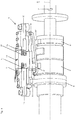
- Fig. 7 additionally shows the set-up of the apparatus, in which a radial actuator (8) can be seen which can either push or pull the repitching members from or to the rotation axis (2).
- the apparatus comprises one or more means adapted to interact with the radial guiding device (19) to ensure the repitching members (11, 12, 13) follow the trajectory defined by the radial guiding device (19).
- Such means are visible in Fig. 7 , but can also be part of the contact element (24) in Fig. 6 , and can be seen in Fig. 7 to inhibit further radial displacement once the contact element (24) is pressed against the radial guiding device (19).
- Fig. 8 also shows springs (8, 8', 8") as an actuator (but also co-functioning as - part of - connectors) to ensure the repitching members are pressed (or pulled) against the guiding device (19) in the radial direction.
Landscapes
- Engineering & Computer Science (AREA)
- Health & Medical Sciences (AREA)
- Mechanical Engineering (AREA)
- Heart & Thoracic Surgery (AREA)
- Epidemiology (AREA)
- Biomedical Technology (AREA)
- Manufacturing & Machinery (AREA)
- Vascular Medicine (AREA)
- Life Sciences & Earth Sciences (AREA)
- Animal Behavior & Ethology (AREA)
- General Health & Medical Sciences (AREA)
- Public Health (AREA)
- Veterinary Medicine (AREA)
- Absorbent Articles And Supports Therefor (AREA)
Claims (10)
- Verfahren zum Dehnen und Ändern des Abstandsmaßes eines elastischen Elements zur Anbringung an einem sich bewegenden Substrat, wobei das elastische Element in mindestens einer Längsrichtung dehnbar ist und das elastische Element in einem im Wesentlichen nicht-gedehnten Zustand eine anfängliche Länge entlang der Längenrichtung umfasst, wobei das Verfahren die folgenden Schritte umfasst:(1) Bereitstellen des elastischen Elements in im Wesentlichen nicht-gedehntem Zustand an einem Satz von Elementen zum Ändern des Abstandsmaßes (11, 12, 13) mit einem anfänglichen Zuführungsabstandsmaß, wobei der Satz von Elementen zum Ändern des Abstandsmaßes (11, 12, 13) mindestens ein erstes Element zum Ändern des Abstandsmaßes (11) und ein zweites Element zum Ändern des Abstandsmaßes (12) und optional ein oder mehrere Elemente zum Ändern des Abstandsmaßes (13), das/die zwischen dem ersten und dem zweiten Element zum Ändern des Abstandsmaßes (11, 12) angeordnet ist/sind, umfasst,(2) Aufnehmen der elastischen Elemente, die in nicht-gedehntem Zustand angeordnet werden, zwischen dem Satz von Elementen zum Ändern des Abstandsmaßes (11, 12, 13), wobei der Abstand zwischen dem ersten und dem zweiten Element zum Ändern des Abstandsmaßes (11, 12) der anfänglichen Länge des elastischen Elements entspricht,(3) Bewegen mindestens des ersten und des zweiten Elements zum Ändern des Abstandsmaßes (11, 12), dabei Befolgen von Bewegungsbahnen, die sich voneinander weg bewegen, dadurch Dehnen der elastischen Elemente, die zwischen den Elementen zum Ändern des Abstandsmaßes (11, 12) angeordnet sind, auf eine Anwendungslänge, die länger als die anfängliche Länge ist und die der Länge des elastischen Elements in elastisch gedehntem Zustand entspricht,wobei sich die Elemente zum Ändern des Abstandsmaßes (11, 12, 13) beim Überführen der elastischen Elemente mit selektiv variabler Geschwindigkeit bewegen, um das Anwendungsabstandsmaß des elastischen Elements in gedehntem Zustand auf dem Substrat selektiv zu variieren, wobei die Variierung der Geschwindigkeit der Elemente zum Ändern des Abstandsmaßes (11, 12, 13) das Anwendungsabstandsmaß des elastischen Elements in gedehntem Zustand auf dem Substrat bestimmt,
wobei während Schritt 3 der Satz elastische Elemente um eine gemeinsame Drehachse gedreht wird (2), während das elastische Element von der anfänglichen Länge auf die Anwendungslänge gedehnt wird. - Verfahren zum Dehnen und Ändern des Abstandsmaßes eines elastischen Elements zur Anbringung an einem sich bewegenden Substrat, wobei das elastische Element in mindestens einer Längsrichtung dehnbar ist und das elastische Element in einem im Wesentlichen nicht-gedehnten Zustand eine anfängliche Länge entlang der Längenrichtung umfasst, wobei das Verfahren die folgenden Schritte umfasst:(1) Bereitstellen des elastischen Elements in im Wesentlichen nicht-gedehntem Zustand an einem Satz von Elementen zum Ändern des Abstandsmaßes (11, 12, 13) mit einem anfänglichen Zuführungsabstandsmaß, wobei der Satz von Elementen zum Ändern des Abstandsmaßes (11, 12, 13) mindestens ein erstes Element zum Ändern des Abstandsmaßes (11) und ein zweites Element zum Ändern des Abstandsmaßes (12) und optional ein oder mehrere Elemente zum Ändern des Abstandsmaßes (13), das/die zwischen dem ersten und dem zweiten Element zum Ändern des Abstandsmaßes (11, 12) angeordnet ist, umfasst,(2) Aufnehmen der elastischen Elemente, die in nicht-gedehntem Zustand angeordnet werden, zwischen dem Satz von Elementen zum Ändern des Abstandsmaßes (11, 12, 13), wobei der Abstand zwischen dem ersten und dem zweiten Element zum Ändern des Abstandsmaßes (11, 12) der anfänglichen Länge des elastischen Elements entspricht,(3) Bewegen mindestens des ersten und des zweiten Elements zum Ändern des Abstandsmaßes (11, 12), dabei Befolgen von Bewegungsbahnen, die sich voneinander weg bewegen, dadurch Dehnen der elastischen Elemente, die zwischen den Elementen zum Ändern des Abstandsmaßes (11, 12, 13) angeordnet sind, auf eine Anwendungslänge, die länger als die anfängliche Länge ist und die der Länge des elastischen Elements in elastisch gedehntem Zustand entspricht,wobei sich die Elemente zum Ändern des Abstandsmaßes (11, 12, 13) beim Überführen der elastischen Elemente mit selektiv variabler Geschwindigkeit bewegen, um das Anwendungsabstandsmaß des elastischen Elements in gedehntem Zustand auf dem Substrat selektiv zu variieren, wobei die Variierung der Geschwindigkeit der Elemente zum Ändern des Abstandsmaßes das Anwendungsabstandsmaß des elastischen Elements in gedehntem Zustand auf dem Substrat bestimmt,
wobei sich während Schritt 3 die Elemente zum Ändern des Abstandsmaßes (11, 12, 13) des Satzes jeweils in einer im Wesentlichen symmetrischen Bewegungsbahn um eine Drehachse (2) bewegen, wobei die Elemente zum Ändern des Abstandsmaßes (11, 12, 13) in der Bewegungsbahn mit einer im Wesentlichen konstanten Drehgeschwindigkeit bewegt werden und wobei die Bewegungsbahn dadurch definiert wird, dass sie an mindestens einem Punkt der Bewegungsbahn einen anderen radialen Abstand zwischen den Elementen zum Ändern des Abstandsmaßes und der Drehachse (l} als der radiale Abstand zwischen den Elementen zum Ändern des Abstandsmaßes und der Drehachse an dem Punkt der Bewegungsbahn, an dem die elastischen Elemente an den Elementen zum Ändern des Abstandsmaßes (11, 12, 13) bereitgestellt werden, aufweist. - Verfahren nach dem vorhergehenden Schritt 2, dadurch gekennzeichnet, dass die Elemente zum Ändern des Abstandsmaßes (11, 12, 13) in der Bewegungsbahn mit einer im Wesentlichen konstanten Drehbewegung bewegt werden und wobei die Bewegungsbahn dadurch definiert wird, dass sie einen anderen radialen Abstand zwischen der Drehachse (2) und einem Punkt der Bewegungsbahn, an dem die elastischen Elemente an den Elementen zum Ändern des Abstandsmaßes (11, 12, 13) bereitgestellt werden, als zwischen der Drehachse (2) und mindestens einem anderen Punkt der Bewegungsbahn aufweist, wodurch das Abstandsmaß der elastischen Elemente geändert wird.
- Verfahren nach einem der vorhergehenden Ansprüche 2 oder 3, wobei der Satz elastischer Elemente um eine gemeinsame Drehachse (2) gedreht wird, während das elastische Element von der anfänglichen Länge auf die Anwendungslänge gedehnt wird, vorzugsweise wobei das erste und das zweite Element zum Ändern des Abstandsmaßes (11, 12) um die gemeinsame Drehachse (2) gedreht werden.
- Verfahren nach einem der Ansprüche 1 bis 4, wobei das elastische Element ein elastischer Streifen ist.
- Verfahren nach einem der Ansprüche 1 bis 5, wobei das Abstandsmaß des elastischen Elements gemäß einem vorab festgelegten Profil zum Ändern des Abstandsmaßes geändert wird und wobei das elastische Element gemäß einem vorab festgelegten Dehnungsprofil gedehnt wird, das eine im Wesentlichen sinusförmige Funktion der Winkelposition ist, oder wobei das elastische Element gemäß einem vorab festgelegten Dehnungsprofil gedehnt wird, wobei das Dehnungsprofil einen Abschnitt umfasst, der eine im Wesentlichen lineare Funktion der Zeit ist, über die das elastische Element auf den Elementen zum Ändern des Abstandsmaßes (11, 12, 13) bisher angeordnet war.
- Verfahren nach einem der Ansprüche 1 bis 6, wobei das elastische Element brückenartig zwischen dem Satz von Elementen zum Ändern des Abstandsmaßes (11, 12, 13) angeordnet wird, wenn das elastische Element in nicht-gedehntem Zustand ist und/oder gedehnt wird.
- Verfahren nach einem der Ansprüche 1 bis 7, wobei zwei, drei, vier oder mehr Sätze von Elementen zum Ändern des Abstandsmaßes (11, 12, 13) jeweils mindestens ein erstes Element zum Ändern des Abstandsmaßes (11) und ein zweites Elemente zum Ändern des Abstandsmaßes (12) umfassen und optional ein oder mehrere Elemente zum Ändern des Abstandsmaßes (13) zwischen dem ersten und dem zweiten Element zum Ändern des Abstandsmaßes angeordnet ist/sind, wobei ein elastisches Element von jedem Satz von Elementen zum Ändern des Abstandsmaßes (11, 12, 13) wie in Schritt (2) aufgenommen wird und wobei jeder Satz von Elementen zum Ändern des Abstandsmaßes (11, 12, 13) wie in Schritt (3) bewegt wird, um nacheinander, gleichzeitig oder teilweise gleichzeitig das Abstandsmaß jedes der elastischen Elemente zu ändern und jedes der elastischen Elemente nacheinander zu dehnen, wobei jeder Satz von Elementen zum Ändern des Abstandsmaßes (11, 12, 13) um die gemeinsame Drehachse (2) gedreht wird und wobei während Schritt (3) der Satz von elastischen Elementen um eine gemeinsame Drehachse (2) gedreht wird, während das elastische Element von der anfänglichen Länge auf die Anwendungslänge gedehnt wird.
- Vorrichtung zum Dehnen und Ändern des Abstandsmaßes eines elastischen Elements zur Anbringung an einem sich bewegenden Substrat, umfassend:a. eine erste und eine zweite Führungseinrichtung, die jeweils eine Bewegungsbahn definieren,b. einen Satz von Elementen zum Ändern des Abstandsmaßes (11, 12, 13) mit mindestens einem ersten Element zum Ändern des Abstandsmaßes (11) und einem zweiten Element zum Ändern des Abstandsmaßes (12) und optional einem oder mehreren Elementen zum Ändern des Abstandsmaßes (13), das/die zwischen dem ersten und dem zweiten Element zum Ändern des Abstandsmaßes (11, 12) angeordnet ist/sind,
wobei mindestens das erste Element zum Ändern des Abstandsmaßes (11) an der ersten Führungseinrichtung montiert und dazu eingerichtet ist, drehbar um eine erste Drehachse verlagerbar zu sein, wobei das erste Element zum Ändern des Abstandsmaßes (11) zum Befolgen der Bewegungsbahn gestaltet ist, die durch die erste Führungseinrichtung um die erste Drehachse definiert ist,
und wobei mindestens das zweite Element zum Ändern des Abstandsmaßes (12) an der zweiten Führungseinrichtung montiert und dazu eingerichtet ist, drehbar um eine zweite Drehachse verlagerbar zu sein, wobei das zweite Element zum Ändern des Abstandsmaßes (12) zum Befolgen der Bewegungsbahn gestaltet ist, die durch die zweite Führungseinrichtung um die zweite Drehachse definiert ist,(c) einen Aktor, der funktionsmäßig mit den Elementen zum Ändern des Abstandsmaßes (11, 12, 13) gekoppelt ist, zum Drehen der Elemente zum Ändern des Abstandsmaßes um die erste und/oder die zweite Drehachse, wobei der Aktor zum Drehen der Elemente zum Ändern des Abstandsmaßes (11, 12, 13) mit einer konstanten Drehgeschwindigkeit mindestens von einer anfänglichen Position (4) auf den Bewegungsbahnen bis zu einer Anwendungsposition (5) auf den Bewegungsbahnen gestaltet ist,wobei die erste und die zweite Führungseinrichtung dafür eingerichtet sind, das erste und das zweite Elemente zum Ändern des Abstandsmaßes (11, 12) bei einer anfänglichen Länge voneinander an der anfänglichen Position und bei einer Anwendungslänge voneinander an der Anwendungsposition zu beabstanden, wobei die Anwendungslänge größer ist als die anfängliche Länge,
wobei die erste und die zweite Führungseinrichtung dafür eingerichtet sind, das erste und das zweite Element zum Ändern des Abstandsmaßes an der anfänglichen Position bereitzustellen, wobei das erste und das zweite Element zum Ändern des Abstandsmaßes von der ersten beziehungsweise der zweiten Drehachse mit einem anfänglichen radialen Abstand beabstandet sind,
wobei die erste und die zweite Führungseinrichtung ferner dafür eingerichtet sind, das erste und das zweite Element zum Ändern des Abstandsmaßes an der Anwendungsposition bereitzustellen, wobei das erste und das zweite Element zum Ändern des Abstandsmaßes von der ersten beziehungsweise der zweiten Drehachse mit einem radialen Anwendungsabstand beabstandet sind,
dadurch gekennzeichnet, dass die Bewegungsbahnen dadurch definiert sind, dass sie mindestens einen Punkt auf den Bewegungsbahnen aufweisen, wobei der mindestens eine Punkt von den jeweiligen Drehachsen der Bewegungsbahnen mit einem radialen Abstand beabstandet ist, der sich von dem anfänglichen radialen Abstand und/oder von dem radialen Anwendungsabstand unterscheidet. - Vorrichtung nach dem vorhergehenden Anspruch 9, dadurch gekennzeichnet, dass sich der radiale Anwendungsabstand von dem anfänglichen radialen Abstand unterscheidet.
Applications Claiming Priority (2)
| Application Number | Priority Date | Filing Date | Title |
|---|---|---|---|
| EP16183096.3A EP3278779B1 (de) | 2016-08-05 | 2016-08-05 | Verbesserte vorrichtung und verfahren zum strecken und erneuten aufrichten von elastischen elementen |
| PCT/EP2017/068372 WO2018024498A1 (en) | 2016-08-05 | 2017-07-20 | Improved apparatus and method for stretching and repitching elastic members |
Publications (2)
| Publication Number | Publication Date |
|---|---|
| EP3451987A1 EP3451987A1 (de) | 2019-03-13 |
| EP3451987B1 true EP3451987B1 (de) | 2021-02-24 |
Family
ID=56618020
Family Applications (2)
| Application Number | Title | Priority Date | Filing Date |
|---|---|---|---|
| EP16183096.3A Active EP3278779B1 (de) | 2016-08-05 | 2016-08-05 | Verbesserte vorrichtung und verfahren zum strecken und erneuten aufrichten von elastischen elementen |
| EP17745691.0A Active EP3451987B1 (de) | 2016-08-05 | 2017-07-20 | Verbesserte vorrichtung und verfahren zum strecken und erneuten aufrichten von elastischen elementen |
Family Applications Before (1)
| Application Number | Title | Priority Date | Filing Date |
|---|---|---|---|
| EP16183096.3A Active EP3278779B1 (de) | 2016-08-05 | 2016-08-05 | Verbesserte vorrichtung und verfahren zum strecken und erneuten aufrichten von elastischen elementen |
Country Status (5)
| Country | Link |
|---|---|
| US (2) | US10966875B2 (de) |
| EP (2) | EP3278779B1 (de) |
| ES (1) | ES2714360T3 (de) |
| PL (1) | PL3278779T3 (de) |
| WO (1) | WO2018024498A1 (de) |
Families Citing this family (4)
| Publication number | Priority date | Publication date | Assignee | Title |
|---|---|---|---|---|
| CN113334790A (zh) * | 2021-04-28 | 2021-09-03 | 广州市兴世机械制造有限公司 | 一种弹性无纺布加工装置及加工方法 |
| EP4129628B1 (de) * | 2021-08-05 | 2023-11-08 | Fameccanica.Data S.p.A. | Vorrichtung und einheit zum querstrecken von elastischen folien |
| EP4129625B1 (de) * | 2021-08-05 | 2023-12-20 | Fameccanica.Data S.p.A. | Einheit zum querdehnen elastischer folien |
| US11618177B1 (en) | 2022-04-12 | 2023-04-04 | Bradley W Boesel | Orbital knife |
Family Cites Families (3)
| Publication number | Priority date | Publication date | Assignee | Title |
|---|---|---|---|---|
| FR2594651B1 (fr) * | 1986-02-21 | 1991-06-07 | Colgate Palmolive Co | Machine pour fixer sur une nappe en defilement continu des troncons tendus de bande elastique et installation pour la production de couches culottes en comportant application |
| US5407507A (en) | 1993-10-25 | 1995-04-18 | The Procter & Gamble Company | Method and apparatus for combining a tensioned elastic member with a moving substrate web |
| EP2260813B1 (de) * | 2009-05-29 | 2015-07-15 | Fameccanica.Data S.p.A. | Vorrichtung und Verfharen zur Herstellung von gespannte elastizierten Streifen, z.B. für Hygieneartikel und Computerprogrammprodukt für ihre Herstellung |
-
2016
- 2016-08-05 PL PL16183096T patent/PL3278779T3/pl unknown
- 2016-08-05 ES ES16183096T patent/ES2714360T3/es active Active
- 2016-08-05 EP EP16183096.3A patent/EP3278779B1/de active Active
-
2017
- 2017-07-20 WO PCT/EP2017/068372 patent/WO2018024498A1/en not_active Ceased
- 2017-07-20 EP EP17745691.0A patent/EP3451987B1/de active Active
- 2017-07-20 US US16/313,334 patent/US10966875B2/en active Active
-
2021
- 2021-03-03 US US17/190,529 patent/US11510823B2/en active Active
Non-Patent Citations (1)
| Title |
|---|
| None * |
Also Published As
| Publication number | Publication date |
|---|---|
| US11510823B2 (en) | 2022-11-29 |
| EP3451987A1 (de) | 2019-03-13 |
| PL3278779T3 (pl) | 2019-07-31 |
| EP3278779A1 (de) | 2018-02-07 |
| US20200179178A1 (en) | 2020-06-11 |
| ES2714360T3 (es) | 2019-05-28 |
| WO2018024498A1 (en) | 2018-02-08 |
| EP3278779B1 (de) | 2018-12-26 |
| US10966875B2 (en) | 2021-04-06 |
| US20210236343A1 (en) | 2021-08-05 |
Similar Documents
| Publication | Publication Date | Title |
|---|---|---|
| US11510823B2 (en) | Apparatus and method for stretching and repitching elastic members | |
| EP3496687B1 (de) | Verfahren und vorrichtung zur herstellung von saugfähigen artikeln | |
| EP0806928B1 (de) | Verfahren und vorrichtung zur herstellung von wegwerfartikeln | |
| US10377085B2 (en) | Device and method for forming ultrasonic welds on web materials in continuous movement | |
| US8133339B2 (en) | Bonding of elastomeric substrate under stretched conditions | |
| JP6605631B2 (ja) | 別個の物品を移送するための方法 | |
| EP1440027A1 (de) | Vorrichtung und verfahren zum anbringen von diskreten komponenten auf eine laufende materialbahn | |
| US6006637A (en) | Servo driven watercutter | |
| US5636558A (en) | Method and apparatus for directing fluid | |
| IT8368052A1 (it) | Procedimento ed apparecchiatura per la formazione di elementi elastici in tensione a partire da un nastro elastico continuo, particolarmente per la fabbricazione di prodotti sanitari quali pannolini monouso e simili. | |
| EP2652200B1 (de) | Vorrichtung und verfahren zur anbringung eines bandes in einem nichtlinearen netzmuster | |
| JP2010088750A (ja) | 複合シートの製造方法 | |
| US10285870B2 (en) | Apparatuses and methods for transferring and bonding substrates | |
| US10285869B2 (en) | Apparatuses and methods for transferring and bonding substrates | |
| JP6008703B2 (ja) | 伸縮性複合シートの製造装置および製造方法 | |
| CN109689959A (zh) | 用于将第一网以非线性图案施加到基础网的设备和方法 | |
| WO2004011712A1 (en) | Apparatus for forming folds in material | |
| CN107255106A (zh) | 多色多层弹簧连续自动化粘簧机及粘胶方法 |
Legal Events
| Date | Code | Title | Description |
|---|---|---|---|
| STAA | Information on the status of an ep patent application or granted ep patent |
Free format text: STATUS: UNKNOWN |
|
| STAA | Information on the status of an ep patent application or granted ep patent |
Free format text: STATUS: THE INTERNATIONAL PUBLICATION HAS BEEN MADE |
|
| PUAI | Public reference made under article 153(3) epc to a published international application that has entered the european phase |
Free format text: ORIGINAL CODE: 0009012 |
|
| STAA | Information on the status of an ep patent application or granted ep patent |
Free format text: STATUS: REQUEST FOR EXAMINATION WAS MADE |
|
| 17P | Request for examination filed |
Effective date: 20181204 |
|
| AK | Designated contracting states |
Kind code of ref document: A1 Designated state(s): AL AT BE BG CH CY CZ DE DK EE ES FI FR GB GR HR HU IE IS IT LI LT LU LV MC MK MT NL NO PL PT RO RS SE SI SK SM TR |
|
| AX | Request for extension of the european patent |
Extension state: BA ME |
|
| DAV | Request for validation of the european patent (deleted) | ||
| DAX | Request for extension of the european patent (deleted) | ||
| STAA | Information on the status of an ep patent application or granted ep patent |
Free format text: STATUS: EXAMINATION IS IN PROGRESS |
|
| 17Q | First examination report despatched |
Effective date: 20200429 |
|
| GRAP | Despatch of communication of intention to grant a patent |
Free format text: ORIGINAL CODE: EPIDOSNIGR1 |
|
| STAA | Information on the status of an ep patent application or granted ep patent |
Free format text: STATUS: GRANT OF PATENT IS INTENDED |
|
| RAP1 | Party data changed (applicant data changed or rights of an application transferred) |
Owner name: ONTEX BV |
|
| INTG | Intention to grant announced |
Effective date: 20200928 |
|
| GRAS | Grant fee paid |
Free format text: ORIGINAL CODE: EPIDOSNIGR3 |
|
| GRAA | (expected) grant |
Free format text: ORIGINAL CODE: 0009210 |
|
| STAA | Information on the status of an ep patent application or granted ep patent |
Free format text: STATUS: THE PATENT HAS BEEN GRANTED |
|
| AK | Designated contracting states |
Kind code of ref document: B1 Designated state(s): AL AT BE BG CH CY CZ DE DK EE ES FI FR GB GR HR HU IE IS IT LI LT LU LV MC MK MT NL NO PL PT RO RS SE SI SK SM TR |
|
| REG | Reference to a national code |
Ref country code: CH Ref legal event code: EP |
|
| REG | Reference to a national code |
Ref country code: DE Ref legal event code: R096 Ref document number: 602017033297 Country of ref document: DE |
|
| REG | Reference to a national code |
Ref country code: AT Ref legal event code: REF Ref document number: 1363559 Country of ref document: AT Kind code of ref document: T Effective date: 20210315 |
|
| REG | Reference to a national code |
Ref country code: IE Ref legal event code: FG4D |
|
| REG | Reference to a national code |
Ref country code: LT Ref legal event code: MG9D |
|
| REG | Reference to a national code |
Ref country code: NL Ref legal event code: MP Effective date: 20210224 |
|
| PG25 | Lapsed in a contracting state [announced via postgrant information from national office to epo] |
Ref country code: NO Free format text: LAPSE BECAUSE OF FAILURE TO SUBMIT A TRANSLATION OF THE DESCRIPTION OR TO PAY THE FEE WITHIN THE PRESCRIBED TIME-LIMIT Effective date: 20210524 Ref country code: PT Free format text: LAPSE BECAUSE OF FAILURE TO SUBMIT A TRANSLATION OF THE DESCRIPTION OR TO PAY THE FEE WITHIN THE PRESCRIBED TIME-LIMIT Effective date: 20210624 Ref country code: GR Free format text: LAPSE BECAUSE OF FAILURE TO SUBMIT A TRANSLATION OF THE DESCRIPTION OR TO PAY THE FEE WITHIN THE PRESCRIBED TIME-LIMIT Effective date: 20210525 Ref country code: HR Free format text: LAPSE BECAUSE OF FAILURE TO SUBMIT A TRANSLATION OF THE DESCRIPTION OR TO PAY THE FEE WITHIN THE PRESCRIBED TIME-LIMIT Effective date: 20210224 Ref country code: FI Free format text: LAPSE BECAUSE OF FAILURE TO SUBMIT A TRANSLATION OF THE DESCRIPTION OR TO PAY THE FEE WITHIN THE PRESCRIBED TIME-LIMIT Effective date: 20210224 Ref country code: BG Free format text: LAPSE BECAUSE OF FAILURE TO SUBMIT A TRANSLATION OF THE DESCRIPTION OR TO PAY THE FEE WITHIN THE PRESCRIBED TIME-LIMIT Effective date: 20210524 Ref country code: LT Free format text: LAPSE BECAUSE OF FAILURE TO SUBMIT A TRANSLATION OF THE DESCRIPTION OR TO PAY THE FEE WITHIN THE PRESCRIBED TIME-LIMIT Effective date: 20210224 |
|
| REG | Reference to a national code |
Ref country code: AT Ref legal event code: MK05 Ref document number: 1363559 Country of ref document: AT Kind code of ref document: T Effective date: 20210224 |
|
| PG25 | Lapsed in a contracting state [announced via postgrant information from national office to epo] |
Ref country code: LV Free format text: LAPSE BECAUSE OF FAILURE TO SUBMIT A TRANSLATION OF THE DESCRIPTION OR TO PAY THE FEE WITHIN THE PRESCRIBED TIME-LIMIT Effective date: 20210224 Ref country code: NL Free format text: LAPSE BECAUSE OF FAILURE TO SUBMIT A TRANSLATION OF THE DESCRIPTION OR TO PAY THE FEE WITHIN THE PRESCRIBED TIME-LIMIT Effective date: 20210224 Ref country code: PL Free format text: LAPSE BECAUSE OF FAILURE TO SUBMIT A TRANSLATION OF THE DESCRIPTION OR TO PAY THE FEE WITHIN THE PRESCRIBED TIME-LIMIT Effective date: 20210224 Ref country code: RS Free format text: LAPSE BECAUSE OF FAILURE TO SUBMIT A TRANSLATION OF THE DESCRIPTION OR TO PAY THE FEE WITHIN THE PRESCRIBED TIME-LIMIT Effective date: 20210224 Ref country code: SE Free format text: LAPSE BECAUSE OF FAILURE TO SUBMIT A TRANSLATION OF THE DESCRIPTION OR TO PAY THE FEE WITHIN THE PRESCRIBED TIME-LIMIT Effective date: 20210224 |
|
| PG25 | Lapsed in a contracting state [announced via postgrant information from national office to epo] |
Ref country code: IS Free format text: LAPSE BECAUSE OF FAILURE TO SUBMIT A TRANSLATION OF THE DESCRIPTION OR TO PAY THE FEE WITHIN THE PRESCRIBED TIME-LIMIT Effective date: 20210624 |
|
| PG25 | Lapsed in a contracting state [announced via postgrant information from national office to epo] |
Ref country code: EE Free format text: LAPSE BECAUSE OF FAILURE TO SUBMIT A TRANSLATION OF THE DESCRIPTION OR TO PAY THE FEE WITHIN THE PRESCRIBED TIME-LIMIT Effective date: 20210224 Ref country code: CZ Free format text: LAPSE BECAUSE OF FAILURE TO SUBMIT A TRANSLATION OF THE DESCRIPTION OR TO PAY THE FEE WITHIN THE PRESCRIBED TIME-LIMIT Effective date: 20210224 Ref country code: AT Free format text: LAPSE BECAUSE OF FAILURE TO SUBMIT A TRANSLATION OF THE DESCRIPTION OR TO PAY THE FEE WITHIN THE PRESCRIBED TIME-LIMIT Effective date: 20210224 Ref country code: SM Free format text: LAPSE BECAUSE OF FAILURE TO SUBMIT A TRANSLATION OF THE DESCRIPTION OR TO PAY THE FEE WITHIN THE PRESCRIBED TIME-LIMIT Effective date: 20210224 |
|
| REG | Reference to a national code |
Ref country code: DE Ref legal event code: R097 Ref document number: 602017033297 Country of ref document: DE |
|
| PG25 | Lapsed in a contracting state [announced via postgrant information from national office to epo] |
Ref country code: SK Free format text: LAPSE BECAUSE OF FAILURE TO SUBMIT A TRANSLATION OF THE DESCRIPTION OR TO PAY THE FEE WITHIN THE PRESCRIBED TIME-LIMIT Effective date: 20210224 Ref country code: DK Free format text: LAPSE BECAUSE OF FAILURE TO SUBMIT A TRANSLATION OF THE DESCRIPTION OR TO PAY THE FEE WITHIN THE PRESCRIBED TIME-LIMIT Effective date: 20210224 Ref country code: RO Free format text: LAPSE BECAUSE OF FAILURE TO SUBMIT A TRANSLATION OF THE DESCRIPTION OR TO PAY THE FEE WITHIN THE PRESCRIBED TIME-LIMIT Effective date: 20210224 |
|
| PLBE | No opposition filed within time limit |
Free format text: ORIGINAL CODE: 0009261 |
|
| STAA | Information on the status of an ep patent application or granted ep patent |
Free format text: STATUS: NO OPPOSITION FILED WITHIN TIME LIMIT |
|
| PG25 | Lapsed in a contracting state [announced via postgrant information from national office to epo] |
Ref country code: ES Free format text: LAPSE BECAUSE OF FAILURE TO SUBMIT A TRANSLATION OF THE DESCRIPTION OR TO PAY THE FEE WITHIN THE PRESCRIBED TIME-LIMIT Effective date: 20210224 Ref country code: AL Free format text: LAPSE BECAUSE OF FAILURE TO SUBMIT A TRANSLATION OF THE DESCRIPTION OR TO PAY THE FEE WITHIN THE PRESCRIBED TIME-LIMIT Effective date: 20210224 |
|
| 26N | No opposition filed |
Effective date: 20211125 |
|
| PG25 | Lapsed in a contracting state [announced via postgrant information from national office to epo] |
Ref country code: SI Free format text: LAPSE BECAUSE OF FAILURE TO SUBMIT A TRANSLATION OF THE DESCRIPTION OR TO PAY THE FEE WITHIN THE PRESCRIBED TIME-LIMIT Effective date: 20210224 |
|
| REG | Reference to a national code |
Ref country code: CH Ref legal event code: PL |
|
| PG25 | Lapsed in a contracting state [announced via postgrant information from national office to epo] |
Ref country code: MC Free format text: LAPSE BECAUSE OF FAILURE TO SUBMIT A TRANSLATION OF THE DESCRIPTION OR TO PAY THE FEE WITHIN THE PRESCRIBED TIME-LIMIT Effective date: 20210224 |
|
| REG | Reference to a national code |
Ref country code: BE Ref legal event code: MM Effective date: 20210731 |
|
| PG25 | Lapsed in a contracting state [announced via postgrant information from national office to epo] |
Ref country code: LI Free format text: LAPSE BECAUSE OF NON-PAYMENT OF DUE FEES Effective date: 20210731 Ref country code: CH Free format text: LAPSE BECAUSE OF NON-PAYMENT OF DUE FEES Effective date: 20210731 |
|
| PG25 | Lapsed in a contracting state [announced via postgrant information from national office to epo] |
Ref country code: IS Free format text: LAPSE BECAUSE OF FAILURE TO SUBMIT A TRANSLATION OF THE DESCRIPTION OR TO PAY THE FEE WITHIN THE PRESCRIBED TIME-LIMIT Effective date: 20210624 Ref country code: LU Free format text: LAPSE BECAUSE OF NON-PAYMENT OF DUE FEES Effective date: 20210720 |
|
| PG25 | Lapsed in a contracting state [announced via postgrant information from national office to epo] |
Ref country code: IE Free format text: LAPSE BECAUSE OF NON-PAYMENT OF DUE FEES Effective date: 20210720 Ref country code: BE Free format text: LAPSE BECAUSE OF NON-PAYMENT OF DUE FEES Effective date: 20210731 |
|
| PG25 | Lapsed in a contracting state [announced via postgrant information from national office to epo] |
Ref country code: CY Free format text: LAPSE BECAUSE OF FAILURE TO SUBMIT A TRANSLATION OF THE DESCRIPTION OR TO PAY THE FEE WITHIN THE PRESCRIBED TIME-LIMIT Effective date: 20210224 |
|
| P01 | Opt-out of the competence of the unified patent court (upc) registered |
Effective date: 20230527 |
|
| PG25 | Lapsed in a contracting state [announced via postgrant information from national office to epo] |
Ref country code: HU Free format text: LAPSE BECAUSE OF FAILURE TO SUBMIT A TRANSLATION OF THE DESCRIPTION OR TO PAY THE FEE WITHIN THE PRESCRIBED TIME-LIMIT; INVALID AB INITIO Effective date: 20170720 |
|
| PG25 | Lapsed in a contracting state [announced via postgrant information from national office to epo] |
Ref country code: MK Free format text: LAPSE BECAUSE OF FAILURE TO SUBMIT A TRANSLATION OF THE DESCRIPTION OR TO PAY THE FEE WITHIN THE PRESCRIBED TIME-LIMIT Effective date: 20210224 |
|
| PG25 | Lapsed in a contracting state [announced via postgrant information from national office to epo] |
Ref country code: MT Free format text: LAPSE BECAUSE OF FAILURE TO SUBMIT A TRANSLATION OF THE DESCRIPTION OR TO PAY THE FEE WITHIN THE PRESCRIBED TIME-LIMIT Effective date: 20210224 |
|
| PGFP | Annual fee paid to national office [announced via postgrant information from national office to epo] |
Ref country code: DE Payment date: 20250722 Year of fee payment: 9 |
|
| PGFP | Annual fee paid to national office [announced via postgrant information from national office to epo] |
Ref country code: IT Payment date: 20250731 Year of fee payment: 9 |
|
| PGFP | Annual fee paid to national office [announced via postgrant information from national office to epo] |
Ref country code: GB Payment date: 20250724 Year of fee payment: 9 |
|
| PGFP | Annual fee paid to national office [announced via postgrant information from national office to epo] |
Ref country code: FR Payment date: 20250723 Year of fee payment: 9 |
|
| PG25 | Lapsed in a contracting state [announced via postgrant information from national office to epo] |
Ref country code: TR Free format text: LAPSE BECAUSE OF FAILURE TO SUBMIT A TRANSLATION OF THE DESCRIPTION OR TO PAY THE FEE WITHIN THE PRESCRIBED TIME-LIMIT Effective date: 20210224 |