EP3453237A1 - Überlastsicherung - Google Patents
Überlastsicherung Download PDFInfo
- Publication number
- EP3453237A1 EP3453237A1 EP18401076.7A EP18401076A EP3453237A1 EP 3453237 A1 EP3453237 A1 EP 3453237A1 EP 18401076 A EP18401076 A EP 18401076A EP 3453237 A1 EP3453237 A1 EP 3453237A1
- Authority
- EP
- European Patent Office
- Prior art keywords
- tube
- spring assembly
- spring
- sleeve
- overload protection
- Prior art date
- Legal status (The legal status is an assumption and is not a legal conclusion. Google has not performed a legal analysis and makes no representation as to the accuracy of the status listed.)
- Granted
Links
Images



Classifications
-
- A—HUMAN NECESSITIES
- A01—AGRICULTURE; FORESTRY; ANIMAL HUSBANDRY; HUNTING; TRAPPING; FISHING
- A01B—SOIL WORKING IN AGRICULTURE OR FORESTRY; PARTS, DETAILS, OR ACCESSORIES OF AGRICULTURAL MACHINES OR IMPLEMENTS, IN GENERAL
- A01B61/00—Devices for, or parts of, agricultural machines or implements for preventing overstrain
- A01B61/04—Devices for, or parts of, agricultural machines or implements for preventing overstrain of the connection between tools and carrier beam or frame
- A01B61/044—Devices for, or parts of, agricultural machines or implements for preventing overstrain of the connection between tools and carrier beam or frame the connection enabling a yielding pivoting movement around a substantially horizontal and transverse axis
- A01B61/046—Devices for, or parts of, agricultural machines or implements for preventing overstrain of the connection between tools and carrier beam or frame the connection enabling a yielding pivoting movement around a substantially horizontal and transverse axis the device including an energy accumulator for restoring the tool to its working position
Definitions
- the invention relates to an overload protection according to the preamble of claim 1.
- a cultivator is provided with designed as crowded with tillage cultivation elements working elements.
- the cultivator is attached by means of a suitable connection to a tractor and is provided with a frame for receiving all working elements.
- the secured against overload tillage elements are mounted in a plurality of side by side in succession arranged rows of a part of the frame, which extends transversely to the direction.
- the second end face of the spring assembly is applied to a second spring plate, which is located at the upper end of the biasing tube and axially displaceable on the biasing tube.
- the pretensioning tube is threaded in this area and is guided through the second spring plate. By screwing a nut of the second spring plate is pressed in the axial direction of the spring assembly and biases this so before.
- the spring assembly is connected at a distance from the axis both with the frame and with the working element via joint axes. Due to the two joint axes, the overload protection is designed such that the Swinging movement to avoid when hitting an obstacle to a compression of the spring package leads.
- the upper spring plate is located on the side facing away from the spring package in contact with a Studentslasthalter. During the pivoting process, the entire device is rotated such that the Kochlasthalter is pressed in the axial direction on the upper spring plate. As a result, the spring pack is compressed and the necessary restoring force is created.
- a plastic tube sleeve is pushed over the pretensioning tube into the spring assembly.
- This tube sleeve surrounds the pretensioning tube and is also guided through the upper spring plate and is thus located in the interior of the spring assembly.
- the tube sleeve is thus between spring assembly and biasing tube.
- the invention is therefore based on the object to provide an overload protection for working elements of agricultural equipment, which is designed low friction and compact.
- the tube sleeve is held in contact with the upper spring plate by means of a compression spring, which is assigned to the lower end face of the tube sleeve. It is thus achieved that, after an evasive movement of the working element and the associated compression of the spring assembly, the tube sleeve returns to its initial position when the spring pack is relaxed and the wear tube is always protected against wear. It is also conceivable that the compression spring associated with the tube sleeve makes a contribution to the force built up by the spring assembly. Thus, the spring package can be made smaller overall, since an additional spring is used to build up the force.
- the inner diameter of the tube sleeve corresponds at least approximately to the outer diameter of the prestressing tube. This design has the effect that wear-resistant contact conditions are established for the relative movement between the tube sleeve and the pretensioning tube.
- the outer diameter of the tube sleeve is formed at least approximately equal to the inner diameter of the spring assembly, so that buckling or buckling is prevented.
- the spring assembly is supported on the bumps or wrinkles particularly critical point below the upper spring plate already at the beginning of buckling or buckling on the tube sleeve.
- the pipe sleeve is made of a wear-resistant plastic.
- the orderly wear-resistant contact conditions between tube sleeve and bias tube are so further improved.
- the overload holder extends from the connection of the working elements to the frame to the rear end of the spring assembly.
- This Mechanismlasthalter serves to transfer the applied spring force on the tine holder.
- FIG. 1 an agricultural implement is shown which in this embodiment is a cultivator 1 designed as a cultivator.
- the cultivator 1 is provided at its front end with a three-point coupling device 2 to connect to a tractor, not shown. To cultivate the soil as widely as possible, the cultivator is pulled behind the tractor in direction of travel 3.
- the three-point coupling device 2 is arranged at the front end of the multi-part frame 4.
- a plurality of working elements 5 is attached.
- the working elements 5 are each formed as a tine element 5.1 and provided at its upper end with an overload protection 6.
- a leveling unit 7 and a packer roller 8 In the direction of travel 3 behind the tine elements 5.1 is a leveling unit 7 and a packer roller 8, whose longitudinal axes are also transverse to the direction of travel 3.
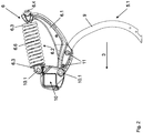
- FIG. 2 an embodiment of the tine element 5.1 with overload protection 6 and tine holder 9 is shown.
- the tine element 5.1 is fastened by means of the attachment 10 to the frame 4.
- the tine holder 9 and the overload protection 6, including the Matterlashalters 6.1 are rotatably connected via the hinge axes 10.1 by means of the attachment 10 to the frame 4. If the tine holder 9 encounters an obstacle in the working position when moving in the working direction, which corresponds to the direction of travel 3, it deflects upwards about an axis in a pivoting manner.
- This axis is the longitudinal axis of the transversely to the direction of travel 3 extending part of the frame 4 on which the evading tine element 5.1 is fixed respectively.
- the joint axes 10.1 are each at a distance to this axis. Due to the evasive movement of the entire device, the spring assembly 6.2 is compressed, as in Fig. 4 . 5 you can see. Here, the upper spring plate 6.3 is moved in the axial direction of the biasing tube 6.4.
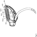
- a biasing tube 6.4 is guided, which is formed from an upper pipe section 6.4.1 and a lower pipe section 6.4.2 approximately same cross section, as the Fig. 3 shows.
- the spring package must 6.2 be biased.
- the upper spring plate 6.3 is pressed over the rear end of the Studentslashalters 6.1 by means of the clamping means 6.5 on the spring assembly 6.2.
- the clamping means 6.5 engages in the lower pipe section 6.4.2, which is rotatably fixedly connected to the frame 4 and thus braces all components together. As a result, the tine holder 9 is held in its normal working position during tillage.
- a tube sleeve 6.6 is provided. This tube sleeve 6.6 surrounds the pretensioning tube 6.4, is axially displaceable on the pretensioning tube 6.4 and is located with its upper end side in contact with the upper spring plate 6.3.
- the spring plate 6.3 is in the central region, where the biasing tube is passed through 6.4, recessed and forms a ringnutförmigen projection 6.3.1 in the tube sleeve 6.6 engages, so that the spring plate is guided only by the 6.3 6.6 6.6.
- the tube sleeve 6.6 is thus between the spring assembly 6.2 and the biasing tube 6.4 and does not penetrate the upper spring plate 6.3 in this embodiment, but supports it by means of a ringnutförmigen projection 6.3.1 on the spring plate 6.3 in the axial direction.
- an auxiliary spring 6.7 is provided, which is also arranged on the pretensioning tube 6.4.
- the designed as a compression spring auxiliary spring 6.7 is located on its underside on the lower spring plate 6.3 and so primarily ensures that the pipe sleeve 6.6 is always held in contact with the upper spring plate 6.3.
- the arrangement of the auxiliary spring 6.6 also allows it to provide a small contribution to the force generated by the spring assembly 6.2.
- the inner diameter of the tube sleeve 6.6 corresponds at least approximately to the outer diameter of the prestressing tube 6.4.
- the spring assembly 6.2 is formed by an outer compression spring 6.2.1 and an inner compression spring 6.2.2.
- the outer diameter of the tube sleeve 6.6 is at least approximately equal to the inner diameter of the inner compression spring 6.2.2 of the spring assembly selected 6.2.
- the inner compression spring 6.2.2 is in the critical area for buckling below the upper spring plate 6.3 on the pipe sleeve 6.6 and additionally supports the outer compression spring 6.2.1.
- the relative movement occurring is consequently limited to the compression of the inner compression spring 6.2.2 to the tube sleeve 6.6 and the sliding of the tube sleeve 6.6 on the biasing tube 6.4.
- the tubular sleeve 6.6 is made of wear-resistant plastic. This prevents the unfavorable case of metal rubbing against metal. Thus, the life of the overload protection 6 is extended.
- the Studentslasthalter 6.1 extends from the attachment 10 to the rear end of the spring assembly 6.2, where it is braced with the other components. Due to its curved shape and its rotatable attachment in the lower hinge axis 10.1, the overload holder 6.1 transmits the force applied by the spring assembly 6.2 force on the tine holder 9. The tine holder 9 is attached by means of screw 11 to the Matterlasthalter 6.1.
Landscapes
- Life Sciences & Earth Sciences (AREA)
- Engineering & Computer Science (AREA)
- Mechanical Engineering (AREA)
- Soil Sciences (AREA)
- Environmental Sciences (AREA)
- Soil Working Implements (AREA)
- Agricultural Machines (AREA)
Abstract
Description
- Eine derartige Überlastsicherung ist in
EP 1 125 488 B1 beschrieben. Ein Grubber ist mit als mit Scharen bestückten Bodenbearbeitungselementen ausgebildeten Arbeitselementen versehen. Der Grubber wird mittels einer geeigneten Anbindung an eine Zugmaschine angehangen und ist mit einem Rahmen zur Aufnahme sämtlicher Arbeitselemente versehen. Die vor Überlast gesicherten Bodenbearbeitungselemente sind in einer Vielzahl nebeneinander in hintereinander angeordneten Reihen an einem Teil des Rahmens befestigt, der quer zur Arbeitsrichtung verläuft. - Bei Auftreffen der Bodenbearbeitungselemente auf ein Hindernis, weichen diese um die Längsachse des Teiles des Rahmens an dem sie befestigt sind aus indem sie um diese Achse schwenken. Die Schwenkbewegung findet hierbei entgegen einer Kraft statt, die in Arbeitsrichtung wirkt und dafür sorgt, dass die Bodenbearbeitungselemente nach dem Ausweichvorgang wieder in Arbeitsposition zurückkehren. Die Kraft in Arbeitsrichtung wird erzeugt von einem Federpaket. Zur Krafterzeugung ist es notwendig, dass das Federpaket vorgespannt wird. Hierzu wird ein Vorspannrohr durch das als Spiraldruckfeder ausgebildete Federpaket geführt. An seinem unteren Ende ist an dem Vorspannrohr ein erster Federteller befestigt an dem die erste Stirnseite des Federpakets anliegt. Die zweite Stirnseite des Federpakets liegt an einem zweiten Federteller an, welcher sich am oberen Ende des Vorspannrohres befindet und axial auf dem Vorspannrohr verschiebbar ist. Das Vorspannrohr ist in diesem Bereich mit einem Gewinde versehen und wird durch den zweiten Federteller hindurch geführt. Durch das Aufschrauben einer Mutter wird der zweite Federteller in axialer Richtung auf das Federpaket gedrückt und spannt dieses so vor.
- Das Federpaket ist jeweils im Abstand zur Achse sowohl mit dem Rahmen als auch mit dem Arbeitselement über Gelenkachsen verbunden. Durch die beiden Gelenkachsen ist die Überlastsicherung derart gestaltet dass die Schwenkbewegung zum Ausweichen bei Auftreffen auf ein Hindernis zu einem Komprimieren des Federpakets führt.
- Der obere Federteller befindet sich auf der dem Federpaket abgewandten Seite in Anlage an einen Überlasthalter. Bei dem Schwenkvorgang wird die gesamte Vorrichtung derart verdreht, dass der Überlasthalter in axialer Richtung auf den oberen Federteller gepresst wird. Dadurch wird das Federpaket komprimiert und die notwendige Rückstellkraft entsteht.
- Um den Verschleiß durch den Führungskontakt des Federpaketes auf dem Vorspannrohr bei Komprimieren und Entlasten des Federpaketes zu verringern, wird eine Rohrhülse aus Kunststoff über das Vorspannrohr in das Federpaket geschoben. Diese Rohrhülse umgibt das Vorspannrohr und wird ebenfalls durch den oberen Federteller hindurch geführt und befindet sich so im Inneren des Federpakets. Die Rohrhülse befindet sich somit zwischen Federpaket und Vorspannrohr. Bei Komprimieren und Entlasten des Federpakets gleiten also sowohl das Federpaket, als auch der Federteller auf der Rohrhülse. Erfahrungsgemäß neigt bei diesem Vorgang das Federpaket dazu Auszubeulen bzw. Auszuknicken, was dazu führt dass der obere Federteller kippt. Dies hat den Nachteil, dass für die großen Relativbewegungen zwischen Federteller und Rohrhülse ein ungünstiger Reibkontakt entsteht. Zudem entsteht durch die Relativbewegung zwischen Federpaket und Rohrhülse viel Reibung, die zu nachteiligem Verschleiß führt, und die Rohrhülse muss vergleichsweise lang ausgebildet werden.
- Der Erfindung liegt daher die Aufgabe zu Grunde, eine Überlastsicherung für Arbeitselemente landwirtschaftlicher Geräte zu schaffen, die reibungsarm und kompakt gestaltet ist.
- Diese Aufgabe wird erfindungsgemäß dadurch gelöst, dass die Rohrhülse axial verschiebbar auf dem Vorspannrohr angeordnet ist und dass die Rohrhülse mit ihrer einen Stirnfläche an der Federplatte in Anlage gehalten wird.
- Infolge dieser Maßnahme wird erreicht, dass ein Verkippen der oberen Federplatte durch Ausbeulen bzw. Ausknicken der Federn zumindest annährend verhindert wird und keine Relativbewegung zwischen Federplatte und Rohrhülse entsteht. Zudem wird die Relativbewegung zwischen Federpaket und Rohrhülse auf ein Minimum begrenzt. Der Reibkontakt beschränkt sich folglich im Wesentlichen auf die Relativbewegung zwischen Rohrhülse und Vorspannrohr, die ein günstiges Reibpaar bilden. Dies hat zum Vorteil, dass der Verschleiß erheblich verringert wird. Des Weiteren kann die Rohrhülse wesentlich kompakter gestaltet werden. Dadurch, dass sie axial verschiebbar auf dem Vorspannrohr ist muss sie nicht mehr den gesamten Federweg, den der obere Federteller zurücklegt, abdecken, sondern ist auf die Länge beschränkt, die notwendig ist, um ein Ausbeulen bzw. Ausknicken des Federpakets zu verhindern. Diese Länge kann sehr kurz gehalten werden, da die Stelle unmittelbar unter dem oberen Federteller für ein Ausbeulen bzw. Ausknicken des Federpaketes besonders kritisch ist. Die Reibung zwischen dem Federpaket und der Rohrhülse beschränkt sich auf die Stauchung des Federpakets in dem dem Federteller benachbarten Bereich.
- Erfindungsgemäß ist vorgesehen, dass die Rohrhülse über eine Druckfeder, die der unteren Stirnfläche der Rohrhülse zugeordnet ist, in Anlage an die obere Federplatte gehalten wird. So wird erreicht, dass nach einer Ausweichbewegung des Arbeitselementes und dem damit verbundenen Komprimieren des Federpakets die Rohrhülse bei Entspannen des Federpakets in ihre Ausgangslage zurückkehrt und stets das Vorspannrohr vor Verschleiß schützt. Weiter ist denkbar, dass die der Rohrhülse zugeordnete Druckfeder einen Beitrag zu der von dem Federpaket aufgebauten Kraft leistet. So kann das Federpaket insgesamt kleiner dimensioniert werden, da eine zusätzliche Feder zum Aufbau der Kraft genutzt wird.
- In einer bevorzugten Ausführungsform entspricht der Innendurchmesser der Rohrhülse zumindest annährend dem Außendurchmesser des Vorspannrohres. Diese Gestaltung bewirkt, dass sich für die Relativbewegung zwischen Rohrhülse und Vorspannrohr verschleißarme Kontaktbedingungen einstellen.
- In einer erfindungsgemäßen Ausführungsform wird der Außendurchmesser der Rohrhülse zumindest annährend gleich dem Innendurchmesser des Federpakets ausgebildet, so dass ein Ausbeulen bzw. Ausknicken verhindert wird. Das Federpaket stützt sich an der für Beulen bzw. Knicken besonders kritischen Stelle unterhalb des oberen Federtellers bereits beim Beginn des Ausbeulens bzw. Ausknickens auf der Rohrhülse ab.
- In vorteilhafter Weise ist die Rohrhülse aus einem verschleißfesten Kunststoff gefertigt. Die anordnungsgemäß verschleißarmen Kontaktbedingungen zwischen Rohrhülse und Vorspannrohr werden so weiter verbessert.
- In einer bevorzugten Ausführung der Erfindung, erstreckt sich der Überlasthalter von der Anbindung der Arbeitselemente an den Rahmen bis zum hinteren Ende des Federpakets. Dieser Überlasthalter dient der Übertragung der aufgebrachten Federkraft auf den Zinkenhalter.
- Weitere Einzelheiten der Erfindung sind der Beispielsbeschreibung und den Zeichnungen zu entnehmen. Die Zeichnungen zeigen
- Fig.1
- landwirtschaftliches Gerät, hier ein als Grubber ausgebildetes Bodenbearbeitungsgerät in perspektivischer Ansicht,
- Fig.2
- Zinkenelement mit Überlastsicherung in Arbeitsposition und in Seitenansicht,
- Fig.3
- Zinkenelement, gemäß
Fig. 2 , in Schnittansicht, - Fig.4
- Zinkenelement mit Überlastsicherung in Ausweichposition und in Seitenansicht,
- Fig.5
- Zinkenelement, gemäß
Fig.4 , in Schnittansicht. - In der
Fig. 1 ist ein landwirtschaftliches Gerät gezeigt, welches in dieser Ausführungsform ein als Grubber 1 ausgebildetes Bodenbearbeitungsgerät ist. Der Grubber 1 ist an seinem vorderen Ende mit einer Dreipunktkupplungsvorrichtung 2 versehen, um ihn mit einer nicht dargestellten Zugmaschine zu verbinden. Zur möglichst flächendeckenden Bodenkultivierung wird der Grubber so hinter der Zugmaschine in Fahrtrichtung 3 gezogen. - Die Dreipunktkupplungsvorrichtung 2 ist am vorderen Ende des mehrteiligen Rahmens 4 angeordnet. Dahinterliegend, an drei hintereinander angeordneten und quer zur Fahrtrichtung 3 verlaufenden Teilen des Rahmens 4 ist eine Vielzahl von Arbeitselementen 5 befestigt. In der vorliegenden Ausführungsform sind die Arbeitselemente 5 jeweils als Zinkenelement 5.1 ausgebildet und an ihrem oberen Ende mit einer Überlastsicherung 6 versehen. In Fahrtrichtung 3 hinter den Zinkenelementen 5.1 liegt eine Einebnungseinheit 7 und eine Packerwalze 8, deren Längsachsen ebenfalls quer zur Fahrtrichtung 3 verlaufen.
- In der
Fig. 2 ist eine Ausführungsform des Zinkenelements 5.1 mit Überlastsicherung 6 und Zinkenhalter 9 gezeigt. Das Zinkenelement 5.1 wird mittels der Befestigung 10 am Rahmen 4 befestigt. Der Zinkenhalter 9 und die Überlastsicherung 6, inklusive des Überlasthalters 6.1, sind über die Gelenkachsen 10.1 drehbar mittels der Befestigung 10 mit dem Rahmen 4 verbunden. Trifft der Zinkenhalter 9 in Arbeitsposition bei Bewegung in Arbeitsrichtung, die der Fahrtrichtung 3 entspricht, auf ein Hindernis auf, so weicht dieser um eine Achse schwenkend nach oben aus. Diese Achse ist die Längsachse des quer zur Fahrtrichtung 3 verlaufenden Teils des Rahmens 4 an dem das ausweichende Zinkenelement 5.1 jeweils befestigt ist. Die Gelenkachsen 10.1 befinden sich jeweils im Abstand zu dieser Achse. Durch die Ausweichbewegung der gesamten Vorrichtung wird das Federpaket 6.2 komprimiert, wie inFig. 4 ,5 zu sehen ist. Hierbei wird der obere Federteller 6.3 in axialer Richtung des Vorspannrohres 6.4 verschoben. - Diese Ausweichbewegung findet entgegen einer von dem Federpaket 6.2 erzeugten Kraft statt. Durch das Innere des Federpakets 6.2 ist ein Vorspannrohr 6.4 geführt, welches aus einem oberen Rohrabschnitt 6.4.1 und einem unteren Rohrabschnitt 6.4.2 annährend gleichen Querschnitts gebildet wird, wie die
Fig. 3 zeigt. Damit die oben genannte Kraft auftritt, muss das Federpaket 6.2 vorgespannt sein. Hierzu ist der obere Federteller 6.3 über das hintere Ende des Überlasthalters 6.1 mittels des Spannmittels 6.5 auf das Federpaket 6.2 gepresst. Das Spannmittel 6.5 greift in den unteren Rohrabschnitt 6.4.2 ein, der drehbar fest mit dem Rahmen 4 verbunden ist und verspannt somit alle Komponenten miteinander. Hierdurch wird der Zinkenhalter 9 in seiner normalen Arbeitsposition während der Bodenbearbeitung gehalten. - Dadurch, dass bei der Ausweichbewegung eine Relativbewegung zwischen einerseits dem Federpaket 6.2 und dem oberen Federteller 6.3 und andererseits dem Vorspannrohr 6.4 auftritt, entsteht reibungsbedingter Verschleiß an den gegeneinander bewegten Komponenten. Um das Vorspannrohr 6.4 im Innern des Federpakets 6.2 vor diesem Verschleiß zu schützen, ist eine Rohrhülse 6.6 vorgesehen. Diese Rohrhülse 6.6 umgibt das Vorspannrohr 6.4, ist axial auf dem Vorspannrohr 6.4 verschiebbar und befindet sich mit seiner oberen Stirnseite in Anlage an den oberen Federteller 6.3. Der Federteller 6.3 ist im mittleren Bereich, wo das Vorspannrohr 6.4 hindurch geführt ist, ausgespart und bildet einen ringnutförmigen Vorsprung 6.3.1 in den die Rohrhülse 6.6 eingreift, so dass der Federteller 6.3 einzig von der Rohrhülse 6.6 geführt wird. Die Rohrhülse 6.6 befindet sich somit zwischen dem Federpaket 6.2 und dem Vorspannrohr 6.4 und durchdringt nicht den oberen Federteller 6.3 in dieser Ausführungsform, sondern stützt diesen mit Hilfe eines ringnutförmigen Vorsprungs 6.3.1 am Federteller 6.3 in axialer Richtung ab.
- An der unteren Stirnseite der Rohrhülse 6.6 ist eine Hilfsfeder 6.7 vorgesehen, die ebenfalls auf dem Vorspannrohr 6.4 angeordnet ist. Die als Druckfeder ausgeführte Hilfsfeder 6.7 liegt an ihrer Unterseite auf dem unteren Federteller 6.3 auf und sorgt so in erster Linie dafür, dass die Rohrhülse 6.6 immer in Anlage an den oberen Federteller 6.3 gehalten wird. Die Anordnung der Hilfsfeder 6.6 erlaubt es weiterhin, dass sie einen kleinen Beitrag zu der von dem Federpaket 6.2 erzeugten Kraft liefert.
- Wie in
Fig. 3 zu sehen ist, entspricht der Innendurchmesser der Rohrhülse 6.6 zumindest annährend dem Außendurchmesser des Vorspannrohres 6.4. Vorteilhafter Weise kommt es so zu einem gleichmäßigen Kontakt zwischen Vorspannrohr 6.4 und Rohrhülse 6.6, bei dem sich der von der inneren Druckfeder 6.2.2 auf die Rohrhülse 6.6 wirkende Druck flächig verteilt. Das Federpaket 6.2 wird gebildet durch eine äußere Druckfeder 6.2.1 und eine innere Druckfeder 6.2.2. In Analoger Überlegung ist der Außendurchmesser der Rohrhülse 6.6 zumindest annährend gleich dem Innendurchmesser der inneren Druckfeder 6.2.2 des Federpakets 6.2 gewählt. Zusätzlich wird so verhindert, dass das Federpaket 6.2 bei der Komprimierung durch die Ausweichbewegung ausbeulen oder ausknicken kann. Die innere Druckfeder 6.2.2 liegt in dem für Knicken kritischen Bereich unterhalb des oberen Federtellers 6.3 an der Rohrhülse 6.6 an und stützt zusätzlich die äußere Druckfeder 6.2.1. - In der dargestellten Ausführungsform der Erfindung beschränkt sich die auftretende Relativbewegung folglich auf die der Stauchung der inneren Druckfeder 6.2.2 zur Rohrhülse 6.6 und das Gleiten der Rohrhülse 6.6 auf dem Vorspannrohr 6.4. Um für diese Reibpartner günstige Voraussetzungen zu schaffen, ist vorgesehen die Rohrhülse 6.6 aus verschleißfestem Kunststoff zu fertigen. So wird der ungünstige Fall verhindert, dass Metall auf Metall reibt. Somit wird die Lebensdauer der Überlastsicherung 6 verlängert.
- Der Überlasthalter 6.1 erstreckt sich von der Befestigung 10 bis zum hinteren Ende des Federpakets 6.2, wo er mit den anderen Komponenten verspannt wird. Durch seine geschwungene Form und seiner drehbaren Festlegung in der unteren Gelenkachse 10.1 überträgt der Überlasthalter 6.1 die von dem Federpaket 6.2 aufgebrachte Kraft auf den Zinkenhalter 9. Der Zinkenhalter 9 ist mit Hilfe von Schraubverbindungen 11 an dem Überlasthalter 6.1 befestigt.
-
- 1
- Grubber
- 2
- Dreipunktkupplungsvorrichtung
- 3
- Fahrtrichtung
- 4
- Rahmen
- 5
- Arbeitselement
- 5.1
- Zinkenelement
- 6
- Überlastsicherung
- 6.1
- Überlasthalter
- 6.2
- Federpaket
- 6.2.1
- äußere Druckfeder
- 6.2.2
- innere Druckfeder
- 6.3
- Federteller
- 6.3.1
- Vorsprung
- 6.4
- Vorspannrohr
- 6.4.1
- oberer Rohrabschnitt
- 6.4.2
- unterer Rohrabschnitt
- 6.5
- Spannmittel
- 6.6
- Rohrhülse
- 6.7
- Hilfsfeder
- 7
- Einebnungseinheit
- 8
- Packerwalze
- 9
- Zinkenhalter
- 10
- Befestigung
- 10.1
- Gelenkachse
- 11
- Schraubverbindung
Claims (7)
- Überlastsicherung für Arbeitselemente landwirtschaftlicher Geräte, insbesondere als Grubber ausgebildete Bodenbearbeitungsgeräte, wobei die Arbeitselemente beim Auftreffen auf Hindernissen entgegen der Arbeitsrichtung gegen die Kraft zumindest eines Federpakets ausweichen können, wobei die Arbeitselemente um eine Achse mit dem Rahmen schwenkbar verbunden sind, wobei das Federpaket jeweils im Abstand zur Achse sowohl mit dem Rahmen als auch mit dem Arbeitselement über Gelenkachsen verbunden ist, wobei das Federpaket mit Hilfe eines Vorspannrohres und einer Federplatte vorgespannt wird, wobei die Federplatte zwischen dem Federpaket und dem vor Überlast gesichertem Arbeitselement angeordnet ist und zwischen dem Vorspannrohr und dem Federpaket ein als Rohrhülse ausgebildeter Verschleißschutz vorgesehen ist, dadurch gekennzeichnet, dass die Rohrhülse axial verschiebbar auf dem Vorspannrohr angeordnet ist, dass die Rohrhülse mit ihrer einen Stirnfläche an der Federplatte in Anlage gehalten wird.
- Überlastsicherung nach Anspruch 1, dadurch gekennzeichnet, dass die Rohrhülse über eine Druckfeder, die der anderen Stirnfläche der Rohrhülse zugeordnet ist, in Anlage an die Federplatte gehalten wird.
- Überlastsicherung nach Anspruch 2, dadurch gekennzeichnet, dass die der Rohrhülse zugeordnete Druckfeder einen Beitrag zu der von dem Federpaket aufgebauten Kraft leistet.
- Überlastsicherung nach einem der vorstehenden Ansprüche, dadurch gekennzeichnet, dass der Innendurchmesser der Rohrhülse zumindest annährend dem Außendurchmesser des Vorspannrohres entspricht.
- Überlastsicherung nach einem der vorstehenden Ansprüche, dadurch gekennzeichnet, dass der Außendurchmesser der Rohrhülse zumindest annährend dem Innendurchmesser des Federpakets entspricht.
- Überlastsicherung nach einem der vorstehenden Ansprüche, dadurch gekennzeichnet, dass die Rohrhülse aus einem verschleißfestem Kunststoff besteht.
- Überlastsicherung nach einem der vorstehenden Ansprüche, dadurch gekennzeichnet, dass sich von der Anbindung der Arbeitselemente an den Rahmen bis zum hinteren Ende des Federpakets ein Überlasthalter erstreckt.
Priority Applications (1)
| Application Number | Priority Date | Filing Date | Title |
|---|---|---|---|
| PL18401076T PL3453237T3 (pl) | 2017-09-07 | 2018-08-28 | Element roboczy z zabezpieczeniem przed przeciążeniem |
Applications Claiming Priority (1)
| Application Number | Priority Date | Filing Date | Title |
|---|---|---|---|
| DE102017120608.6A DE102017120608B4 (de) | 2017-09-07 | 2017-09-07 | Überlastsicherung |
Publications (2)
| Publication Number | Publication Date |
|---|---|
| EP3453237A1 true EP3453237A1 (de) | 2019-03-13 |
| EP3453237B1 EP3453237B1 (de) | 2020-01-29 |
Family
ID=63708258
Family Applications (1)
| Application Number | Title | Priority Date | Filing Date |
|---|---|---|---|
| EP18401076.7A Active EP3453237B1 (de) | 2017-09-07 | 2018-08-28 | Arbeitselement mit überlastsicherung |
Country Status (3)
| Country | Link |
|---|---|
| EP (1) | EP3453237B1 (de) |
| DE (1) | DE102017120608B4 (de) |
| PL (1) | PL3453237T3 (de) |
Cited By (1)
| Publication number | Priority date | Publication date | Assignee | Title |
|---|---|---|---|---|
| LU103366B1 (de) * | 2024-08-27 | 2026-02-27 | Benedict Kolb | Überlastsicherung für ein Bodenbearbeitungsgerät |
Citations (4)
| Publication number | Priority date | Publication date | Assignee | Title |
|---|---|---|---|---|
| FR2498875A1 (fr) * | 1981-02-03 | 1982-08-06 | Gason Pty Ltd A F | Support assemble articule pour instruments aratoires travaillant le sol |
| CA2199335A1 (en) * | 1997-03-06 | 1998-09-06 | David A. Dobson | Spring Trip Shank Assembly Having Quick-Dropping Trip-Out Force and Improved Resetting Ability |
| DE20008386U1 (de) * | 2000-05-10 | 2000-12-21 | Lemken GmbH & Co. KG, 46519 Alpen | Überlastsicherung für Grubber |
| EP1125488B1 (de) | 2000-02-17 | 2004-07-14 | Lemken GmbH & Co. KG | Bodenbearbeitungsgerät mit Überlastsicherung |
-
2017
- 2017-09-07 DE DE102017120608.6A patent/DE102017120608B4/de active Active
-
2018
- 2018-08-28 PL PL18401076T patent/PL3453237T3/pl unknown
- 2018-08-28 EP EP18401076.7A patent/EP3453237B1/de active Active
Patent Citations (4)
| Publication number | Priority date | Publication date | Assignee | Title |
|---|---|---|---|---|
| FR2498875A1 (fr) * | 1981-02-03 | 1982-08-06 | Gason Pty Ltd A F | Support assemble articule pour instruments aratoires travaillant le sol |
| CA2199335A1 (en) * | 1997-03-06 | 1998-09-06 | David A. Dobson | Spring Trip Shank Assembly Having Quick-Dropping Trip-Out Force and Improved Resetting Ability |
| EP1125488B1 (de) | 2000-02-17 | 2004-07-14 | Lemken GmbH & Co. KG | Bodenbearbeitungsgerät mit Überlastsicherung |
| DE20008386U1 (de) * | 2000-05-10 | 2000-12-21 | Lemken GmbH & Co. KG, 46519 Alpen | Überlastsicherung für Grubber |
Cited By (1)
| Publication number | Priority date | Publication date | Assignee | Title |
|---|---|---|---|---|
| LU103366B1 (de) * | 2024-08-27 | 2026-02-27 | Benedict Kolb | Überlastsicherung für ein Bodenbearbeitungsgerät |
Also Published As
| Publication number | Publication date |
|---|---|
| PL3453237T3 (pl) | 2020-06-29 |
| EP3453237B1 (de) | 2020-01-29 |
| DE102017120608B4 (de) | 2023-01-05 |
| DE102017120608A1 (de) | 2019-03-07 |
Similar Documents
| Publication | Publication Date | Title |
|---|---|---|
| EP0628236B1 (de) | Höhenverstellbares Gerät | |
| DE2106263C3 (de) | Drehmoment-Schraubenschlüssel | |
| EP3053438A1 (de) | Verteilergestänge | |
| DE1557738C3 (de) | ||
| EP0081742A1 (de) | Über ein Feld vorwärts bewegbares Bodenbearbeitungsgerät | |
| EP3053436B1 (de) | Verteilergestänge | |
| EP1951024B1 (de) | Bodenbearbeitungsgerät mit kurbelschutz | |
| DE202017100339U1 (de) | Schneidmesser-Überlastsicherung mit Schwenklasche | |
| EP3453237B1 (de) | Arbeitselement mit überlastsicherung | |
| EP2989873B1 (de) | Gefederter spurlockerer für landwirtschaftliche maschinen | |
| EP1911339B1 (de) | Doppelscheibenschar mit Tiefenführungsrolle und Energiespeicher | |
| EP0556459B1 (de) | Aufsattel- oder Anhänge-Drehpflug | |
| DE3617003A1 (de) | Schneideinrichtung fuer halm- und blattgut | |
| EP3053437B1 (de) | Verteilergestänge | |
| EP0567720B1 (de) | Steckbolzenverbindung | |
| EP1856965B1 (de) | Drehpflug mit Überlastsicherung | |
| DE19810682C1 (de) | Überlastgesicherter Bodengrubber | |
| DE1457677C2 (de) | Kupplungsvorrichtung zum Anschließen von Anbaugeräten an das Dreipunktgestänge von Schleppern | |
| AT397594B (de) | Steinsicherungsvorrichtung für drehpflüge | |
| AT398880B (de) | Schneideinrichtung für halm- und blattgut | |
| DE102010020431B4 (de) | Mähmaschine | |
| DE2950551C2 (de) | Steinsicherung | |
| EP4173457A1 (de) | Anordnung mit einem arbeitswerkzeug zur bodenbearbeitung für eine landwirtschaftliche maschine sowie landwirtschaftliche maschine | |
| DE10007156A1 (de) | Zinken mit Überlastsicherung | |
| DE4104290C2 (de) | Steinsicherungsvorrichtung für Pflüge |
Legal Events
| Date | Code | Title | Description |
|---|---|---|---|
| PUAI | Public reference made under article 153(3) epc to a published international application that has entered the european phase |
Free format text: ORIGINAL CODE: 0009012 |
|
| STAA | Information on the status of an ep patent application or granted ep patent |
Free format text: STATUS: THE APPLICATION HAS BEEN PUBLISHED |
|
| AK | Designated contracting states |
Kind code of ref document: A1 Designated state(s): AL AT BE BG CH CY CZ DE DK EE ES FI FR GB GR HR HU IE IS IT LI LT LU LV MC MK MT NL NO PL PT RO RS SE SI SK SM TR |
|
| AX | Request for extension of the european patent |
Extension state: BA ME |
|
| STAA | Information on the status of an ep patent application or granted ep patent |
Free format text: STATUS: REQUEST FOR EXAMINATION WAS MADE |
|
| 17P | Request for examination filed |
Effective date: 20190801 |
|
| RBV | Designated contracting states (corrected) |
Designated state(s): AL AT BE BG CH CY CZ DE DK EE ES FI FR GB GR HR HU IE IS IT LI LT LU LV MC MK MT NL NO PL PT RO RS SE SI SK SM TR |
|
| GRAP | Despatch of communication of intention to grant a patent |
Free format text: ORIGINAL CODE: EPIDOSNIGR1 |
|
| STAA | Information on the status of an ep patent application or granted ep patent |
Free format text: STATUS: GRANT OF PATENT IS INTENDED |
|
| INTG | Intention to grant announced |
Effective date: 20191024 |
|
| GRAS | Grant fee paid |
Free format text: ORIGINAL CODE: EPIDOSNIGR3 |
|
| GRAA | (expected) grant |
Free format text: ORIGINAL CODE: 0009210 |
|
| STAA | Information on the status of an ep patent application or granted ep patent |
Free format text: STATUS: THE PATENT HAS BEEN GRANTED |
|
| AK | Designated contracting states |
Kind code of ref document: B1 Designated state(s): AL AT BE BG CH CY CZ DE DK EE ES FI FR GB GR HR HU IE IS IT LI LT LU LV MC MK MT NL NO PL PT RO RS SE SI SK SM TR |
|
| REG | Reference to a national code |
Ref country code: GB Ref legal event code: FG4D Free format text: NOT ENGLISH |
|
| REG | Reference to a national code |
Ref country code: CH Ref legal event code: EP |
|
| REG | Reference to a national code |
Ref country code: AT Ref legal event code: REF Ref document number: 1227801 Country of ref document: AT Kind code of ref document: T Effective date: 20200215 |
|
| REG | Reference to a national code |
Ref country code: IE Ref legal event code: FG4D Free format text: LANGUAGE OF EP DOCUMENT: GERMAN |
|
| REG | Reference to a national code |
Ref country code: DE Ref legal event code: R096 Ref document number: 502018000711 Country of ref document: DE |
|
| REG | Reference to a national code |
Ref country code: SE Ref legal event code: TRGR |
|
| REG | Reference to a national code |
Ref country code: NL Ref legal event code: MP Effective date: 20200129 |
|
| PG25 | Lapsed in a contracting state [announced via postgrant information from national office to epo] |
Ref country code: NO Free format text: LAPSE BECAUSE OF FAILURE TO SUBMIT A TRANSLATION OF THE DESCRIPTION OR TO PAY THE FEE WITHIN THE PRESCRIBED TIME-LIMIT Effective date: 20200429 Ref country code: RS Free format text: LAPSE BECAUSE OF FAILURE TO SUBMIT A TRANSLATION OF THE DESCRIPTION OR TO PAY THE FEE WITHIN THE PRESCRIBED TIME-LIMIT Effective date: 20200129 Ref country code: PT Free format text: LAPSE BECAUSE OF FAILURE TO SUBMIT A TRANSLATION OF THE DESCRIPTION OR TO PAY THE FEE WITHIN THE PRESCRIBED TIME-LIMIT Effective date: 20200621 Ref country code: FI Free format text: LAPSE BECAUSE OF FAILURE TO SUBMIT A TRANSLATION OF THE DESCRIPTION OR TO PAY THE FEE WITHIN THE PRESCRIBED TIME-LIMIT Effective date: 20200129 |
|
| REG | Reference to a national code |
Ref country code: LT Ref legal event code: MG4D |
|
| PG25 | Lapsed in a contracting state [announced via postgrant information from national office to epo] |
Ref country code: HR Free format text: LAPSE BECAUSE OF FAILURE TO SUBMIT A TRANSLATION OF THE DESCRIPTION OR TO PAY THE FEE WITHIN THE PRESCRIBED TIME-LIMIT Effective date: 20200129 Ref country code: BG Free format text: LAPSE BECAUSE OF FAILURE TO SUBMIT A TRANSLATION OF THE DESCRIPTION OR TO PAY THE FEE WITHIN THE PRESCRIBED TIME-LIMIT Effective date: 20200429 Ref country code: IS Free format text: LAPSE BECAUSE OF FAILURE TO SUBMIT A TRANSLATION OF THE DESCRIPTION OR TO PAY THE FEE WITHIN THE PRESCRIBED TIME-LIMIT Effective date: 20200529 Ref country code: LV Free format text: LAPSE BECAUSE OF FAILURE TO SUBMIT A TRANSLATION OF THE DESCRIPTION OR TO PAY THE FEE WITHIN THE PRESCRIBED TIME-LIMIT Effective date: 20200129 Ref country code: GR Free format text: LAPSE BECAUSE OF FAILURE TO SUBMIT A TRANSLATION OF THE DESCRIPTION OR TO PAY THE FEE WITHIN THE PRESCRIBED TIME-LIMIT Effective date: 20200430 |
|
| PG25 | Lapsed in a contracting state [announced via postgrant information from national office to epo] |
Ref country code: NL Free format text: LAPSE BECAUSE OF FAILURE TO SUBMIT A TRANSLATION OF THE DESCRIPTION OR TO PAY THE FEE WITHIN THE PRESCRIBED TIME-LIMIT Effective date: 20200129 |
|
| PG25 | Lapsed in a contracting state [announced via postgrant information from national office to epo] |
Ref country code: ES Free format text: LAPSE BECAUSE OF FAILURE TO SUBMIT A TRANSLATION OF THE DESCRIPTION OR TO PAY THE FEE WITHIN THE PRESCRIBED TIME-LIMIT Effective date: 20200129 Ref country code: DK Free format text: LAPSE BECAUSE OF FAILURE TO SUBMIT A TRANSLATION OF THE DESCRIPTION OR TO PAY THE FEE WITHIN THE PRESCRIBED TIME-LIMIT Effective date: 20200129 Ref country code: RO Free format text: LAPSE BECAUSE OF FAILURE TO SUBMIT A TRANSLATION OF THE DESCRIPTION OR TO PAY THE FEE WITHIN THE PRESCRIBED TIME-LIMIT Effective date: 20200129 Ref country code: EE Free format text: LAPSE BECAUSE OF FAILURE TO SUBMIT A TRANSLATION OF THE DESCRIPTION OR TO PAY THE FEE WITHIN THE PRESCRIBED TIME-LIMIT Effective date: 20200129 Ref country code: SM Free format text: LAPSE BECAUSE OF FAILURE TO SUBMIT A TRANSLATION OF THE DESCRIPTION OR TO PAY THE FEE WITHIN THE PRESCRIBED TIME-LIMIT Effective date: 20200129 Ref country code: LT Free format text: LAPSE BECAUSE OF FAILURE TO SUBMIT A TRANSLATION OF THE DESCRIPTION OR TO PAY THE FEE WITHIN THE PRESCRIBED TIME-LIMIT Effective date: 20200129 Ref country code: SK Free format text: LAPSE BECAUSE OF FAILURE TO SUBMIT A TRANSLATION OF THE DESCRIPTION OR TO PAY THE FEE WITHIN THE PRESCRIBED TIME-LIMIT Effective date: 20200129 |
|
| REG | Reference to a national code |
Ref country code: DE Ref legal event code: R097 Ref document number: 502018000711 Country of ref document: DE |
|
| PLBE | No opposition filed within time limit |
Free format text: ORIGINAL CODE: 0009261 |
|
| STAA | Information on the status of an ep patent application or granted ep patent |
Free format text: STATUS: NO OPPOSITION FILED WITHIN TIME LIMIT |
|
| 26N | No opposition filed |
Effective date: 20201030 |
|
| PG25 | Lapsed in a contracting state [announced via postgrant information from national office to epo] |
Ref country code: SI Free format text: LAPSE BECAUSE OF FAILURE TO SUBMIT A TRANSLATION OF THE DESCRIPTION OR TO PAY THE FEE WITHIN THE PRESCRIBED TIME-LIMIT Effective date: 20200129 |
|
| PG25 | Lapsed in a contracting state [announced via postgrant information from national office to epo] |
Ref country code: MC Free format text: LAPSE BECAUSE OF FAILURE TO SUBMIT A TRANSLATION OF THE DESCRIPTION OR TO PAY THE FEE WITHIN THE PRESCRIBED TIME-LIMIT Effective date: 20200129 |
|
| PG25 | Lapsed in a contracting state [announced via postgrant information from national office to epo] |
Ref country code: LU Free format text: LAPSE BECAUSE OF NON-PAYMENT OF DUE FEES Effective date: 20200828 |
|
| REG | Reference to a national code |
Ref country code: DE Ref legal event code: R081 Ref document number: 502018000711 Country of ref document: DE Owner name: AMAZONEN-WERKE H. DREYER SE & CO. KG, DE Free format text: FORMER OWNER: AMAZONEN-WERKE H. DREYER GMBH & CO. KG, 49205 HASBERGEN, DE |
|
| REG | Reference to a national code |
Ref country code: BE Ref legal event code: MM Effective date: 20200831 |
|
| PG25 | Lapsed in a contracting state [announced via postgrant information from national office to epo] |
Ref country code: BE Free format text: LAPSE BECAUSE OF NON-PAYMENT OF DUE FEES Effective date: 20200831 Ref country code: IE Free format text: LAPSE BECAUSE OF NON-PAYMENT OF DUE FEES Effective date: 20200828 |
|
| REG | Reference to a national code |
Ref country code: CH Ref legal event code: PL |
|
| PG25 | Lapsed in a contracting state [announced via postgrant information from national office to epo] |
Ref country code: LI Free format text: LAPSE BECAUSE OF NON-PAYMENT OF DUE FEES Effective date: 20210831 Ref country code: CH Free format text: LAPSE BECAUSE OF NON-PAYMENT OF DUE FEES Effective date: 20210831 |
|
| PG25 | Lapsed in a contracting state [announced via postgrant information from national office to epo] |
Ref country code: TR Free format text: LAPSE BECAUSE OF FAILURE TO SUBMIT A TRANSLATION OF THE DESCRIPTION OR TO PAY THE FEE WITHIN THE PRESCRIBED TIME-LIMIT Effective date: 20200129 Ref country code: MT Free format text: LAPSE BECAUSE OF FAILURE TO SUBMIT A TRANSLATION OF THE DESCRIPTION OR TO PAY THE FEE WITHIN THE PRESCRIBED TIME-LIMIT Effective date: 20200129 Ref country code: CY Free format text: LAPSE BECAUSE OF FAILURE TO SUBMIT A TRANSLATION OF THE DESCRIPTION OR TO PAY THE FEE WITHIN THE PRESCRIBED TIME-LIMIT Effective date: 20200129 |
|
| PG25 | Lapsed in a contracting state [announced via postgrant information from national office to epo] |
Ref country code: MK Free format text: LAPSE BECAUSE OF FAILURE TO SUBMIT A TRANSLATION OF THE DESCRIPTION OR TO PAY THE FEE WITHIN THE PRESCRIBED TIME-LIMIT Effective date: 20200129 Ref country code: AL Free format text: LAPSE BECAUSE OF FAILURE TO SUBMIT A TRANSLATION OF THE DESCRIPTION OR TO PAY THE FEE WITHIN THE PRESCRIBED TIME-LIMIT Effective date: 20200129 |
|
| P01 | Opt-out of the competence of the unified patent court (upc) registered |
Effective date: 20230523 |
|
| PGFP | Annual fee paid to national office [announced via postgrant information from national office to epo] |
Ref country code: PL Payment date: 20250612 Year of fee payment: 8 |
|
| PGFP | Annual fee paid to national office [announced via postgrant information from national office to epo] |
Ref country code: DE Payment date: 20250702 Year of fee payment: 8 |
|
| PGFP | Annual fee paid to national office [announced via postgrant information from national office to epo] |
Ref country code: IT Payment date: 20250722 Year of fee payment: 8 |
|
| PGFP | Annual fee paid to national office [announced via postgrant information from national office to epo] |
Ref country code: GB Payment date: 20250703 Year of fee payment: 8 |
|
| PGFP | Annual fee paid to national office [announced via postgrant information from national office to epo] |
Ref country code: FR Payment date: 20250703 Year of fee payment: 8 Ref country code: AT Payment date: 20250725 Year of fee payment: 8 |
|
| PGFP | Annual fee paid to national office [announced via postgrant information from national office to epo] |
Ref country code: SE Payment date: 20250702 Year of fee payment: 8 |
|
| PGFP | Annual fee paid to national office [announced via postgrant information from national office to epo] |
Ref country code: CZ Payment date: 20250820 Year of fee payment: 8 |