EP3459256B1 - Traitement de pixels à composante de couleurs - Google Patents
Traitement de pixels à composante de couleurs Download PDFInfo
- Publication number
- EP3459256B1 EP3459256B1 EP16902562.4A EP16902562A EP3459256B1 EP 3459256 B1 EP3459256 B1 EP 3459256B1 EP 16902562 A EP16902562 A EP 16902562A EP 3459256 B1 EP3459256 B1 EP 3459256B1
- Authority
- EP
- European Patent Office
- Prior art keywords
- color
- pixel
- color space
- component
- value
- Prior art date
- Legal status (The legal status is an assumption and is not a legal conclusion. Google has not performed a legal analysis and makes no representation as to the accuracy of the status listed.)
- Active
Links
Images







Classifications
-
- G—PHYSICS
- G09—EDUCATION; CRYPTOGRAPHY; DISPLAY; ADVERTISING; SEALS
- G09G—ARRANGEMENTS OR CIRCUITS FOR CONTROL OF INDICATING DEVICES USING STATIC MEANS TO PRESENT VARIABLE INFORMATION
- G09G5/00—Control arrangements or circuits for visual indicators common to cathode-ray tube indicators and other visual indicators
- G09G5/02—Control arrangements or circuits for visual indicators common to cathode-ray tube indicators and other visual indicators characterised by the way in which colour is displayed
- G09G5/06—Control arrangements or circuits for visual indicators common to cathode-ray tube indicators and other visual indicators characterised by the way in which colour is displayed using colour palettes, e.g. look-up tables
-
- G—PHYSICS
- G09—EDUCATION; CRYPTOGRAPHY; DISPLAY; ADVERTISING; SEALS
- G09G—ARRANGEMENTS OR CIRCUITS FOR CONTROL OF INDICATING DEVICES USING STATIC MEANS TO PRESENT VARIABLE INFORMATION
- G09G5/00—Control arrangements or circuits for visual indicators common to cathode-ray tube indicators and other visual indicators
- G09G5/02—Control arrangements or circuits for visual indicators common to cathode-ray tube indicators and other visual indicators characterised by the way in which colour is displayed
-
- H—ELECTRICITY
- H04—ELECTRIC COMMUNICATION TECHNIQUE
- H04N—PICTORIAL COMMUNICATION, e.g. TELEVISION
- H04N1/00—Scanning, transmission or reproduction of documents or the like, e.g. facsimile transmission; Details thereof
- H04N1/46—Colour picture communication systems
- H04N1/64—Systems for the transmission or the storage of the colour picture signal; Details therefor, e.g. coding or decoding means therefor
-
- H—ELECTRICITY
- H04—ELECTRIC COMMUNICATION TECHNIQUE
- H04N—PICTORIAL COMMUNICATION, e.g. TELEVISION
- H04N1/00—Scanning, transmission or reproduction of documents or the like, e.g. facsimile transmission; Details thereof
- H04N1/46—Colour picture communication systems
- H04N1/64—Systems for the transmission or the storage of the colour picture signal; Details therefor, e.g. coding or decoding means therefor
- H04N1/642—Adapting to different types of images, e.g. characters, graphs, black and white image portions
-
- H—ELECTRICITY
- H04—ELECTRIC COMMUNICATION TECHNIQUE
- H04N—PICTORIAL COMMUNICATION, e.g. TELEVISION
- H04N19/00—Methods or arrangements for coding, decoding, compressing or decompressing digital video signals
- H04N19/10—Methods or arrangements for coding, decoding, compressing or decompressing digital video signals using adaptive coding
- H04N19/169—Methods or arrangements for coding, decoding, compressing or decompressing digital video signals using adaptive coding characterised by the coding unit, i.e. the structural portion or semantic portion of the video signal being the object or the subject of the adaptive coding
- H04N19/186—Methods or arrangements for coding, decoding, compressing or decompressing digital video signals using adaptive coding characterised by the coding unit, i.e. the structural portion or semantic portion of the video signal being the object or the subject of the adaptive coding the unit being a colour or a chrominance component
-
- H—ELECTRICITY
- H04—ELECTRIC COMMUNICATION TECHNIQUE
- H04N—PICTORIAL COMMUNICATION, e.g. TELEVISION
- H04N19/00—Methods or arrangements for coding, decoding, compressing or decompressing digital video signals
- H04N19/85—Methods or arrangements for coding, decoding, compressing or decompressing digital video signals using pre-processing or post-processing specially adapted for video compression
-
- G—PHYSICS
- G09—EDUCATION; CRYPTOGRAPHY; DISPLAY; ADVERTISING; SEALS
- G09G—ARRANGEMENTS OR CIRCUITS FOR CONTROL OF INDICATING DEVICES USING STATIC MEANS TO PRESENT VARIABLE INFORMATION
- G09G2340/00—Aspects of display data processing
- G09G2340/06—Colour space transformation
Definitions
- the present embodiments generally relate to processing of pixels in a picture, and in particular to such processing that improves luminance values of pixels.
- a non-linear transfer function converts linear samples to non-linear samples with the purpose of mimicking human vision.
- HDR high dynamic range
- a highly non-linear transfer function makes it possible to distribute many codewords to dark regions, and fewer codewords to bright regions, where the relative difference in brightness is anyway small.
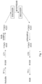
- FIG. 1 An example of traditional processing of HDR video is shown in Fig. 1 .
- TF -1 such as the opto-electrical transfer function (OETF), which is typically the inverse of the electro-optical transfer function (EOTF)
- OETF opto-electrical transfer function
- EOTF electro-optical transfer function
- CT1 first color transform or color transformation
- the chroma components Cb, Cr are subsampled, for instance to quarter resolution resulting in Y'CbCr 4:2:0 or half resultion resulting in Y'CbCr 4:2:2.
- This Y'CbCr 4:2:0 or 4:2:2 color is then input to an encoder to get an encoded representation of the HDR video sequence, typically denoted bitstream in the art.
- the bitstream is then decoded by a decoder to get a reconstructed Y'CbCr 4:2:0 or 4:2:2 color.
- An inverse of the above described processing takes place to upsample the chroma components Cb, Cr to full resolution, giving Y'CbCr 4:4:4.
- a reconstructed R'G'B' color is obtained by applying a second color transform (CT2) onto the reconstructed Y'CbCr 4:4:4 color.
- CT2 second color transform
- This reconstructed R'G'B' color is input to a transfer function (TF), such as the EOTF, to get a reconstructed linear RGB color.
- TF transfer function
- One way to solve this problem is to find the luma value (Y') that will give the correct luminance (Yo), where the luminance Yo is determined by applying a color transform to the original linear RoGoBo color.
- a disadvantages with using binary search is that the number of iterations can vary. As an example, if 10 bits are used, then up to ten iterations are needed to reduce the interval in the binary search.
- the interval reducing method in [1] works by finding a mathematical bound on Y'. As an example, if the lower bound of Y' is 324 and the upper bound of Y' is 455, then the interval [321, 448] can be used in the binary search instead of the full interval [0, 1023]. Since this interval is only 127 steps wide, it will be ready in seven (127 ⁇ 2 7 ) iterations instead of ten. Using such techniques it is possible to get the average number of iterations down to less than two iterations. This means that it can be efficiently used for offline or non-real-time applications, when the average processing time is what counts. However, for real-time applications, it is typically necessary to know in advance how many iterations will take place.
- the claimed embodiments reduce the risk of severe artifacts in pictures as a result, for example, of using a linearization strategy for approximating a transfer function during processing of pixels.
- the present embodiments generally relate to processing of pixels in a picture, and in particular to such processing that improves luminance values of pixels.
- R is obtained from the nonlinear value R' by applying the transfer function tf( ), which can be the PQ-EOTF transfer function as defined by SMPTE ST 2084, or another transfer function, such as BT.1886 or Hybrid Log Gamma (HLG).
- tf( ) can be the PQ-EOTF transfer function as defined by SMPTE ST 2084, or another transfer function, such as BT.1886 or Hybrid Log Gamma (HLG).
- the first term wR ⁇ tf( Y' + a13 ⁇ Cr) can be approximated as a line k1 ⁇ Y' + m1 by linearizing tf(x) ⁇ tf(a) + tf'(a) ⁇ (x-a).
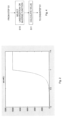
- Fig. 2 shows the behavior of the PQ EOTF as defined by SMPTE ST 2084. The output increases between 0 and 1.0, but after 1.0 the output is capped at 10,000.
- the linear approximation breaks down since the blue channel saturates.
- the optimum luma value Y' i.e., the Y' value that will create a luminance value Y closest to the original luminance value Yo, will make the blue channel saturate.
- a color space or color format is the type and number of colors that originate from the combinations of color components of a color model.
- a color model is an abstract configuration describing the way colors can be represented as tuples of numbers, i.e., color components.
- the color components have several distinguishing features such as the component type, e.g., hue, and its unit, e.g., degrees or percentages, or the type of scale, e.g., linear or non-linear, and its intended number of values referred to as the color depth or bit depth.
- Non-limiting, but illustrative, color spaces that are commonly used for pixels in pictures and videos include the red, green, blue (RGB) color space, the luma, chroma blue and chroma red (Y'CbCr, sometimes denoted YCbCr, Y'Cb'Cr', YCBCR, Y'CBCR or Y'CB'CR') color space and the luminance and chrominances (XYZ) color space.
- RGB red, green, blue
- Y'CbCr sometimes denoted YCbCr, Y'Cb'Cr', YCBCR, Y'CBCR or Y'CB'CR'
- XYZ luminance and chrominances
- the present embodiments thereby obtain a value of the color component using different functions or LUTs depending on whether the optimal value of the color component, i.e., the value that results in the smallest error between the at least one color component in the another color space and the at least one original color component of the pixel in the another color space, causes any color channel of the pixel to fall outside of an allowed range.
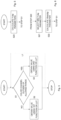
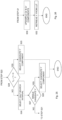
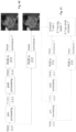
- the processing of a pixel is preferably performed for multiple, i.e., at least two, pixels in the picture as schematically illustrated by the line L1 in Fig. 3 .
- the processing of Fig. 3 could be performed for each pixel in the picture, or at least for a portion thereof.
- the picture is preferably a picture of a video sequence, and in particular an HDR video sequence. In such a case, the method of processing could be performed for pixels in multiple pictures of the (HDR) video sequence.
- step S1 comprises checking whether a color component of the pixel in a second color space resulting in a smallest error between i) a color component in a third color space determined based on the color component in the second color space and an original color component in the third color space determined based on original color components of the pixel in a first color space, or ii) color components in the first color space determined based on the color component in the second color space and the original color components in the first color space causes any color channel of the pixel to fall outside of the allowed range.
- a second function Y' (Yo - wB ⁇ 10000 - wR ⁇ tf(Ro') - wR ⁇ tf'(Ro')(a13 ⁇ Cr - Ro') - wG ⁇ tf(Go') - wG ⁇ tf'(Go')(-a22 ⁇ Cb - a23 ⁇ Cr - Go')) / (wR ⁇ tf'(Ro')+wG ⁇ tf'(Go')) should be used to calculate the value of the luma component (Y').
- the error between the luminance values or the red, green and blue components could be defined in various ways. For instance, an error between the luminance Y determined based on the luma component Y' and the original luminance Yo determined based on the original red, green and blue components Ro, Go, Bo could be defined as
- the error between the red, green and blue components R, G, B determined based on the luma component Y' and the original red, green and blue components Ro, Go, Bo could be defined as
- step S1 comprises checking whether the color component in the color space resulting in the smallest error causes any color channel of the pixel to cause clipping of any color channel of the pixel.
- Clipping is a function well known within computer science and involves replacing the value of a parameter exceeding a maximum value with the maximum value or falling below a minimum value with the minimum value.
- the clipping function could be defined as clip(a, L, U), which outputs L if a ⁇ L, U if a>U and otherwise a.
- a color component causing clipping implies that the value of the color component is outside of the allowed range and is replaced by the maximum or minimum value of the allowed range.
- step S1 comprises checking whether the color component in the color space, preferably luma component Y' in the Y'CbCr color space, resulting in the smallest error causes clipping of any color channel, preferably any of the red, green and blue color channel, of the pixel against zero or one.
- the allowed range is thereby (0, 1).
- zero is the minimum allowed value and one is the maximum allowed value.
- step S1 comprises checking whether the color component in the color space resulting in the smallest error causes any color channel of the pixel to be larger than one or to be smaller than zero, or be equal to or larger than one or to be equal to or smaller than zero. This means that if the color component is ⁇ 0 or ⁇ 1 or ⁇ 0 or >1 then the method continues from step S1 in Fig. 3 to step S3. Otherwise the method continues from step S1 to step S2.
- step S1 comprises checking whether the color component in the color space resulting in the smallest error causes any color channel of the pixel to saturate.
- a color channel saturates if it exceeds the upper limit or maximum value for which the first function or LUT is valid.
- step S2 of Fig. 3 comprises calculating the value of the color component in the color space using a first linearization function if the color component in the color space does not cause any color channel of the pixel to fall outside of the allowed range.
- step S3, correspondingly, comprises in this embodiment, calculating the value of the color component in the color space using a second, different linearization function or an inverse function if the color component in the color space causes any color channel of the pixel to fall outside of the allowed range.
- a first linearization function of the PQ EOTF, or another transfer function is used for function input values below one and another linearization function or an inverse function of the PQ EOTF, or the other transfer function, is used for function input values above one.
- IF RG (.), IF RB (.) and IF GB (.) depending on whether the red and green color channels fall outside of the allowed range, the red and blue color channels fall outside of the allowed range or the green and blue color channels fall outside of the allowed range.
- One idea behind the embodiments is to find out whether the individual color channels, i.e., red, green or blue, saturates to the maximum allowed value before linearizing. As an example, if it can be determined that the Y' that results in the best Y, i.e., closes to Yo, means that the red channel will saturate, it is important that the linearization of the transfer function for that channel will be a constant, instead of a sloping line. This will avoid large errors.
- Y' -(wR ⁇ tf'(Ro')(a13 ⁇ Cr - Ro') + wG ⁇ tf'(Go')(-a22 ⁇ Cb - a23 ⁇ Cr - Go') + wB ⁇ tf'(Bo')(a32 ⁇ Cb - Bo')) / (wR ⁇ tf'(Ro') + wG ⁇ tf'(Go') + wB ⁇ tf'(Bo')).
- Yo on the other hand is larger than Yfirstclip, we cannot use the above formula for calculating Y'*, but must use one that takes into account that one or more of the channels are clipped.
- step S1 of Fig. 3 comprises checking whether a luma component Y' of the pixel resulting in a smallest error between a luminance Y determined based on the luma component Y' and an original luminance Yo determined based on original red, green and blue color components RoGoBo of the pixel causes any of a red, green and blue color channel of the pixel to clip against one, i.e., saturate or is equal to or exceed one.
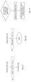
- the method also comprises an additional step S20 as shown in Fig. 5 .
- the method then continues to step S1 in Fig. 3 .
- step S1 comprises checking whether the luma component Y' resulting in the smallest error causes any of the red, green and blue color channel of the pixel to clip against one based on a smallest value of Y'redclip, Y'greenclip and Y'blueclip.
- Fig. 6 is a flow chart illustrating additional steps of the method shown in Fig. 5 .
- the method continues from step S20 in Fig. 5 to step S21 in Fig. 6 .
- step S1 in Fig. 3 .
- This step S1 comprises, in this embodiment, checking whether Yo ⁇ Yfirstclip. If Yo is smaller than Yfirstclip, the method continues to step S2, where the value of the luma component is calculated using a first linearization function as described above. If Yo is not smaller than Yfirstclip then another linearization function or an inverse function should be used and the method continues to step S3 of Fig. 3 or step S10 of Fig. 4 .
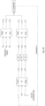
- Fig. 7 is a flow chart illustrating additional steps of the method shown in Fig. 6 .
- the method continues from step S22 in Fig. 6 .
- a next optional step S23 comprises checking whether Yo ⁇ Yfirstclip. If Yo ⁇ Yfirstclip the method continues to step S27, which comprises determining that the luma component Y' resulting in the smallest error does not cause any of the red, green or blue color channel of the pixel to clip, such as clip against one, saturate or be (equal to or) exceed one.
- step S2 in Fig.
- Yo is not smaller than Yfirstclip in step S23, the method continues to step S24.
- the method continues to the optional step S26, which comprises checking whether Yo ⁇ Ysecondclip.
- step S28 comprises determining that the luma component Y' resulting in the smallest error causes one of the red, green and blue color channels of the pixel to clip.
- steps S21 to S23 in Fig. 24 are performed for different candidate non-linear luma component values in the second color space, which is schematically illustrated by the line L2.
- step S2 preferably comprises selecting the candidate non-linear luma component value among the different candidate non-linear luma component values in the second color space that results in a smallest difference between the original linear luminance component value in the third color space and the linear luminance component value in the third color space or a smallest difference between a function of the original linear luminance component value in the third color space and a function of the linear luminance component value in the third color space.
- Another variant is to use two or more neighboring values of Cb' and Cr' and use them directly to calculate the range of possible Cb' and Cr' values.
- an embodiment is to do a binary search to find the best Y' value.
- the maximum Y' value is tried, for instance 1023.
- the minimum Y' value is tried, for instance 0.
- We then proceed by calculating a new value in the middle of the selected interval, and proceeds until the interval only contains a single number, such as [363, 363], or [363, 364]. This is guaranteed to only take log 2 (N) steps, where N is the number of possible values, which in this case is 1024. Hence only log 2 (1024) 10 steps are sufficient.
- Gradient descent can be slow, so a quicker way may be to use a second-order optimization algorithm that calculates or approximates the second order derivatives d 2 E/dY' 2 .
- Gauss-Newton is an example of such an algorithm.
- the Y' values of all pixels in an image or picture are corrected.
- only pixels that are at risk of having visible luminance errors are corrected. This may include pixels that are close to the color gamut edge, but exclude pixels closer to the middle of the color gamut triangle.
- Some linearizations may also be done in advance. As noticed above, the worst problems occur on the gamut edge. Hence one could have one linearization for the line connecting the red primary to the green primary, one linearization for the line connecting the red primary to the blue primary and one linearization for the line connecting the green primary to the blue primary. Another way may be to have linearizations that will be used close to the red primary, another close to the green primary, and a third that is used close to the blue primary. Furthermore it is possible to have several linearizations along the line of the gamut, as shown in Fig. 30 .
- a look-up-table is used for deriving the value of Y'.
- the look-up-table contains every possible value of Y O , Cb' and Cr'. For 10 bit video that will result in 1024 ⁇ 1024 ⁇ 1024 entries and in some applications this size is acceptable.
- the look-up-table (LUT) is pruned, for example through rounding one or more of Y O , Cb' and Cr', e.g., to 8 bits. If a pruned look-up-table is used the algorithm can be extended with a refinement step that finds the best Y' starting from the Y' that was retrieved from the LUT.
- the LUT is only used when the Cb' value and/or the Cr' value is such that Y' can become too different from Y O , i.e., when the initially calculated Y' gives a linear Y value that is too different from Y O , and thereby the size of the LUT can be substantially reduced since many values of Cb' and Cr' will not cause any problems.
- a function of Y O , Cb' and Cr' e.g., a linear combination, polynomial function, exponential function, logarithmic function, trigonometric function, etc., is used for deriving Y'.
- the function can be defined such that for any value of Y O , Cb' and Cr' the difference between Y and Y O is below a certain threshold or the difference between the derived Y' and the optimal Y' is below a certain threshold.
- Y O , Cb' and Cr' are defined for deriving Y'.
- the selection of which function to use is based on the value of Y O , Cb' and Cr'.
- a method is provided as illustrated in Fig. 31 .
- the method can be performed in an encoder or in a pre-process to the encoder.
- a corrected Y' component is derived to compensate for the errors in the Cb' and/or the Cr' components.
- the method optionally also comprise encoding video with the corrected Y' component.
- Another aspect of the embodiments relates to a device for pre-processing a pixel in a picture.
- the device is configured to obtain an original linear luminance component value of the pixel in a third color space determined based on a linear color of the pixel in a first color space.
- the device is also configured to derive a non-linear luma component value in a second color space for the pixel based on a first non-linear chroma component value in the second color space, a second non-linear chroma component value in the second color space and the original linear luminance component value in the third color space.
- the device is configured to determine the original linear luminance component value in the third color space based on the linear color in the first color space.
- the device is configured to derive a non-linear luma component value in the second color space that minimizes a difference between the original linear luminance component value in the third color space and a linear luminance component value in the third color space determined based on the non-linear luma component value in the second color space, the first non-linear chroma component value in the second color space and the second non-linear chroma component value in the second color space.
- the device is configured to derive the non-linear luma component value in the second color space based on a subsampled first non-linear chroma component value in the second color space, a subsampled second non-linear chroma component value in the second color space and the original linear luminance component value in the third color space.
- the device is configured to apply a first transfer function to the original linear color in the first color space to get a non-linear color in the first color space.
- the device is also configured to apply a first color transform to the non-linear color in the first color space to get a non-linear color in the second color space.
- the non-linear color in the second color space comprises an initial first non-linear chroma component value and an initial second non-linear chroma component value.
- the device is further configured to subsample the initial first non-linear chroma component value in the second color space and the initial second non-linear chroma component value in the second color space to get the subsampled first non-linear chroma component value in the second color space and the subsampled second non-linear chroma component value in the second color space.
- the device is configured to upsample the subsampled first non-linear chroma component value in the second color space and the subsampled second non-linear chroma component value in the second color space to get an upsampled first non-linear chroma component value in the second color space and an upsampled second non-linear chroma component value in the second color space.
- the device is also configured to apply a second color transform to a candidate non-linear luma component value in the second color space, the upsampled first non-linear chroma component value in the second color space and the upsampled second non-linear chroma component value in the second color space to get a non-linear color in the first color space.
- the device is further configured to apply a second transfer function to the non-linear color in the first color space to get a linear color in the first color space.
- the device is additionally configured to apply a third color transform to the linear color in the first color space to get a linear luminance component value in the third color space.
- the device is also configured to derive the non-linear luma component value based on a comparison of the original linear luminance component value in the third color space and the linear luminance component value in the third color space.
- the device is configured to select a candidate non-linear luma component in the second color space that reduces, such as minimizes, a difference between the original linear luminance component in the third color space and the linear luminance component in the third color space.
- the device is configured to perform application of the second color transform to a candidate non-linear luma component value in the second color space, the upsampled first non-linear chroma component value in the second color space and the upsampled second non-linear chroma component value in the second color space, application of the second transfer function to the non-linear color in the first color space and application of the third color transform to the linear color in the first color space for different candidate non-linear luma component values in the second color space.
- the device is also configured to select the candidate non-linear luma component value among the different candidate non-linear luma component values in the second color space that results in a smallest difference between the original linear luminance component value in the third color space and the linear luminance component value in the third color space.
- the device is configured to perform a binary search to select a candidate non-linear luma component value in the second color space that minimizes a difference between the original linear luminance component value in the third color space and the linear luminance component value in the third color space.
- the device is configured to perform application of the second color transform to a candidate non-linear luma component value in the second color space, the upsampled first non-linear chroma component value in the second color space and the upsampled second non-linear chroma component value in the second color space, application of the second transfer function to the non-linear color in the first color space and application of the third color transform to the linear color in the first color space for a candidate non-linear luma component value in the second color space in the middle of a search interval.
- the device is also configured to select the candidate non-linear luma component value in the middle of the search interval if the difference between the original linear luminance component value in the third color space and the linear luminance component value in the third color space is equal to zero.
- the device is also configured to otherwise select a search interval having half the size as compared to the search interval used by the device when performing the applications and ending at the candidate non-linear luma component value used by the device when performing the applications if the linear luminance component value in the third color space is larger than the original linear luminance component value in the third color space or select a search interval having half the size as compared to the search interval used by the device when performing the applications and starting at the candidate non-linear luma component value used by the device when performing the applications if the linear luminance component value in the third color space is smaller than the original linear luminance component value in the third color space.
- the device is further configured to repeat performing the applications and selection of the search interval until the difference between the original linear luminance component value in the third color space and the linear luminance component value in the third color space is equal to zero or the search interval comprises a single candidate non-linear luma component value in the second color space.
- the device is configured to upsample the subsampled first non-linear chroma component value in the second color space and the subsampled second non-linear chroma component value in the second color space to get an upsampled first non-linear chroma component value in the second color space and an upsampled second non-linear chroma component value in the second color space.
- the device is also configured to retrieve the non-linear luma component value in the second color space from a look-up table using the original linear luminance component value in the third color space, or a non-linear version thereof, the upsampled first non-linear chroma component value in the second color space and the upsampled second non-linear chroma component value in the second color space, or quantized versions thereof, as input to the look-up table.
- the device is configured to apply the first transfer function to the original linear luminance component value in the third color space to get an original non-linear luminance component value in the third color space.
- the device is configured to retrieve the non-linear luma component value in the second color space from the look-up table using the original non-linear luminance component value in the third color space, the upsampled first non-linear chroma component value in the second color space and the upsampled second non-linear chroma component value in the second color space, or the quantized versions thereof, as input to the look-up table.
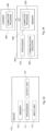
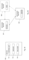
- Fig. 32 illustrates a particular hardware implementation of a device 100 for pre-processing a picture according to an embodiment.
- the device 100 comprises a determining unit 101 configured to obtain the original linear luminance component value of the pixel in the third color space.
- the device 100 also comprises a deriver 102 configured to derive the non-linear luma component value in the second color space for the pixel.
- the device 100 comprises a determining unit 101 configured to determine that Cb' and/or Cr' include errors.
- the device 100 also comprises a deriver 102 configured to derive a corrected Y'.
- the device 100 further comprises a video encoder 103 configured to encode a picture with the corrected Y'.
- the device 100 also comprises an input unit 104 configured to receive the video to be encoded and an output unit 105 configured to output an encoded bitstream.
- the input unit 104 could be in the form of a general input unit, in particular in the case of a wired connection to external devices.
- the input unit 104 could be in the form of a receiver or transceiver, in particular in the case or a wireless connection to external devices.
- the output unit 105 could be in the form of a general output unit, in particular in the case of a wired connection to external devices.
- the output unit 105 could be in the form of a transmitter or transceiver, in particular in the case or a wireless connection to external devices
- the input unit 104 is preferably connected to the determining unit 101, the deriver 102 and the video encoder 103 to forward the video to be encoded thereto.
- the determining unit 101 is preferably connected to the deriver 102 and the video encoder 103.
- the video encoder 103 is preferably connected to the output unit 105 to forward the encoded bitstream to, for instance, a decoder.
- suitable hardware circuitry include one or more suitably configured or possibly reconfigurable electronic circuitry, e.g., Application Specific Integrated Circuits (ASICs), Field Programmable Gate Arrays (FPGAs), or any other hardware logic such as circuits based on discrete logic gates and/or flip-flops interconnected to perform specialized functions in connection with suitable registers (REG), and/or memory units (MEM).
- ASICs Application Specific Integrated Circuits
- FPGAs Field Programmable Gate Arrays
- REG registers
- MEM memory units
- At least some of the steps, functions, procedures, modules and/or blocks described herein may be implemented in software such as a computer program for execution by suitable processing circuitry such as one or more processors or processing units.
- processing circuitry includes, but is not limited to, one or more microprocessors, one or more Digital Signal Processors (DSPs), one or more Central Processing Units (CPUs), video acceleration hardware, and/or any suitable programmable logic circuitry such as one or more FPGAs, or one or more Programmable Logic Controllers (PLCs).
- DSPs Digital Signal Processors
- CPUs Central Processing Units
- PLCs Programmable Logic Controllers
- the device 110 comprises a processor 111 and a memory 112 comprising instructions executable by the processor 111.
- the processor 111 is operative to obtain the original linear luminance component value of the pixel in the third color space.
- the processor 111 is also operative to derive the non-linear luma component value in the second color space for the pixel.
- the processor 111 is operative to determine that the Cb' and/or Cr' components include errors and when it is determined that the Cb' and/or Cr' components include errors.
- the processor 111 is also operative to derive a corrected Y' component to compensate for the errors in the Cb' and/or the Cr' components.
- the device 110 also comprises an input unit 113 configured to receive the video to be encoded.
- the processor 111 is operative to receive the video to be encoded from the input unit 113.
- the device 110 also comprises an output unit 114 configured to output an encoded bitstream as received from the processor 111.
- the processor 111 is operative, when executing the instructions stored in the memory 112 to perform the above described operations.
- the processor 111 is thereby interconnected to the memory 112 to enable normal software execution.
- Fig. 34 is a schematic block diagram illustrating an example of a user equipment (UE) 200 comprising a processor 210, an associated memory 220 and a communication circuitry 230.
- UE user equipment
- a computer program 240 which is loaded into the memory 220 for execution by processing circuitry including one or more processors 210.
- the processor 210 and memory 220 are interconnected to each other to enable normal software execution.
- a communication circuitry 230 is also interconnected to the processor 210 and/or the memory 220 to enable input and/or output of video data.
- the user equipment 200 can be any device or apparatus that can receive and process video data.
- the user equipment 200 could be a computer, either stationary or portable, such as laptop, a smart phone, a tablet, a set-top box, a video camera, etc.
- processor' should be interpreted in a general sense as any system or device capable of executing program code or computer program instructions to perform a particular processing, determining or computing task.
- the processing circuitry including one or more processors is thus configured to perform, when executing the computer program, well-defined processing tasks such as those described herein.
- the processing circuitry does not have to be dedicated to only execute the above-described steps, functions, procedure and/or blocks, but may also execute other tasks.
- the computer program 240 comprises instructions, which when executed by the processor 210, cause the processor 210 to determine that the Cb' and/or Cr' components include errors, and when it has determined that the Cb' and/or Cr' components include errors, they cause the processor 210 to derive a corrected Y' component to compensate for the errors in the Cb' and the Cr' components.
- a further aspect of the embodiments also relates to a signal representing an encoded version of a pixel in a picture.
- the encoded version comprises an encoded version of a subsampled first non-linear chroma component value in a second color format, an encoded version of a subsampled second non-linear chroma component value in the second color format and an encoded version of a non-linear luma component value in the second color format derived according to any of the embodiments.
- the signal is one of an electronic signal, an optical signal, an electromagnetic signal, a magnetic signal, an electric signal, a radio signal and a microwave signal.
- a corresponding device may be defined as a group of function modules, where each step performed by the processor corresponds to a function module.
- the function modules are implemented as a computer program running on the processor.
- the device may alternatively be defined as a group of function modules, where the function modules are implemented as a computer program running on at least one processor.
- the computer program residing in memory may thus be organized as appropriate function modules configured to perform, when executed by the processor, at least part of the steps and/or tasks described herein.
- An example of such function modules is illustrated in Fig. 35 .
- Fig. 35 is a schematic block diagram of a device 120 for pre-processing a pixel in a picture with function modules.
- the device 120 comprises a determining unit 121 for obtaining an original linear luminance component value of the pixel in a third color space determined based on a linear color of the pixel in a first color space.
- the device 120 also comprises a deriver 122 for deriving a non-linear luma component value in a second color space for the pixel based on a first non-linear chroma component value in the second color space, a second non-linear chroma component value in the second color space and the original linear luminance component value in the third color space.
- the device 120 comprises a determining unit 121 for determining that Cb' and/or Cr' include errors.
- the device 120 also comprises a deriver 102 for deriving a corrected Y'.
- the device 120 further, optionally, comprises a video encoder 123 for encoding the bitstream using the corrected Y'.
- a further aspect of the embodiments relates to a device 110 for encoding a pixel in a picture.
- the device 110 comprises a processor 111 and a memory 112 comprising instructions executable by the processor 111.
- the processor 111 is operative to obtain an original linear luminance component value of the pixel in a third color space determined based on a linear color of the pixel in a first color space.
- the processor 111 is also operative to derive a non-linear luma component value in a second color space for the pixel based on a first non-linear chroma component value in the second color space, a second non-linear chroma component value in the second color space and the original linear luminance component value in the third color space.
- the processor 111 is further operative to encode the non-linear luma component value, the first non-linear chroma component value and the second non-linear chroma component value.
- the device 120 comprises a determining unit 121 for obtaining an original linear luminance component value of the pixel in a third color space determined based on a linear color of the pixel in a first color space.
- the device 120 also comprises a deriver 122 for deriving a non-linear luma component value in a second color space for the pixel based on a first non-linear chroma component value in the second color space, a second non-linear chroma component value in the second color space and the original linear luminance component value in the third color space.
- the device 120 further comprises an encoder 123 for encoding the non-linear luma component value, the first non-linear chroma component value and the second non-linear chroma component value.
- a unit such as a pre-processor or an encoder.
- the unit is configured to determine that the Cb' and/or Cr' components include errors, and when it has determined that the Cb' and/or Cr' components include errors, it is configured to derive a corrected Y' component to compensate for the errors in the Cb' and the Cr' components.
- the present embodiments also relates to a user equipment comprising a device for pre-processing a pixel or a device for encoding a pixel according to the embodiments.
- the user equipment is preferably a device or apparatus configured to receive and process video data.
- the user equipment could, for instance, be a device or apparatus configured to forward video data over an interface, such as HDMI.
- a user equipment comprising a device for pre-processing a pixel or a device for encoding a pixel according to the embodiments.
- the user equipment is preferably selected from a group consisting of a computer, a laptop, a smart phone, a tablet and a set-top box.
- computing services such as hardware and/or software
- network devices such as network nodes and/or servers
- functionality can be distributed or re-located to one or more separate physical nodes or servers.
- the functionality may be re-located or distributed to one or more jointly acting physical and/or virtual machines that can be positioned in separate physical node(s), i.e., in the so-called cloud.
- cloud computing is a model for enabling ubiquitous on-demand network access to a pool of configurable computing resources such as networks, servers, storage, applications and general or customized services.
- Fig. 36 is a schematic diagram illustrating an example of how functionality can be distributed or partitioned between different network devices 300, 301, 302 in a general case.
- the network devices 300, 301, 302 may be part of the same wireless communication system, or one or more of the network devices may be so-called cloud-based network devices located outside of the wireless communication system.
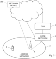
- Fig. 37 is a schematic diagram illustrating an example of a wireless communication system, including an access network 1 and/or a core network 2 and/or an Operations and Support System (OSS) 3 in cooperation with one or more cloud-based network devices 300.
- the figure also illustrates a network node 4 of the access network 1 and a user equipment 5 according to the embodiments.
- OSS Operations and Support System
- High dynamic range (HDR) video uses another way to increase perceived image quality, namely by increasing contrast.
- the conventional TV system was built for luminances between 0.1 candela per square meter (cd/m 2 ) and 100 cd/m 2 , or about ten doublings of luminance, this is generally referred to as standard dynamic range (SDR) video.
- SDR standard dynamic range
- some HDR monitors are capable of displaying a range from 0.01 to 4000 cd/m 2 , i.e., over 18 doublings.
- Typical SDR systems such as TVs or computer monitors often use an eight bit representation where 0 represents dark and 255 bright.
- Just linearly scaling the code value range [0; 255] to the luminance range [0.1; 100] cd/m 2 mentioned above would not be ideal:
- the first two code words 0 and 1 would be mapped to 0.1 cd/m 2 and 0.49 cd/m 2 respectively, a relative difference of 390 %.
- the last two code words 254 and 255 on the other hand, would be mapped to 99.61 cd/m 2 and 100 cd/m 2 respectively, a relative difference of only 0.3 %.
- SDR systems include an electro-optical transfer function (EOTF) which maps code values to luminances in a non-linear way.
- EOTF electro-optical transfer function
- R' is scaled to the range [0.1; 100] to get the light representation in cd/m 2 .
- the green and blue components are handled in the same way.
- a video encoder such as HEVC encoder.
- the HEVC bitstream is decoded to recover (Y' 420 , Cb' 420 , Cr' 420 ) or rather decoded versions of these values due to the fact that HEVC is a lossy decoder.
- the signal is then processed in reverse to what is described above. The end result is the linear light representation (R, G, B), which is displayed.
- This Annex B investigates color artifacts due to 4:2:0 subsampling.
- Table B7 data for the "worst" color for 4:2:0 subsampling if input is P3 and container format is BT.2020 pixel 97 RGB value Y value Y diff relative error Barten steps original P3 color 3.29 0 6.71 original BT.2020 color 2.7993 1.2853 0.2342 6.5960 RGB 4:4:4 2.8099 1.2788 0.0065 0.5062 % 0.5951 0.2304 6.4838 RGB 4:2:0 1.4911 0.8438 0.4416 34.3530 % 40.38 0.3834 3.2402
Landscapes
- Engineering & Computer Science (AREA)
- Multimedia (AREA)
- Signal Processing (AREA)
- Physics & Mathematics (AREA)
- Computer Hardware Design (AREA)
- General Physics & Mathematics (AREA)
- Theoretical Computer Science (AREA)
- Image Processing (AREA)
- Color Image Communication Systems (AREA)
- Processing Of Color Television Signals (AREA)
- Facsimile Image Signal Circuits (AREA)
Claims (17)
- Procédé de traitement d'un pixel d'une image, ledit pixel étant défini par des composantes de couleur d'origine dans un premier espace colorimétrique, le procédé comprenant :la vérification (S1) si une composante de couleur dudit pixel dans un deuxième espace colorimétrique résultant en la plus petite erreur entre i) une composante de couleur dans un troisième espace colorimétrique déterminée sur la base de ladite composante de couleur dans ledit deuxième espace colorimétrique et une composante de couleur d'origine correspondante dudit pixel dans ledit troisième espace colorimétrique déterminée sur la base desdites composantes de couleur d'origine dans ledit premier espace colorimétrique ou entre ii) une composante de couleur dans ledit premier espace colorimétrique déterminée sur la base de ladite composante de couleur dans ledit deuxième espace colorimétrique et une composante de couleur d'origine correspondante dans ledit premier espace colorimétrique, amène tout canal de couleur dudit pixel à tomber en dehors d'une plage autorisée ;l'obtention (S2) d'une valeur de ladite composante de couleur dans ledit deuxième espace colorimétrique à l'aide d'une première fonction ou d'une première table de consultation si ladite composante de couleur dans ledit second espace colorimétrique résultant de ladite plus petite erreur ne fait tomber aucun canal de couleur dudit pixel en dehors de ladite plage autorisée ; etl'obtention (S3) d'une valeur de ladite composante de couleur dans ledit deuxième espace de couleur en utilisant une deuxième fonction différente ou une deuxième table de consultation différente si ladite composante de couleur dans ledit deuxième espace de couleur résultant de ladite plus petite erreur amène tout canal de couleur dudit pixel à tomber en dehors de ladite plage autorisée.
- Procédé selon la revendication 1, dans lequel :les composants de couleur d'origine définissant ledit pixel dans ledit premier espace colorimétrique comprennent des composants de couleur rouge, vert et bleu, R0G0B0 ;les composantes de couleur définissant ledit pixel dans ledit deuxième espace colorimétrique comprennent les composantes de couleur de luminance et de chrominance, Y'CbCr, ladite composante de couleur dans ledit deuxième espace colorimétrique comprenant la composante de couleur de luminance, Y' ; etla composante de couleur dans ledit troisième espace colorimétrique est une composante de luminance, Y.
- Procédé selon l'une quelconque des revendications 1 à 2, dans lequel ladite vérification (S1) comprend la vérification (S1) si la composante de couleur dudit pixel dans ledit second espace de couleur résultant de ladite plus petite erreur provoque l'écrêtage de tout canal de couleur dudit pixel.
- Procédé selon l'une quelconque des revendications 1 à 3, dans lequel ladite vérification (S1) comprend la vérification (S1) si la composante de couleur dudit pixel dans ledit second espace de couleur résultant de ladite plus petite erreur provoque tout canal de couleur dudit pixel à être supérieur à un ou inférieur à zéro.
- Procédé selon l'une quelconque des revendications 1 à 4, dans lequel ladite vérification (S1) comprend la vérification (S1) si la composante de couleur dudit pixel dans ledit deuxième espace de couleur résultant de ladite plus petite erreur provoque la saturation de tout canal de couleur dudit pixel.
- Procédé selon l'une quelconque des revendications 1 à 5, comprenant en outre :
l'obtention (S3) de ladite valeur de ladite composante de couleur pour ledit pixel dans ledit deuxième espace colorimétrique en utilisant une fonction inverse comprenant un inverse d'une fonction de transfert respective utilisée pour convertir les valeurs desdites composantes de couleur dans ledit deuxième espace colorimétrique en valeurs pour les composantes de couleur dans ledit premier espace colorimétrique si la composante de couleur dudit pixel dans ledit deuxième espace colorimétrique résultant de ladite plus petite erreur amène tout canal de couleur dudit pixel à tomber en dehors de ladite plage autorisée,. - Procédé selon la revendication 6, dans lequelladite vérification (S1) comprend la vérification (S1) si une valeur de composante de luminance Y' pour ledit pixel dans ledit deuxième espace colorimétrique résultant en la plus petite erreur entre une valeur de luminance Y déterminée pour ledit pixel dans ledit troisième espace colorimétrique sur la base de ladite valeur de composante de luminance Y' et des valeurs de composante de chrominance calculées Cb, Cr pour ledit pixel dans ledit deuxième espace colorimétrique, et une valeur de luminance d'origine Y0 déterminée pour ledit pixel dans ledit troisième espace colorimétrique sur la base desdites valeurs de composante de couleur rouge, verte et bleue d'origine R0G0B0 définissant ledit pixel dans ledit premier espace colorimétrique, provoque l'écrêtage de l'une quelconque des valeurs de composante de couleur rouge, verte et bleue déterminées pour ledit pixel dans ledit premier espace colorimétrique à l'aide de ladite valeur de composante de luminance Y' et desdites valeurs de composante de chrominance Cb, Cr pour ledit pixel dans ledit deuxième espace colorimétrique ;l'obtention (S2) de ladite valeur de ladite composante de luminance Y' pour ledit pixel dans ledit second espace colorimétrique comprend le calcul (S2) d'une valeur de ladite composante de luminance Y' comme
 si ladite valeur de composante de luminance Y' dans ledit deuxième espace colorimétrique résultant de ladite plus petite erreur ne provoque l'écrêtage d'aucune desdites valeurs de composante de couleur rouge, verte ou bleue déterminées pour ledit pixel dans ledit premier espace colorimétrique, où WR, WG, WB désignent les poids de couleur, a 13, a 22, a 23, a 32 désignent les constantes positives d'une transformation de couleur d'une couleur Y'CbCr à une couleur R'G'B', Cb, Cr désignent lesdites valeurs de composante de chrominance dudit pixel dans ledit second espace colorimétrique, P = tf(P'), où P = rouge (R), vert (V) ou bleu (B), tf(.) est une fonction de transfert et tf'(Po') désigne la dérivée de ladite fonction de transfert dans Po' ;la sélection (S10) de ladite seconde fonction de linéarisation différente ou de ladite fonction inverse comprend :la sélection de ladite seconde fonction de linéarisation différente
 si ladite valeur de composante de couleur rouge déterminée pour ledit pixel dans ledit premier espace colorimétrique écrête :la sélection de ladite seconde fonction de linéarisation différente
 si ladite valeur de composante de couleur verte déterminée pour ledit pixel dans ledit premier espace colorimétrique écrête ;la sélection de ladite seconde fonction de linéarisation différente
 si ladite valeur de composante de couleur bleue déterminée pour ledit pixel dans ledit premier espace colorimétrique écrête ;la sélection de ladite fonction inverse
 si lesdites valeurs de composantes de couleur rouge et verte sont déterminées pour ledit pixel dans ledit premier clip d'espace colorimétrique,dans lequel tf-1(.) désigne l'inverse de ladite fonction de transfert tf(.) ;la sélection de ladite fonction inverse
 si lesdites valeurs de composantes de couleur rouge et bleue déterminées pour ledit pixel dans ledit premier espace colorimétrique écrêtent ; etla sélection de ladite fonction inverse
 si lesdites valeurs de composantes de couleur verte et bleue sont déterminées pour ledit pixel dans ledit premier espace colorimétrique écrêtent.
 - Procédé selon la revendication 7, comprenant en outre le calcul (S20) de Y'redclip = 1-a13Cr, Y'greenclip = 1+a22Cb + a 23 Cr et Y'blueclip = 1-a32Cb, et dans lequel la vérification (S1) si ladite valeur de composante de luminance Y' dudit pixel dans ledit second espace colorimétrique résultant de ladite plus petite erreur provoque l'écrêtage de l'une quelconque desdites valeurs de composante de couleur rouge, verte et bleue déterminées pour ledit pixel dans ledit premier espace colorimétrique comprend la vérification (S1) si ladite valeur de composante de luminance Y' dudit pixel résultant de ladite plus petite erreur provoque l'écrêtage de l'une quelconque desdites valeurs de composante de couleur rouge, verte et bleue déterminées pour ledit pixel dans ledit premier espace colorimétrique sur la base de la plus petite valeur de Y'redclip, Y'greenclip et Y'blueclip.
- Procédé selon la revendication 8, comprenant en outre :la sélection (S21) de la plus petite valeur Y'firstclip = min(Y'redclip, Y'greenclip, Y'blueclip) ; etle calcul (S22) Yfirstclip = wRtf(Y'firstclip + a13Cr) + wG tf(Y'firstclip - a 22 Cb - a23Cr) + wBtf(Y'firstclip + a 32 Cb), dans lequel la vérification (S1) si ladite valeur de composante de luminance Y' dudit pixel dans ledit second espace colorimétrique résultant en ladite plus petite erreur provoque l'écrêtage de l'une quelconque desdites valeurs de composante de couleur rouge, verte et bleue déterminées pour ledit pixel dans ledit premier espace colorimétrique comprend la vérification (S1) si Y0<Yfirstclip.
- Procédé selon la revendication 9, comprenant en outre :la sélection (S24) d'une valeur médiane Y'secondclip = median(Y'redclip, Y'greenclip, Y'blueclip) ; etle calcul (S25) de Ysecondclip = wRtf (Y'secondclip + a13Cr) + wGtf (Y' secondclip - a 22 Cb - a23Cr) + wBtf(Y'secondclip + a32Cb), dans lequel la vérification (S1) si ladite valeur de composante de luminance Y' dudit pixel dans ledit second espace colorimétrique résultant de ladite plus petite erreur provoque l'écrêtage de l'une desdites valeurs de composantes de couleur rouge, verte et bleue déterminées pour ledit pixel dans ledit premier espace colorimétrique comprend :la détermination (S27) que ladite valeur de composante de luminance Y' résultant de ladite plus petite erreur ne provoque pas l'écrêtage d'aucune desdites valeurs de composante de couleur rouge, verte ou bleue déterminées pour ledit pixel dans ledit premier espace colorimétrique si Y0<Yfirstclip ;la détermination (S28) que ladite valeur de composante de luminance Y' résultant de ladite plus petite erreur provoque l'écrêtage de l'une desdites valeurs de composante de couleur rouge, verte et bleue déterminées pour ledit pixel dans ledit premier espace colorimétrique si Yfirstclip≤Y0<Ysecondclip ; et la détermination (S29) que ladite valeur de composante de luminance Y' résultant de ladite plus petite erreur provoque l'écrêtage de deux desdites valeurs de composante de couleur rouge, verte et bleue déterminées pour ledit pixel dans ledit premier espace colorimétrique si Y0≥Ysecondclip.
- Procédé selon l'une quelconque des revendications 1 à 5, dans lequel ladite vérification (S1) comprend la vérification (S1) si une valeur de composante de luminance Y' dudit pixel dans ledit second espace colorimétrique résultant en la plus petite erreur entre l'une quelconque desdites valeurs de composante de couleur rouge, verte et bleue RGB déterminées pour ledit pixel dans ledit premier espace colorimétrique à l'aide desdites valeurs de composante de luminance et de chrominance Y', Cb, Cr, et desdites valeurs de composante de couleur d'origine R0G0B0 respectives pour ledit pixel dans ledit premier espace colorimétrique, provoque l'écrêtage de toute valeur de composante de couleur rouge, verte et bleue déterminée pour ledit pixel dans ledit premier espace colorimétrique, à l'aide desdites valeurs de composante de luminance et de chrominance Y', Cb, Cr dudit pixel dans ledit second espace colorimétrique.
- Procédé selon l'une quelconque des revendications 7 à 11, dans lequel la vérification (S1) pour savoir si la valeur de composante de luminance Y' du pixel dans le second espace colorimétrique, résultant de la plus petite erreur, provoque l'écrêtage de l'une quelconque des valeurs de composante de couleur rouge, verte et bleue déterminées pour le pixel dans le premier espace colorimétrique comprend la récupération (S1), à partir d'une table de consultation, en utilisant comme entrée pour chacune des composantes de couleur rouge, verte et bleue du pixel, la valeur de luminance d'origine Y0 et les valeurs de composante de chrominance Cb, Cr du pixel ou leurs versions quantifiées, un bit indiquant si la valeur de composante de luminance Y' du pixel dans le second espace colorimétrique, résultant de la plus petite erreur, provoque l'écrêtage de la valeur de composante de couleur rouge, verte ou bleue déterminée pour le pixel dans le premier espace colorimétrique.
- Procédé selon l'une quelconque des revendications 1 à 12, comprenant en outre le calcul (S30) de Y'redclipZero = -a 13 Cr, Y'greenclipZero = a 22 Cb + a 23 Cr et Y'blueclipZero = 1 -a32Cb, où a13, a 22, a 23, a32 désignent des constantes positives d'une transformation de couleur d'une couleur Y'CbCr à une couleur R'G'B', Y' désigne une valeur de composante de luminance dudit pixel dans ledit second espace colorimétrique, Cb, Cr désignent des valeurs de composante de chrominance dudit pixel dans ledit second espace colorimétrique, et dans lequel la vérification (S1) si ladite valeur de composante de couleur dudit pixel dans ledit second espace colorimétrique, résultant de ladite plus petite erreur, fait que tout canal de couleur pour ledit pixel se situe en dehors de ladite plage autorisée comprend la vérification (S1) si une valeur de composante de luminance Y' dudit pixel dans ledit second espace colorimétrique, résultant de ladite plus petite erreur entre i), une valeur de luminance Y déterminée pour ledit pixel dans ledit troisième espace colorimétrique sur la base de ladite valeur de composante de luminance Y', et une luminance d'origine Y0 déterminée pour ledit pixel dans ledit troisième espace colorimétrique sur la base de ladite au moins une valeur de composante de couleur d'origine dudit pixel comprenant les valeurs de composantes de couleur rouge, verte et bleue d'origine R0G0B0 définies pour ledit pixel dans ledit premier espace colorimétrique, ou entre ii) les valeurs de composantes de couleur rouge, verte et bleue RGB déterminées pour ledit pixel dans ledit premier espace colorimétrique à l'aide de ladite valeur de composante de luminance Y' et desdites valeurs de composantes de couleur rouge, verte et bleue d'origine R0G0B0 définies pour ledit pixel dans ledit premier espace colorimétrique, provoque l'écrêtage de l'une quelconque des valeurs de composantes de couleur rouge, verte et bleue déterminées pour ledit pixel dans ledit premier espace colorimétrique par rapport à zéro sur la base d'au moins l'un des éléments suivants
Y'redclipZero = -a 13 Cr, Y'greenclipZero = a 22 Cb + a 23 Cr et Y'blueclipZero = 1 -a32Cb. - Procédé selon l'une quelconque des revendications 1 à 5, dans lequell'obtention (S2) de ladite composante de couleur pour ledit pixel dans ledit second espace colorimétrique comprend la récupération (S2) d'une valeur de ladite composante de couleur pour ledit pixel dans ledit second espace colorimétrique à partir d'une première table de consultation si ladite valeur de composante de couleur pour ledit pixel dans ledit second espace colorimétrique n'amène aucun canal de couleur dudit pixel à sortir de ladite plage autorisée ; etl'obtention (S3) de la composante couleur du pixel dans le second espace colorimétrique comprend l'extraction (S3) d'une valeur de ladite composante de couleur à partir d'une table de consultation différente, si ladite composante de couleur déterminée pour ledit pixel dans ledit second espace colorimétrique amène tout canal de couleur à sortir de la plage autorisée, l'extraction (S3) de ladite valeur de ladite composante de couleur du pixel dans ledit second espace colorimétrique comprend :la sélection (S40) de ladite seconde table de consultation différente en fonction du canal de couleur pour ledit pixel qui se situe en dehors de ladite plage autorisée ; etla récupération (S41) de ladite valeur de ladite composante de couleur dudit pixel dans ledit second espace colorimétrique à partir de ladite seconde table de consultation différente sélectionnée.
- Procédé de codage d'un pixel dans une image, ledit procédé comprenant :Le traitement (S1, S2, S3) dudit pixel selon l'une quelconque des revendications 1 à 14 pour dériver une valeur d'une composante de luminance pour ledit pixel dans ledit second espace colorimétrique ; etLe codage (S4) de ladite valeur de ladite composante de luminance pour ledit pixel, et des valeurs de composantes de chrominance sous-échantillonnées déterminées pour ledit pixel dans ledit second espace colorimétrique.
- Dispositif (100, 110, 120, 130) de traitement d'un pixel d'une image, ledit pixel étant défini par des valeurs de composantes de couleur d'origine dans un premier espace colorimétrique, dans lequelledit dispositif (100, 110, 120, 130) étant configuré pour vérifier si une composante de couleur dudit pixel dans un second espace colorimétrique entraînant la plus petite erreur entre i) une composante de couleur dans un troisième espace colorimétrique déterminée sur la base de ladite composante de couleur dans ledit second espace colorimétrique et une composante de couleur d'origine correspondante dudit pixel dans ledit troisième espace colorimétrique déterminée sur la base desdites composantes de couleur d'origine dans ledit premier espace colorimétrique, ou entre ii) une composante de couleur dans ledit premier espace colorimétrique déterminée sur la base de ladite composante de couleur dans ledit second espace colorimétrique et une composante de couleur d'origine correspondante dans ledit premier espace colorimétrique, amène tout canal de couleur dudit pixel à tomber en dehors d'une plage autorisée ;ledit dispositif (100, 110, 120, 130) est configuré pour obtenir une valeur de ladite composante de couleur dudit pixel dans ledit second espace de couleur en utilisant une première fonction ou une première table de consultation si ladite valeur de composante de couleur dans ledit second espace de couleur résultant de ladite plus petite erreur ne fait pas tomber un quelconque canal de couleur dudit pixel en dehors de ladite plage autorisée ;ledit dispositif (100, 110, 120, 130) est configuré pour obtenir une valeur de ladite composante de couleur dudit pixel dans ledit second espace de couleur en utilisant une seconde fonction différente ou une seconde table de consultation différente, si ladite valeur de composante de couleur dans ledit second espace de couleur résultant de ladite plus petite erreur amène tout canal de couleur dudit pixel à tomber en dehors de ladite plage autorisée.
- Programme informatique (240) comprenant des instructions qui, lorsqu'elles sont exécutées par au moins un processeur (210), amènent ledit processeur (210) à traiter un pixel, ledit pixel étant défini par les valeurs des composantes de couleur d'origine dans un premier espace colorimétrique, et à :vérifier si une composante de couleur dudit pixel dans un deuxième espace colorimétrique résultant en la plus petite erreur entre i) une composante de couleur dans un troisième espace colorimétrique déterminée sur la base de ladite composante de couleur dans ledit deuxième espace colorimétrique et une composante de couleur d'origine correspondante dudit pixel dans ledit troisième espace colorimétrique déterminée sur la base desdites composantes de couleur d'origine dans ledit premier espace colorimétrique ou entre ii) une composante de couleur dans ledit premier espace colorimétrique déterminée sur la base de ladite composante de couleur dans ledit deuxième espace colorimétrique et une composante de couleur d'origine correspondante dans ledit premier espace colorimétrique, amène tout canal de couleur dudit pixel à tomber en dehors d'une plage autorisée ;obtenir une valeur de ladite composante de couleur dudit pixel dans ledit second espace colorimétrique en utilisant une première fonction ou une première table de consultation si ladite composante de couleur dans ledit second espace colorimétrique résultant de ladite plus petite erreur ne fait tomber aucun canal de couleur dudit pixel en dehors de ladite plage autorisée ;obtenir une valeur de ladite composante de couleur dudit pixel dans ledit deuxième espace colorimétrique en utilisant une deuxième fonction différente ou une deuxième table de consultation différente si ladite composante de couleur dans ledit deuxième espace colorimétrique résultant de ladite plus petite erreur amène tout canal de couleur dudit pixel à tomber en dehors de ladite plage autorisée.
Applications Claiming Priority (2)
| Application Number | Priority Date | Filing Date | Title |
|---|---|---|---|
| US201662337025P | 2016-05-16 | 2016-05-16 | |
| PCT/SE2016/051146 WO2017200447A1 (fr) | 2016-05-16 | 2016-11-18 | Traitement de pixels à composante de couleurs |
Publications (4)
| Publication Number | Publication Date |
|---|---|
| EP3459256A1 EP3459256A1 (fr) | 2019-03-27 |
| EP3459256A4 EP3459256A4 (fr) | 2019-11-13 |
| EP3459256B1 true EP3459256B1 (fr) | 2025-07-09 |
| EP3459256C0 EP3459256C0 (fr) | 2025-07-09 |
Family
ID=60325420
Family Applications (1)
| Application Number | Title | Priority Date | Filing Date |
|---|---|---|---|
| EP16902562.4A Active EP3459256B1 (fr) | 2016-05-16 | 2016-11-18 | Traitement de pixels à composante de couleurs |
Country Status (5)
| Country | Link |
|---|---|
| US (1) | US10699671B2 (fr) |
| EP (1) | EP3459256B1 (fr) |
| CN (1) | CN109479151B (fr) |
| RU (1) | RU2709652C1 (fr) |
| WO (1) | WO2017200447A1 (fr) |
Families Citing this family (9)
| Publication number | Priority date | Publication date | Assignee | Title |
|---|---|---|---|---|
| EP3560200A4 (fr) * | 2016-12-23 | 2019-11-13 | Telefonaktiebolaget LM Ericsson (publ) | Ajustement de chrominance avec des composantes de couleur dans des espaces de couleur en codage vidéo |
| US10555004B1 (en) * | 2017-09-22 | 2020-02-04 | Pixelworks, Inc. | Low frequency compensated encoding |
| CN109842799B (zh) * | 2017-11-29 | 2021-02-09 | 杭州海康威视数字技术股份有限公司 | 颜色分量的帧内预测方法、装置及计算机设备 |
| US11025842B2 (en) | 2019-04-05 | 2021-06-01 | Apple Inc. | Binner circuit for image signal processor |
| US11024006B2 (en) | 2019-04-22 | 2021-06-01 | Apple Inc. | Tagging clipped pixels for pyramid processing in image signal processor |
| US11049286B2 (en) * | 2019-07-31 | 2021-06-29 | Hewlett Packard Enterprise Development Lp | Deep neural network color space optimization |
| WO2022226771A1 (fr) * | 2021-04-27 | 2022-11-03 | 京东方科技集团股份有限公司 | Procédé de traitement d'image et dispositif de traitement d'image |
| US12131504B2 (en) * | 2021-11-30 | 2024-10-29 | Texas Instruments Incorporated | Suppression of clipping artifacts from color conversion |
| EP4415343A1 (fr) | 2023-02-08 | 2024-08-14 | Koninklijke Philips N.V. | Mappage de tonalité ajusté à gamme de fréquences hdr |
Family Cites Families (14)
| Publication number | Priority date | Publication date | Assignee | Title |
|---|---|---|---|---|
| JPH0522586A (ja) * | 1991-07-10 | 1993-01-29 | Toppan Printing Co Ltd | 色変換システム |
| US6414687B1 (en) | 1997-04-30 | 2002-07-02 | Canon Kabushiki Kaisha | Register setting-micro programming system |
| JP4257036B2 (ja) * | 1999-02-05 | 2009-04-22 | コーニンクレッカ フィリップス エレクトロニクス エヌ ヴィ | ヒストグラム等化方法 |
| US7298892B2 (en) * | 2003-04-09 | 2007-11-20 | Eastman Kodak Company | Producing a balanced digital color image having minimal color errors |
| US8594465B2 (en) * | 2007-11-14 | 2013-11-26 | Microsoft Corporation | Adaptive filtering for image transform processes |
| TWI489442B (zh) * | 2008-04-03 | 2015-06-21 | Sunplus Technology Co Ltd | Adaptive color space conversion system and method |
| US9756353B2 (en) | 2012-01-09 | 2017-09-05 | Dolby Laboratories Licensing Corporation | Hybrid reference picture reconstruction method for single and multiple layered video coding systems |
| US9728159B2 (en) * | 2012-03-21 | 2017-08-08 | Dolby Laboratories Licensing Corporation | Systems and methods for ISO-perceptible power reduction for displays |
| KR101851577B1 (ko) * | 2012-09-17 | 2018-04-24 | 삼성전자주식회사 | 유기 발광 다이오드 디스플레이의 동작을 제어할 수 있는 방법들과 장치들 |
| CN103096092B (zh) * | 2013-02-07 | 2015-12-02 | 上海国茂数字技术有限公司 | 基于颜色空间变换进行编解码误差修正的方法和系统 |
| CN103237225B (zh) * | 2013-05-10 | 2016-04-20 | 上海国茂数字技术有限公司 | 利用yuv与rgb空间联合修正视频编解码误差的方法 |
| US10134360B2 (en) * | 2014-11-25 | 2018-11-20 | Intel Corporation | Compressing the size of color lookup tables |
| WO2016130066A1 (fr) * | 2015-02-13 | 2016-08-18 | Telefonaktiebolaget Lm Ericsson (Publ) | Pré-traitement et codage de pixel |
| MX368598B (es) * | 2015-05-20 | 2019-10-08 | Ericsson Telefon Ab L M | Procesamiento y codificacion de pixeles. |
-
2016
- 2016-11-18 WO PCT/SE2016/051146 patent/WO2017200447A1/fr not_active Ceased
- 2016-11-18 CN CN201680087767.XA patent/CN109479151B/zh active Active
- 2016-11-18 US US16/303,271 patent/US10699671B2/en active Active
- 2016-11-18 EP EP16902562.4A patent/EP3459256B1/fr active Active
- 2016-11-18 RU RU2018144162A patent/RU2709652C1/ru active
Also Published As
| Publication number | Publication date |
|---|---|
| CN109479151B (zh) | 2022-03-11 |
| EP3459256A1 (fr) | 2019-03-27 |
| WO2017200447A1 (fr) | 2017-11-23 |
| CN109479151A (zh) | 2019-03-15 |
| EP3459256A4 (fr) | 2019-11-13 |
| US10699671B2 (en) | 2020-06-30 |
| US20190206360A1 (en) | 2019-07-04 |
| EP3459256C0 (fr) | 2025-07-09 |
| RU2709652C1 (ru) | 2019-12-19 |
Similar Documents
| Publication | Publication Date | Title |
|---|---|---|
| US10397536B2 (en) | Pixel pre-processing and encoding | |
| EP3459256B1 (fr) | Traitement de pixels à composante de couleurs | |
| US11025927B2 (en) | Pixel pre-processing and encoding | |
| EP3304914B1 (fr) | Codage d'un pixel d'une séquence vidéo d'entrée | |
| US10674182B2 (en) | Pixel pre-processing and encoding | |
| EP3320675B1 (fr) | Pré-traitement de pixel et codage | |
| HK1254146B (zh) | 像素预处理和编码 | |
| HK1244581A1 (en) | Pixel pre-processing and encoding | |
| HK1244581B (zh) | 像素预处理和编码 | |
| HK1254146A1 (en) | Pixel pre-processing and encoding |
Legal Events
| Date | Code | Title | Description |
|---|---|---|---|
| STAA | Information on the status of an ep patent application or granted ep patent |
Free format text: STATUS: THE INTERNATIONAL PUBLICATION HAS BEEN MADE |
|
| PUAI | Public reference made under article 153(3) epc to a published international application that has entered the european phase |
Free format text: ORIGINAL CODE: 0009012 |
|
| STAA | Information on the status of an ep patent application or granted ep patent |
Free format text: STATUS: REQUEST FOR EXAMINATION WAS MADE |
|
| 17P | Request for examination filed |
Effective date: 20181211 |
|
| AK | Designated contracting states |
Kind code of ref document: A1 Designated state(s): AL AT BE BG CH CY CZ DE DK EE ES FI FR GB GR HR HU IE IS IT LI LT LU LV MC MK MT NL NO PL PT RO RS SE SI SK SM TR |
|
| AX | Request for extension of the european patent |
Extension state: BA ME |
|
| DAV | Request for validation of the european patent (deleted) | ||
| DAX | Request for extension of the european patent (deleted) | ||
| A4 | Supplementary search report drawn up and despatched |
Effective date: 20191015 |
|
| RIC1 | Information provided on ipc code assigned before grant |
Ipc: G09G 5/02 20060101ALI20191009BHEP Ipc: H04N 1/64 20060101ALI20191009BHEP Ipc: H04N 19/86 20140101AFI20191009BHEP Ipc: H04N 19/186 20140101ALI20191009BHEP |
|
| STAA | Information on the status of an ep patent application or granted ep patent |
Free format text: STATUS: EXAMINATION IS IN PROGRESS |
|
| 17Q | First examination report despatched |
Effective date: 20210518 |
|
| REG | Reference to a national code |
Ref country code: DE Ref legal event code: R079 Free format text: PREVIOUS MAIN CLASS: H04N0019860000 Ipc: G09G0005060000 Ref country code: DE Ref legal event code: R079 Ref document number: 602016092881 Country of ref document: DE Free format text: PREVIOUS MAIN CLASS: H04N0019860000 Ipc: G09G0005060000 |
|
| GRAP | Despatch of communication of intention to grant a patent |
Free format text: ORIGINAL CODE: EPIDOSNIGR1 |
|
| STAA | Information on the status of an ep patent application or granted ep patent |
Free format text: STATUS: GRANT OF PATENT IS INTENDED |
|
| INTG | Intention to grant announced |
Effective date: 20250304 |
|
| RIC1 | Information provided on ipc code assigned before grant |
Ipc: G09G 5/02 20060101ALI20250225BHEP Ipc: H04N 19/85 20140101ALI20250225BHEP Ipc: H04N 19/186 20140101ALI20250225BHEP Ipc: H04N 1/64 20060101ALI20250225BHEP Ipc: G09G 5/06 20060101AFI20250225BHEP |
|
| GRAS | Grant fee paid |
Free format text: ORIGINAL CODE: EPIDOSNIGR3 |
|
| GRAA | (expected) grant |
Free format text: ORIGINAL CODE: 0009210 |
|
| STAA | Information on the status of an ep patent application or granted ep patent |
Free format text: STATUS: THE PATENT HAS BEEN GRANTED |
|
| AK | Designated contracting states |
Kind code of ref document: B1 Designated state(s): AL AT BE BG CH CY CZ DE DK EE ES FI FR GB GR HR HU IE IS IT LI LT LU LV MC MK MT NL NO PL PT RO RS SE SI SK SM TR |
|
| REG | Reference to a national code |
Ref country code: GB Ref legal event code: FG4D |
|
| REG | Reference to a national code |
Ref country code: CH Ref legal event code: EP |
|
| REG | Reference to a national code |
Ref country code: IE Ref legal event code: FG4D |
|
| U01 | Request for unitary effect filed |
Effective date: 20250709 |
|
| U07 | Unitary effect registered |
Designated state(s): AT BE BG DE DK EE FI FR IT LT LU LV MT NL PT RO SE SI Effective date: 20250715 |
|
| U20 | Renewal fee for the european patent with unitary effect paid |
Year of fee payment: 10 Effective date: 20251126 |
|
| PG25 | Lapsed in a contracting state [announced via postgrant information from national office to epo] |
Ref country code: IS Free format text: LAPSE BECAUSE OF FAILURE TO SUBMIT A TRANSLATION OF THE DESCRIPTION OR TO PAY THE FEE WITHIN THE PRESCRIBED TIME-LIMIT Effective date: 20251109 |
|
| PGFP | Annual fee paid to national office [announced via postgrant information from national office to epo] |
Ref country code: GB Payment date: 20251127 Year of fee payment: 10 |
|
| PG25 | Lapsed in a contracting state [announced via postgrant information from national office to epo] |
Ref country code: NO Free format text: LAPSE BECAUSE OF FAILURE TO SUBMIT A TRANSLATION OF THE DESCRIPTION OR TO PAY THE FEE WITHIN THE PRESCRIBED TIME-LIMIT Effective date: 20251009 |
|
| PG25 | Lapsed in a contracting state [announced via postgrant information from national office to epo] |
Ref country code: HR Free format text: LAPSE BECAUSE OF FAILURE TO SUBMIT A TRANSLATION OF THE DESCRIPTION OR TO PAY THE FEE WITHIN THE PRESCRIBED TIME-LIMIT Effective date: 20250709 |
|
| PG25 | Lapsed in a contracting state [announced via postgrant information from national office to epo] |
Ref country code: GR Free format text: LAPSE BECAUSE OF FAILURE TO SUBMIT A TRANSLATION OF THE DESCRIPTION OR TO PAY THE FEE WITHIN THE PRESCRIBED TIME-LIMIT Effective date: 20251010 |
|
| PG25 | Lapsed in a contracting state [announced via postgrant information from national office to epo] |
Ref country code: PL Free format text: LAPSE BECAUSE OF FAILURE TO SUBMIT A TRANSLATION OF THE DESCRIPTION OR TO PAY THE FEE WITHIN THE PRESCRIBED TIME-LIMIT Effective date: 20250709 |
|
| PG25 | Lapsed in a contracting state [announced via postgrant information from national office to epo] |
Ref country code: RS Free format text: LAPSE BECAUSE OF FAILURE TO SUBMIT A TRANSLATION OF THE DESCRIPTION OR TO PAY THE FEE WITHIN THE PRESCRIBED TIME-LIMIT Effective date: 20251009 |
|
| PG25 | Lapsed in a contracting state [announced via postgrant information from national office to epo] |
Ref country code: ES Free format text: LAPSE BECAUSE OF FAILURE TO SUBMIT A TRANSLATION OF THE DESCRIPTION OR TO PAY THE FEE WITHIN THE PRESCRIBED TIME-LIMIT Effective date: 20250709 |
|
| PG25 | Lapsed in a contracting state [announced via postgrant information from national office to epo] |
Ref country code: SM Free format text: LAPSE BECAUSE OF FAILURE TO SUBMIT A TRANSLATION OF THE DESCRIPTION OR TO PAY THE FEE WITHIN THE PRESCRIBED TIME-LIMIT Effective date: 20250709 |
|
| PG25 | Lapsed in a contracting state [announced via postgrant information from national office to epo] |
Ref country code: CZ Free format text: LAPSE BECAUSE OF FAILURE TO SUBMIT A TRANSLATION OF THE DESCRIPTION OR TO PAY THE FEE WITHIN THE PRESCRIBED TIME-LIMIT Effective date: 20250709 |
|
| PG25 | Lapsed in a contracting state [announced via postgrant information from national office to epo] |
Ref country code: SK Free format text: LAPSE BECAUSE OF FAILURE TO SUBMIT A TRANSLATION OF THE DESCRIPTION OR TO PAY THE FEE WITHIN THE PRESCRIBED TIME-LIMIT Effective date: 20250709 |