EP3460116A1 - Verfahren zum betrieb einer nähmaschine sowie nähmaschine zur durchführung des verfahrens - Google Patents
Verfahren zum betrieb einer nähmaschine sowie nähmaschine zur durchführung des verfahrens Download PDFInfo
- Publication number
- EP3460116A1 EP3460116A1 EP18193268.2A EP18193268A EP3460116A1 EP 3460116 A1 EP3460116 A1 EP 3460116A1 EP 18193268 A EP18193268 A EP 18193268A EP 3460116 A1 EP3460116 A1 EP 3460116A1
- Authority
- EP
- European Patent Office
- Prior art keywords
- sewing
- needle
- sewing machine
- needle transport
- feed
- Prior art date
- Legal status (The legal status is an assumption and is not a legal conclusion. Google has not performed a legal analysis and makes no representation as to the accuracy of the status listed.)
- Granted
Links
Images



Classifications
-
- D—TEXTILES; PAPER
- D05—SEWING; EMBROIDERING; TUFTING
- D05B—SEWING
- D05B3/00—Sewing apparatus or machines with mechanism for lateral movement of the needle or the work or both for making ornamental pattern seams, for sewing buttonholes, for reinforcing openings or for fastening articles, e.g. buttons, by sewing
-
- D—TEXTILES; PAPER
- D05—SEWING; EMBROIDERING; TUFTING
- D05B—SEWING
- D05B27/00—Work-feeding means
- D05B27/20—Work-feeding means constituted by sewing needles
-
- D—TEXTILES; PAPER
- D05—SEWING; EMBROIDERING; TUFTING
- D05B—SEWING
- D05B27/00—Work-feeding means
-
- D—TEXTILES; PAPER
- D05—SEWING; EMBROIDERING; TUFTING
- D05B—SEWING
- D05B35/00—Work-feeding or -handling elements not otherwise provided for
Definitions
- the invention relates to a method for operating a sewing machine. Furthermore, the invention relates to a sewing machine for carrying out this method.
- An operating method for a sewing machine is known from EP 3 088 589 A1 and from the DE 100 22 237 B4 ,
- the DE 10 2011 100 103 A1 describes a sewing machine with needle transport for varying a stitch length.
- the DE-PS 1 485 148 describes a sewing machine with needle feed, which is to be achieved by means of appropriate feed tools required for sewing sleeves addition of a sleeve material layer.
- the DE 34 11 217 A1 describes a double chain stitch sewing machine with under load predeterminable via a thrust gear amount of a material feed or a needle swing movement.
- the DE 10 2007 004 549 A1 describes a feed adjusting device of a sewing machine.
- the DE-PS 868 832 describes a feeding device for sewing machines.
- the DE 33 42 391 C1 describes a sewing machine with needle and bottom feed.
- An adjustable phase reference according to claim 2 allows a fine adjustment of the operation against each other between a periodic operation of the fabric feed drive and the needle transport device, which can be used to optimize the seam pattern.
- a period of each operation of the cloth feed drive on the one hand and the needle transport means on the other hand may coincide with the period of formation of exactly one stitch of the sewing machine.
- phase reference between the periodic operating sequences of the fabric feed drive and the needle transport device and at the end of the seam another such phase reference .
- a step length ratio according to claim 4 has been found to be particularly suitable for the improvement of a seam pattern.
- the absolute ratio needle feed stride length / feed stride length can be in the range between 1/10 and 2/1.
- the needle transport stride length can therefore in principle be absolutely greater than the feed stride length in mutual operation.
- the advantages of a sewing machine for carrying out the method according to the invention correspond to those which have already been explained above with reference to the operating method.
- the sewing machine can be a one-needle sewing machine or a two-needle sewing machine.
- a fabric clamp as a fabric feed drive allows independent control of the fabric feed in the fabric feed device relative to the control of the needle transport device.
- the sewing material feed drive can also be designed as a top feed with at least one top feed dog and / or as bottom feed with at least one bottom feed dog.
- the sewing material feed drive can transport the sewing material to be sewn by frictional engagement with the sewing material during seam formation.
- a stepping motor according to claim 7 allows a precise specification of a needle transport step length, which can be adjusted with narrow gradation and in particular quasi-continuous.
- a control device enables a flexible specification of the operation against each other between the sewing material feed drive and the needle transport device.
- Fig. 1 shows partly schematic main components of a sewing unit 1 in particular for the production of, for example, piped pockets with a pocket opening.
- an additional Nähgutteil for example, a piping strip, with a base Nähgutteil, such as a trouser or a jacket part, are sewn.
- flap or welt pockets can be sewn with the sewing unit.
- the sewing direction 2 runs along an x-direction of one in the Fig. 1 drawn Cartesian xyz coordinate system.
- the sewing unit 1 has a sewing machine 3 for sewing the sewing material, which can be used as a two-needle sewing machine with sewing needles 4, 5 (cf. Fig. 2 ) is trained.
- a basic function of this piping feeder is known in the art. Reference is made to the prior publications DE 100 16 410 C1 . DE 199 26 866 C1 and DE 198 45 624 C1 as well as the references given there.
- the sewing material rests on a support plate 7 of the sewing unit 1.
- the platen 7 defines a support plane which is parallel to the xy plane.
- a driven fabric clamp 8 is used, which in the Fig. 1 only schematically indicated by dashed lines and which is basically known as a sewing material feed drive from the EP 3 088 589 A ,
- the sewing machine 3 allows an optional, for example, phased, switchable needle transport of the material.
- the fabric clamp 8 including a clamp frame is covered by a cover 10th
- the sewing unit 1 has a base frame 11 which carries the sewing machine 3 and cloth feed feeding components for feeding sewing cloth to the stitch forming portion and cloth discharge components for discharging the sewing cloth from the stitch forming portion.
- the base frame 11 comprises the support plate 7.
- a sliding plate 12 of the sewing unit 1 is mounted in the region of the support plate 7. On the sliding plate 12, the material slides during transport.
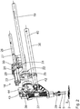
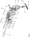
- the Fig. 2 to 7 show details of a needle transporting device 18 for generating the needle transport, in which the sewing needles 4, 5, which are to be transported into the sewing material, transport the sewing material in the sewing direction 2 or against the sewing direction 2, or where the sewing needles 4, 5 piercing the sewing material have no material transport function ,
- the Fig. 2 and 3 show the needle transport device 18 in a setting position "needle transport in the sewing direction 2", ie in the positive x direction.
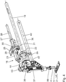
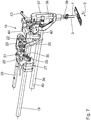
- the Fig. 4 and 5 show the setting position of the needle transport device 18 for needle transport against the sewing direction 2, ie in the negative x direction.
- the Fig. 6 and 7 show the needle conveyor 18 in the setting position at which the sewing needles 4, 5 have no fabric transport function.
- a needle transport drive is derived from an arm shaft 19, which in an arm 20 (see. Fig. 2 ) of the sewing machine 3 runs. At a free end, the arm shaft 19 is rotatably connected to a manually operable handwheel 21.
- the arm shaft 19 acts on a needle transport adjustment 23.
- the adjusting 23 is designed as a linkage.
- the arm shaft 19 is driven by a motor motor, which is not shown in the drawing and, for example, in a stand 24 or in the base frame 11 below the platen 7 of the sewing machine 3 can be accommodated.
- the adjusting mechanism 23 causes an oscillating drive of a driven lever 25 of the needle conveyor 18.
- a swing angle or a vibration amplitude of the output lever 25 is predetermined by a respective transmission setting of the adjusting 23.
- This gear adjustment is done by rotating a control shaft in the form of a transmission shaft 26 which cooperates with the adjusting gear 23 and also runs parallel to the arm shaft 19. Depending on the angular position of the gear shaft 26 results in another transport stroke of the needle transport in the sewing direction. 2
- An angular position of the transmission shaft 26 can be changed over by means of a needle transport changeover device 27, which is designed as a servomotor in the form of a stepper motor.
- the latter is firmly connected via a frame tab 28 in a manner not shown with a frame of the sewing machine 3.
- a motor shaft 29 of the stepping motor 27 is connected to the gear shaft 26 via a lever gear 30.
- a frame of the adjusting gear 23, a driven lever component 31 of the lever mechanism 30 and the gear shaft 26 are rotatably connected to each other.
- a pivoting movement of the motor shaft 29, starting from the neutral position in the Fig. 6 and 7 is +/- 30 ° to reach the two positions maximum "needle feed forward" after the Fig. 2 and 3 as well as maximum “needle transport backwards" after the Fig. 4 and 5 ,
- the stepper motor 27 is in signal communication with the central control device 9 of the sewing unit 1.
- this control device 9 for example, the material feed drive via the fabric clamp 8, the stepper motor of the needle transport changeover device 27 and the drive motor for the arm shaft 19 are actuated.
- the needle transport device 18 can be switched between the three in the Fig. 2 to 7 Positions shown "needle transport in sewing direction 2" (see. Fig. 2 / 3 ), “Needle transport opposite to the sewing direction 2" (cf. Fig. 4 / 5 ) and "Neutral position without needle transport function" (cf. Fig. 6 / 7 ).
- the output lever 25 transmits the oscillation amplitude predetermined via the adjusting mechanism 23 to a needle bar linkage shaft 36.
- An oscillation amplitude of the needle bar linkage shaft 36 is thus predetermined via the oscillation amplitude of the output lever 25.
- the Nadelstangenkulissen shaft 36 is parallel to the arm shaft 19th
- the Nadelstangenkulissen shaft 36 is rotatably connected to a Nadelstangenkulisse 37 for a needle bar 38, at the needle needles 39, the two sewing needles 4 and 5 are fixed.
- the needles 4, 5 oscillate about a needle transport pivot axis 40.
- a Armwellenkurbel 42 for up and down operation of the needle bar 38 and a thread lever 43 including a Fadenhebellenkers 44 with bearing.
- the respective seam is sewn with simultaneously driven feed of the sewing material in the sewing direction 2, that is to say in the sewing material feed direction, by means of the sewing material feed drive, ie by means of the sewing material clamp 8.
- the needle transport device 18 is operated in such a way that the needles 4, 5 transport the material to be sutured against the material feed direction 2 during the respective stitch. It is during the sewing so an operating position of the needle transport device 18 either according to the Fig. 4 and 5 or an intermediate position predetermined by the respective step position of the servomotor 27 between the position "maximum needle feed backwards" after the Fig. 4 and 5 and the neutral position after the Fig. 6 and 7 in front.
- About the stepping motor 27 can be a quasi stepless adjustment between the position "maximum needle transport forward / backward" after the Fig. 2 / 3 or 4/5 and the neutral position after the Fig. 6 / 7 cause.
- the fabric feed drive so the fabric clamp 8, operates, as far as this material feed drive during a sting has a periodic operation, during each stitch with an adjustable phase reference to the needle conveyor 18.
- this phase reference can be adjusted during the formation of the respective seam and even during the respective stitch.
- a needle feed stride length which can be predetermined via the servo motor 27, by which the material to be sutured during a stitch with the needle transport device 18, can be absolutely smaller than a feed stride length, by which the fabric is transported during sewing with the Nähgutklammer 8. In principle, it is also possible that the needle feed stride length is absolutely greater than the feed stride length.
- An absolute step length ratio needle transport step length / feed step length in the range between 1/10 and 2/1 is possible, in particular in the range between 1/10 and 8/10, in the range between 2/10 and 7/10 and for example in the range of 3/10, in the range of 4/10, in the range of 5/10 or even in the range of 6/10.
- a stride length of the fabric advancing step may be in the range of 2.5 mm.
- An absolute needle-feed stride length can be in the range between 0.1 mm to 3.5 mm in the opposite operation.
- the sewing material feed drive can also be designed as an upper feed and / or as an underfeed.
- a transporter for providing a Nähgut-top transport is known from the DE 196 03 294 C1
- a transporter for providing a Nähgut Untertransports is known from the EP 2 330 241 B1 ,
- the switching of the needle transport step length can be controlled, for example, depending on a detection of a fabric thickness.
- the control device 9 communicate with a material thickness sensor, not shown, and actuate the servomotor 27 upon reaching a predetermined Nähgutdicke.
- a changeover of the needle transport can also be effected as a function of a measured material transport speed. For this purpose, for example with the aid of an optical sensor, the speed of the material conveyance is monitored during the sewing process.
Landscapes
- Engineering & Computer Science (AREA)
- Textile Engineering (AREA)
- Sewing Machines And Sewing (AREA)
Abstract
Description
- Die vorliegende Patentanmeldung nimmt die Priorität der deutschen Patentanmeldung
DE 10 2017 216 725.4 in Anspruch, deren Inhalt durch Bezugnahme hierin aufgenommen wird. - Die Erfindung betrifft ein Verfahren zum Betrieb einer Nähmaschine. Ferner betrifft die Erfindung eine Nähmaschine zur Durchführung dieses Verfahrens.
- Ein Betriebsverfahren für eine Nähmaschine ist bekannt aus der
EP 3 088 589 A1 und aus derDE 100 22 237 B4 . DieDE 10 2011 100 103 A1 beschreibt eine Nähmaschine mit Nadeltransport zur Variation einer Stichlänge. DieDE-PS 1 485 148 DE 34 11 217 A1 beschreibt eine Doppelkettenstich-Nähmaschine mit unter Last über ein Schubgetriebe vorgebbaren Betrag eines Stoffvorschubes bzw. einer Nadelschwingbewegung. DieDE 10 2007 004 549 A1 beschreibt eine Vorschubeinstellvorrichtung einer Nähmaschine. DieDE-PS 868 832 DE 33 42 391 C1 beschreibt eine Nähmaschine mit Nadel- und Untertransport. - Es ist eine Aufgabe der vorliegenden Erfindung, eine Nähmaschine der eingangs genannten Art derart weiterzubilden, dass ein Nahtbild verbessert ist.
- Diese Aufgabe ist erfindungsgemäß gelöst durch ein Betriebsverfahren mit den im Anspruch 1 angegebenen Merkmalen.
- Überraschend hat sich herausgestellt, dass, abhängig von einer Nähgutbeschaffenheit und einer Nähgutdicke sowie abhängig von Nähfadenparametern es zu einer Verbesserung eines Nahtbildes führt, wenn eine Nadeltransporteinrichtung zum Vorschub des Nähguts in Gegenrichtung zur Nähgut-Vorschubrichtung eines zusätzlichen Nähgut-Vorschubantriebs betrieben wird. Obwohl bei einem derartigen "Gegeneinander-Betrieb" der Nadeltransporteinrichtung einerseits und dessen Nähgut-Vorschubantriebs andererseits eine Verschlechterung des Nahtbildes zu erwarten wäre, ergibt sich tatsächlich abhängig vom Nähgut und vom Nähfaden reproduzierbar aufgrund eines solchen Gegeneinander-Betriebs eine Nahtbildverbesserung.
- Ein einstellbarer Phasenbezug nach Anspruch 2 ermöglicht eine Feineinstellung des Gegeneinander-Betriebs zwischen einem periodischen Betriebsablauf des Nähgut-Vorschubantriebs und der Nadeltransporteinrichtung, was zur Optimierung des Nahtbildes genutzt werden kann. Eine Periode des jeweiligen Betriebsablaufs des Nähgut-Vorschubantriebs einerseits und der Nadeltransporteinrichtung andererseits kann mit der Periode der Bildung genau eines Stichs der Nähmaschine zusammen fallen.
- Die Vorteile einer Betriebsablauf-Feineinstellung gelten insbesondere für eine Phasenbezug-Verstellung nach Anspruch 3. Hierbei kann beispielsweise zu Beginn einer zu nähenden Naht ein erster Phasenbezug zwischen den periodischen Betriebsabläufen des Nähgut-Vorschubantriebs und der Nadeltransporteinrichtung und am Ende der Naht ein anderer derartiger Phasenbezug vorliegen. Mit dieser Phasenbezug-Verstellung kann wechselnden Nähbedingungen während der Nahtbildung Rechnung getragen werden.
- Ein Schrittlängenverhältnis nach Anspruch 4 hat sich für die Verbesserung eines Nahtbildes als besonders geeignet herausgestellt. Das absolute Verhältnis Nadeltransport-Schrittlänge/Vorschub-Schrittlänge kann im Bereich zwischen 1/10 und 2/1 liegen. Die Nadeltransport-Schrittlänge kann in Gegeneinander-Betrieb grundsätzlich also auch absolut größer sein als die Vorschub-Schrittlänge.
- Die Vorteile einer Nähmaschine zur Durchführung des erfindungsgemäßen Verfahrens entsprechen denen, die vorstehend unter Bezugnahme auf das Betriebsverfahren bereits erläutert wurden. Bei der Nähmaschine kann es sich um eine Ein-Nadel-Nähmaschine oder auch um eine Zwei-Nadel-Nähmaschine handeln.
- Eine Nähgutklammer als Nähgut-Vorschubantrieb ermöglicht eine unabhängige Ansteuerung des Nähgut-Vorschubs in der Nähgut-Vorschubeinrichtung relativ zur Ansteuerung der Nadeltransporteinrichtung. Alternativ kann der Nähgut-Vorschubantrieb auch als Obertransport mit mindestens einem Obertransporteur und/oder als Untertransport mit mindestens einem Untertransporteur ausgebildet sein. Der Nähgut-Vorschubantrieb kann das zu nähende Nähgut durch Reibschluss mit dem Nähgut während der Nahtbildung transportieren.
- Ein Schrittmotor nach Anspruch 7 ermöglicht eine präzise Vorgabe einer Nadeltransport-Schrittlänge, wobei diese mit enger Abstufung und insbesondere quasi stufenlos eingestellt werden kann.
- Eine Steuereinrichtung nach Anspruch 8 ermöglicht eine flexible Vorgabe des Gegeneinander-Betriebs zwischen dem Nähgut-Vorschubantrieb und der Nadeltransporteinrichtung.
- Ein Ausführungsbeispiel der Erfindung wird nachfolgend anhand der Zeichnung näher erläutert. In dieser zeigen:
- Fig. 1
- perspektivisch eine Gesamtansicht von Hauptkomponenten einer Nähanlage einschließlich einer Zweinadel-Nähmaschine;
- Fig. 2 und 3
- jeweils perspektivisch eine Nadeltransport-Baugruppe der Nähmaschine einschließlich der von einer Armwelle abgeleiteten Nadeltransport-Antriebs- und Einstellungskomponenten in einer Stellung "Vorwärts-Nadel-Transport";
- Fig. 4 und 5
- zu den
Fig. 2 und3 ähnliche Ansichten der Nadeltransport-Baugruppe in der Stellung "Rückwärts-Nadeltransport"; und - Fig. 6 und 7
- zu den
Fig. 4 und5 ähnliche Ansichten der Nadeltransport-Baugruppe in der Stellung "Neutral-Nadeltransport". -
Fig. 1 zeigt teils schematisch Hauptkomponenten einer Nähanlage 1 insbesondere zur Herstellung z.B. von paspelierten Taschen mit einer Taschenöffnung. Mit der Nähanlage 1 kann ein Zusatz-Nähgutteil, beispielsweise ein Paspelstreifen, mit einem Basis-Nähgutteil, beispielsweise einem Hosen- oder einem Sakkoteil, vernäht werden. Auch Patten- oder Leistentaschen können mit der Nähanlage genäht werden. - Beim Nähen von Nähten in das Nähgut wird dieses gleichzeitig angetrieben in eine Nähgut-Vorschubrichtung 2, die nachfolgend auch als Nährichtung bezeichnet ist, vorgeschoben. Die Nährichtung 2 verläuft längs einer x-Richtung eines in der
Fig. 1 eingezeichneten kartesischen xyz-Koordinatensystems. - Die Nähanlage 1 weist zum Nähen des Nähguts eine Nähmaschine 3 auf, die als Zweinadel-Nähmaschine mit Nähnadeln 4, 5 (vgl. z.B.
Fig. 2 ) ausgebildet ist. Den Nähnadeln 4, 5, gesehen in der Nährichtung 2 vorgeordnet, also in negativer x-Richtung versetzt, ist eine nicht näher dargestellte Paspel- beziehungsweise Patten-Falt- und -Zuführeinrichtung. Eine grundsätzliche Funktion dieser Paspel-Zuführeinrichtung ist aus dem Stand der Technik bekannt. Hierzu wird verwiesen auf die VorveröffentlichungenDE 100 16 410 C1 ,DE 199 26 866 C1 undDE 198 45 624 C1 sowie die dort angegebenen Referenzen. - Das Nähgut liegt auf einer Auflageplatte 7 der Nähanlage 1 auf. Die Auflageplatte 7 gibt eine Auflageebene vor, die parallel zur xy-Ebene verläuft.
- Zum Niederhalten von Nähgut jeweils auf einer Seite einer zu erzeugenden Naht gegen die Auflageplatte 7 sowie zum Nähguttransport längs der Nährichtung 2 dient eine angetriebene Nähgutklammer 8, die in der
Fig. 1 lediglich schematisch gestrichelt angedeutet ist und die grundsätzlich als Nähgut-Vorschubantrieb bekannt ist aus derEP 3 088 589 A . Die Nähmaschine 3 ermöglicht einen wahlweise, zum Beispiel phasenweise, zuschaltbaren Nadeltransport des Nähguts. - Zur Auswahl eines Nähprogramms, zur Eingabe von Nähdaten sowie zur Überwachung des Nähvorgangs dient ein betätigbares Display der Nähanlage 1, bei dem es sich um einen Touchscreen handeln kann. Das nicht dargestellte Display wird über eine schematisch in der
Fig. 1 dargestellte zentrale Steuereinrichtung 9 angesteuert. - Die Nähgutklammer 8 einschließlich eines Klammerrahmens ist abgedeckt von einer Abdeckhaube 10.
- Die Nähanlage 1 hat ein Grundgestell 11, das die Nähmaschine 3 sowie Nähgut-Zuführ-Transportkomponenten zum Zuführen von Nähgut zum Stichbildungsbereich und Nähgut-Abführkomponenten zum Abführen des Nähguts vom Stichbildungsbereich trägt. Das Grundgestell 11 umfasst die Auflageplatte 7. Ein Gleitblech 12 der Nähanlage 1 ist im Bereich der Auflageplatte 7 montiert. Auf dem Gleitblech 12 gleitet das Nähgut beim Transport.
- Die
Fig. 2 bis 7 zeigen Details einer Nadeltransporteinrichtung 18 zur Erzeugung des Nadeltransports, bei dem die in das Nähgut einstechenden Nähnadeln 4, 5 das Nähgut in der Nährichtung 2 oder entgegen der Nährichtung 2 transportieren oder bei den die in das Nähgut einstechenden Nähnadeln 4, 5 keine Nähgut-Transportfunktion haben. DieFig. 2 und3 zeigen dabei die Nadeltransporteinrichtung 18 in einer Einstellposition "Nadeltransport in der Nährichtung 2", also in positiver x-Richtung. DieFig. 4 und5 zeigen die Einstellposition der Nadeltransporteinrichtung 18 zum Nadeltransport entgegen der Nährichtung 2, also in negativer x-Richtung. DieFig. 6 und7 zeigen die Nadeltransporteinrichtung 18 in der Einstellposition, bei der die Nähnadeln 4, 5 keine Nähgut-Transportfunktion haben. - Ein Nadeltransportantrieb wird abgeleitet von einer Armwelle 19, die in einem Arm 20 (vgl.
Fig. 2 ) der Nähmaschine 3 verläuft. An einem freien Ende ist die Armwelle 19 drehfest mit einem manuell betätigbaren Handrad 21 verbunden. - Über einen Exzenter 22 wirkt die Armwelle 19 auf ein Nadeltransport-Verstellgetriebe 23. Das Verstellgetriebe 23 ist als Laschengetriebe ausgeführt.
- Im Nähbetrieb ist die Armwelle 19 motorisch von einem Antriebsmotor angetrieben, der in der Zeichnung nicht dargestellt ist und beispielsweise in einem Ständer 24 oder im Grundgestell 11 unterhalb der Auflageplatte 7 der Nähmaschine 3 untergebracht sein kann.
- Das Verstellgetriebe 23 bewirkt einen Schwingantrieb eines Abtriebshebels 25 der Nadeltransporteinrichtung 18. Ein Schwingwinkel beziehungsweise eine Schwingamplitude des Abtriebshebels 25 ist von einer jeweiligen Getriebeeinstellung des Verstellgetriebes 23 vorgegeben. Diese Getriebeeinstellung geschieht über ein Verdrehen einer Stellwelle in Form einer Getriebewelle 26, die mit dem Verstellgetriebe 23 zusammenwirkt und ebenfalls parallel zur Armwelle 19 verläuft. Je nach Winkelstellung der Getriebewelle 26 resultiert ein anderer Transporthub des Nadeltransports in der Nährichtung 2.
- Eine Winkelstellung der Getriebewelle 26 kann umgestellt werden mittels einer Nadeltransport-Umstelleinrichtung 27, die ausgeführt ist als Stellmotor in Form eines Schrittmotors. Letzterer ist über eine Rahmenlasche 28 in nicht näher dargestellter Weise mit einem Rahmen der Nähmaschine 3 festverbunden. Eine Motorwelle 29 des Schrittmotors 27 ist über ein Hebelgetriebe 30 mit der Getriebewelle 26 verbunden. Ein Rahmen des Verstellgetriebes 23, eine Abtriebs-Hebelkomponente 31 des Hebelgetriebes 30 und die Getriebewelle 26 sind drehfest miteinander verbunden. Eine Schwenkbewegung der Motorwelle 29 ausgehend von der Neutralstellung in den
Fig. 6 und7 beträgt +/- 30° zum Erreichen der beiden Stellungen maximaler "Nadeltransport vorwärts" nach denFig. 2 und3 sowie maximaler "Nadeltransport rückwärts" nach denFig. 4 und5 . - Der Schrittmotor 27 steht mit der zentralen Steuereinrichtung 9 der Nähanlage 1 in Signalverbindung. Über diese Steuereinrichtung 9 werden beispielsweise der Nähgut-Vorschubantrieb über die Nähgutklammer 8, der Schrittmotor der Nadeltransport-Umstelleinrichtung 27 sowie der Antriebsmotor für die Armwelle 19 angesteuert.
- Über die Nadeltransport-Umstelleinrichtung 27 kann die Nadeltransport-einrichtung 18 umgestellt werden zwischen den drei in den
Fig. 2 bis 7 dargestellten Positionen "Nadeltransport in Nährichtung 2" (vgl.Fig. 2 /3 ), "Nadeltransport entgegen der Nährichtung 2" (vgl.Fig. 4 /5 ) und "Neutralstellung ohne Nadeltransportfunktion" (vgl.Fig. 6 /7 ). - Der Abtriebshebel 25 überträgt die über das Verstellgetriebe 23 vorgegebene Schwingamplitude auf eine Nadelstangenkulissen-Welle 36. Eine Schwingamplitude der Nadelstangenkulissen-Welle 36 wird also über die Schwingamplitude des Abtriebshebels 25 vorgegeben. Auch die Nadelstangenkulissen-Welle 36 verläuft parallel zur Armwelle 19.
- Die Nadelstangenkulissen-Welle 36 ist drehfest mit einer Nadelstangenkulisse 37 für eine Nadelstange 38 verbunden, an der über einen Nadelkloben 39 die beiden Nähnadeln 4 und 5 festgelegt sind.
- Je nach der Schwingamplitude der Nadelstangenkulissen-Welle 36 schwingen die Nadeln 4, 5 um eine Nadeltransport-Schwingachse 40.
- Weiterhin dargestellt in den
Fig. 2 und7 sind eine Armwellenkurbel 42 zur auf- und abwärtsgerichteten Betätigung der Nadelstange 38 und ein Fadenhebel 43 einschließlich eines Fadenhebellenkers 44 mit Lagerstelle. - Beim Betrieb der Nähmaschine 3 wird die jeweilige Naht bei gleichzeitig angetriebenem Vorschub des Nähguts in der Nährichtung 2, also in der Nähgut-Vorschubrichtung, mittels des Nähgut-Vorschubantriebes, also mittels der Nähgutklammer 8, genäht. Während dieses Nähens der jeweiligen Naht wird die Nadeltransporteinrichtung 18 derart betrieben, dass die Nadeln 4, 5 das Nähgut während des jeweiligen Stichs entgegen der Nähgut-Vorschubrichtung 2 transportieren. Es liegt während des Nähvorgangs also eine Betriebsstellung der Nadeltransporteinrichtung 18 entweder gemäß den
Fig. 4 und5 oder eine über die jeweilige Schrittstellung des Stellmotors 27 vorgegebene Zwischenstellung zwischen der Stellung "Maximaler Nadeltransport rückwärts" nach denFig. 4 und5 und der Neutralstellung nach denFig. 6 und7 vor. - Über den Schrittmotor 27 lässt sich eine quasi stufenlose Verstellung zwischen der Stellung "Maximaler Nadeltransport vorwärts/rückwärts" nach den
Fig. 2 /3 bzw. 4/5 und der Neutralstellung nach denFig. 6 /7 herbeiführen. - Der Nähgut-Vorschubantrieb, also die Nähgutklammer 8, arbeitet, soweit dieser Nähgut-Vorschubantrieb während eines Stichs einen periodischen Betriebsablauf aufweist, während des jeweiligen Stichs mit einem einstellbaren Phasenbezug zur Nadeltransporteinrichtung 18. Durch entsprechende Ansteuerung des Vorschubantriebes der Nähgutklammer 8 über die Steuereinrichtung 9 kann dieser Phasenbezug während der Ausbildung der jeweiligen Naht und sogar während des jeweiligen Stichs verstellt werden.
- Eine über den Stellmotor 27 vorgebbare Nadeltransport-Schrittlänge, um die das Nähgut während eines Stichs mit der Nadeltransport-Einrichtung 18 transportiert wird, kann absolut kleiner sein als eine Vorschub-Schrittlänge, um die das Nähgut während des Stichs mit der Nähgutklammer 8 transportiert wird. Grundsätzlich ist auch möglich, dass die Nadeltransport-Schrittlänge absolut größer ist als die Vorschub-Schrittlänge. Ein absolutes Schrittlängenverhältnis Nadeltransport-Schrittlänge/Vorschub-Schrittlänge im Bereich zwischen 1/10 und 2/1 ist möglich, insbesondere im Bereich zwischen 1/10 und 8/10, im Bereich zwischen 2/10 und 7/10 und beispielsweise im Bereich von 3/10, im Bereich von 4/10, im Bereich von 5/10 oder auch im Bereich von 6/10. Eine Schrittlänge des Nähgut-Vorschubschritts kann im Bereich von 2,5 mm liegen. Eine absolute Nadel-transport-Schrittlänge kann im Gegeneinander-Betrieb im Bereich zwischen 0,1 mm bis 3,5 mm liegen.
- Alternativ zu einem als Nähgutklammer ausgeführten Nähgut-Vorschubantrieb kann der Nähgut-Vorschubantrieb auch als Obertransport und/oder als Untertransport ausgebildet sein. Ein Transporteur zur Bereitstellung eines Nähgut-Obertransports ist bekannt aus der
DE 196 03 294 C1 . Ein Transporteur zur Bereitstellung eines Nähgut-Untertransports ist bekannt aus derEP 2 330 241 B1 . - Das Umstellen der Nadeltransport-Schrittlänge kann gesteuert beispielsweise abhängig von einem Erfassen einer Nähgut-Dicke erfolgen. Hierzu kann die Steuereinrichtung 9 mit einem nicht dargestellten Nähgut-Dickensensor kommunizieren und beim Erreichen einer vorgegebenen Nähgutdicke den Stellmotor 27 betätigen. Ein Umstellen des Nadeltransports kann auch abhängig von einer gemessenen Nähgut-Transportgeschwindigkeit erfolgen. Hierzu wird, zum Beispiel mit Hilfe eines optischen Sensors, die Geschwindigkeit des Nähguttransports während des Nähvorgangs überwacht.
Claims (8)
- Verfahren zum Betrieb einer Nähmaschine (3) mit folgenden Schritten- Nähen mindestens einer Naht in Nähgut bei gleichzeitig angetriebenem Vorschub des Nähguts in einer Nähgut-Vorschubrichtung (2) mittels eines Nähgut-Vorschubantriebs (8),- Betreiben einer Nadeltransporteinrichtung (18) der Nähmaschine (3) während des Nähens der Naht derart, dass eine Nadel (4, 5) das Nähgut während eines jeweiligen Stichs entgegen der Nähgut-Vorschubrichtung (2) transportiert.
- Verfahrens nach Anspruch 1, dadurch gekennzeichnet, dass der Nähgut-Vorschubantrieb (8) mit einem einstellbaren Phasenbezug zur Nadeltransporteinrichtung (18) arbeitet.
- Verfahren nach Anspruch 2, dadurch gekennzeichnet, dass der Phasenbezug während des Nähens der Naht verstellt wird.
- Verfahren nach einem der Ansprüche 1 bis 3, dadurch gekennzeichnet, dass eine Nadeltransport-Schrittlänge, um die das Nähgut während eines Stichs mit der Nadeltransporteinrichtung (18) transportiert wird, absolut kleiner ist als eine Vorschub-Schrittlänge, um die das Nähgut während eines Stichs mit dem Nähgut-Vorschubantrieb (8) transportiert wird.
- Nähmaschine (3) zur Durchführung des Verfahrens nach einem der Ansprüche 1 bis 4.
- Nähmaschine nach Anspruch 5, dadurch gekennzeichnet, dass der Nähgut-Vorschubantrieb (8) als Nähgutklammer ausgeführt ist.
- Nähmaschine nach Anspruch 5 oder 6, dadurch gekennzeichnet, dass die Nadeltransporteinrichtung (18) einen Schrittmotor (27) aufweist, der auf eine Stellwelle (26) zum Umstellen einer Nadeltransport-Schrittlänge wirkt.
- Nähmaschine nach einem der Ansprüche 5 bis 7, gekennzeichnet durch eine Steuereinrichtung (9) zur Vorgabe eines Phasenbezuges zwischen dem Nähgut-Vorschubantrieb (8) und der Nadeltransporteinrichtung (18).
Applications Claiming Priority (1)
| Application Number | Priority Date | Filing Date | Title |
|---|---|---|---|
| DE102017216725.4A DE102017216725A1 (de) | 2017-09-21 | 2017-09-21 | Verfahren zum Betrieb einer Nähmaschine sowie Nähmaschine zur Durchführung des Verfahrens |
Publications (2)
| Publication Number | Publication Date |
|---|---|
| EP3460116A1 true EP3460116A1 (de) | 2019-03-27 |
| EP3460116B1 EP3460116B1 (de) | 2022-06-15 |
Family
ID=63528645
Family Applications (1)
| Application Number | Title | Priority Date | Filing Date |
|---|---|---|---|
| EP18193268.2A Active EP3460116B1 (de) | 2017-09-21 | 2018-09-07 | Verfahren zum betrieb einer nähmaschine sowie nähmaschine zur durchführung des verfahrens |
Country Status (6)
| Country | Link |
|---|---|
| EP (1) | EP3460116B1 (de) |
| JP (1) | JP2019055188A (de) |
| KR (1) | KR102554632B1 (de) |
| CN (1) | CN109537173B (de) |
| DE (1) | DE102017216725A1 (de) |
| TW (1) | TWI820040B (de) |
Families Citing this family (3)
| Publication number | Priority date | Publication date | Assignee | Title |
|---|---|---|---|---|
| JP7356260B2 (ja) * | 2019-05-17 | 2023-10-04 | Juki株式会社 | 針送りミシン |
| TWI764054B (zh) * | 2019-10-17 | 2022-05-11 | 陳儀聰 | 縫紉裝置 |
| IT202100000398A1 (it) * | 2021-01-12 | 2022-07-12 | Moncler S P A | Procedimento e apparecchiatura di produzione di articoli in tessuto o in pelle. |
Citations (3)
| Publication number | Priority date | Publication date | Assignee | Title |
|---|---|---|---|---|
| US3687096A (en) * | 1970-12-23 | 1972-08-29 | Union Special Machine Co | Feed adjusting mechanism for sewing machines |
| DE10022237A1 (de) * | 1999-05-07 | 2000-12-07 | Juki Kk | Nadelvorschub-Nähmaschine |
| DE10104218A1 (de) * | 2000-02-02 | 2001-08-09 | Brother Ind Ltd | Nähmaschine mit Nadel |
Family Cites Families (20)
| Publication number | Priority date | Publication date | Assignee | Title |
|---|---|---|---|---|
| DE868832C (de) * | 1941-01-29 | 1953-02-26 | Singer Mfg Co | Vorschubvorrichtung fuer Naehmaschinen |
| DE1485148B1 (de) * | 1964-01-22 | 1969-09-04 | Richard Flachmann | Naehmaschine mit Nadelvorschub,insbesondere AErmeleinnaehmaschine |
| DE3342391C1 (de) * | 1983-11-24 | 1985-03-14 | Pfaff Industriemaschinen Gmbh, 6750 Kaiserslautern | Naehmaschine mit Nadel und Untertransport und einer Einrichtung zum Ansteuern eines vorbestimmten Endpunktes einer Naht |
| DE3411217C2 (de) * | 1984-03-27 | 1989-11-02 | Kochs Adler Ag, 4800 Bielefeld | Doppelkettenstich-Nähmaschine |
| DE19603294C1 (de) | 1996-01-30 | 1997-09-25 | Duerkopp Adler Ag | Nähmaschine mit Obertransportvorrichtung |
| JP3714578B2 (ja) * | 1997-10-02 | 2005-11-09 | Juki株式会社 | 針送りミシン |
| DE19845624C1 (de) | 1998-10-05 | 2000-05-11 | Duerkopp Adler Ag | Nähanlage zur Herstellung einer paspelierten Taschenöffnung |
| DE19903264C1 (de) * | 1999-01-28 | 2000-05-18 | Duerkopp Adler Ag | Gelenkgetriebe zur Erzeugung einer veränderbaren Schwingbewegung, insbesondere für den Antrieb des Stoffschiebers einer Nähmaschine |
| JP2001025591A (ja) * | 1999-05-07 | 2001-01-30 | Juki Corp | 針送りミシン |
| DE19926866C1 (de) | 1999-06-12 | 2000-08-24 | Duerkopp Adler Ag | Nähmaschine |
| JP4272766B2 (ja) * | 1999-09-06 | 2009-06-03 | Juki株式会社 | ミシンの送り装置 |
| DE10016410C1 (de) | 2000-04-01 | 2001-06-07 | Duerkopp Adler Ag | Patten-Zuführeinrichtung für eine Paspelstreifen-Nähanlage |
| JP4809551B2 (ja) * | 2001-07-19 | 2011-11-09 | Juki株式会社 | 針送りミシン |
| JP4823700B2 (ja) * | 2006-01-31 | 2011-11-24 | Juki株式会社 | ミシン |
| DE102007026651A1 (de) * | 2007-06-08 | 2008-12-18 | Dürkopp Adler AG | Nähmaschine sowie Betriebsverfahren für eine derartige Nähmaschine |
| DE102009047534A1 (de) | 2009-12-04 | 2011-06-09 | Dürkopp Adler AG | Nähmaschine |
| DE102011100103B4 (de) * | 2011-04-30 | 2025-01-02 | Pfaff Industriesysteme Und Maschinen Gmbh | Nähmaschine mit Nadeltransport |
| WO2015131069A1 (en) * | 2014-02-28 | 2015-09-03 | Card-Monroe Corp. | Variable stroke drive system for tufting machine |
| DE102015207758A1 (de) | 2015-04-28 | 2016-11-03 | Dürkopp Adler AG | Nähanlage sowie Betriebsverfahren hierfür |
| CN107761258B (zh) * | 2017-12-05 | 2024-02-06 | 浙江中捷缝纫科技有限公司 | 一种缝纫机的送布调节机构 |
-
2017
- 2017-09-21 DE DE102017216725.4A patent/DE102017216725A1/de not_active Ceased
-
2018
- 2018-09-07 EP EP18193268.2A patent/EP3460116B1/de active Active
- 2018-09-18 KR KR1020180111527A patent/KR102554632B1/ko active Active
- 2018-09-19 JP JP2018174673A patent/JP2019055188A/ja active Pending
- 2018-09-20 TW TW107133169A patent/TWI820040B/zh active
- 2018-09-20 CN CN201811101463.1A patent/CN109537173B/zh active Active
Patent Citations (3)
| Publication number | Priority date | Publication date | Assignee | Title |
|---|---|---|---|---|
| US3687096A (en) * | 1970-12-23 | 1972-08-29 | Union Special Machine Co | Feed adjusting mechanism for sewing machines |
| DE10022237A1 (de) * | 1999-05-07 | 2000-12-07 | Juki Kk | Nadelvorschub-Nähmaschine |
| DE10104218A1 (de) * | 2000-02-02 | 2001-08-09 | Brother Ind Ltd | Nähmaschine mit Nadel |
Also Published As
| Publication number | Publication date |
|---|---|
| TW201920796A (zh) | 2019-06-01 |
| JP2019055188A (ja) | 2019-04-11 |
| TWI820040B (zh) | 2023-11-01 |
| EP3460116B1 (de) | 2022-06-15 |
| DE102017216725A1 (de) | 2019-03-21 |
| CN109537173A (zh) | 2019-03-29 |
| KR102554632B1 (ko) | 2023-07-11 |
| KR20190033446A (ko) | 2019-03-29 |
| CN109537173B (zh) | 2022-06-14 |
Similar Documents
| Publication | Publication Date | Title |
|---|---|---|
| DE102017107281B4 (de) | Nähmaschine | |
| DE3216993A1 (de) | Naehmaschine mit einer einrichtung zum herstellen von formnaehten | |
| DE102007001073A1 (de) | Nähgutvorschubvorrichtung einer Nähmaschine | |
| EP3460116B1 (de) | Verfahren zum betrieb einer nähmaschine sowie nähmaschine zur durchführung des verfahrens | |
| DE102012207257B4 (de) | Nähmaschine | |
| DE102008010354B4 (de) | Einfassmaschine | |
| EP3088589B1 (de) | Nähanlage sowie betriebsverfahren hierfür | |
| DE3000831C2 (de) | Nähautomat zur Erzeugung einer eine Befestigungsnaht und Verriegelungsstiche aufweisenden Naht | |
| DE102007020139B4 (de) | Einfassmaschine | |
| DE102011118083A1 (de) | Nähmaschine mit einem Niederhalter für das Nähgut | |
| DE202015102109U1 (de) | Nähanlage | |
| DE102008053780B4 (de) | Einfassmaschine | |
| DE10125068C2 (de) | Nähmaschine mit einer Einrichtung zum Ansteuern eines Nahtendpunktes | |
| EP2182102B1 (de) | Nähmaschine | |
| DE3313981A1 (de) | Greiferbetaetigungsvorrichtung fuer naehmaschinen | |
| DE102008010353B4 (de) | Einfassmaschine | |
| DE69120238T2 (de) | Industrie-Nähmaschine, die gleichzeitig verschiedene Nähte ausführen kann | |
| DE3033023C2 (de) | ||
| EP3399089B1 (de) | Verfahren und nähmaschine zum erzeugen eines naht-endunterfadens mit vorgegebenem soll-nahtüberstand | |
| EP2360305B1 (de) | Verfahren zum Betrieb einer Nähmaschine und Nähmaschine | |
| DE3130372C2 (de) | Stickmaschine | |
| DE302832C (de) | ||
| DE199419C (de) | ||
| DE667147C (de) | Maschine zum Annaehen von Knoepfen mit einer oder mehreren Lochreihen | |
| WO1998031859A1 (de) | Blindstichnähmaschine |
Legal Events
| Date | Code | Title | Description |
|---|---|---|---|
| PUAI | Public reference made under article 153(3) epc to a published international application that has entered the european phase |
Free format text: ORIGINAL CODE: 0009012 |
|
| STAA | Information on the status of an ep patent application or granted ep patent |
Free format text: STATUS: THE APPLICATION HAS BEEN PUBLISHED |
|
| AK | Designated contracting states |
Kind code of ref document: A1 Designated state(s): AL AT BE BG CH CY CZ DE DK EE ES FI FR GB GR HR HU IE IS IT LI LT LU LV MC MK MT NL NO PL PT RO RS SE SI SK SM TR |
|
| AX | Request for extension of the european patent |
Extension state: BA ME |
|
| STAA | Information on the status of an ep patent application or granted ep patent |
Free format text: STATUS: REQUEST FOR EXAMINATION WAS MADE |
|
| 17P | Request for examination filed |
Effective date: 20190820 |
|
| RBV | Designated contracting states (corrected) |
Designated state(s): AL AT BE BG CH CY CZ DE DK EE ES FI FR GB GR HR HU IE IS IT LI LT LU LV MC MK MT NL NO PL PT RO RS SE SI SK SM TR |
|
| GRAP | Despatch of communication of intention to grant a patent |
Free format text: ORIGINAL CODE: EPIDOSNIGR1 |
|
| STAA | Information on the status of an ep patent application or granted ep patent |
Free format text: STATUS: GRANT OF PATENT IS INTENDED |
|
| RIC1 | Information provided on ipc code assigned before grant |
Ipc: D05B 27/20 20060101ALI20211213BHEP Ipc: D05B 27/00 20060101AFI20211213BHEP |
|
| INTG | Intention to grant announced |
Effective date: 20220119 |
|
| GRAS | Grant fee paid |
Free format text: ORIGINAL CODE: EPIDOSNIGR3 |
|
| GRAA | (expected) grant |
Free format text: ORIGINAL CODE: 0009210 |
|
| STAA | Information on the status of an ep patent application or granted ep patent |
Free format text: STATUS: THE PATENT HAS BEEN GRANTED |
|
| AK | Designated contracting states |
Kind code of ref document: B1 Designated state(s): AL AT BE BG CH CY CZ DE DK EE ES FI FR GB GR HR HU IE IS IT LI LT LU LV MC MK MT NL NO PL PT RO RS SE SI SK SM TR |
|
| REG | Reference to a national code |
Ref country code: CH Ref legal event code: EP Ref country code: GB Ref legal event code: FG4D Free format text: NOT ENGLISH |
|
| REG | Reference to a national code |
Ref country code: RO Ref legal event code: EPE |
|
| REG | Reference to a national code |
Ref country code: IE Ref legal event code: FG4D Free format text: LANGUAGE OF EP DOCUMENT: GERMAN |
|
| REG | Reference to a national code |
Ref country code: DE Ref legal event code: R096 Ref document number: 502018009906 Country of ref document: DE |
|
| REG | Reference to a national code |
Ref country code: AT Ref legal event code: REF Ref document number: 1498473 Country of ref document: AT Kind code of ref document: T Effective date: 20220715 |
|
| REG | Reference to a national code |
Ref country code: LT Ref legal event code: MG9D |
|
| REG | Reference to a national code |
Ref country code: NL Ref legal event code: MP Effective date: 20220615 |
|
| PG25 | Lapsed in a contracting state [announced via postgrant information from national office to epo] |
Ref country code: SE Free format text: LAPSE BECAUSE OF FAILURE TO SUBMIT A TRANSLATION OF THE DESCRIPTION OR TO PAY THE FEE WITHIN THE PRESCRIBED TIME-LIMIT Effective date: 20220615 Ref country code: NO Free format text: LAPSE BECAUSE OF FAILURE TO SUBMIT A TRANSLATION OF THE DESCRIPTION OR TO PAY THE FEE WITHIN THE PRESCRIBED TIME-LIMIT Effective date: 20220915 Ref country code: LT Free format text: LAPSE BECAUSE OF FAILURE TO SUBMIT A TRANSLATION OF THE DESCRIPTION OR TO PAY THE FEE WITHIN THE PRESCRIBED TIME-LIMIT Effective date: 20220615 Ref country code: HR Free format text: LAPSE BECAUSE OF FAILURE TO SUBMIT A TRANSLATION OF THE DESCRIPTION OR TO PAY THE FEE WITHIN THE PRESCRIBED TIME-LIMIT Effective date: 20220615 Ref country code: GR Free format text: LAPSE BECAUSE OF FAILURE TO SUBMIT A TRANSLATION OF THE DESCRIPTION OR TO PAY THE FEE WITHIN THE PRESCRIBED TIME-LIMIT Effective date: 20220916 Ref country code: FI Free format text: LAPSE BECAUSE OF FAILURE TO SUBMIT A TRANSLATION OF THE DESCRIPTION OR TO PAY THE FEE WITHIN THE PRESCRIBED TIME-LIMIT Effective date: 20220615 Ref country code: BG Free format text: LAPSE BECAUSE OF FAILURE TO SUBMIT A TRANSLATION OF THE DESCRIPTION OR TO PAY THE FEE WITHIN THE PRESCRIBED TIME-LIMIT Effective date: 20220915 |
|
| PG25 | Lapsed in a contracting state [announced via postgrant information from national office to epo] |
Ref country code: RS Free format text: LAPSE BECAUSE OF FAILURE TO SUBMIT A TRANSLATION OF THE DESCRIPTION OR TO PAY THE FEE WITHIN THE PRESCRIBED TIME-LIMIT Effective date: 20220615 Ref country code: LV Free format text: LAPSE BECAUSE OF FAILURE TO SUBMIT A TRANSLATION OF THE DESCRIPTION OR TO PAY THE FEE WITHIN THE PRESCRIBED TIME-LIMIT Effective date: 20220615 |
|
| PG25 | Lapsed in a contracting state [announced via postgrant information from national office to epo] |
Ref country code: NL Free format text: LAPSE BECAUSE OF FAILURE TO SUBMIT A TRANSLATION OF THE DESCRIPTION OR TO PAY THE FEE WITHIN THE PRESCRIBED TIME-LIMIT Effective date: 20220615 |
|
| PG25 | Lapsed in a contracting state [announced via postgrant information from national office to epo] |
Ref country code: SM Free format text: LAPSE BECAUSE OF FAILURE TO SUBMIT A TRANSLATION OF THE DESCRIPTION OR TO PAY THE FEE WITHIN THE PRESCRIBED TIME-LIMIT Effective date: 20220615 Ref country code: SK Free format text: LAPSE BECAUSE OF FAILURE TO SUBMIT A TRANSLATION OF THE DESCRIPTION OR TO PAY THE FEE WITHIN THE PRESCRIBED TIME-LIMIT Effective date: 20220615 Ref country code: PT Free format text: LAPSE BECAUSE OF FAILURE TO SUBMIT A TRANSLATION OF THE DESCRIPTION OR TO PAY THE FEE WITHIN THE PRESCRIBED TIME-LIMIT Effective date: 20221017 Ref country code: ES Free format text: LAPSE BECAUSE OF FAILURE TO SUBMIT A TRANSLATION OF THE DESCRIPTION OR TO PAY THE FEE WITHIN THE PRESCRIBED TIME-LIMIT Effective date: 20220615 Ref country code: EE Free format text: LAPSE BECAUSE OF FAILURE TO SUBMIT A TRANSLATION OF THE DESCRIPTION OR TO PAY THE FEE WITHIN THE PRESCRIBED TIME-LIMIT Effective date: 20220615 |
|
| PG25 | Lapsed in a contracting state [announced via postgrant information from national office to epo] |
Ref country code: PL Free format text: LAPSE BECAUSE OF FAILURE TO SUBMIT A TRANSLATION OF THE DESCRIPTION OR TO PAY THE FEE WITHIN THE PRESCRIBED TIME-LIMIT Effective date: 20220615 Ref country code: IS Free format text: LAPSE BECAUSE OF FAILURE TO SUBMIT A TRANSLATION OF THE DESCRIPTION OR TO PAY THE FEE WITHIN THE PRESCRIBED TIME-LIMIT Effective date: 20221015 |
|
| REG | Reference to a national code |
Ref country code: DE Ref legal event code: R097 Ref document number: 502018009906 Country of ref document: DE |
|
| PG25 | Lapsed in a contracting state [announced via postgrant information from national office to epo] |
Ref country code: AL Free format text: LAPSE BECAUSE OF FAILURE TO SUBMIT A TRANSLATION OF THE DESCRIPTION OR TO PAY THE FEE WITHIN THE PRESCRIBED TIME-LIMIT Effective date: 20220615 |
|
| PLBE | No opposition filed within time limit |
Free format text: ORIGINAL CODE: 0009261 |
|
| STAA | Information on the status of an ep patent application or granted ep patent |
Free format text: STATUS: NO OPPOSITION FILED WITHIN TIME LIMIT |
|
| PG25 | Lapsed in a contracting state [announced via postgrant information from national office to epo] |
Ref country code: MC Free format text: LAPSE BECAUSE OF FAILURE TO SUBMIT A TRANSLATION OF THE DESCRIPTION OR TO PAY THE FEE WITHIN THE PRESCRIBED TIME-LIMIT Effective date: 20220615 Ref country code: DK Free format text: LAPSE BECAUSE OF FAILURE TO SUBMIT A TRANSLATION OF THE DESCRIPTION OR TO PAY THE FEE WITHIN THE PRESCRIBED TIME-LIMIT Effective date: 20220615 |
|
| REG | Reference to a national code |
Ref country code: CH Ref legal event code: PL |
|
| 26N | No opposition filed |
Effective date: 20230316 |
|
| GBPC | Gb: european patent ceased through non-payment of renewal fee |
Effective date: 20220915 |
|
| REG | Reference to a national code |
Ref country code: BE Ref legal event code: MM Effective date: 20220930 |
|
| PG25 | Lapsed in a contracting state [announced via postgrant information from national office to epo] |
Ref country code: SI Free format text: LAPSE BECAUSE OF FAILURE TO SUBMIT A TRANSLATION OF THE DESCRIPTION OR TO PAY THE FEE WITHIN THE PRESCRIBED TIME-LIMIT Effective date: 20220615 |
|
| P01 | Opt-out of the competence of the unified patent court (upc) registered |
Effective date: 20230512 |
|
| PG25 | Lapsed in a contracting state [announced via postgrant information from national office to epo] |
Ref country code: LU Free format text: LAPSE BECAUSE OF NON-PAYMENT OF DUE FEES Effective date: 20220907 |
|
| PG25 | Lapsed in a contracting state [announced via postgrant information from national office to epo] |
Ref country code: LI Free format text: LAPSE BECAUSE OF NON-PAYMENT OF DUE FEES Effective date: 20220930 Ref country code: IE Free format text: LAPSE BECAUSE OF NON-PAYMENT OF DUE FEES Effective date: 20220907 Ref country code: FR Free format text: LAPSE BECAUSE OF NON-PAYMENT OF DUE FEES Effective date: 20220930 Ref country code: CH Free format text: LAPSE BECAUSE OF NON-PAYMENT OF DUE FEES Effective date: 20220930 |
|
| PG25 | Lapsed in a contracting state [announced via postgrant information from national office to epo] |
Ref country code: BE Free format text: LAPSE BECAUSE OF NON-PAYMENT OF DUE FEES Effective date: 20220930 |
|
| PG25 | Lapsed in a contracting state [announced via postgrant information from national office to epo] |
Ref country code: GB Free format text: LAPSE BECAUSE OF NON-PAYMENT OF DUE FEES Effective date: 20220915 |
|
| PG25 | Lapsed in a contracting state [announced via postgrant information from national office to epo] |
Ref country code: IT Free format text: LAPSE BECAUSE OF FAILURE TO SUBMIT A TRANSLATION OF THE DESCRIPTION OR TO PAY THE FEE WITHIN THE PRESCRIBED TIME-LIMIT Effective date: 20220615 |
|
| PG25 | Lapsed in a contracting state [announced via postgrant information from national office to epo] |
Ref country code: HU Free format text: LAPSE BECAUSE OF FAILURE TO SUBMIT A TRANSLATION OF THE DESCRIPTION OR TO PAY THE FEE WITHIN THE PRESCRIBED TIME-LIMIT; INVALID AB INITIO Effective date: 20180907 |
|
| PG25 | Lapsed in a contracting state [announced via postgrant information from national office to epo] |
Ref country code: CY Free format text: LAPSE BECAUSE OF FAILURE TO SUBMIT A TRANSLATION OF THE DESCRIPTION OR TO PAY THE FEE WITHIN THE PRESCRIBED TIME-LIMIT Effective date: 20220615 |
|
| PG25 | Lapsed in a contracting state [announced via postgrant information from national office to epo] |
Ref country code: MK Free format text: LAPSE BECAUSE OF FAILURE TO SUBMIT A TRANSLATION OF THE DESCRIPTION OR TO PAY THE FEE WITHIN THE PRESCRIBED TIME-LIMIT Effective date: 20220615 |
|
| PG25 | Lapsed in a contracting state [announced via postgrant information from national office to epo] |
Ref country code: MT Free format text: LAPSE BECAUSE OF FAILURE TO SUBMIT A TRANSLATION OF THE DESCRIPTION OR TO PAY THE FEE WITHIN THE PRESCRIBED TIME-LIMIT Effective date: 20220615 |
|
| PG25 | Lapsed in a contracting state [announced via postgrant information from national office to epo] |
Ref country code: BG Free format text: LAPSE BECAUSE OF FAILURE TO SUBMIT A TRANSLATION OF THE DESCRIPTION OR TO PAY THE FEE WITHIN THE PRESCRIBED TIME-LIMIT Effective date: 20220615 |
|
| REG | Reference to a national code |
Ref country code: AT Ref legal event code: MM01 Ref document number: 1498473 Country of ref document: AT Kind code of ref document: T Effective date: 20230907 |
|
| PG25 | Lapsed in a contracting state [announced via postgrant information from national office to epo] |
Ref country code: BG Free format text: LAPSE BECAUSE OF FAILURE TO SUBMIT A TRANSLATION OF THE DESCRIPTION OR TO PAY THE FEE WITHIN THE PRESCRIBED TIME-LIMIT Effective date: 20220615 |
|
| PG25 | Lapsed in a contracting state [announced via postgrant information from national office to epo] |
Ref country code: AT Free format text: LAPSE BECAUSE OF NON-PAYMENT OF DUE FEES Effective date: 20230907 |
|
| PG25 | Lapsed in a contracting state [announced via postgrant information from national office to epo] |
Ref country code: AT Free format text: LAPSE BECAUSE OF NON-PAYMENT OF DUE FEES Effective date: 20230907 |
|
| PGFP | Annual fee paid to national office [announced via postgrant information from national office to epo] |
Ref country code: CZ Payment date: 20250827 Year of fee payment: 8 |
|
| PGFP | Annual fee paid to national office [announced via postgrant information from national office to epo] |
Ref country code: RO Payment date: 20250901 Year of fee payment: 8 |
|
| PG25 | Lapsed in a contracting state [announced via postgrant information from national office to epo] |
Ref country code: TR Free format text: LAPSE BECAUSE OF FAILURE TO SUBMIT A TRANSLATION OF THE DESCRIPTION OR TO PAY THE FEE WITHIN THE PRESCRIBED TIME-LIMIT Effective date: 20220615 |
|
| PGFP | Annual fee paid to national office [announced via postgrant information from national office to epo] |
Ref country code: DE Payment date: 20251121 Year of fee payment: 8 |
|
| PGFP | Annual fee paid to national office [announced via postgrant information from national office to epo] |
Ref country code: AT Payment date: 20260410 Year of fee payment: 5 |