EP3460132A1 - Urinal mit siphonweganschlusssystem - Google Patents
Urinal mit siphonweganschlusssystem Download PDFInfo
- Publication number
- EP3460132A1 EP3460132A1 EP18193505.7A EP18193505A EP3460132A1 EP 3460132 A1 EP3460132 A1 EP 3460132A1 EP 18193505 A EP18193505 A EP 18193505A EP 3460132 A1 EP3460132 A1 EP 3460132A1
- Authority
- EP
- European Patent Office
- Prior art keywords
- assembly
- trapway
- bowl
- urinal
- wall
- Prior art date
- Legal status (The legal status is an assumption and is not a legal conclusion. Google has not performed a legal analysis and makes no representation as to the accuracy of the status listed.)
- Withdrawn
Links
- 230000008878 coupling Effects 0.000 claims description 26
- 238000010168 coupling process Methods 0.000 claims description 26
- 238000005859 coupling reaction Methods 0.000 claims description 26
- 239000012530 fluid Substances 0.000 claims description 3
- 239000007788 liquid Substances 0.000 description 24
- 230000003993 interaction Effects 0.000 description 7
- 239000000463 material Substances 0.000 description 7
- 238000012986 modification Methods 0.000 description 6
- 230000004048 modification Effects 0.000 description 6
- 210000002700 urine Anatomy 0.000 description 6
- 238000013461 design Methods 0.000 description 5
- 238000000034 method Methods 0.000 description 5
- -1 urine Substances 0.000 description 5
- 238000000576 coating method Methods 0.000 description 4
- 239000000203 mixture Substances 0.000 description 4
- 229910052782 aluminium Inorganic materials 0.000 description 3
- XAGFODPZIPBFFR-UHFFFAOYSA-N aluminium Chemical compound [Al] XAGFODPZIPBFFR-UHFFFAOYSA-N 0.000 description 3
- 230000005540 biological transmission Effects 0.000 description 3
- 239000000919 ceramic Substances 0.000 description 3
- 238000005304 joining Methods 0.000 description 3
- 230000008569 process Effects 0.000 description 3
- 238000006467 substitution reaction Methods 0.000 description 3
- 238000011282 treatment Methods 0.000 description 3
- 229910001369 Brass Inorganic materials 0.000 description 2
- 230000008901 benefit Effects 0.000 description 2
- 239000010951 brass Substances 0.000 description 2
- 238000004140 cleaning Methods 0.000 description 2
- 239000011248 coating agent Substances 0.000 description 2
- 239000010800 human waste Substances 0.000 description 2
- 238000012423 maintenance Methods 0.000 description 2
- 229920000642 polymer Polymers 0.000 description 2
- 229920005989 resin Polymers 0.000 description 2
- 239000011347 resin Substances 0.000 description 2
- 238000012552 review Methods 0.000 description 2
- 238000003860 storage Methods 0.000 description 2
- XLYOFNOQVPJJNP-UHFFFAOYSA-N water Substances O XLYOFNOQVPJJNP-UHFFFAOYSA-N 0.000 description 2
- 239000004677 Nylon Substances 0.000 description 1
- 229910000831 Steel Inorganic materials 0.000 description 1
- HCHKCACWOHOZIP-UHFFFAOYSA-N Zinc Chemical compound [Zn] HCHKCACWOHOZIP-UHFFFAOYSA-N 0.000 description 1
- 239000000853 adhesive Substances 0.000 description 1
- 230000001070 adhesive effect Effects 0.000 description 1
- 239000000956 alloy Substances 0.000 description 1
- 229910045601 alloy Inorganic materials 0.000 description 1
- 230000004075 alteration Effects 0.000 description 1
- PNEYBMLMFCGWSK-UHFFFAOYSA-N aluminium oxide Inorganic materials [O-2].[O-2].[O-2].[Al+3].[Al+3] PNEYBMLMFCGWSK-UHFFFAOYSA-N 0.000 description 1
- 238000007743 anodising Methods 0.000 description 1
- 230000000845 anti-microbial effect Effects 0.000 description 1
- 239000004599 antimicrobial Substances 0.000 description 1
- 230000000712 assembly Effects 0.000 description 1
- 238000000429 assembly Methods 0.000 description 1
- 238000005266 casting Methods 0.000 description 1
- 239000003086 colorant Substances 0.000 description 1
- 238000010276 construction Methods 0.000 description 1
- 210000003298 dental enamel Anatomy 0.000 description 1
- 238000009826 distribution Methods 0.000 description 1
- 229920001971 elastomer Polymers 0.000 description 1
- 230000005611 electricity Effects 0.000 description 1
- 239000003292 glue Substances 0.000 description 1
- 230000002209 hydrophobic effect Effects 0.000 description 1
- 238000005286 illumination Methods 0.000 description 1
- 238000001746 injection moulding Methods 0.000 description 1
- 238000009434 installation Methods 0.000 description 1
- 229910052751 metal Inorganic materials 0.000 description 1
- 239000002184 metal Substances 0.000 description 1
- 150000002739 metals Chemical class 0.000 description 1
- 238000000465 moulding Methods 0.000 description 1
- 229920001778 nylon Polymers 0.000 description 1
- 239000003973 paint Substances 0.000 description 1
- 239000004033 plastic Substances 0.000 description 1
- 229920003023 plastic Polymers 0.000 description 1
- 229920001343 polytetrafluoroethylene Polymers 0.000 description 1
- 239000004810 polytetrafluoroethylene Substances 0.000 description 1
- 229920000915 polyvinyl chloride Polymers 0.000 description 1
- 239000004800 polyvinyl chloride Substances 0.000 description 1
- 229910052573 porcelain Inorganic materials 0.000 description 1
- 239000000843 powder Substances 0.000 description 1
- 230000004044 response Effects 0.000 description 1
- 238000009420 retrofitting Methods 0.000 description 1
- 239000005060 rubber Substances 0.000 description 1
- 239000010959 steel Substances 0.000 description 1
- 238000004381 surface treatment Methods 0.000 description 1
- 229920003051 synthetic elastomer Polymers 0.000 description 1
- 239000005061 synthetic rubber Substances 0.000 description 1
- 229920001169 thermoplastic Polymers 0.000 description 1
- 229920001187 thermosetting polymer Polymers 0.000 description 1
- 239000004416 thermosoftening plastic Substances 0.000 description 1
- 238000012546 transfer Methods 0.000 description 1
- 229910052725 zinc Inorganic materials 0.000 description 1
- 239000011701 zinc Substances 0.000 description 1
Images


Classifications
-
- E—FIXED CONSTRUCTIONS
- E03—WATER SUPPLY; SEWERAGE
- E03D—WATER-CLOSETS OR URINALS WITH FLUSHING DEVICES; FLUSHING VALVES THEREFOR
- E03D13/00—Urinals ; Means for connecting the urinal to the flushing pipe and the wastepipe; Splashing shields for urinals
-
- E—FIXED CONSTRUCTIONS
- E03—WATER SUPPLY; SEWERAGE
- E03D—WATER-CLOSETS OR URINALS WITH FLUSHING DEVICES; FLUSHING VALVES THEREFOR
- E03D13/00—Urinals ; Means for connecting the urinal to the flushing pipe and the wastepipe; Splashing shields for urinals
- E03D13/005—Accessories specially adapted for urinals
-
- E—FIXED CONSTRUCTIONS
- E03—WATER SUPPLY; SEWERAGE
- E03D—WATER-CLOSETS OR URINALS WITH FLUSHING DEVICES; FLUSHING VALVES THEREFOR
- E03D13/00—Urinals ; Means for connecting the urinal to the flushing pipe and the wastepipe; Splashing shields for urinals
- E03D13/007—Waterless or low-flush urinals; Accessories therefor
-
- E—FIXED CONSTRUCTIONS
- E03—WATER SUPPLY; SEWERAGE
- E03D—WATER-CLOSETS OR URINALS WITH FLUSHING DEVICES; FLUSHING VALVES THEREFOR
- E03D11/00—Other component parts of water-closets, e.g. noise-reducing means in the flushing system, flushing pipes mounted in the bowl, seals for the bowl outlet, devices preventing overflow of the bowl contents; devices forming a water seal in the bowl after flushing, devices eliminating obstructions in the bowl outlet or preventing backflow of water and excrements from the waterpipe
- E03D11/18—Siphons
Definitions
- the present Application relates generally to urinals.
- the present Application relates to a trapway connection system for a urinal.
- Urinals are secured to a wall through a fastener connection that is accessible via recesses in the side of the urinal. These recesses are often difficult to clean and may serve as hand holds for vandalism.
- Urinals typically utilize a trapway to transfer liquid (e.g., urine, etc.) from inside the urinal to a drain. Traditionally, this trapway is integrated within the urinal. As a result, contents of the trapway (e.g., urine, etc.) may be susceptible to spilling when the urinal is uninstalled or removed from the wall (e.g., for servicing, etc.).
- the urinal includes a bowl assembly and a trapway assembly.
- the bowl assembly includes a body.
- the body defines a bowl and a cavity.
- the cavity includes a receiver configured to receive a bracket.
- the trapway assembly is configured to be located in the cavity.
- the trapway assembly is configured to fluidly couple the bowl to a drain.
- the trapway assembly is configured to be coupled to the drain separate from the bowl assembly.
- the bowl assembly is configured to be coupled to a wall separate from the trapway assembly.
- the urinal includes a bowl assembly and a trapway assembly.
- the bowl assembly includes a body.
- the body defines a bowl and a cavity.
- the bowl assembly is configured to be coupled to a wall.
- the trapway assembly is configured to be located in the cavity.
- the trapway assembly is configured to fluidly couple the bowl to a drain.
- the body does not have any recesses for receiving fasteners for coupling the bowl assembly to the wall or any recesses for receiving fasteners for coupling the trapway assembly to the drain or bowl assembly.
- the urinal includes a bowl assembly and a trapway assembly.
- the bowl assembly includes a body.
- the body defines a bowl and a cavity.
- the bowl defines an opening.
- the bowl assembly is configured to be coupled to a wall.
- the trapway assembly is configured to be located in the cavity.
- the trapway assembly includes an inlet fitting.
- the trapway assembly is configured to fluidly couple the bowl to a drain and to locate the inlet fitting proximate the opening when the bowl assembly is brought into confronting relation with the wall.
- a urinal including a bowl assembly and a trapway assembly.
- the bowl assembly includes a body.
- the body defines a bowl and a cavity.
- the cavity includes a receiver that receives a bracket.
- the trapway assembly is located in the cavity and is configured to fluidly couple the bowl to a drain.
- the trapway assembly is configured to be coupled to the drain separate from the bowl assembly.
- the bowl assembly is configured to be coupled to a wall separate from the trapway assembly.
- the bowl assembly includes a body.
- the body defines a bowl and a cavity.
- the cavity includes a receiver configured to receive a bracket for supporting the bowl assembly on a wall.
- the trapway assembly includes a structure having an extension.
- the trapway assembly is located in the cavity and is configured to fluidly couple the bowl to a drain.
- the trapway assembly is configured to be coupled to the drain separate from the bowl assembly.
- the bowl assembly is configured to be coupled to the wall separate from the trapway assembly.
- the extension is configured to cooperate with the bracket to support the bowl assembly on the wall.
- a urinal including a bowl assembly, a trapway assembly, and a coupling assembly.
- the bowl assembly includes a body. The body defines a bowl and a cavity. The bowl includes an opening. The cavity includes a receiver configured to receive a bracket.
- the trapway assembly is located in the cavity and is configured to fluidly couple the bowl to a drain.
- the trapway assembly is configured to be coupled to the drain separate from the bowl assembly.
- the bowl assembly is configured to be coupled to a wall separate from the trapway assembly.
- the coupling assembly is configured to be received in the opening.
- the coupling assembly is configured to interface with the trapway assembly through the opening to couple the bowl assembly to the trapway assembly.
- a urinal including a bowl assembly and a trapway assembly.
- the bowl assembly includes a body.
- the body defines a bowl and a cavity.
- the cavity includes a receiver configured to receive a bracket.
- the trapway assembly is located in the cavity and is configured to fluidly couple the bowl to a drain.
- the trapway assembly is configured to be coupled to the drain separate from the bowl assembly.
- the bowl assembly is configured to be coupled to a wall separate from the trapway assembly.
- the body is substantially continuous.
- a urinal including a bowl assembly and a trapway assembly.
- the bowl assembly includes a body.
- the body defines a bowl and a cavity.
- the cavity includes a receiver configured to receive a bracket.
- the trapway assembly is located in the cavity and is configured to fluidly couple the bowl to a drain.
- the trapway assembly is configured to be coupled to the drain separate from the bowl assembly.
- the bowl assembly is configured to be coupled to a wall separate from the trapway assembly.
- the urinal is a waterless urinal.
- Conventional urinals typically incorporate a trapway integrated within (e.g., built into, etc.) the urinal.
- the trapway collects liquid (e.g., urine, etc.) during use of the urinal.
- liquid contained in the trapway may spill from the urinal.
- maintenance and replacement of conventional urinals is often unenjoyable.
- the trapway has to be unfastened from a drain.
- conventional urinals include recesses (e.g., side pockets, etc.) which provide access to fasteners that fasten the trapway to the drain. The recesses are often difficult to clean and serve as hand holds for vandalism.
- the urinal described herein utilizes a separable trapway assembly that is coupled to a drain separate from a bowl assembly which is coupled to a wall using a mounting assembly and secured to the trapway assembly using a coupling assembly.
- the trapway assembly allows the bowl assembly to be removed independent of (e.g., separate from, etc.) the trapway assembly such that liquid in the trapway assembly is substantially maintained in the trapway assembly when the bowl assembly is removed.
- uninstallation, maintenance, and installation of the urinal described herein are more enjoyable than that of a conventional urinal having an integrated trapway.
- the urinal described herein does not require recesses for accessing fasteners that secure the trapway assembly to the drain.
- the urinal described herein is easier to clean and less prone to vandalism than conventional urinals.
- Urinal 100 receives liquid (e.g., urine, human waste, etc.) and provides the liquid to a conduit (e.g., pipe, etc.) for transportation to a receptacle (e.g., septic tank, storage tank, etc.) or to a treatment facility.
- a conduit e.g., pipe, etc.
- urinal 100 is a waterless urinal. In these embodiments, urinal 100 does not receive liquid (e.g., water, etc.) from a conduit in wall 102.
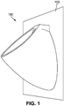
- Urinal 100 may be implemented in a restroom (e.g., public restroom, bathroom, washroom, powder room, etc.). As shown in FIG.
- urinal 100 is shown mounted to (e.g., attached to, coupled to, etc.) a surface, shown as wall 102. While only one urinal 100 is shown mounted to wall 102, additional urinals 100 may also be mounted to wall 102. For example, a series of urinals 100 may be equally spaced along wall 102. According to various embodiments, urinal 100 is mounted to wall 102 such that urinal 100 is substantially flush with wall 102.
- urinal 100 includes a first assembly, shown as bowl assembly 200, a second assembly, shown as trapway assembly 202, a third assembly, shown as mounting assembly 204, and a fourth assembly, shown as coupling assembly 206.
- Bowl assembly 200 is configured to receive liquid (e.g., urine, human waste, water, etc.).
- Bowl assembly 200 is also configured to receive trapway assembly 202.
- Trapway assembly 202 is configured to receive the liquid from bowl assembly 200 and to provide the liquid to a conduit (e.g., fluid return, pipe, outlet, etc.), shown as drain 208.
- Trapway assembly 202 is separate from bowl assembly 200 and is not integrated in bowl assembly 200. Drain 208 may ultimately provide the liquid to a receptacle (e.g., septic tank, storage tank, etc.) or to a treatment facility.
- a receptacle e.g., septic tank, storage tank, etc.
- Coupling assembly 206 is configured to selectively secure bowl assembly 200 to trapway assembly 202. According to various embodiments, coupling assembly 206 interfaces with trapway assembly 202 through bowl assembly 200. Coupling assembly 206 may be configured to minimize leakage of the liquid as it is provided from bowl assembly 200 to trapway assembly 202. In some applications, coupling assembly 206 may be removed for cleaning of coupling assembly 206 and/or trapway assembly 202.
- Bowl assembly 200 includes a frame (e.g., shell, case, etc.), shown as body 210.
- Body 210 may be constructed from various materials such as vitreous china, plastic (e.g., polymers, thermoplastics, resins, etc.), porcelain, metals (e.g., aluminum, etc.), ceramics, and other similar materials.
- body 210 may be constructed through various processes such as casting, molding (e.g., injection molding, etc.), forming, and other similar processes.
- Body 210 may be coated with various paints, enamels, surface treatments (e.g., anti-microbial treatments, anodizing, etc.), and other similar coatings. Different portions of body 210 may be coated with different coatings.
- body 210 may have different shapes. For example, body 210 may be rounded, elongated, curved, contoured, edged, or otherwise shaped.
- Body 210 defines a receptacle, shown as bowl 212.
- Bowl 212 may be configured to facilitate reception of liquid and transmission of the liquid to trapway assembly 202.
- bowl 212 is configured to maximize transmission of the liquid to trapway assembly 202 via gravitational forces.
- bowl 212 is coated with a coating configured to maximize transmission of the liquid to trapway assembly 202, such as a hydrophobic coating.
- Bowl 212 defines an opening, shown as opening 214.
- opening 214 is located at the bottom-most point of bowl 212.
- opening 214 is configured to receive coupling assembly 206.
- opening 214 is additionally or alternatively configured to receive trapway assembly 202.
- body 210 is substantially continuous (e.g., seamless, etc.). Because trapway assembly 202 is separate from bowl assembly 200, body 210 does not have any recesses for receiving fasteners that couple trapway assembly 202 to drain 208 or bowl assembly 200. Additionally, because mounting assembly 204 does not use fasteners to couple bowl assembly 200 to wall 102, body 210 does not have any recesses for receiving fasteners that couple bowl assembly 200 to wall 102. As a result, body 210 is easier to clean than conventional urinals that include these recesses. Body 210 may also be less prone to vandalism than conventional urinals that include these recesses.
- Body 210 also defines a cavity, shown as cavity 216. Cavity 216 is configured to receive trapway assembly 202.
- urinal 100 is removed (e.g., decoupled, etc.) from wall 102
- coupling assembly 206 is first decoupled from trapway assembly 202 and then removed.
- bowl assembly 200 is decoupled from mounting assembly 204.
- trapway assembly 202 remains coupled to drain 208. This allows liquid in trapway assembly 202 to remain substantially undisturbed as bowl assembly 200 is removed.
- conventional urinals utilize built-in (e.g., stuck on, integral, etc.) trapways.
- Cavity 216 may be oversized relative to trapway assembly 202. This may help to ensure that liquid in trapway assembly 202 remains substantially undisturbed. Cavity 216 may be configured to minimize weight of urinal 100. Similarly, cavity 216 may be symmetrical about a vertical, bisecting plane that is orthogonal to wall 102. In this way, cavity 216 may facilitate balancing of bowl assembly 200 on mounting assembly 204. Additionally, cavity 216 may be configured to optimize weight distribution on mounting assembly 204 and trapway assembly 202 such that bowl assembly 200 may be optimally secured on wall 102.
- Cavity 216 defines an opening (e.g., slot, hole, port, etc.), shown as receiver 218, and a surface (e.g., face, panel, etc.), shown as lower surface 220.
- Receiver 218 is configured to interface with mounting assembly 204 to support bowl assembly 200 on wall 102. According to various embodiments, receiver 218 is configured to interface with mounting assembly 204 without the use of fasteners. In some embodiments, receiver 218 is structurally integrated (e.g., molded, cast, formed, etc.) in body 210.
- lower surface 220 is configured to interface with trapway assembly 202.
- the interaction between lower surface 220 and trapway assembly 202 may assist mounting assembly 204 in supporting bowl assembly 200. Further, this interaction may assist bowl assembly 200 in coupling to mounting assembly 204. For example, as lower surface 220 contacts trapway assembly 202, mounting assembly 204 may be inserted into receiver 218.
- Trapway assembly 202 includes a conduit (e.g., pipe, etc.), shown as trapway 222, having a first end (e.g., connector, coupler, etc.), shown as inlet fitting 224, and a second end (e.g., connector, coupler, etc.), shown as outlet fitting 226.
- trapway 222 is generally U-shaped.
- inlet fitting 224 is configured to interface with coupling assembly 206
- outlet fitting 226 is configured to interface with drain 208.
- the shape, size, diameter, and configuration of trapway 222, inlet fitting 224, and outlet fitting 226 may be varied such that urinal 100 is tailored for a target application.
- Trapway assembly 202 also includes a body (e.g., frame, etc.), shown as trapway structure 228.
- Trapway structure 228 may provide rigidity to trapway 222.
- trapway 222 is integrated within trapway structure 228.
- trapway structure 228 includes an extension, shown as extension 230.
- Extension 230 is configured to interface with lower surface 220.
- extension 230 is shaped to substantially align inlet fitting 224 with opening 214 through this interaction.
- extension 230 may support bowl assembly 200 through the interaction between lower surface 220 and extension 230. Extension 230 may cause inlet fitting 224 to come into contact with, or to protrude from, opening 214.
- Extension 230 may be shaped to facilitate a target interaction between mounting assembly 204 and receiver 218.
- extension 230 may be shaped such that mounting assembly 204 is guided into receiver 218 according to a target trajectory.
- extension 230 may be shaped to match a contour of lower surface 220.
- extension 230 may be shaped to facilitate a target interaction between opening 214 and inlet fitting 224.
- extension 230 may be shaped such that as bowl assembly 200 is brought into confronting relation with wall 102, extension 230 contacts lower surface 220 such that inlet fitting 224 is guided towards opening 214 causing inlet fitting 224 to be located proximate opening 214 and/or aligned with opening 214 when bowl assembly 200 is coupled to wall 102 (e.g., when bracket 232 is received within receiver 218, etc.).
- Mounting assembly 204 includes a member, shown as bracket 232.
- Bracket 232 is configured to be secured to wall 102 and to be received in receiver 218.
- bracket 232 is secured to wall 102 through the use of fasteners (e.g., screws, nails, bolts, etc.).
- bracket 232 is secured to wall 102 through the use of adhesive (e.g., glue, resin, tape, etc.).
- bracket 232 is substantially aligned with drain 208.
- Mounting assembly 204 may include a plurality of brackets 232.
- mounting assembly 204 may include two brackets 232, each spaced an equal distance from drain 208 and on either side of drain 208.
- cavity 216 includes a corresponding number of brackets 232 configured to be substantially aligned with brackets 232 when bowl assembly 200 is coupled to mounting assembly 204.
- urinal 100 does not include mounting assembly 204.
- urinal 100 may be secured to wall 102 through the use of fasteners through body 210.
- wall 102 includes bracketry configured to receive urinal 100.
- wall 102 may include bracketry from a previously installed urinal such that the bracketry can be reused to secure urinal 100 to wall 102.
- coupling assembly 206 includes a fitting, shown as coupler 234, and a strainer (e.g., grate, top, etc.), shown as strainer 236.
- opening 214 is configured to partially receive coupler 234 and coupler 234 is configured to interface with inlet fitting 224 such that bowl 212 is positioned between coupler 234 and inlet fitting 224.
- coupler 234 is configured to threadably engage inlet fitting 224.
- coupler 234 is press fit, snap fit, interference fit, or otherwise coupled to inlet fitting 224. The diameter, length, and other similar characteristics of coupler 234 may be varied such that urinal 100 is tailored for a target application.
- Strainer 236 is configured to be received in coupler 234.
- strainer 236 may be secured to coupler 234 through a threaded interface, press fit, snap fit, interference fit, or otherwise secured to coupler 234.
- strainer 236 is configured to be removable to facilitate cleaning or urinal 100.
- strainer 236 may be removable via a tool-less interface.
- Strainer 236 may be interchangeable such that urinal 100 may be tailored for a target application.
- coupling assembly 206 does not include strainer 236.
- strainer 236 is integrated in (e.g., built into, etc.) coupler 234.
- urinal 100 does not include coupling assembly 206.
- coupler 234 and strainer 236 may be integrated in (e.g., built into, etc.) bowl assembly 200.
- inlet fitting 224 is configured to interface with, and extend from, opening 214.
- inlet fitting 224 may be press fit, snap fit, interference fit, or otherwise interfaced with opening 214.
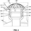
- a first seal shown as lower seal 238, and a second seal, shown as upper seal 240, are utilized in the interface between inlet fitting 224, bowl 212, and coupler 234 to prevent leakage of liquid.
- Lower seal 238 and upper seal 240 may be O-rings.
- lower seal 238 and upper seal 240 are compressible. According to an exemplary embodiment, lower seal 238 is located between inlet fitting 224 and bowl 212, and upper seal 240 is located between coupler 234 and bowl 212.
- coupler 234 includes a threaded pattern configured to interface with a threaded pattern inside of inlet fitting 224.
- upper seal 240 is compressed between coupler 234 and bowl 212
- lower seal 238 is compressed between a flange of inlet fitting 224, shown as flange 400, and bowl 212.
- a seal, shown as auxiliary seal 402 may be located inside of inlet fitting 224.
- Auxiliary seal 402 may interface with coupler 234 when coupler 234 is received in inlet fitting 224.
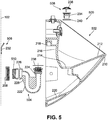
- Urinal 500 As shown in FIGS. 5 and 6 , a urinal, shown as urinal 500, is shown as an alternative to urinal 100 as previously described.
- Urinal 500 includes a first assembly, shown as bowl assembly 502, a second assembly, shown as trapway assembly 504, a third assembly, shown as mounting assembly 506, and a fourth assembly, shown as coupling assembly 508.
- Urinal 500 partly differentiates from urinal 100 in that trapway assembly 504 includes a connector, shown as union 510, that couples drain 208 to outlet fitting 226. The interaction between union 510, drain 208, and outlet fitting 226 may expedite removal and/or replacement of trapway assembly 504 (e.g., such as occurs when trapway assembly 504 is removed for servicing, etc.).
- union 510, drain 208, and outlet fitting 226 cooperate such that a full rotation of trapway assembly 504 is not required to decouple outlet fitting 226 from drain 208. This may substantially prevent contents within trapway assembly 504 from spilling out of trapway assembly 504 when trapway assembly 504 is removed for servicing. Additionally, union 510 maintains a spacing between wall 102 and outlet fitting 226. Trapway assembly 504 is shown to include trapway structure 228 as previously described but without extension 230. However, in other embodiments, trapway assembly 504 may include extension 230 as previously described.
- urinal 100 receives liquid (e.g., from a conduit in wall 102 and selectively provides the liquid to bowl 212 (e.g., in response to flush command, etc.). In these embodiments, urinal 100 does not utilize the liquid with every use of urinal 100, as would be done in a non-waterless urinal, but rather uses the liquid for regular flushes of urinal 100.
- wall 102 provides urinal 100 with an auxiliary connection (e.g., electrical connection, etc.). For example, wall 102 may provide urinal 100 electricity for powering devices on urinal 100 (e.g., motion detectors, illumination detectors, etc.).
- Various components of urinal 100 may be constructed of various materials such as brass, aluminum, polymeric material, thermoset, polymeric based blend, polymer, nylon, rubber, synthetic rubber, polyvinyl chloride, polytetrafluoroethylene, ceramic, ceramic blend, ceramic-metallic blend, vitreous china, alumina, metallic blend, zinc, alloy, brass, aluminum, steel, or any other suitable material such that urinal 100 may be tailored for a target application.
- exemplary is used to mean serving as an example, instance, or illustration. Any embodiment or design described herein as "exemplary” is not necessarily to be construed as preferred or advantageous over other embodiments or designs (and such term is not intended to connote that such embodiments are necessarily extraordinary or superlative examples). Rather, use of the word "exemplary” is intended to present concepts in a concrete manner. Accordingly, all such modifications are intended to be included within the scope of the present disclosure. Other substitutions, modifications, changes, and omissions may be made in the design, operating conditions, and arrangement of the preferred and other exemplary embodiments without departing from the scope of the appended claims.
- Coupled means the joining of two members directly or indirectly to one another. Such joining may be stationary (e.g., permanent) or moveable (e.g., removable or releasable). Such joining may be achieved with the two members or the two members and any additional intermediate members being integrally formed as a single unitary body with one another or with the two members or the two members and any additional intermediate members being attached to one another.
- any element e.g., trapway 222, coupler 234, etc.
- any other embodiment disclosed herein may be incorporated or utilized with any other embodiment disclosed herein.
- the order or sequence of any process or method steps may be varied or re-sequenced according to alternative embodiments.
- Any means-plus-function clause is intended to cover the structures described herein as performing the recited function and not only structural equivalents but also equivalent structures.
- Other substitutions, modifications, changes, and omissions may be made in the design, operating configuration, and arrangement of the preferred and other exemplary embodiments without departing from the scope of the appended claims.
Landscapes
- Health & Medical Sciences (AREA)
- Life Sciences & Earth Sciences (AREA)
- Engineering & Computer Science (AREA)
- Hydrology & Water Resources (AREA)
- Public Health (AREA)
- Water Supply & Treatment (AREA)
- Sanitary Device For Flush Toilet (AREA)
Applications Claiming Priority (1)
| Application Number | Priority Date | Filing Date | Title |
|---|---|---|---|
| US201762559341P | 2017-09-15 | 2017-09-15 |
Publications (1)
| Publication Number | Publication Date |
|---|---|
| EP3460132A1 true EP3460132A1 (de) | 2019-03-27 |
Family
ID=63556227
Family Applications (1)
| Application Number | Title | Priority Date | Filing Date |
|---|---|---|---|
| EP18193505.7A Withdrawn EP3460132A1 (de) | 2017-09-15 | 2018-09-10 | Urinal mit siphonweganschlusssystem |
Country Status (3)
| Country | Link |
|---|---|
| US (1) | US11111663B2 (de) |
| EP (1) | EP3460132A1 (de) |
| CN (1) | CN109505340B (de) |
Families Citing this family (5)
| Publication number | Priority date | Publication date | Assignee | Title |
|---|---|---|---|---|
| USD1018804S1 (en) * | 2020-12-23 | 2024-03-19 | Kohler India Corporation Private Limited | Urinal |
| USD1018803S1 (en) * | 2020-12-23 | 2024-03-19 | Kohler India Corporation Private Limited | Urinal |
| CN219753394U (zh) * | 2023-05-30 | 2023-09-26 | 科勒(中国)投资有限公司 | 一种排污结构及小便器 |
| DE102023115325A1 (de) * | 2023-06-13 | 2024-12-19 | Duravit Aktiengesellschaft | Sanitäreinrichtung |
| US20250075486A1 (en) * | 2023-08-28 | 2025-03-06 | Nathan Dick | Urinal Device |
Citations (5)
| Publication number | Priority date | Publication date | Assignee | Title |
|---|---|---|---|---|
| WO2002013668A1 (es) * | 2000-08-10 | 2002-02-21 | Eduardo Quintero Alvarez | Orinal ecologico que no usa agua |
| EP1335076A1 (de) * | 2002-02-11 | 2003-08-13 | Geberit Technik Ag | Ablaufarmatur für eine Sanitärvorrichtung, insbesondere Urinal |
| WO2007027801A2 (en) * | 2005-08-30 | 2007-03-08 | Zurn Industries, Inc. | Urinal |
| WO2009092201A1 (zh) * | 2007-12-27 | 2009-07-30 | Shanghai Kohler Electronics, Ltd. | 自动感应小便斗 |
| WO2013064262A1 (de) * | 2011-11-05 | 2013-05-10 | John Reese | S - förmiges siphonrohr mit einer trennwand |
Family Cites Families (11)
| Publication number | Priority date | Publication date | Assignee | Title |
|---|---|---|---|---|
| US931941A (en) * | 1909-08-24 | Patrick J Madden | Plumbing-fixture. | |
| DE4120768C2 (de) | 1991-06-24 | 2001-02-15 | Duravit Ag | Wandurinal |
| NL9102014A (nl) | 1991-11-29 | 1993-06-16 | Koninkl Sphinx Nv | Urinoir met bevestigingsbeugel. |
| DE50213420D1 (de) | 2001-04-06 | 2009-05-20 | Geberit Technik Ag | Geruchsverschluss für ein wasserloses Urinal |
| ZA200509145B (en) | 2004-11-15 | 2006-08-30 | Caroma Ind Ltd | A removable cartridge assembly for a waterless urinal |
| EP1785077A1 (de) | 2005-11-12 | 2007-05-16 | Bob W. Illy | Wasserloses Urinal |
| BRPI0920017A2 (pt) | 2008-10-06 | 2016-08-30 | Coflex Sa De Cv | aparelho de flange e método para conectar uma descarga de aparelho sanitário a um cano de escoamento de refugo |
| DE102009055977A1 (de) | 2009-11-27 | 2011-06-01 | Duravit Ag | Sanitäreinrichtung sowie Halterung zum Befestigen einer Sanitäreinrichtung |
| US8572768B2 (en) * | 2010-01-06 | 2013-11-05 | Fernco, Inc. | Urinal seal and method of installation |
| DE102010046698A1 (de) | 2010-09-28 | 2012-03-29 | Udo Wagner | Urinal |
| CN202187413U (zh) | 2011-07-05 | 2012-04-11 | 科勒(中国)投资有限公司 | 小便器虹吸排污管 |
-
2018
- 2018-09-04 US US16/120,613 patent/US11111663B2/en active Active
- 2018-09-10 EP EP18193505.7A patent/EP3460132A1/de not_active Withdrawn
- 2018-09-12 CN CN201811061380.4A patent/CN109505340B/zh active Active
Patent Citations (5)
| Publication number | Priority date | Publication date | Assignee | Title |
|---|---|---|---|---|
| WO2002013668A1 (es) * | 2000-08-10 | 2002-02-21 | Eduardo Quintero Alvarez | Orinal ecologico que no usa agua |
| EP1335076A1 (de) * | 2002-02-11 | 2003-08-13 | Geberit Technik Ag | Ablaufarmatur für eine Sanitärvorrichtung, insbesondere Urinal |
| WO2007027801A2 (en) * | 2005-08-30 | 2007-03-08 | Zurn Industries, Inc. | Urinal |
| WO2009092201A1 (zh) * | 2007-12-27 | 2009-07-30 | Shanghai Kohler Electronics, Ltd. | 自动感应小便斗 |
| WO2013064262A1 (de) * | 2011-11-05 | 2013-05-10 | John Reese | S - förmiges siphonrohr mit einer trennwand |
Also Published As
| Publication number | Publication date |
|---|---|
| CN109505340B (zh) | 2021-04-23 |
| US20190085549A1 (en) | 2019-03-21 |
| CN109505340A (zh) | 2019-03-22 |
| US11111663B2 (en) | 2021-09-07 |
Similar Documents
| Publication | Publication Date | Title |
|---|---|---|
| US11111663B2 (en) | Urinal with trapway connection system | |
| CA2836429C (en) | Compression drain with adjustable-height grate | |
| CA1315491C (en) | Sanitary fixtures | |
| US9068333B2 (en) | Connection and support structure for wall mounted sanitary devices such as toilets etc | |
| US20120036697A1 (en) | Methods for installing drainable structures with concealed drains | |
| US9732507B2 (en) | Wall-hung toilet with improved load-bearing capacity | |
| WO2012021601A2 (en) | Cover for concealed drain | |
| WO2012021616A2 (en) | Kits from which may be manufactured drainable structures with concealed drains | |
| CN102469898A (zh) | 浴室附属装置安装系统 | |
| CN113175035B (zh) | 水槽系统 | |
| US20100125935A1 (en) | Toilet and toilet seat mounting system | |
| CA2976189C (en) | Plumbing apparatus for connecting a tail piece to a waste pipe | |
| CA2431729A1 (en) | Shower apparatus for seated occupant | |
| GB2298661A (en) | Water trap | |
| EP1168955A1 (de) | Befestigungseinheit | |
| CN217027912U (zh) | 一种整体卫浴的管井检修口结构 | |
| CA2358171A1 (en) | Convertible shower | |
| US20030208841A1 (en) | Bath fitting and mounting thereof | |
| EP2365142B1 (de) | Geruchsverschluss mit zwei Montagevorrichtungen | |
| US20250129588A1 (en) | Toilet shell | |
| KR200305381Y1 (ko) | 조립식 욕실용 배수장치 | |
| EP4296440A1 (de) | Badezimmersystem | |
| AU2008100320A4 (en) | Drain Mate | |
| GB2431936A (en) | Method and apparatus for freely positioning a shower drain unit | |
| EP1500364A2 (de) | Verbindungsanordnung |
Legal Events
| Date | Code | Title | Description |
|---|---|---|---|
| PUAI | Public reference made under article 153(3) epc to a published international application that has entered the european phase |
Free format text: ORIGINAL CODE: 0009012 |
|
| STAA | Information on the status of an ep patent application or granted ep patent |
Free format text: STATUS: THE APPLICATION HAS BEEN PUBLISHED |
|
| AK | Designated contracting states |
Kind code of ref document: A1 Designated state(s): AL AT BE BG CH CY CZ DE DK EE ES FI FR GB GR HR HU IE IS IT LI LT LU LV MC MK MT NL NO PL PT RO RS SE SI SK SM TR |
|
| AX | Request for extension of the european patent |
Extension state: BA ME |
|
| STAA | Information on the status of an ep patent application or granted ep patent |
Free format text: STATUS: REQUEST FOR EXAMINATION WAS MADE |
|
| 17P | Request for examination filed |
Effective date: 20190918 |
|
| RBV | Designated contracting states (corrected) |
Designated state(s): AL AT BE BG CH CY CZ DE DK EE ES FI FR GB GR HR HU IE IS IT LI LT LU LV MC MK MT NL NO PL PT RO RS SE SI SK SM TR |
|
| STAA | Information on the status of an ep patent application or granted ep patent |
Free format text: STATUS: EXAMINATION IS IN PROGRESS |
|
| STAA | Information on the status of an ep patent application or granted ep patent |
Free format text: STATUS: THE APPLICATION HAS BEEN WITHDRAWN |
|
| 17Q | First examination report despatched |
Effective date: 20210324 |
|
| 18W | Application withdrawn |
Effective date: 20210407 |