EP3460167A1 - Fensterabdeckungssteuerungsvorrichtung - Google Patents
Fensterabdeckungssteuerungsvorrichtung Download PDFInfo
- Publication number
- EP3460167A1 EP3460167A1 EP17207347.0A EP17207347A EP3460167A1 EP 3460167 A1 EP3460167 A1 EP 3460167A1 EP 17207347 A EP17207347 A EP 17207347A EP 3460167 A1 EP3460167 A1 EP 3460167A1
- Authority
- EP
- European Patent Office
- Prior art keywords
- lift cord
- pulley
- ladder
- window covering
- rail
- Prior art date
- Legal status (The legal status is an assumption and is not a legal conclusion. Google has not performed a legal analysis and makes no representation as to the accuracy of the status listed.)
- Withdrawn
Links
Images



Classifications
-
- E—FIXED CONSTRUCTIONS
- E06—DOORS, WINDOWS, SHUTTERS, OR ROLLER BLINDS IN GENERAL; LADDERS
- E06B—FIXED OR MOVABLE CLOSURES FOR OPENINGS IN BUILDINGS, VEHICLES, FENCES OR LIKE ENCLOSURES IN GENERAL, e.g. DOORS, WINDOWS, BLINDS, GATES
- E06B9/00—Screening or protective devices for wall or similar openings, with or without operating or securing mechanisms; Closures of similar construction
- E06B9/24—Screens or other constructions affording protection against light, especially against sunshine; Similar screens for privacy or appearance; Slat blinds
- E06B9/26—Lamellar or like blinds, e.g. venetian blinds
- E06B9/28—Lamellar or like blinds, e.g. venetian blinds with horizontal lamellae, e.g. non-liftable
- E06B9/30—Lamellar or like blinds, e.g. venetian blinds with horizontal lamellae, e.g. non-liftable liftable
- E06B9/32—Operating, guiding, or securing devices therefor
- E06B9/322—Details of operating devices, e.g. pulleys, brakes, spring drums, drives
-
- E—FIXED CONSTRUCTIONS
- E06—DOORS, WINDOWS, SHUTTERS, OR ROLLER BLINDS IN GENERAL; LADDERS
- E06B—FIXED OR MOVABLE CLOSURES FOR OPENINGS IN BUILDINGS, VEHICLES, FENCES OR LIKE ENCLOSURES IN GENERAL, e.g. DOORS, WINDOWS, BLINDS, GATES
- E06B9/00—Screening or protective devices for wall or similar openings, with or without operating or securing mechanisms; Closures of similar construction
- E06B9/24—Screens or other constructions affording protection against light, especially against sunshine; Similar screens for privacy or appearance; Slat blinds
- E06B9/26—Lamellar or like blinds, e.g. venetian blinds
- E06B9/28—Lamellar or like blinds, e.g. venetian blinds with horizontal lamellae, e.g. non-liftable
- E06B9/30—Lamellar or like blinds, e.g. venetian blinds with horizontal lamellae, e.g. non-liftable liftable
- E06B9/303—Lamellar or like blinds, e.g. venetian blinds with horizontal lamellae, e.g. non-liftable liftable with ladder-tape
- E06B9/307—Details of tilting bars and their operation
-
- E—FIXED CONSTRUCTIONS
- E06—DOORS, WINDOWS, SHUTTERS, OR ROLLER BLINDS IN GENERAL; LADDERS
- E06B—FIXED OR MOVABLE CLOSURES FOR OPENINGS IN BUILDINGS, VEHICLES, FENCES OR LIKE ENCLOSURES IN GENERAL, e.g. DOORS, WINDOWS, BLINDS, GATES
- E06B9/00—Screening or protective devices for wall or similar openings, with or without operating or securing mechanisms; Closures of similar construction
- E06B9/24—Screens or other constructions affording protection against light, especially against sunshine; Similar screens for privacy or appearance; Slat blinds
- E06B9/26—Lamellar or like blinds, e.g. venetian blinds
- E06B9/28—Lamellar or like blinds, e.g. venetian blinds with horizontal lamellae, e.g. non-liftable
- E06B9/30—Lamellar or like blinds, e.g. venetian blinds with horizontal lamellae, e.g. non-liftable liftable
- E06B9/303—Lamellar or like blinds, e.g. venetian blinds with horizontal lamellae, e.g. non-liftable liftable with ladder-tape
- E06B9/308—Lamellar or like blinds, e.g. venetian blinds with horizontal lamellae, e.g. non-liftable liftable with ladder-tape with coaxial tilting bar and raising shaft
-
- E—FIXED CONSTRUCTIONS
- E06—DOORS, WINDOWS, SHUTTERS, OR ROLLER BLINDS IN GENERAL; LADDERS
- E06B—FIXED OR MOVABLE CLOSURES FOR OPENINGS IN BUILDINGS, VEHICLES, FENCES OR LIKE ENCLOSURES IN GENERAL, e.g. DOORS, WINDOWS, BLINDS, GATES
- E06B9/00—Screening or protective devices for wall or similar openings, with or without operating or securing mechanisms; Closures of similar construction
- E06B9/24—Screens or other constructions affording protection against light, especially against sunshine; Similar screens for privacy or appearance; Slat blinds
- E06B9/26—Lamellar or like blinds, e.g. venetian blinds
- E06B9/28—Lamellar or like blinds, e.g. venetian blinds with horizontal lamellae, e.g. non-liftable
- E06B9/30—Lamellar or like blinds, e.g. venetian blinds with horizontal lamellae, e.g. non-liftable liftable
- E06B9/32—Operating, guiding, or securing devices therefor
- E06B9/322—Details of operating devices, e.g. pulleys, brakes, spring drums, drives
- E06B2009/3222—Cordless, i.e. user interface without cords
Definitions
- the present innovation relates to window coverings.
- the present innovation relates to window coverings, ladder cord control mechanisms, and methods of utilizing such window coverings and/or mechanisms.
- Window coverings can be configured so that a material is moveable to partially or fully cover a window.
- Window coverings such as venetian blinds can utilize slats that are tiltable.
- Other types of window coverings can include other types of window covering material (e.g. cordless cellular shades, cordless Roman shades, etc.). Examples of such window coverings can be appreciated from U.S Patent Nos.
- Other examples of window coverings can be appreciated from co-pending U.S. Patent Application Nos. 15/672,442 , 15/659,943 , 15/185,400 , and 15/177,575 .
- Such window coverings can often include operator cords that extend from a cord lock and also include a tilt wand.
- the tilt wand often has to be rotated by a user to effect tilting of the slats.
- the cord lock is often utilized to control the vertical height adjustment of the blind.
- the window covering can be configured as a cordless window covering that does not have any exposed operator cord and also does not include any exposed tilt wand or other exposed slat tilting control element.
- the window covering can include exposed lift cords, an exposed operator cord and/or operator wand.
- a window covering can include a first rail and window covering material comprising a plurality of slats being moveable relative to the first rail.
- a lift cord control mechanism can be positioned in the first rail.
- the lift cord control mechanism can include a drive shaft that extends within the first rail.
- a first lift cord pulley can be connected to the drive shaft such that rotation of the drive shaft in a first rotational direction causes the first lift cord pulley to rotate in the first rotational direction and rotation of the first lift cord pulley in a second rotational direction that is opposite the first rotational direction causes the drive shaft to rotate in the second rotational direction.
- a first ladder cord connector can be connected to a first end of the first lift cord pulley to define a first slot between the first ladder cord connector and the first lift cord pulley.
- a first ladder can include a front rail, a rear rail, and rungs extending between the front and rear rails. Each of the rungs of the first ladder can support a respective one of the slats (e.g. at least partially support a slat or support a first end or side of a slat).
- the front rail can be moveable relative to the rear rail to adjust an orientation of the rungs between tilted orientations and a horizontal orientation.
- An upper end of the first ladder can be defined by a connection between an upper end of the front rail and an upper end of the rear rail.
- the upper end of the first ladder can be positioned in the first slot between the first ladder cord connector and the first lift cord pulley so that rotation of the drive shaft in the first rotational direction moves the first ladder so that the rungs are moveable into a first tilted orientation (e.g. inclined or declined orientation) for tilting of the slats and rotation of the drive shaft in the second rotational direction moves the first ladder so that the rungs are moveable into a second tilted orientation for tilting of the slats (e.g. an inclined or declined orientation that is tilted opposite the tilting of the first tilted orientation).
- a first tilted orientation e.g. inclined or declined orientation
- a first lift cord can extend from the first lift cord pulley to a position adjacent a bottom-most slat of the slats supported by a bottommost rung of the rungs of the first ladder.
- the first lift cord can be connected to the first lift cord pulley such that rotation of the first lift cord pulley in the first rotational direction winds the first lift cord about the first lift cord pulley to facilitate retraction of the window covering material and rotation of the first lift cord pulley in the second rotational direction unwinds the first lift cord from the first lift cord pulley to facilitate extension of the window covering material.
- Embodiments of the window covering can be configured so that the first rail is a headrail or the middle rail of a top down bottom up shade.
- a second rail can also be included as a bottom rail.
- the second rail can be connected adjacent to the bottom-most rung and the bottom-most slat via a connection to one or more lift cords or attachment to the bottom -most slat or attachment to one or more ladders that can extend form the first rail.
- the drive shaft can be configured to extend through the first lift cord pulley and the first ladder cord pulley.
- the drive shaft can be positioned in the first rail so that it passes through a central channel of the first lift cord pulley that is aligned with a channel defined in the first ladder cord connector.
- the drive shaft can extend through the central channel of the first lift cord pulley and also extend through the channel defined in the first ladder cord connector.
- These channels can be configured so that the drive shaft is interlocked to the first lift cord pulley and the first ladder cord connector (e.g. the drive shaft has a cross-sectional shape that mates with the cross-sectional shape of the channels).
- the window covering can include other features.
- the window covering can also include a first end connector attached to a second end of the first lift cord pulley.
- the first lift cord can be collectable on a body of the first lift cord pulley between the first end connector and the first ladder cord connector via rotation of the first lift cord pulley in the first rotational direction (e.g. be wound upon the body of the first lift cord pulley via rotation in the first rotational direction).
- the first lift cord can also be uncollectable, or unwindable from the body of the first lift cord pulley between the first end connector and the first ladder cord connector via rotation of the first lift cord pulley in the second rotational direction (e.g.
- the first rotational direction can be clockwise and the second rotational direction can be counterclockwise in some embodiments. In other embodiments, the first rotational direction can be counterclockwise and the second rotational direction can be clockwise.
- the lift cord control mechanism of the window covering can include a number of different mechanisms.
- the lift cord control mechanism can include at least one spring motor unit.
- the lift cord control mechanism could be a loop cord drive, an electric motor, or another type of lift cord control mechanism.
- the lift cord control mechanism can include a first spring motor that includes a first spring motor pulley, a second spring motor pulley and a spring extending between the first spring motor pulley and the second spring motor pulley.
- the drive shaft can be connected to the first spring motor pulley.
- the spring can be configured to bias the first spring motor pulley to rotate in the first rotational direction.
- the window covering can also include mounting elements positioned in the first rail adjacent the first lift cord pulley.
- Each mounting element can include at least one friction inducing member for contacting a lift cord.
- a mounting element can include a first friction inducing member attached to the mounting element so that the first friction inducing member is not rotatable and the first lift cord contacts the first friction inducing member.
- the first lift cord can be routed along the first friction inducing member such that the first lift cord defines at least one full encirclement about the friction inducting member.
- a method for adjusting a window covering can include providing a window covering such as an embodiment of a window covering disclosed herein.
- a window covering can include, for example, a first rail; window covering material comprising a plurality of slats being moveable relative to the first rail, and a lift cord control mechanism positioned in the first rail.
- the lift cord control mechanism can have a drive shaft that extends within the first rail.
- the window covering can also include a first lift cord pulley connected to the drive shaft such that rotation of the drive shaft in a first rotational direction causes the first lift cord pulley to rotate in the first rotational direction and rotation of the first lift cord pulley in a second rotational direction that is opposite the first rotational direction causes the drive shaft to rotate in the second rotational direction, a first ladder cord connector connected to a first end of the first lift cord pulley to define a first slot between the first ladder cord connector and the first lift cord pulley, and a first ladder having a front rail, a rear rail, and rungs extending between the front rail and the rear rail. Each of the rungs of the first ladder can support a respective one of the slats.
- the front rail can be moveable relative to the rear rail to adjust an orientation of the rungs between tilted orientations and a horizontal orientation.
- An upper end of the first ladder can be defined by a connection between an upper end of the front rail and an upper end of the rear rail.
- the upper end of the first ladder can be positioned in the first slot between the first ladder cord connector and the first lift cord pulley so that rotation of the drive shaft in the first rotational direction moves the first ladder so that the rungs are moveable into a first tilted orientation for tilting of the slats and rotation of the drive shaft in the second rotational direction moves the first ladder so that the rungs are moveable into a second tilted orientation for tilting of the slats.
- a first lift cord can extend from the first lift cord pulley to a positioned adjacent a bottom-most slat of the slats supported by a bottommost rung of the rungs of the first ladder.
- the first lift cord can be connected to the first lift cord pulley such that rotation of the first lift cord pulley in the first rotational direction winds the first lift cord about the first lift cord pulley to facilitate retraction of the window covering material and rotation of the first lift cord pulley in the second rotational direction unwinds the first lift cord from the first lift cord pulley to facilitate extension of the window covering material.
- the method can also include providing a force to extend the window covering material so that the first lift cord is unwound from the first lift cord pulley and the first lift cord pulley rotates in the second rotational direction so that the drive shaft rotates in the second rotational direction and the rungs of the ladder are tilted so that the rungs are in the second tilted orientation and, after the providing of the force to extend the window covering material, providing a force to retract the window covering material until the rungs are in the horizontal orientation.
- the force that is provided to retract the window covering material can be a lifting force and the force that is provided to extend the window covering material can be a lowering force.
- the window covering material can be pulled to provide the force to extend the window covering material and the window covering material can be pushed to provide the force to retract the window covering material in some embodiments of the method.
- a spring motor of the lift cord control mechanism can rotate the drive shaft to rotate in the first rotational direction in response to the force that is provided to retract the window covering material. The rotation of the drive shaft in the first rotational direction can cause the lift cord pulley to rotate in the first rotational direction to retract the window covering material.
- the upper end of the first ladder can be positioned in the first slot between the first ladder cord connector and the first lift cord pulley so that rotation of the drive shaft in the first rotational direction moves the first ladder so that the rungs are moveable into a first tilted orientation for tilting of the slats and rotation of the drive shaft in the second rotational direction moves the first ladder so that the rungs are moveable into a second tilted orientation for tilting of the slats.
- a first lift cord can extend from the first lift cord pulley to a position adjacent a bottom-most slat of the slats supported by a bottommost rung of the rungs of the first ladder.
- the first lift cord can be connected to the first lift cord pulley such that rotation of the first lift cord pulley in the first rotational direction winds the first lift cord about the first lift cord pulley to facilitate retraction of the window covering material and rotation of the first lift cord pulley in the second rotational direction unwinds the first lift cord from the first lift cord pulley to facilitate extension of the window covering material.
- a second lift cord pulley can be connected to the drive shaft such that rotation of the drive shaft in a first rotational direction causes the second lift cord pulley to rotate in the first rotational direction and rotation of the second lift cord pulley in a second rotational direction that is opposite the first rotational direction causes the drive shaft to rotate in the second rotational direction.
- a second ladder cord connector can be connected to a first end of the second lift cord pulley to define a second slot between the second ladder cord connector and the second lift cord pulley.
- a second ladder can have a front rail, a rear rail, and rungs extending between front and rear rails where each of the rungs of the second ladder support a respective one of the slats adjacent a second side of the slats.
- the front rail can be moveable relative to the rear rail to adjust an orientation of the rungs between tilted orientations and a horizontal orientation.
- An upper end of the second ladder can be defined by a connection between an upper end of the front rail and an upper end of the rear rail of the second ladder.
- a second lift cord can extend from the second lift cord pulley to a positioned adjacent a bottom-most slat of the slats supported by a bottom-most rung of the rungs of the second ladder.
- the second lift cord can be connected to the second lift cord pulley such that rotation of the second lift cord pulley in the first rotational direction winds the second lift cord about the second lift cord pulley to facilitate retraction of the window covering material and rotation of the second lift cord pulley in the second rotational direction unwinds the second lift cord from the second lift cord pulley to facilitate extension of the window covering material.
- the window covering can also include a first mounting element positioned in the first rail adjacent the first lift cord pulley, a first friction inducing member attached to the first mounting element so that the first friction inducing member is not rotatable and is positioned below the first lift cord pulley such that the first lift cord contacts the first friction inducing member.
- a second mounting element can also be positioned in the first rail adjacent the second lift cord pulley.
- a second friction inducing member can be attached to the second mounting element so that the second friction inducing member is not rotatable and is positioned below the second lift cord pulley such that the second lift cord contacts the second friction inducing member.
- the first lift cord can be routed along the first friction inducing member such that the first lift cord defines at least one full encirclement about the first friction inducting member; and the second lift cord can be routed along the second friction inducing member such that the second lift cord defines at least one full encirclement about the second friction inducting member.
- Use of one or more encirclements can be utilized to induce a desired amount of friction during retraction or extension of the window covering material.
- the first mounting element can be configured to receive the first lift cord pulley and the first ladder cord connector and the second mounting element can be configured to receive the second lift cord pulley and the second ladder cord connector.
- the first and second mounting elements may be spaced apart from each other within the first rail so that the first and second lift cord pulleys are also spaced apart from each other.
- the first and second lift cord pulleys can be positioned such that the first and second ladder cord are each positioned closer to a center part of the first rail than the first and second lift cord pulleys or can be positioned so that the first and second ladder cord connectors are each positioned farther from the center part of the first rail than the first and second lift cord pulleys.
- embodiments of the window covering can include a height adjustment mechanism for controlling the raising and lowering of window covering material.
- Embodiments of the window covering can be configured to permit the window covering material to be raised and lowered without use of lift cords passing through a cord lock and/or without use of any exposed operator cord while also not utilizing any type of exposed slat tilt control element (e.g. a tilt wand).
- Other embodiments may include one or more exposed cords, such as exposed operator cords or exposed lift cords that may pass out of a cord lock.
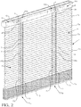
- Embodiments of the window covering 1 can include a first rail 3, a second rail 5, and window covering material 7 that is moveably attached to the first rail 3.
- the first rail 3 can be configured as a headrail and the second rail 5 can be configured as a bottom rail.
- the second rail 5 can be connected to the window covering material 7 and/or may be coupled to the first rail 3 such that the window covering material 7 and second rail 5 are moveable relative to the first rail 3.
- the window covering material 7 can be moveable between a fully lowered, or fully extended first position, and a fully retracted, or fully raised second position.
- the window covering material 7 can be connected to the first rail 3 via one or more lift cords 4 that are coupled to a lift cord control mechanism 10 so that the window covering material 7 is adjustably positioned in any number of other positions between the fully raised and fully lowered positions.
- the second rail 5 can also be connected to the lift cord control mechanism to be moved relative to the first rail as the window covering material position is adjusted.
- the lift cord control mechanism 10 can be considered a height adjustment mechanism for controlling the raising and lowering of window covering material 7 for at least some embodiments of the window covering 1.
- the lift cord control mechanism 10 can include a spring motor unit located in the first rail 3. In other embodiments, the lift cord control mechanism 10 can be positioned within the second rail 5.
- the lift cord control mechanism 10 can include a first spring motor 10a that includes spring motor pulleys 31 and a spring 32 that extends between the spring motor pulleys 31 such that the spring 32 is moveable between these pulleys to adjust an amount of force exerted on a drive shaft 10c to maintain a position of the lift cords for maintaining a position of the window covering material 7 at a user selected position.
- the spring motor pulleys 31 can be mounted within a housing 34 and the spring 32 can be positioned in the cavity of the housing 31.
- the housing can have at least one hole through which the drive shaft 10c is passable for a connection of the drive shaft 10c to a spring motor pulley 31.
- a first end of the drive shaft 10c can be connected to one of the spring motor pulleys 31 so that rotation of that spring motor pulley in a first rotational direction (e.g. clockwise or counterclockwise direction) drives rotation of the drive shaft 10c and rotation of the drive shaft 10c in a second rotational direction that is opposite the first rotational direction drives rotation of the spring motor pulley 31.
- the spring 32 is moved between the spring motor pulleys 31 during rotation of the drive shaft 10c in the first rotational direction and also moves in an opposite direction between the spring motor pulleys 31 when the drive shaft 10c is rotated in the second rotational direction.
- the first end of the drive shaft 10c can be connected within a channel or opening defined in the spring motor pulley 31 for providing a mating interlock between the drive shaft 10c and the spring motor pulley 31 for such a connection.
- a second spring motor 10b can be provided as well.
- the second spring motor 10b can be positioned at an opposite end of the first rail 3 from the first spring motor 10a.
- a spring motor pulley 31 of the second spring motor 10b can be connected to a second end of the drive shaft 10c in a manner similar to how the first spring motor 10a can be connected to the first end of the drive shaft 10c.
- the second spring motor 10b may be positioned at the same side of the first rail 3 as the first spring motor 10a and a portion of the drive shaft 10c can pass through a spring motor pulley 31 in each of the spring motors via an interlocking connection between the drive shaft 10c and a central channel of spring motor pulleys 31 to provide the coupling of the spring motors to the drive shaft 10c.
- the window covering material 7 can include slats 7a that are supported on ladders 71.
- the ladders 71 can each include a front rail 72 adjacent a front face of the window covering material and a rear rail 72 adjacent a rear face of the window covering material.
- Rungs 74 can extend between the front and rear rails 72 to support the slats 7a.
- there may be more than two ladders 71 such that at least one ladder supports a middle portion of the slats 7a between the right side and the left side of the slats.
- the slats 7a can be supported on the rungs 74 so that the slats are tiltable from a first closed position in which the slats are in an inclined orientation (e.g. the left and right ends of each slat extends along an angle of about 30-60° relative to horizontal and the rear edge of the slat is lower than the front edge of the slat), an open position in which the slats are in a horizontal orientation (e.g.
- the front and rear edges of the slats extend horizontally or extend within 5°-10° of being horizontal) and the left and right ends of the slats extend horizontally or extend within 5°-10° of being horizontal), and to a second closed position in which the slats are in a declined orientation (e.g. the left and right ends of each slat extends along an angle of about 30-60° relative to horizontal and the front edge of the slat is lower than the rear edge of the slat).
- each slat When the slats are in a closed position, a bottom edge of each slat may contact the top edge of an immediately adjacent lower slat or may overlap the top edge of an immediately adjacent lower slat to close a gap that is present between those slats when the slats are in their open position.
- the slats 7a may be exposed so that the slats are visible to a consumer and affect the aesthetic effect provided by the window covering 1.
- the slats 7a may be hidden from view or be partially hidden from view.
- the window covering material can also include pleated material, cellular material, fabric material, non-woven fabric material, woven wood, woven bamboo, or other type of material that may enclose or partially enclose the slats 7a.
- the slats 7a may be tiltable to effect how transparent or light-blocking the window covering material 7 may be.
- One or more lift cords 4 may extend from at least one pulley that is located within the first rail 3 through the window covering material 7 to connect the window covering material to the lift cord control mechanism 10.
- the one or more lift cords 4 may be directly connected to the window covering material.
- the one or more lift cords may be pass through the window covering material 7 and also be connected to the second rail 5 and/or pass through the second rail 5 to facilitate a connection of the lift cord control mechanism 10 to the window covering material 7 and the second rail 5.
- Some embodiments of the window covering 1 can include a first lift cord 27 and a second lift cord 29.
- Other embodiments may utilize more than two lift cords (e.g. three lift cords, four lift cords, five lit cords, six lift cords, etc.).
- Other embodiments may utilize only one cord that is manipulated via one or more pulleys or other mechanism to route that cord to provide two runs, or lines, to function as multiple lift cords.
- the middle portion of the cord may be coupled to the lift cord control mechanism 10 and the terminal ends of the cord can be connected to different sides or adjacent different ends of the second rail 5 or a lower portion of the window covering material 7.
- Each lift cord may be a cord, a segment of a cord, a tape, a polymeric filament, or other type of flexible elongated member.
- each lift cord 4 can be collected on and unwound from a respective pulley 12.
- Each pulley 12 can be connected to the drive shaft 10c so that the pulley is operatively connected to the lift cord control mechanism 10 (e.g. first and/or second spring motors 10a and 10b, etc.).
- a first end of the lift cord 4 can be connected to the pulley 12 and the lift cord can extend from the pulley 12 so that the opposite second end of the lift cord can be coupled to a bottommost slat 7 or the second rail 5.
- a window covering 1 can include a first lift cord pulley 12a and a second lift cord pulley 12b that are spaced apart from each other within the first rail 3.
- the first lift cord 27 can be collected on the first lift cord pulley 12a and extend form that pulley through or by the slats 7a and to the second rail 5.
- the second lift cord 29 can be collected on the second lift cord pulley 12b and extend form that pulley through or by the slats 7a and to the second rail 5.
- Each pulley 12 can have a similar structure, or configuration.
- each pulley 12 can be positioned on or in a mounting element 13 that is attached to or mounted in the first rail 3 such that the pulley 12 is rotatable in opposite rotational directions within the first rail (e.g. is rotatable in a clockwise direction and is also rotatable in a counter clockwise direction).
- the mounting element 13 can be configured as pulley housing, a pulley carriage or other type of pulley positioning mechanism to facilitate positioning of the pulley within the first rail 3.
- Each pulley 12 can have a body that defines an elongated central channel 12c that extends from a first end of the body of the pulley to a second end of the body of the pulley that is opposite its first end.
- the central channel can have openings at its opposite ends defined in opposite ends of the body of the pulley so that the drive shaft 10c can extend though the pulley so that rotation of the drive shaft 10c cause the pulley 12 to rotate (e.g. the cross section of channel 12c can interlock with the cross-sectional shape of the drive shaft 10c for engagement between the drive shaft 10c and the pulley 12).
- the opposite ends of the pulley can also be connected to other structures to facilitate coupling to the drive shaft 10c and to facilitate coupling to a ladder cord 71 that supports slats 7a.
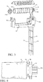
- each pulley 12 can be connected to an end connector 14 that has a projection 14a for being positioned in an aperture 13a (e.g. a slot) of a mounting element 13 to facilitate rotation of the pulley 12 in the first rail 3.
- the projection 14a may have a central channel that is aligned with the central channel 12c so that the drive shaft 10c can pass through the first end connector 14 and the pulley 12.
- the mounting element 13 can also include a second aperture 13b that is designed to retain a ladder cord connector 16 that has a projection 16a.
- the projection 16a of the ladder cord connector 16 can pass through a hole defined in the second aperture 13b that is in communication with a cavity that defines a receptacle of the mounting element that is for retaining the ladder cord connector 16.
- the projection 16a of the ladder cord connector 16 can include a central channel that is aligned with the central channel 12c of the pulley 12 so that the drive shaft 10c can pass through the end connector 14, pulley 12 and the ladder cord connector 16 via the central channel 12c and channels within the first connector 14 and the ladder cord connector 16.
- the lift cord pulleys 12 and ladder cord connectors 16 can be arranged in a number of different ways within the first rail.
- the ladder cord connectors 16 can be connected to ends of respective pulleys 12 so that the projections 16a of the ladder cord connectors 16 extend towards each other and the ladder cord connectors are closer to the center of the first rail than the pulleys 12.
- the ladder cord connectors 16 can be connected to the pulleys 12 such that the pulleys 12 are located closer to a center of the first rail 3 than the ladder cord connectors 16.
- a first ladder cord connector can be closer to a center of the first rail 3 than a second ladder cord connector and a first lift cord pulley can be farther from the center of the first rail 3 that a second lift cord pulley.
- Each pulley 12 can be connected to a respective ladder cord connector 16 to define a slot 18 in which an upper end of a ladder 71 is positioned.
- the ladder cord connector 16 can be connected to an end of the body of the pulley 12 so that a narrow slot 18 is defined between the pulley 12 and the ladder cord connector 16.
- the slot 18 can be structured so that an inner portion 18a of the slot 18 is narrower than an outer portion 18b of the slot 18.
- An upper end of a ladder cord can connected to the pulley 12 and ladder cord connector 16 via this slot 18.
- a top end of a ladder 71 defined by a ladder cord can be looped about the ladder cord connector and positioned in the slot 18 so that front and rear rails 72 of the ladder 71 extend along opposite sides (e.g. front and rear sides) of the slats 7a to the second rail 5.
- first and second lift cords 27 and 29 that are each collected on respective first and second lift cord pulleys 12a and 12b
- Embodiments of the window covering that have slats 7a supported on ladders 71 that can be configured so that the slats 7a are tiltable between open and closed positions in addition to being adjustable between raised and lowered positions, or retracted and extended positions.
- the window covering 1 can include slats 7a as its window covering material 7 and can have a first ladder 71a positioned adjacent a first side of the window covering and a second ladder 71b positioned adjacent a second side of the window covering to support the slats that are suspended from the first rail 3 via first and second ladders 71a and 71b and the lift cords 4.
- Each of the ladders 71 can have vertically spaced apart rungs 74 that extend between spaced apart front and rear rails 72 of the ladders 71.
- the font rails 72 of the ladders 71 can extend along affront face of the slats adjacent the front edges of the slats and the rear rails 72 of the ladder can extend along a rear face of the slats adjacent the rear edges of the slats 7a.
- a slat tilt control mechanism 20 can be operatively connected to the ladders 71 that support the slats to adjust the positions and/or orientations of the rails 72 and rungs 74 of the ladders to facilitate adjustment of the orientation of the slats between the open position and different closed positions.
- the slat tilt control mechanism 20 can include a first ladder control mechanism 20a and a second ladder control mechanism 20b that each include a slot 18 defined between a ladder cord connection pulley 16 attached to a pulley 12.
- the first ladder control mechanism 20a can include the slot 18 that receives the upper end or top end of the first ladder 71a between the ladder cord connector 16 and an end of the first lift cord pulley 12a and the second ladder control mechanism 20b can include the slot 18 that receives the upper end or top end of the second ladder 71b between the ladder cord connector 16 and an end of the second lift cord pulley 12b.
- the ladder control mechanism 20 can be configured to work in conjunction with the lift cord control mechanism 10 so that an adjustment in the orientation of the slats 7a and rungs 74 (e.g. tilting or moving from a tilted orientation to a horizontal orientation) occurs automatically and simultaneously with height adjustment of the window covering material 7 (e.g. retraction and extension of the window covering material 7).
- the window covering 1 can be configured so that each lift cord has a first portion positioned in the first rail 3, a second portion that passes through the window covering material 7, and a third portion that is positioned in the second rail 5.
- each of the lift cords can be configured to pass between the front and rear rails 74 of a respective ladder 71 or may pass alongside or adjacent a respective ladder 71 when extending from the first rail 3 to the second rail 5 or a bottom portion of the window covering material (e.g. the bottom most slat).
- the first lift cord 27 can have a first segment 27a that extends from the first rail 3, through the slats between the front and rear rails 72 of a first ladder 71 a to the second rail 5.
- the second lift cord 29 can have a first segment 29a that extends from the first rail 3, through the slats between the front and rear rails 72 of a second ladder 71b to the second rail 5.
- the lift cords can extend from the first rail 3 to the window covering material 7 by passing alongside front or rear edges of the slats adjacent to a front or rear rail of a ladder 71.
- the lift cords may not pass through any hole within any of the slats or may only pass through a recess or cut-out defined in outer edges of the slats 7a.
- the lift cords 4 can be passed through the window covering material so that motion of the one or more lift cords can result in retraction or extension of the window covering material 7 to raise or lower the window covering.
- a user may grasp the window covering material 7, the second rail 5, or a handle connected to the second rail 5 or the window covering material 7 to provide a downward force, or a puling force, that overcomes the biasing force provided by one or more springs 32 that act on the drive shaft 10c of the lift cord control mechanism 10 to lower the window covering material 7 and second rail 5.
- This force provided by the user to lower the window covering drives motion of the lift cords to effect the lowering, or extension, of the window covering material 7 and the lowering of the second rail 5 such that, during lowering of the window covering material, the pulleys 12 may rotate in the second rotational direction so that lift cords 4 are unwound from the pulleys due to the lowering of the window covering material 7, which also drives rotation of the drive shaft 10c due to the drive shaft's connection to the pulleys 12.
- the rotation of the drive shaft 10c causes the spring motor pulley(s) to which the drive shaft is attached to rotate in the same second rotational direction as the pulleys 12 and the drive shaft 10c such that the spring 32 moves between adjacent spring motor pulleys 31 to which the spring is connected.
- a user may provide a lifting force, or a pushing force, that is sufficient so that the biasing force of one or more springs 32 of the lift cord control mechanism 10 causes the lift cords to be moved to retract the window covering material 7 and second rail 5.
- the rotational force can be conveyed via at least one of the springs 32 moving between spring motor pulleys 31 to which it connected so that the spring motor pulley 31 connected to the drive shaft 10c rotates in the first rotational direction.
- the lift cord control mechanism 10 can be configured to counterbalance the weight of the window covering material 7 and second rail 5 to prevent rotation of the drive shaft 10c (and pulleys 12 connected to the drive shaft 10c) to keep the lift cords stationary after the user has removed the applied force to maintain the window covering material 7 and the second rail 5 at the user selected position of the window covering material 7 and the second rail 5.
- the pulleys 12 and ladder cord connectors 16 can be configured so that when the window covering material 7 is retracted, the rails 72 of the ladders move to tilt the orientation of the rungs 74 from a horizontal orientation to a declined orientation (or an inclined orientation to a declined orientation) so that the slats 7a are in a tilted position so that the window covering material can be moved to a closed position. After the window covering material 7 is moved to a desired position, the slats can be kept in this closed position. If the user desires to have the slat orientation adjusted so that the slats are no longer tilted and the window covering material is in an open position, the user may provide a force to slightly lower, or extend, the window covering material 7.
- Such a force will cause the pulleys 12 and ladder cord connectors 16 to rotate in an opposite direction so that the rails 72 of the ladders 71 move to change the orientation of the slats 7a.
- the slats 7a can be in their open positions so that the window covering material 7 is at a desired location and in the open position. The user may then remove the exerted force to keep the window covering material maintained at the desired position and in the open orientation (via the lift cord control mechanism 10 acting on the drive shaft 10c).
- Such a control of the positioning of the slats 7a can occur at the same time the window covering material 7 is retracted so that a separate slat tilt control actuator (e.g. a tilt wand) is not needed or used to adjust the slat orientation of the window covering material between their open and closed positions when the window covering material 7 is raised or retracted to a new position.
- a separate slat tilt control actuator e.g. a tilt wand
- the pulleys 12 and ladder cord connectors 16 can also be configured so that when the window covering material 7 is extended by a user, the rails 72 of the ladders 71 move to tilt the orientation of the rungs 74 to an inclined orientation.
- the rails 72 of the ladders can move to tilt the orientation of the rungs 74 from a horizontal orientation or a declined orientation to an inclined orientation so that the slats 7a are in a tilted position so that the window covering material can be moved to a closed position as it is extended. After the window covering material 7 is moved to a desired position, the slats can be kept in this closed position.
- the user may provide a force to slightly raise, or retract, the window covering material 7.
- a force will cause the pulleys 12 and ladder cord connectors 16 to rotate in an opposite direction so that the rails 72 of the ladders 71 move to change the orientation of the slats 7a.
- the slats 7a can be in their open positions so that the window covering material 7 is at a desired location and in the open position.
- the user may then remove the exerted force to keep the window covering material 7 maintained at the desired position and the slats 7a in their open orientation (via the lift cord control mechanism 10 acting on the drive shaft 10c).
- Such a control of the positioning of the slats 7a can occur at the same time the window covering material 7 is extended so that a separate slat tilt control actuator (e.g. a tilt wand) is not needed or used to adjust the slat orientation of the window covering material 7 between their open and closed positions during the extension, or lowering of the window covering material 7 to a new position.
- a separate slat tilt control actuator e.g. a tilt wand
- the rails 72 of the ladders 71 may only move a certain extent and then be kept (or maintained) at their new orientation while the pulleys 12 continue to rotate during widow covering material retraction.
- the rotational motion of the ladders 71 that is then subsequently stopped while further retraction of window covering material 7 occurs can be provided via the slot 18 and ladder cord connector 16 attachment to the pulley 12 that may be utilized for coupling each ladder 71 to a respective pulley 12.
- the upper end of the rails 72 may move between the pulley 12 and ladder cord connector 16 to which that ladder 71 is connected so that a rear rail 72 and front rail 72 of the ladder move relative to each other for orientation of the rungs 74 to a tilted position (e.g. inclined or declined orientation).
- the rails 72 may be kept in their same tilted orientation as the pulley 12 and ladder cord connector 16 continues to rotate simultaneously with the drive shaft 10c due to the upper ends of the rails 72 being integrally connected to define a loop 79 positioned in the slot 18.
- this loop 79 defined by the integral connection of the rails 72 may slip within the slot 18 so that the rails 72 extending from the opposite front and rear sides of the slot 18 defined between the ladder cord connector 16 and lift cord pulley 12 and rungs 74 maintain their orientation without the ladder 71 being collected on or unwound from the slot as the pulley 12 and ladder cord connector rotates during retraction.
- the rails 72 of the ladders 71 may only move a certain extent and then be kept (or maintained) at their new orientation while the pulleys 12 continue to rotate during widow covering material extension.
- the rotational motion of the ladders 71 that is then subsequently stopped while further extension of window covering material 7 occurs can be provided via the slot 18 and ladder cord connector 16 attachment to the pulley 12 that may be utilized for coupling each ladder 71 to a respective pulley 12.
- the upper end of the rails 72 for each ladder may move between the pulley 12 and ladder cord connector 16 to which the ladder 71 is connected so that a rear rail 72 and front rail 72 of the ladder 71 move relative to each other for orientation of the rungs 74 of the ladder.
- the rails 72 may be kept in their same orientation as the pulley 12 and ladder cord connector 16 to which the ladder 71 is connected continues to rotate simultaneously with the drive shaft 10c due to the upper ends of the rails 72 being integrally connected to define the loop 79 positioned in the slot 18.
- This loop may slip within the slot 18 so that the rails 72 no longer move relative to each other and the rungs 74 maintain their tilted orientation without the ladder 71 being collected on or unwound from the slot 18 as the pulley 12 and ladder cord connector 16 rotates during window covering material extension.
- the limited rotation of the ladders 71 can be provided via a connection that may be defined between the respective mounting element 13 and the ladder cord connector 16 to which a ladder 71 is coupled.
- the second aperture 13b can be configured to limit rotational motion of the ladder cord connector 16 so that it is only able to rotate a limited amount.
- the ladder cord connector 16 can also be connected to the drive shaft 10c and pulley 12 such that the ladder cord connector 16 is able to no longer rotate without affecting the rotational motion of the pulley 12 and drive shaft 10c.
- Such a feature can be provided via a slip-type connection that may be defined between the drive shaft 10c and the ladder cord connector 16 (e.g.
- Each of the mounting elements 13 can be configured to facilitate the routing of lift cords 4 as they extend from the pulleys 4 to induce friction that affects motion of the lift cords during extension and also during retraction of window covering material. This added friction can help provide an additional amount of force to help provide a more precise amount of window covering material position control via the lift cord control mechanism 10.
- each mounting element 13 can be configured to include or be attached to a friction inducing member 41 (e.g. a first mounting element 13 can have a first friction inducing member 41 for contacting the first lift cord 27 and a second mounting element can have a second friction inducing member 41 for contacting the second lift cord 29).
- the friction inducing member 41 can be attached to the mounting element 13 so that it does not rotate during retraction of window covering material 7 and does not rotate during extension of window covering material.
- Each friction inducing member 41 can be positioned below a respective one of the lift cord pulleys 12, loop cord connector 16 and slot 18.
- a lift cord 4 extending from the body of that lift cord pulley 12 can be routed along the non-rotational friction inducting member 41 so that the lift cord contacts the friction inducing member when the lift cord is moved during extension and retraction of window covering material 7 to induce friction.
- the lift cord may be routed so that the lift cord encircles the outer periphery (e.g. circumference or perimeter about the width or thickness of the member) of the friction inducing member to define at least one full encirclement 43 about the friction inducting member 41.
- the friction provided by the routing of lift cords 4 and the contact the lift cords have with a respective friction inducing member 41 attached to the respective mounting element 13 to which the pulley 12 that the lift cord extends form is attached can help provide a supplemental force that can facilitate maintenance of the position of window covering material at a user desired location. Such friction can also permit smaller and/or weaker springs 32 for spring motor units of the lift cord control mechanism 10 to be utilized to reduce the cost of making window coverings.
- the routing of the lift cords can also be configured to help keep the lift cord separated from the rails 72 of the ladder 71 connected to the pulley 12 to which the lift cord is attached to avoid hang-up issues that could occur between the rails 72 of the ladder 71 and the lift cord.
- the window covering material can be any type of suitable material.
- the first rail 3 can be made of wood, bamboo, metal or other suitable material.
- the slats 7a can be composed of a polymeric material, wood, bamboo, or other type of suitable material.
- the second rail 5 can be structured as a bottom rail or other type of rail.
- the first rail 3 can be structured as a headrail or an intermediate rail of a top down bottom up window covering.
- the type of spring elements used in one or more spring motors of the spring motor unit can be an S-shaped spring or other type of spring.
- the spring elements can be structured as a constant force spring or variable force spring or have another type of spring member configuration.
- the ladders 71 can be connected to the lift cord pulley 12 via ladder cord connectors 16 and slots 18 such that the ladders may tilt the rungs in an inclined or declined orientation during retraction of the window covering material 7 and may tilt the rungs on the other tilted orientation during extension (e.g. the rungs may be moved so that the rungs 74 and the slats supported on those rungs are inclined during extension and declined during retraction or may be declined during extension and inclined during retraction).
- Changing the orientation of the ladder rungs 74 so that they are in a horizontal orientation can be provided by a slight reversal of motion (e.g.
- the slight change in vertical motion may be configured to be very minimal so that the slat orientation adjustment does not significantly change the height of the window covering material via the loop defined by the upper ends of the rails that encircles the pulley 12 and ladder cord connector via slot 18.
- window covering 1, slat tilt control mechanism, and methods of making and using the same have been shown and described above, it is to be distinctly understood that the invention is not limited thereto but may be otherwise variously embodied and practiced within the scope of the following claims.
Landscapes
- Engineering & Computer Science (AREA)
- Structural Engineering (AREA)
- Architecture (AREA)
- Civil Engineering (AREA)
- Blinds (AREA)
Applications Claiming Priority (1)
| Application Number | Priority Date | Filing Date | Title |
|---|---|---|---|
| US15/709,996 US10676988B2 (en) | 2017-09-20 | 2017-09-20 | Window covering control apparatus |
Publications (1)
| Publication Number | Publication Date |
|---|---|
| EP3460167A1 true EP3460167A1 (de) | 2019-03-27 |
Family
ID=60673574
Family Applications (1)
| Application Number | Title | Priority Date | Filing Date |
|---|---|---|---|
| EP17207347.0A Withdrawn EP3460167A1 (de) | 2017-09-20 | 2017-12-14 | Fensterabdeckungssteuerungsvorrichtung |
Country Status (3)
| Country | Link |
|---|---|
| US (1) | US10676988B2 (de) |
| EP (1) | EP3460167A1 (de) |
| CA (1) | CA2985761A1 (de) |
Families Citing this family (5)
| Publication number | Priority date | Publication date | Assignee | Title |
|---|---|---|---|---|
| CN106050108B (zh) * | 2016-07-25 | 2018-05-08 | 苏州鸿仁窗饰有限公司 | 用于窗帘拉绳收放的收放装置及收放式窗帘 |
| CN106089002A (zh) * | 2016-07-25 | 2016-11-09 | 苏州鸿仁窗饰有限公司 | 绕线组件及收放式窗帘 |
| US10676988B2 (en) * | 2017-09-20 | 2020-06-09 | Whole Space Industries Ltd. | Window covering control apparatus |
| US12460477B2 (en) | 2022-03-29 | 2025-11-04 | Whole Space Industries Co., Ltd | Window covering |
| US20250129663A1 (en) * | 2023-10-23 | 2025-04-24 | Huey Ai KUO | Horizontal synchronized balancing system |
Citations (5)
| Publication number | Priority date | Publication date | Assignee | Title |
|---|---|---|---|---|
| DE202007002543U1 (de) * | 2007-02-21 | 2007-07-19 | Yang, Chin-Chien | Halterung eines Vorhangs |
| CA2555707A1 (en) * | 2006-08-09 | 2008-02-09 | Ke-Min Lin | An adjustable structure for adjusting the angle and the rise and fall of curtain blades |
| US20090108116A1 (en) * | 2007-10-24 | 2009-04-30 | Chang Tso-Shu | Winding Wheel Set for a Curtain |
| FR2955606A1 (fr) * | 2010-01-25 | 2011-07-29 | Mariton | Dispositif pour manoeuvrer un store a lames. |
| CN205532186U (zh) * | 2016-04-13 | 2016-08-31 | 溧阳新元窗帘制品有限公司 | 一种无绳百叶帘 |
Family Cites Families (125)
| Publication number | Priority date | Publication date | Assignee | Title |
|---|---|---|---|---|
| US13251A (en) | 1855-07-17 | Window-blind | ||
| US663530A (en) | 1899-01-10 | 1900-12-11 | James Godfrey Wilson | Venetian blind. |
| US1639239A (en) | 1926-04-12 | 1927-08-16 | Western Blind & Screen Co | Venetian-blind tilting-rail fixture |
| US2231778A (en) | 1938-04-23 | 1941-02-11 | Nils H Swanson | Venetian blind and operating mechanism therefor |
| US2390826A (en) | 1943-12-16 | 1945-12-11 | Automatic Venetian Hardware Co | Cordless venetian blind |
| US2420301A (en) | 1944-11-20 | 1947-05-13 | Cusumano Rudolph | Venetian blind |
| US2594637A (en) | 1948-11-01 | 1952-04-29 | Gertzon Thora Magdalena | Venetian blind control |
| US2580253A (en) | 1951-01-02 | 1951-12-25 | Carey Mcfall Company | Venetian blind tilt mechanism with cord repositioning feature |
| NL140935B (nl) | 1963-11-14 | 1974-01-15 | Hunter Douglas | Legerinrichting voor een, een lamellendrager dragende rol van een jaloezie. |
| GB1081976A (en) | 1963-12-17 | 1967-09-06 | Hunter Douglas International | Venetian blind |
| US3835911A (en) * | 1972-01-13 | 1974-09-17 | Hueppe Justin Fa | Electrically operable drive arrangement for venetian blinds |
| US3809143A (en) | 1972-06-29 | 1974-05-07 | A Ipekgil | Automatic control for venetian blind |
| US3921695A (en) | 1974-09-30 | 1975-11-25 | Victor Debs | Wand operated venetian blind |
| US4333510A (en) | 1980-12-29 | 1982-06-08 | Marathon Manufacturing Company | Tilt rod support for a Venetian blind |
| US4507831A (en) | 1982-11-22 | 1985-04-02 | Marathon Manufacturing Company | Spring clip for tilter worm shaft |
| US4522245A (en) | 1983-01-04 | 1985-06-11 | Hunter Douglas Inc. | Housing for a venetian blind tilter mechanism |
| US4697630A (en) | 1987-03-17 | 1987-10-06 | General Clutch Corporation | Tilt mechanism for venetian blinds |
| SE466564B (sv) | 1988-03-01 | 1992-03-02 | Perma System Ab | Vinkelvaexel |
| US4917168A (en) * | 1989-09-21 | 1990-04-17 | Chen Cheng Hsiung | Angle-controlling device for a venetian blind |
| US5002113A (en) | 1989-09-22 | 1991-03-26 | Levolor Corporation | Tilt wand attachment for window blinds |
| US5103888A (en) * | 1990-12-28 | 1992-04-14 | Tachikawa Corporation | Blind slats lifting device |
| US5092387A (en) | 1991-04-09 | 1992-03-03 | Levolor Corporation | Venetian blind tilt wand connector |
| US5186229A (en) | 1991-05-15 | 1993-02-16 | Hsu Henry C | Window shade operator |
| US5228491A (en) * | 1992-04-03 | 1993-07-20 | General Clutch Corporation | Monocontrol venetian blind |
| NL9200983A (nl) | 1992-06-04 | 1994-01-03 | Allpac Int Bv | Mechanisme voor het overbrengen van een draaiende beweging tussen een aandrijvende as en een aangedreven as, in het bijzonder uitgevoerd als aandrijfmechaniek voor jaloezieen. |
| US5297608A (en) * | 1992-12-04 | 1994-03-29 | Nien Made Enterprise Co., Ltd. | Tilter mechanism |
| US5482100A (en) | 1994-04-06 | 1996-01-09 | Newell Operating Company | Cordless, balanced venetian blind or shade with consistent variable force spring motor |
| US6330899B1 (en) | 1994-04-06 | 2001-12-18 | Newell Window Furnishings. Inc. | Cordless balanced window covering |
| US5725040A (en) * | 1996-06-20 | 1998-03-10 | Harmonic Design, Inc. | Suspension cord winding device for window covering |
| TW326240U (en) * | 1997-09-02 | 1998-02-01 | Fu-Mei Fan | Improved structure of a height adjustable curtain track |
| US6648050B1 (en) | 1997-11-04 | 2003-11-18 | Andrew J. Toti | Spring drive system and window cover |
| EP1045954B1 (de) | 1997-11-04 | 2005-08-03 | Andrew Joe Toti | Flachfederantrieb und fensterabdeckung |
| US6536503B1 (en) | 1999-03-23 | 2003-03-25 | Hunter Douglas Inc. | Modular transport system for coverings for architectural openings |
| IT1311863B1 (it) | 1999-09-23 | 2002-03-19 | Berti Srl | Perfezionato dispositivo di movimento di tende alla veneziana posteentro vetrate ad intercapedine o vetrocamere |
| US6422288B1 (en) * | 2000-05-19 | 2002-07-23 | Hunter Douglas Industries B.V. | Venetian blind with variable tilting |
| US6571853B1 (en) | 2000-07-06 | 2003-06-03 | Newell Window Furnishings, Inc. | Cordless blind having variable resistance to movement |
| TW482237U (en) | 2000-10-05 | 2002-04-01 | Ind Tech Res Inst | Adjusting device for Venetian blind |
| US6325133B1 (en) | 2000-11-06 | 2001-12-04 | Industrial Technology Research Institute | Modulating mechanism of venetian blind |
| US7228797B1 (en) | 2000-11-28 | 2007-06-12 | Sundberg-Ferar, Inc. | Cordless blind |
| US6644372B2 (en) | 2001-03-22 | 2003-11-11 | Ren Judkins | Cordless blind |
| US7025107B2 (en) | 2001-07-31 | 2006-04-11 | Newell Window Furnishings, Inc. | One-way tensioning mechanism for cordless blind |
| US6644373B2 (en) | 2001-11-08 | 2003-11-11 | Newell Window Furnishings, Inc. | Cordless blind |
| NL1019492C2 (nl) | 2001-12-05 | 2003-06-13 | Holding Nutsbedrijf Westland N | Inrichting voor het oprollen/afrollen van een doek. |
| US7137430B2 (en) * | 2002-03-25 | 2006-11-21 | Rollease, Inc. | Mono control lift and tilt mechanism for horizontal blinds |
| FR2847613B1 (fr) * | 2002-11-26 | 2007-01-19 | Somfy Sas | Dispositif de manoeuvre d'un store suspendu |
| US8245756B2 (en) | 2003-02-10 | 2012-08-21 | Li-Ming Cheng | Pull down, push up, shade apparatus |
| US7143802B2 (en) | 2003-03-20 | 2006-12-05 | Springs Window Fashions Lp | Cordless blinds |
| US8381793B2 (en) * | 2003-03-31 | 2013-02-26 | Joern Krab Holding Aps | Lift and tilt mechanisms for a venetian blind |
| CN1795317B (zh) | 2003-03-31 | 2012-02-01 | 约恩克拉布控股私人有限公司 | 活动百叶窗 |
| CA2424195C (en) | 2003-03-31 | 2006-01-24 | Tai-Long Huang | Balanced window blind having a spring motor for concealed pull cords thereof |
| US7093644B2 (en) | 2003-06-02 | 2006-08-22 | Springs Window Fashions Lp | Window covering with lifting mechanism |
| JP4195033B2 (ja) | 2003-09-05 | 2008-12-10 | 竜三 塚本 | ブラインド |
| JP3965151B2 (ja) * | 2003-12-18 | 2007-08-29 | 立川ブラインド工業株式会社 | 日射遮蔽装置の障害物検知停止装置 |
| US7178577B2 (en) | 2004-06-30 | 2007-02-20 | Tai-Ping Liu | Reeling unit for a blind |
| US7664748B2 (en) | 2004-07-12 | 2010-02-16 | John Eric Harrity | Systems and methods for changing symbol sequences in documents |
| TWM260620U (en) | 2004-07-30 | 2005-04-01 | Wen-Ying Liang | Controlling structure for shutters blade |
| US7168476B2 (en) | 2004-09-29 | 2007-01-30 | Chin-Fu Chen | Cordless activating device for a venetian blind |
| US7219710B2 (en) | 2005-02-03 | 2007-05-22 | Li-Ming Cheng | Lifting mechanism for window shades |
| US7210646B2 (en) * | 2005-04-26 | 2007-05-01 | Hsu Mu-Chuan | Cord seat assembly |
| US7287569B2 (en) | 2005-05-03 | 2007-10-30 | Gwo-Tsair Lin | Tilt and lift device for adjusting tilt angle and height of slats of a Venetian blind |
| US20070051477A1 (en) | 2005-09-07 | 2007-03-08 | Hunter Douglas Inc. | Worm gear drive mechanism for a covering for architectural openings |
| US20070056692A1 (en) | 2005-09-14 | 2007-03-15 | Nien Made Enterprise Co., Ltd. | Angle adjusting device for blind slats |
| US7389956B2 (en) * | 2005-10-28 | 2008-06-24 | Hans Hung | Reel device for blind |
| TWM290528U (en) | 2005-12-07 | 2006-05-11 | Ching Feng Home Fashions Co | Structure of rope-free window blinds |
| US7721783B2 (en) | 2006-06-30 | 2010-05-25 | Hunter Douglas Inc. | Horizontally slatted blind |
| US7832453B2 (en) * | 2006-08-09 | 2010-11-16 | Ke-Min Lin | Adjusting structure of a curtain for adjusting the angle of curtain blade |
| US20080083512A1 (en) * | 2006-09-14 | 2008-04-10 | Mu-Chuan Hsu | Cord-Channeling Spool for a Cord Reel Assembly |
| US20080210387A1 (en) * | 2007-03-02 | 2008-09-04 | Chin-Chien Yang | Structure for curtain positioning |
| US7624785B2 (en) | 2007-07-19 | 2009-12-01 | Teh Yor Co., Ltd. | Self-raising window covering |
| US7984745B2 (en) | 2007-12-20 | 2011-07-26 | Nien Made Enterprise Co., Ltd. | Cordless window blind structure |
| US7950437B2 (en) | 2008-06-06 | 2011-05-31 | Whole Space Industries Ltd. | Window covering |
| TWI412658B (zh) | 2008-07-11 | 2013-10-21 | Ching Feng Home Fashions Co | Curtain lifting control device |
| US20100126673A1 (en) | 2008-11-26 | 2010-05-27 | Whole Space Industries Ltd | Window Covering Having at Least One Cord Release Device |
| US8122931B2 (en) | 2008-11-26 | 2012-02-28 | Whole Space Industries Ltd. | Window covering |
| US8002012B2 (en) | 2009-04-13 | 2011-08-23 | Li-Ming Cheng | Venetian blind |
| TWM366966U (en) * | 2009-04-28 | 2009-10-21 | Carrot Ind Co Ltd | Structure of cord collection seat for window curtain |
| US8087445B2 (en) | 2009-06-23 | 2012-01-03 | Newell Window Furnishings, Inc. | Spring motor and window covering |
| US20110024065A1 (en) | 2009-07-29 | 2011-02-03 | Whole Space Industries Ltd | Window Covering |
| US20110061823A1 (en) | 2009-09-17 | 2011-03-17 | Wen-Jui Lin | Counterbalanced blind |
| US8132610B2 (en) | 2010-02-12 | 2012-03-13 | Whole Space Industries Ltd. | Window covering |
| US8113261B2 (en) | 2010-04-07 | 2012-02-14 | Whole Space Industries Ltd | Window covering |
| US8281843B2 (en) | 2010-04-16 | 2012-10-09 | Teh Yor Co., Ltd. | Actuator mechanism for venetian blinds |
| WO2011128028A2 (en) * | 2010-04-16 | 2011-10-20 | Hunter Douglas Industries B.V. | Conical cord-winding spool with circumferential steps |
| US8509198B2 (en) | 2010-08-24 | 2013-08-13 | Research In Motion Limited | System and method for uplink data transfer in dynamic timeslot reduction |
| US8251120B2 (en) | 2010-09-09 | 2012-08-28 | Chicology, Inc. | Cordless blind structure |
| US8939190B2 (en) | 2010-10-18 | 2015-01-27 | QMotion Limited | Motorizable tilt shade system and method |
| US9091115B2 (en) | 2010-10-18 | 2015-07-28 | Qmotion Incorporated | Motorizable tilt shade system and method |
| US8544522B2 (en) | 2010-12-27 | 2013-10-01 | Whole Space Industries Ltd | Window covering |
| US8376022B2 (en) | 2011-02-18 | 2013-02-19 | Whole Space Industries Ltd | Loop cord tension device for window coverings |
| US9382753B2 (en) | 2011-03-08 | 2016-07-05 | Whole Space Industries Ltd | Window covering |
| US20120305199A1 (en) | 2011-06-02 | 2012-12-06 | Whole Space Industries Ltd | Window Covering and Method of Making the Same |
| US20130048233A1 (en) | 2011-08-22 | 2013-02-28 | Whole Space Industries Ltd | Blind Having Cord Shrouds |
| CN102409958B (zh) * | 2011-09-02 | 2013-07-03 | 希美克(广州)实业有限公司 | 百叶帘或蜂巢帘的卷线方法及卷线装置 |
| US8561665B2 (en) | 2011-09-27 | 2013-10-22 | Whole Space Industries Ltd | Safety mechanism for top down bottom up shades |
| US9506290B2 (en) | 2011-10-14 | 2016-11-29 | Whole Space Industries Ltd | Tension device for looped-cord system |
| US8684063B2 (en) | 2011-11-23 | 2014-04-01 | Whole Space Industries Ltd | Window covering having cord shrouds |
| CN202401941U (zh) | 2011-11-25 | 2012-08-29 | 亿丰综合工业股份有限公司 | 具有过负载保护的百叶窗叶片调整机构 |
| TWI604124B (zh) | 2012-02-23 | 2017-11-01 | 德侑股份有限公司 | 窗簾及其控制模組 |
| AU2013225057B2 (en) * | 2012-02-27 | 2017-03-23 | Hunter Douglas Industries B.V. | Blind tilt assembly and method of controlling tilt ladders |
| TWI468580B (zh) * | 2012-03-07 | 2015-01-11 | Bao Song Prec Industry Co Ltd | 無拉繩式窗簾隨意止動控制裝置 |
| US20130248125A1 (en) | 2012-03-20 | 2013-09-26 | Whole Space Industries Ltd | Window Covering Having a Lift System Utilizing Conical Spools |
| US8540006B1 (en) | 2012-05-08 | 2013-09-24 | SAFE-T-SHADE, Inc. | Apparatuses, systems and methods for locking lift cords used to lift architectural opening coverings |
| US8770257B2 (en) * | 2012-06-22 | 2014-07-08 | Uni-Soleil Ent. Co., Ltd. | Slat rotation, slat winding and unwinding control device of window blind |
| WO2014011883A2 (en) | 2012-07-13 | 2014-01-16 | Newell Window Furnishings, Inc. | Window covering and operating system |
| US9376859B1 (en) | 2012-08-16 | 2016-06-28 | Newell Window Furnishings, Inc. | Tilter assembly for a window covering |
| US8708023B2 (en) | 2012-09-26 | 2014-04-29 | Wen-Yu Wu | Cordless blind assembly |
| CN202788572U (zh) | 2012-09-26 | 2013-03-13 | 太仓敬富塑胶制品有限公司 | 无外露拉绳的百叶窗卷绳装置 |
| US9078537B2 (en) | 2013-06-05 | 2015-07-14 | Han-Sen Lee | Single cordless control for window covering |
| KR101359513B1 (ko) | 2013-08-27 | 2014-02-07 | 곽재석 | 이중원단 블라인드의 원단 각도 조절장치 |
| WO2015050434A1 (en) * | 2013-10-01 | 2015-04-09 | Hunter Douglas Industries B.V. | Rail for an architectural covering |
| US20150129142A1 (en) * | 2013-11-11 | 2015-05-14 | Hua-Chi Huang | Stringless curtain structure |
| CN203584273U (zh) | 2013-11-15 | 2014-05-07 | 太仓敬富塑胶制品有限公司 | 无外露拉绳百叶窗的卷绳装置 |
| US9222302B2 (en) * | 2013-12-27 | 2015-12-29 | Pella Corporation | Fenestration covering lift system and method |
| US9181751B1 (en) | 2014-04-30 | 2015-11-10 | Chin-Fu Chen | Control assembly for folding/unfolding and adjusting an inclination angle of slats of a universal venetian blind |
| US9045934B1 (en) | 2014-06-23 | 2015-06-02 | Safe-T-Shade | Devices and systems for accumulating lift cords used to lift architectural opening coverings |
| US9359812B2 (en) | 2014-09-05 | 2016-06-07 | Whole Space Indsutries Ltd. | Window covering |
| US20170016274A1 (en) * | 2015-07-16 | 2017-01-19 | Supreme Plastic Products Co., Ltd. | Window blind assembly |
| US10156094B2 (en) | 2016-02-01 | 2018-12-18 | Whole Space Industries Ltd | Roll-up shade having adjustable clips for height adjustment |
| US9957750B2 (en) * | 2016-06-09 | 2018-05-01 | Whole Space Industries Ltd | Window covering positional adjustment apparatus |
| US20170362887A1 (en) * | 2016-06-17 | 2017-12-21 | Whole Space Industries Ltd | Slat control mechanism for blinds |
| TWM531983U (zh) * | 2016-06-30 | 2016-11-11 | 寶崧精密工業股份有限公司 | 雙筒式窗簾集線筒模組 |
| US20180328108A1 (en) * | 2017-05-09 | 2018-11-15 | Tser Wen Chou | Horizontal blind |
| US10975618B2 (en) * | 2017-07-26 | 2021-04-13 | Whole Space Industries Ltd | Slat tilt mechanism for window coverings |
| US10550635B2 (en) * | 2017-08-09 | 2020-02-04 | Whole Space Industries Ltd | Window covering control apparatus |
| US10676988B2 (en) * | 2017-09-20 | 2020-06-09 | Whole Space Industries Ltd. | Window covering control apparatus |
-
2017
- 2017-09-20 US US15/709,996 patent/US10676988B2/en not_active Expired - Fee Related
- 2017-11-16 CA CA2985761A patent/CA2985761A1/en not_active Abandoned
- 2017-12-14 EP EP17207347.0A patent/EP3460167A1/de not_active Withdrawn
Patent Citations (5)
| Publication number | Priority date | Publication date | Assignee | Title |
|---|---|---|---|---|
| CA2555707A1 (en) * | 2006-08-09 | 2008-02-09 | Ke-Min Lin | An adjustable structure for adjusting the angle and the rise and fall of curtain blades |
| DE202007002543U1 (de) * | 2007-02-21 | 2007-07-19 | Yang, Chin-Chien | Halterung eines Vorhangs |
| US20090108116A1 (en) * | 2007-10-24 | 2009-04-30 | Chang Tso-Shu | Winding Wheel Set for a Curtain |
| FR2955606A1 (fr) * | 2010-01-25 | 2011-07-29 | Mariton | Dispositif pour manoeuvrer un store a lames. |
| CN205532186U (zh) * | 2016-04-13 | 2016-08-31 | 溧阳新元窗帘制品有限公司 | 一种无绳百叶帘 |
Also Published As
| Publication number | Publication date |
|---|---|
| US10676988B2 (en) | 2020-06-09 |
| US20190085622A1 (en) | 2019-03-21 |
| CA2985761A1 (en) | 2019-03-20 |
Similar Documents
| Publication | Publication Date | Title |
|---|---|---|
| US10676988B2 (en) | Window covering control apparatus | |
| US10550635B2 (en) | Window covering control apparatus | |
| US10329836B2 (en) | Window covering positional adjustment apparatus | |
| EP1219776B1 (de) | Leiterbediente Abdeckung mit festen Lamellen für Gebäudeöffnungen | |
| US5060709A (en) | Infinitely sizable solid slat mini blind | |
| EP3258053A1 (de) | Lamellensteuerungsmechanismus für jalousien | |
| US7100663B2 (en) | Window covering and method of use | |
| US5121783A (en) | Window covering apparatus | |
| US6622770B1 (en) | Tape drum for venetian type blinds | |
| US20140238622A1 (en) | Systems and methods for tilting a blind slat | |
| US2582301A (en) | Venetian blind | |
| TW201510345A (zh) | 用於將百葉窗葉片樞轉的系統 | |
| JP2000064746A (ja) | 日射遮蔽装置の操作装置及び横型ブラインドの操作装置 | |
| EP0513468A1 (de) | Fensterabdeckvorrichtung | |
| JP6920963B2 (ja) | ブラインド | |
| KR101863242B1 (ko) | 수평블라인드용 다목적 슬래트 방향전환 및 기울기 조절장치 | |
| JP2004108045A (ja) | 分段型ブラインド | |
| CA2350106C (en) | Venitian blind having segmented tilt adjustment | |
| JP3365973B2 (ja) | 横型ブラインドのスラット角度調節装置 | |
| JPH0422710Y2 (de) | ||
| JPH0354307Y2 (de) | ||
| EP0600134A1 (de) | Seilklemme | |
| JP2000328858A (ja) | 日射遮蔽装置の遮蔽材昇降装置及び横型ブラインドのスラット昇降装置 | |
| CA2874351A1 (en) | Window blind apparatus | |
| JP6655262B2 (ja) | 横型ブラインド |
Legal Events
| Date | Code | Title | Description |
|---|---|---|---|
| PUAI | Public reference made under article 153(3) epc to a published international application that has entered the european phase |
Free format text: ORIGINAL CODE: 0009012 |
|
| STAA | Information on the status of an ep patent application or granted ep patent |
Free format text: STATUS: THE APPLICATION HAS BEEN PUBLISHED |
|
| AK | Designated contracting states |
Kind code of ref document: A1 Designated state(s): AL AT BE BG CH CY CZ DE DK EE ES FI FR GB GR HR HU IE IS IT LI LT LU LV MC MK MT NL NO PL PT RO RS SE SI SK SM TR |
|
| AX | Request for extension of the european patent |
Extension state: BA ME |
|
| STAA | Information on the status of an ep patent application or granted ep patent |
Free format text: STATUS: REQUEST FOR EXAMINATION WAS MADE |
|
| 17P | Request for examination filed |
Effective date: 20190919 |
|
| RBV | Designated contracting states (corrected) |
Designated state(s): AL AT BE BG CH CY CZ DE DK EE ES FI FR GB GR HR HU IE IS IT LI LT LU LV MC MK MT NL NO PL PT RO RS SE SI SK SM TR |
|
| STAA | Information on the status of an ep patent application or granted ep patent |
Free format text: STATUS: EXAMINATION IS IN PROGRESS |
|
| 17Q | First examination report despatched |
Effective date: 20220630 |
|
| STAA | Information on the status of an ep patent application or granted ep patent |
Free format text: STATUS: THE APPLICATION IS DEEMED TO BE WITHDRAWN |
|
| 18D | Application deemed to be withdrawn |
Effective date: 20230111 |