EP3460242A1 - Procédé de commande d'un système de pompe ainsi que système de pompe - Google Patents
Procédé de commande d'un système de pompe ainsi que système de pompe Download PDFInfo
- Publication number
- EP3460242A1 EP3460242A1 EP18192634.6A EP18192634A EP3460242A1 EP 3460242 A1 EP3460242 A1 EP 3460242A1 EP 18192634 A EP18192634 A EP 18192634A EP 3460242 A1 EP3460242 A1 EP 3460242A1
- Authority
- EP
- European Patent Office
- Prior art keywords
- control device
- pump system
- component
- pump
- control
- Prior art date
- Legal status (The legal status is an assumption and is not a legal conclusion. Google has not performed a legal analysis and makes no representation as to the accuracy of the status listed.)
- Granted
Links
Images

Classifications
-
- F—MECHANICAL ENGINEERING; LIGHTING; HEATING; WEAPONS; BLASTING
- F04—POSITIVE - DISPLACEMENT MACHINES FOR LIQUIDS; PUMPS FOR LIQUIDS OR ELASTIC FLUIDS
- F04B—POSITIVE-DISPLACEMENT MACHINES FOR LIQUIDS; PUMPS
- F04B13/00—Pumps specially modified to deliver fixed or variable measured quantities
- F04B13/02—Pumps specially modified to deliver fixed or variable measured quantities of two or more fluids at the same time
-
- B—PERFORMING OPERATIONS; TRANSPORTING
- B05—SPRAYING OR ATOMISING IN GENERAL; APPLYING FLUENT MATERIALS TO SURFACES, IN GENERAL
- B05B—SPRAYING APPARATUS; ATOMISING APPARATUS; NOZZLES
- B05B12/00—Arrangements for controlling delivery; Arrangements for controlling the spray area
- B05B12/14—Arrangements for controlling delivery; Arrangements for controlling the spray area for supplying a selected one of a plurality of liquids or other fluent materials or several in selected proportions to a spray apparatus, e.g. to a single spray outlet
- B05B12/1418—Arrangements for controlling delivery; Arrangements for controlling the spray area for supplying a selected one of a plurality of liquids or other fluent materials or several in selected proportions to a spray apparatus, e.g. to a single spray outlet for supplying several liquids or other fluent materials in selected proportions to a single spray outlet
-
- B—PERFORMING OPERATIONS; TRANSPORTING
- B01—PHYSICAL OR CHEMICAL PROCESSES OR APPARATUS IN GENERAL
- B01F—MIXING, e.g. DISSOLVING, EMULSIFYING OR DISPERSING
- B01F35/00—Accessories for mixers; Auxiliary operations or auxiliary devices; Parts or details of general application
- B01F35/80—Forming a predetermined ratio of the substances to be mixed
- B01F35/83—Forming a predetermined ratio of the substances to be mixed by controlling the ratio of two or more flows, e.g. using flow sensing or flow controlling devices
- B01F35/831—Forming a predetermined ratio of the substances to be mixed by controlling the ratio of two or more flows, e.g. using flow sensing or flow controlling devices using one or more pump or other dispensing mechanisms for feeding the flows in predetermined proportion, e.g. one of the pumps being driven by one of the flows
-
- B—PERFORMING OPERATIONS; TRANSPORTING
- B01—PHYSICAL OR CHEMICAL PROCESSES OR APPARATUS IN GENERAL
- B01F—MIXING, e.g. DISSOLVING, EMULSIFYING OR DISPERSING
- B01F35/00—Accessories for mixers; Auxiliary operations or auxiliary devices; Parts or details of general application
- B01F35/80—Forming a predetermined ratio of the substances to be mixed
- B01F35/83—Forming a predetermined ratio of the substances to be mixed by controlling the ratio of two or more flows, e.g. using flow sensing or flow controlling devices
- B01F35/833—Flow control by valves, e.g. opening intermittently
-
- F—MECHANICAL ENGINEERING; LIGHTING; HEATING; WEAPONS; BLASTING
- F04—POSITIVE - DISPLACEMENT MACHINES FOR LIQUIDS; PUMPS FOR LIQUIDS OR ELASTIC FLUIDS
- F04B—POSITIVE-DISPLACEMENT MACHINES FOR LIQUIDS; PUMPS
- F04B23/00—Pumping installations or systems
- F04B23/02—Pumping installations or systems having reservoirs
-
- F—MECHANICAL ENGINEERING; LIGHTING; HEATING; WEAPONS; BLASTING
- F04—POSITIVE - DISPLACEMENT MACHINES FOR LIQUIDS; PUMPS FOR LIQUIDS OR ELASTIC FLUIDS
- F04B—POSITIVE-DISPLACEMENT MACHINES FOR LIQUIDS; PUMPS
- F04B49/00—Control, e.g. of pump delivery, or pump pressure of, or safety measures for, machines, pumps, or pumping installations, not otherwise provided for, or of interest apart from, groups F04B1/00 - F04B47/00
- F04B49/02—Stopping, starting, unloading or idling control
- F04B49/03—Stopping, starting, unloading or idling control by means of valves
-
- F—MECHANICAL ENGINEERING; LIGHTING; HEATING; WEAPONS; BLASTING
- F04—POSITIVE - DISPLACEMENT MACHINES FOR LIQUIDS; PUMPS FOR LIQUIDS OR ELASTIC FLUIDS
- F04B—POSITIVE-DISPLACEMENT MACHINES FOR LIQUIDS; PUMPS
- F04B49/00—Control, e.g. of pump delivery, or pump pressure of, or safety measures for, machines, pumps, or pumping installations, not otherwise provided for, or of interest apart from, groups F04B1/00 - F04B47/00
- F04B49/06—Control using electricity
-
- G—PHYSICS
- G05—CONTROLLING; REGULATING
- G05D—SYSTEMS FOR CONTROLLING OR REGULATING NON-ELECTRIC VARIABLES
- G05D11/00—Control of flow ratio
- G05D11/02—Controlling ratio of two or more flows of fluid or fluent material
- G05D11/13—Controlling ratio of two or more flows of fluid or fluent material characterised by the use of electric means
- G05D11/131—Controlling ratio of two or more flows of fluid or fluent material characterised by the use of electric means by measuring the values related to the quantity of the individual components
- G05D11/132—Controlling ratio of two or more flows of fluid or fluent material characterised by the use of electric means by measuring the values related to the quantity of the individual components by controlling the flow of the individual components
Definitions
- the invention relates to a method for controlling a pump system and a pump system, wherein multi-component material is discharged under pressure with a mixer and a spray gun of the pump system, wherein component material is conveyed with at least two pumps of the pump system, wherein the component material with each of the pumps associated liquid reservoirs of the pump system is stored, wherein the component material is metered with each associated with the pump metering valves of the pump system, wherein the pump system is controlled by means of a control unit of the pump system.
- the multicomponent material consists of at least two component materials, for example a parent component material and a feed component material or hardener component material, wherein these component materials are each stored separately in liquid stores.
- Each liquid storage is associated with a pump for delivery of the respective component material.
- pneumatically driven piston pumps are used here, although other types of pumps can be used.
- the multi-component material is conveyed under pressure to a so-called spray gun by means of the pump.
- the spray gun does not necessarily have to have a gun shape, but it can be any type of nozzle, with which the multi-component material can be sprayed onto a surface by atomization. This can preferably be done using compressed air.
- one or more heaters may also be provided for controlling the temperature of the component material.
- pump systems always include a control unit, which may be designed in the manner of an operating device, so that an operator can operate or control the pump system.
- a control unit which may be designed in the manner of an operating device, so that an operator can operate or control the pump system.
- an operator can specify a mixing ratio of the component materials.
- Such adjustment is made regularly via a variation of the respective flow rate of the pump.
- the control unit can therefore also have various sensors, flow meters, volume meters or similar means for determining and influencing a delivery rate of the pumps.
- each pump is assigned a metering valve via which a flow rate or a volume flow of the respective component material can be adjusted so that the desired mixing ratio is achieved. For example, a parent component material be funded with a pump, the associated metering valve is fully open.
- a Zu Municipalkomponentenmaterial such as a hardener, can then be funded with another pump, the associated metering valve is opened and closed, for example clocked.
- the parent component is then fed discontinuously to the feed component and mixed in the mixer to form the multi-component material.
- the opening or timing of the metering valves is then carried out by means of the control unit according to the desired mixing ratio.
- a pump system is among others from the DE 10 2012 010 544 A1 known.
- Pump systems can be portable or stationary installed, and have more than two pumps and liquid storage. These pump systems can be used, for example, in a painting insert, wherein it is then also possible to have a plurality of component materials, such as different colors, simultaneously in use. If a change of a color is to be made, by means of the control unit, a flushing of the respective delivery lines or of the mixer can be carried out as part of a flushing function.
- the known pump systems are always designed so that a feed component is conveyed by one pump and one or more further pumps by a feed component.
- a volume flow of the feed component can also be regulated according to a volume flow of the parent component in order to achieve the desired mixing ratio.
- the respective pumps and delivery lines are therefore each formed differently for delivery of the respective component material.
- the control unit is at it adjusted that different component materials to be promoted, for example, with a measurement of a flow rate or a volume flow of a Zubuchkomponente.
- the control unit is therefore always always designed for the type of component material to be delivered with the pumps.
- control unit must, if possible, be adapted and optionally also replaced by a new control unit.
- the known control units regularly comprise electrical or electronic components with, for example, devices for data processing, display elements and operating elements.
- electrical or electronic components with, for example, devices for data processing, display elements and operating elements.
- such components as well as switches and electrical control elements in the field of spray technology must be designed as a pressure-encapsulated unit according to the ATEX guidelines for explosion protection in accordance with Product Directive 2014/34 / EU and Operating Guidelines 1999/92 / EC, in order to ensure safe operation of the Pump system in a potentially explosive atmosphere is possible.
- the control unit is therefore accommodated in a filled, molded or encapsulated and tightly sealed housing, the metering valves on the delivery lines then being actuated, for example pneumatically, via a compressed air line from the control unit to the respective metering valve.
- the electrical components are wired together.
- an electric control device of the control unit may be wired to electrically operated control valves for compressed air for actuating the metering valves.
- the control device may in particular be a PLC
- the present invention is therefore based on the object to propose a method for controlling a pump system and a pump system, which allows a flexible use of the pump system at the same time low production costs.
- multicomponent material is dispensed under pressure with a mixer and a spray gun of the pump system, wherein component material is conveyed with at least two pumps of the pump system, wherein the component material is stored with respective liquid reservoirs of the pump system associated with the pumps, the component material is metered with respective pump associated metering valves of the pump system, wherein the pump system is controlled by means of a control unit of the pump system, wherein the metering valves are each controlled by an electric control device of the control unit, wherein a mixing ratio of the component materials is controlled by a control device of the control unit, wherein the control devices are controlled by means of the control device.
- control unit or the operating device has an electrical control device for each pump.
- the term pump is understood here as any type of conveyor system which is in principle suitable for conveying component material, such as pressure vessels, diaphragm pumps or piston pumps.
- the control devices are designed to control the respective metering valve and thus to regulate a volume flow of component material by setting or confirming the metering valve.
- the control unit on the control device which in turn regulates the control devices.
- the control device can then adjust or regulate, for example, a desired mixing ratio of the component material by transmitting an amount of component material, for example a volume flow, to the respective control devices, which in turn provide the respective volume flow by actuating the metering valves.
- control unit In contrast to the known from the prior art method with a control unit here the control unit is formed of a control device with at least control devices, each metering valve or each pump is always associated with a control device.
- An assignment here is understood to mean the arrangement of the metering valve in a metering line of the respective pump as well as the setting of the metering valve with the respective regulating device.
- control unit is then constructed in several parts and in particular each pump has a metering valve with a control device, it is possible in principle to operate the pumps independently of each other.
- a special adaptation of the control unit to a parent component or a Zubuchkomponente is then no longer necessary as each of the pumps can optionally be used with the parent component or the delivery component.
- control device and / or regulating device for a wide variety of pump systems, which simplifies the expansion of a pump system.
- the control device and / or the control device alone can be evaluated with regard to their conformity with the ATEX guidelines, so that then results from a compilation of the control device with the control devices already an ATEX-compliant control unit.
- the costs for the production and expansion of pump systems can be significantly reduced by the individual control of the metering valves, which allows the use of each electrical control devices.
- control device as a master controller of a cascade control can regulate the control devices.
- the control device which may include a device for data processing, as well as operating and display elements, may be designed so that at least basic functions of the pump system can be performed by an operator by means of the control device.
- the control device can be given a mixing ratio of component material by the operator or via an external communication connection.
- mixing ratios of component materials can already be stored in the control device.
- the controller may regulate the output of multi-component material to a desired mixture ratio. For example, by measuring a reference variable, such as a volume flow of a component material, and adapting an actual mixing ratio accordingly.
- the control device does not directly regulate the metering valves, but can transmit a signal to the respective electrical control devices, which in turn adjust the volume flow or streams of component material via the respective metering valves.
- the control devices may therefore also each comprise data processing means.
- a computer program product can then be executed by the control device and another computer program product can also be executed by the control devices, wherein the respective computer program products can then communicate with one another.
- the computer program product of the control device can transmit to the further computer program product of the regulating device, for example, a desired volume flow as a function of a predetermined mixing ratio.
- a computer program product is understood here as a software-technical application or software.
- the data bus may include a fieldbus or any type of interconnection network such as RS485 or data transmission standards such as Bluetooth, ZigBee, WLAN, GMS, UMTS, LTN.
- RS485 data transmission standards
- Each electrical component of the pump system can be connected to the control device via the data bus. It is then also possible to exchange data between the control device and the pumps by means of the data bus.
- the pumps are piston pumps, they may have a displacement sensor, via which the control device can determine an output quantity of component material based on a position of a piston of the pump. This displacement sensor can also be connected to the control device via the data bus.
- An actual volume flow of at least one of the component materials on a metering valve can be determined or measured by means of a sensor and sent to the control device and / or regulating device be transmitted.
- the sensor may be a flow rate sensor, such as a gear measuring cell, in a delivery line of a pump, or a displacement sensor on a pump, such as a displacement encoder or a revolution counter, or any other suitable means of measuring flow rate.
- the actual volume flow which passes through the respective metering valve, and thus an output quantity of the relevant component material in a period of time, can then be determined.
- This actual volume flow can be used by the control device for regulating the control devices and / or the respective control device for controlling the associated metering valve.
- control device can regulate the actual volume flow of the component material via the regulating device of the metering valve.
- control device of the control device to specify a desired volume flow, in which case the control device adjusts the setting of the metering valve such that the actual volume flow corresponds to the desired volume flow or is approached.
- the control device can regulate the actual volume flow in accordance with a desired volume flow by means of a discontinuous or continuous opening of the metering valve.
- the metering valve may be a proportional valve, proportional valve with check valve or other suitable valve, wherein the control device can regulate the flow rate by a continuous adjustment and adjustment of a valve opening.
- the control device may regulate the metering valve intermittently, that is, by repeatedly opening and closing, such that a volume of component material is delivered in a timed manner from the metering valve over a period of time. So it is also possible one of the metering valves discontinuously and the other to open continuously.
- a continuous opening may be advantageous if a comparatively viscous component material promoted or a particularly good mixing of the component materials should be done.
- the pump system can also be adapted to a viscosity of component materials. It is advantageous if an actual volumetric flow of component materials of the respective pump can be measured, wherein the control device can detect the respective actual volumetric flows and can in each case predetermine a nominal volumetric flow in accordance with the mixing ratio for the control devices. The actual volume flow can then be measured, for example, by means of a sensor on a delivery line of the respective pump and / or a distance measuring sensor on a pump. In principle, it is sufficient if an actual volume flow of a component material alone is measured, so that the desired mixing volume flows corresponding to the mixing ratios can then be transmitted to the control devices of the other component materials by the control device. However, a more precise setting of a mixing ratio can already result from the fact that all actual volume flows of component materials are measured and transmitted to the control device. In principle, it does not matter which of the component materials is a parent component material or a feed component material.
- the component materials may be a parent component A and a feed component B, wherein the control device can control a nominal volume flow of the feed component according to an actual volume flow of the parent component or a nominal volume flow of the parent component according to an actual volume flow of the feed component.
- a leading component material relevant for the control can thus be the parent component or the feed component.
- the component materials may be a parent component and a feed component, wherein a desired volume flow of the feed component of the control device is independent of an actual volume flow of the parent component and a desired volume flow of Root component can be controlled independently of an actual volume flow of the feed. Accordingly, then none of the component materials is a component material leading to a regulation, but the respective actual volume flows of the component materials are controlled completely independently of one another according to their associated nominal volume flows.
- the pump system according to the invention for dispensing multicomponent material under pressure with a spray gun has a spray gun, a mixer and at least two pumps for conveying component materials respectively associated metering valves for metering liquid reservoirs for storing component material, wherein the pump system comprises a control unit, wherein by means of the control unit the pump system is controllable, wherein each of the pumps is associated with an electrical control device of the control unit for controlling the metering valve, wherein the control unit has a control device for controlling a mixing ratio of the component materials, wherein the control devices are controllable by means of the control device.
- the pump system is particularly easy to form if the control unit has a data bus which connects the control device with the control devices.
- the data bus may be a wired bus or even a wireless bus in the form of a connection network.
- a data bus is therefore understood to mean a connection network which uses a protocol for data transmission.
- the pump may be a piston pump, wherein the pump may comprise a distance measuring sensor for measuring an actual volume flow or volume flow of the pumped with the pump component material by means of the control device.
- the displacement sensor can detect a position of a piston of the piston pump and its travel within a time period, so that an amount of the component material delivered by the piston pump can be measured in the time interval.
- the piston pump may be a pneumatically, hydraulically or electrically driven pump.
- the pump may be a rotary pump with a corresponding drive, in which case the pump does not have to have a distance measuring sensor.
- the control device may comprise a flow rate sensor for measuring a volume flow of the pumped with the pump component material by means of the control device.
- a flow rate sensor for measuring a volume flow of the pumped with the pump component material by means of the control device.
- the control device can directly by means of an actuation of the associated metering valve to control the actual volume flow according to a desired volume flow, which may be predetermined by the control device.
- the control device and the control devices may each be arranged in a separate housing, wherein the control devices may be locally spaced from the control device. That is, the control device may be housed in a separate housing, and each of the control devices may also be arranged in a separate housing. This makes it possible to position the control devices locally independent of each other and locally independent of the control device or to install it on the pump system. As a result, the pump system becomes more flexible overall.
- control device and the control devices can be designed explosion-proof. This can be achieved, for example, by placing them in closed housings. These housings can then each be designed as a pressure-encapsulated unit together with the control devices or the control device according to the ATEX Guidelines on Explosion Protection according to Product Directive 2014/34 / EU and Operating Directive 1999/92 / EC in the version last valid prior to the priority date of this application. This ensures a particularly safe operation of the pump system. If the control device and the control devices are designed to be ATEX-compliant independently of one another, it is no longer necessary to provide the control unit with proof of ATEX conformity.
- the pump system is even cheaper to produce when the control devices are designed similar. This can be realized, for example, by the fact that the regulating device comprises a device for data processing, which allows an individual adaptation of the Control device via a running with the device for data processing computer program product allows. In conjunction with a data bus, it will then be possible to connect and adapt any number of control devices to the control device.
- control device can be arranged directly on the metering valve.
- the metering valve can then be controlled directly by the control device. It is then no longer necessary, for example, to use an air hose from a control unit for controlling the metering valve, this causes, in particular, the disadvantage that a pressure pulse via the air hose causes a delayed reaction of the metering valve.
- An immediate arrangement of the control device on the metering valve allows the immediate triggering of a pulse on the metering valve.
- the immediate arrangement of the control device on the metering valve is particularly advantageous if the control device is designed explosion-proof.
- the metering valves can form a valve arrangement together with the regulating devices, wherein the regulating devices can be arranged directly adjacent.
- the control devices are of similar construction, the control devices or their housings can be connected to one another via connecting devices.
- the connection means may comprise electrical and / or pneumatic plugs or couplings.
- a compressed air line can be passed through a stack arrangement of control devices, so that the control devices can be supplied with auxiliary air for actuating the metering valves and alone a compressed air line is needed.
- a simple connection of the control devices to a data bus is made possible.
- the valve arrangement formed in this way can in principle be arranged spatially independently of the control device on the pump system.
- valve assembly may be formed modularly expandable with metering valves. It is then possible to use a type of control device and a control device for producing a wide variety of pump systems, wherein an adaptation to the pump system to be produced is achieved by selecting a number of the control devices. It is also possible to adapt a software or a computer program product of the control device and of the control devices in accordance with the desired control method of the pump system without great effort.
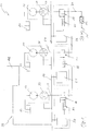
- the Fig. 1 shows a schematic representation of a pump system 10, wherein the pump system 10, a spray gun 11, a mixer 12 and pumps 13, 14 and 15 for conveying component material and respectively associated metering valves 16, 17 and 18 for metering the component material and liquid reservoirs 19, 20 and 21st to Storage of the component material includes.
- the pump system 10 comprises a control unit 22, which is formed from a control device 23 and control devices 24, 25 and 26.
- the metering valves 16, 17 and 18 are respectively associated with the pumps 13, 14 and 15 and connected via delivery lines 27, 28 and 29 with these.
- the conveyed component materials are subsequently collected in a delivery line 30 to the metering valves 16, 17 and 18 and fed to the mixer 12 and the spray gun 11.
- the component materials are mixed into the multi-component material.
- the electrical control devices 24, 25 and 26 are also associated with the pumps 13, 14 and 15 and thus also the metering valves 16, 17 and 18 respectively.
- the control devices 24, 25 and 26 control an actuator 31, 32 and 33 of the metering valves 16, 17 and 18 for opening, closing or adjusting the metering valves 16, 17 and 18 such that a control of these takes place.
- the control devices 24, 25 and 26 are controlled by the control device 23 as a master controller in the manner of cascade control.
- the control unit 22 comprises a data bus 34 to which the control device 23, the control devices 24, 25 and 26 as well as sensors 35, 36 and 37 for measuring a volume flow are connected here.
- the sensors 35, 36 and 37 may be flow rate sensors or path measuring sensors on the pumps 13, 14 and 15, respectively.
- an actual volume flow of component material of the respective pump 13, 14 or 15 is measured and transmitted to the control device 23 via the data bus 34.
- the control device 23 then provides the control devices 24, 25 and 26 via the data bus 34 each set volume flows for the component material according to the desired mixing ratio of the component material.
- the control devices 24, 25 and 26 in turn control the respective actuators 31, 32 and 33, the metering valves 16, 17 and 18, respectively, such that the respective actual volume flow is approximated to the desired volume flow.
- the metering valves 16, 17 and 18 can thereby be controlled completely independently of each other discontinuously or continuously or adjusted or clocked.
- the control device 23 and at least the respective control devices 24, 25 and 26 are each arranged in a separate housing, not shown here, which is designed to be explosion-proof.
- the Fig. 2 shows a valve assembly 38 of a pump system not shown here, wherein the valve assembly 38 metering valves 39, 40 and 41, each with associated control devices 42, 43 and 44, respectively.
- the control devices 42, 43 and 44 are arranged directly on the metering valves 39, 40 and 41, similar and formed interconnected. Further, the control devices 42, 43 and 44 are connected to a data bus 45 which connects the control devices 42, 43 and 44 with a control device, not shown here and spaced apart. Also, the control devices 42, 43 and 44 are connected to a compressed air line 46 for actuating the metering valves 39, 40 and 41 and each have an encapsulated, explosion-proof own housing 47.
- Various component materials 48, 49 and 50 are supplied to the metering valves 39, 40 and 41 in delivery lines 51, 52 and 53, respectively, and metered into a delivery line 54 upstream of a mixer, not shown here.
Landscapes
- Engineering & Computer Science (AREA)
- Mechanical Engineering (AREA)
- General Engineering & Computer Science (AREA)
- Chemical & Material Sciences (AREA)
- Chemical Kinetics & Catalysis (AREA)
- Physics & Mathematics (AREA)
- General Physics & Mathematics (AREA)
- Automation & Control Theory (AREA)
- Nozzles (AREA)
- Accessories For Mixers (AREA)
Applications Claiming Priority (1)
| Application Number | Priority Date | Filing Date | Title |
|---|---|---|---|
| DE102017216812.9A DE102017216812A1 (de) | 2017-09-22 | 2017-09-22 | Verfahren zur Steuerung eines Pumpensystems sowie Pumpensystem |
Publications (2)
| Publication Number | Publication Date |
|---|---|
| EP3460242A1 true EP3460242A1 (fr) | 2019-03-27 |
| EP3460242B1 EP3460242B1 (fr) | 2020-12-16 |
Family
ID=63517709
Family Applications (1)
| Application Number | Title | Priority Date | Filing Date |
|---|---|---|---|
| EP18192634.6A Active EP3460242B1 (fr) | 2017-09-22 | 2018-09-05 | Procédé de commande d'un système de pompe ainsi que système de pompe |
Country Status (4)
| Country | Link |
|---|---|
| US (1) | US10821461B2 (fr) |
| EP (1) | EP3460242B1 (fr) |
| DE (1) | DE102017216812A1 (fr) |
| ES (1) | ES2859735T3 (fr) |
Families Citing this family (8)
| Publication number | Priority date | Publication date | Assignee | Title |
|---|---|---|---|---|
| EP3986602A4 (fr) * | 2019-06-19 | 2023-08-02 | Merck Sharp & Dohme LLC | Système de confinement permettant le mélange de poudres sèches et de solvants pendant la production ou le traitement de médicaments |
| WO2021059031A1 (fr) * | 2019-09-26 | 2021-04-01 | Chevron U.S.A. Inc. | Tamis moléculaire ssz-114, sa synthèse et son utilisation |
| CN114643011B (zh) * | 2022-05-23 | 2022-09-23 | 杭州市红十字会医院 | 中药配方精油自动调配装置及控制系统 |
| US20230381725A1 (en) | 2022-05-31 | 2023-11-30 | Exel Industries | Mixing plant with intermediate purge and associated control method |
| FR3135907B1 (fr) | 2022-05-31 | 2025-06-20 | Exel Ind | Installation de mélange à purge intermédiaire et procédé de commande associé |
| FR3138326A1 (fr) | 2022-08-01 | 2024-02-02 | Exel Industries | Installation de mélange à purge intermédiaire et procédé de commande associé |
| FR3151672A1 (fr) * | 2023-07-24 | 2025-01-31 | Exel Industries | Procédé de dosage à alimentation alternative, et dispositifs associés |
| FR3151512A1 (fr) * | 2023-07-24 | 2025-01-31 | Exel Industries | Procédé de rinçage d’un dispositif d’application de produit de revêtement, et dispositif associé |
Citations (4)
| Publication number | Priority date | Publication date | Assignee | Title |
|---|---|---|---|---|
| US3251508A (en) * | 1963-12-27 | 1966-05-17 | Standard Oil Co | Asphalt blending system |
| US3869067A (en) * | 1972-06-26 | 1975-03-04 | Du Pont | Apparatus for gradient elution |
| US20040141409A1 (en) * | 2002-08-21 | 2004-07-22 | Hartmut Breithaupt | Apparatus and process for mixing two fluids |
| DE102012010544A1 (de) | 2012-05-29 | 2013-12-05 | J. Wagner Ag | Verfahren und Vorrichtung zum Mischen wenigstens zweier flüssiger Komponenten |
Family Cites Families (5)
| Publication number | Priority date | Publication date | Assignee | Title |
|---|---|---|---|---|
| DE19543548C2 (de) * | 1995-11-22 | 1999-09-02 | Fraunhofer Ges Forschung | System und Verfahren zur Bereitstellung und Wechsel der Materialien zum Spritzlackieren |
| DE102004038017B4 (de) * | 2004-08-04 | 2012-07-12 | Wolfgang Schmidt | Verfahren und Anlage zum zeitlich nacheinander erfolgenden Austrag unterschiedlicher Beschichtungsmaterialien |
| FR2928466B1 (fr) * | 2008-03-10 | 2010-12-17 | Exel Ind | "procede de commande d'un systeme de dosage et de melange d'un produit a plusieurs composants, ainsi que ce systeme de dosage et de melange" |
| DE102014209159A1 (de) * | 2014-05-14 | 2015-11-19 | Wiwa Wilhelm Wagner Gmbh & Co Kg | Verfahren zur Steuerung eines Pumpensystems sowie Pumpensystem |
| DE112015003583A5 (de) * | 2014-08-03 | 2018-03-15 | ATN Hölzel GmbH | Verfahren und vorrichtung zur herstellung eines zwei- oder mehrkomponentigen schaumes zum ausschäumen von hohlräumen oder von formgebenden einheiten oder körpern |
-
2017
- 2017-09-22 DE DE102017216812.9A patent/DE102017216812A1/de not_active Withdrawn
-
2018
- 2018-09-05 ES ES18192634T patent/ES2859735T3/es active Active
- 2018-09-05 EP EP18192634.6A patent/EP3460242B1/fr active Active
- 2018-09-20 US US16/136,737 patent/US10821461B2/en active Active
Patent Citations (4)
| Publication number | Priority date | Publication date | Assignee | Title |
|---|---|---|---|---|
| US3251508A (en) * | 1963-12-27 | 1966-05-17 | Standard Oil Co | Asphalt blending system |
| US3869067A (en) * | 1972-06-26 | 1975-03-04 | Du Pont | Apparatus for gradient elution |
| US20040141409A1 (en) * | 2002-08-21 | 2004-07-22 | Hartmut Breithaupt | Apparatus and process for mixing two fluids |
| DE102012010544A1 (de) | 2012-05-29 | 2013-12-05 | J. Wagner Ag | Verfahren und Vorrichtung zum Mischen wenigstens zweier flüssiger Komponenten |
Also Published As
| Publication number | Publication date |
|---|---|
| ES2859735T3 (es) | 2021-10-04 |
| EP3460242B1 (fr) | 2020-12-16 |
| DE102017216812A1 (de) | 2019-03-28 |
| US10821461B2 (en) | 2020-11-03 |
| US20190091713A1 (en) | 2019-03-28 |
Similar Documents
| Publication | Publication Date | Title |
|---|---|---|
| EP3460242B1 (fr) | Procédé de commande d'un système de pompe ainsi que système de pompe | |
| EP2185293B1 (fr) | Système d'application | |
| EP2853312B1 (fr) | Dosage ICC | |
| DE69502216T2 (de) | Zweikomponenten Abgabesystem | |
| EP2855002B1 (fr) | Procédé et dispositif pour mélanger au moins deux composants liquides | |
| DE9218528U1 (de) | Vorrichtung zum Aufbringen einer pastösen Masse | |
| DE19738141C2 (de) | Steuersystem einer Beschichtungsanlage mit einer LON-Busstruktur | |
| EP2036618A1 (fr) | Système de dosage pour une installation de revêtement | |
| DE2819302C3 (de) | Lackmengen-Steuersystem | |
| EP0958040A1 (fr) | Procede pour le transport de materiaux et dispositif pour la mise en oeuvre de ce procede | |
| DE112016005625T5 (de) | Vorrichtung zum Spritzgießen von Kunststoffmaterialien | |
| DE10012405A1 (de) | Einrichtung zur Steuerung eines hydraulischen Aktuators | |
| EP0810917B1 (fr) | Dispositif pour distribuer des materiaux coulants composes d'au moins deux constituants mutuellement reactifs, notamment des resines de coulees | |
| EP0644025B1 (fr) | Procédé pour mélanger des composants et dispositif de mise en oeuvre du procédé | |
| DE102010055019A1 (de) | Vorrichtung zum intermittierenden Auftragen eines flüssigen bis pastösen Mediums auf eine Auftragfläche | |
| DE102021123434A1 (de) | Dosiereinrichtung und Verfahren zum dosierten Ausgeben einer viskosen Wärmeleitmasse | |
| EP3143280B1 (fr) | Procédé de fonctionnement d'un système de pompe et un système de pompe | |
| DE19848640C2 (de) | Verfahren und Vorrichtung zum Dosieren und Mischen unterschiedlicher Komponenten | |
| EP1903530B1 (fr) | Agencement doté d'un appareil sous vide et son procédé de fonctionnement | |
| DE102015121535A1 (de) | Vorrichtung und Verfahren zum Mischen | |
| EP1115499B1 (fr) | Dispositif d'application de revetement en poudre | |
| DE102010047448A1 (de) | Bedarfsgerechtes Steuerverfahren für eine Beschichtungsmittelpumpe und entsprechende Pumpensteuerung | |
| EP3143279B1 (fr) | Procédé de fonctionnement d'un système de pompe et un système de pompe | |
| EP3283230B1 (fr) | Dispositif d'application de fluides | |
| EP0408051A1 (fr) | Méthode et dispositif pour le transport de substances fluides ou pâteuses |
Legal Events
| Date | Code | Title | Description |
|---|---|---|---|
| PUAI | Public reference made under article 153(3) epc to a published international application that has entered the european phase |
Free format text: ORIGINAL CODE: 0009012 |
|
| STAA | Information on the status of an ep patent application or granted ep patent |
Free format text: STATUS: THE APPLICATION HAS BEEN PUBLISHED |
|
| AK | Designated contracting states |
Kind code of ref document: A1 Designated state(s): AL AT BE BG CH CY CZ DE DK EE ES FI FR GB GR HR HU IE IS IT LI LT LU LV MC MK MT NL NO PL PT RO RS SE SI SK SM TR |
|
| AX | Request for extension of the european patent |
Extension state: BA ME |
|
| STAA | Information on the status of an ep patent application or granted ep patent |
Free format text: STATUS: REQUEST FOR EXAMINATION WAS MADE |
|
| 17P | Request for examination filed |
Effective date: 20190902 |
|
| RBV | Designated contracting states (corrected) |
Designated state(s): AL AT BE BG CH CY CZ DE DK EE ES FI FR GB GR HR HU IE IS IT LI LT LU LV MC MK MT NL NO PL PT RO RS SE SI SK SM TR |
|
| GRAP | Despatch of communication of intention to grant a patent |
Free format text: ORIGINAL CODE: EPIDOSNIGR1 |
|
| STAA | Information on the status of an ep patent application or granted ep patent |
Free format text: STATUS: GRANT OF PATENT IS INTENDED |
|
| INTG | Intention to grant announced |
Effective date: 20200716 |
|
| GRAS | Grant fee paid |
Free format text: ORIGINAL CODE: EPIDOSNIGR3 |
|
| GRAA | (expected) grant |
Free format text: ORIGINAL CODE: 0009210 |
|
| STAA | Information on the status of an ep patent application or granted ep patent |
Free format text: STATUS: THE PATENT HAS BEEN GRANTED |
|
| RAP1 | Party data changed (applicant data changed or rights of an application transferred) |
Owner name: WIWA WILHELM WAGNER GMBH & CO. KG |
|
| AK | Designated contracting states |
Kind code of ref document: B1 Designated state(s): AL AT BE BG CH CY CZ DE DK EE ES FI FR GB GR HR HU IE IS IT LI LT LU LV MC MK MT NL NO PL PT RO RS SE SI SK SM TR |
|
| REG | Reference to a national code |
Ref country code: GB Ref legal event code: FG4D Free format text: NOT ENGLISH |
|
| REG | Reference to a national code |
Ref country code: IE Ref legal event code: FG4D Free format text: LANGUAGE OF EP DOCUMENT: GERMAN |
|
| REG | Reference to a national code |
Ref country code: DE Ref legal event code: R096 Ref document number: 502018003308 Country of ref document: DE |
|
| REG | Reference to a national code |
Ref country code: AT Ref legal event code: REF Ref document number: 1345843 Country of ref document: AT Kind code of ref document: T Effective date: 20210115 |
|
| REG | Reference to a national code |
Ref country code: CH Ref legal event code: NV Representative=s name: PATENT- UND RECHTSANWAELTE BEHRMANN WAGNER PAR, CH Ref country code: CH Ref legal event code: NV Representative=s name: BODENSEEPATENT PATENTANWAELTE BEHRMANN WAGNER , CH |
|
| PG25 | Lapsed in a contracting state [announced via postgrant information from national office to epo] |
Ref country code: RS Free format text: LAPSE BECAUSE OF FAILURE TO SUBMIT A TRANSLATION OF THE DESCRIPTION OR TO PAY THE FEE WITHIN THE PRESCRIBED TIME-LIMIT Effective date: 20201216 Ref country code: FI Free format text: LAPSE BECAUSE OF FAILURE TO SUBMIT A TRANSLATION OF THE DESCRIPTION OR TO PAY THE FEE WITHIN THE PRESCRIBED TIME-LIMIT Effective date: 20201216 Ref country code: GR Free format text: LAPSE BECAUSE OF FAILURE TO SUBMIT A TRANSLATION OF THE DESCRIPTION OR TO PAY THE FEE WITHIN THE PRESCRIBED TIME-LIMIT Effective date: 20210317 Ref country code: NO Free format text: LAPSE BECAUSE OF FAILURE TO SUBMIT A TRANSLATION OF THE DESCRIPTION OR TO PAY THE FEE WITHIN THE PRESCRIBED TIME-LIMIT Effective date: 20210316 |
|
| REG | Reference to a national code |
Ref country code: NL Ref legal event code: MP Effective date: 20201216 |
|
| PG25 | Lapsed in a contracting state [announced via postgrant information from national office to epo] |
Ref country code: BG Free format text: LAPSE BECAUSE OF FAILURE TO SUBMIT A TRANSLATION OF THE DESCRIPTION OR TO PAY THE FEE WITHIN THE PRESCRIBED TIME-LIMIT Effective date: 20210316 Ref country code: SE Free format text: LAPSE BECAUSE OF FAILURE TO SUBMIT A TRANSLATION OF THE DESCRIPTION OR TO PAY THE FEE WITHIN THE PRESCRIBED TIME-LIMIT Effective date: 20201216 Ref country code: LV Free format text: LAPSE BECAUSE OF FAILURE TO SUBMIT A TRANSLATION OF THE DESCRIPTION OR TO PAY THE FEE WITHIN THE PRESCRIBED TIME-LIMIT Effective date: 20201216 |
|
| PG25 | Lapsed in a contracting state [announced via postgrant information from national office to epo] |
Ref country code: NL Free format text: LAPSE BECAUSE OF FAILURE TO SUBMIT A TRANSLATION OF THE DESCRIPTION OR TO PAY THE FEE WITHIN THE PRESCRIBED TIME-LIMIT Effective date: 20201216 Ref country code: HR Free format text: LAPSE BECAUSE OF FAILURE TO SUBMIT A TRANSLATION OF THE DESCRIPTION OR TO PAY THE FEE WITHIN THE PRESCRIBED TIME-LIMIT Effective date: 20201216 |
|
| REG | Reference to a national code |
Ref country code: LT Ref legal event code: MG9D |
|
| PG25 | Lapsed in a contracting state [announced via postgrant information from national office to epo] |
Ref country code: LT Free format text: LAPSE BECAUSE OF FAILURE TO SUBMIT A TRANSLATION OF THE DESCRIPTION OR TO PAY THE FEE WITHIN THE PRESCRIBED TIME-LIMIT Effective date: 20201216 Ref country code: RO Free format text: LAPSE BECAUSE OF FAILURE TO SUBMIT A TRANSLATION OF THE DESCRIPTION OR TO PAY THE FEE WITHIN THE PRESCRIBED TIME-LIMIT Effective date: 20201216 Ref country code: SK Free format text: LAPSE BECAUSE OF FAILURE TO SUBMIT A TRANSLATION OF THE DESCRIPTION OR TO PAY THE FEE WITHIN THE PRESCRIBED TIME-LIMIT Effective date: 20201216 Ref country code: PT Free format text: LAPSE BECAUSE OF FAILURE TO SUBMIT A TRANSLATION OF THE DESCRIPTION OR TO PAY THE FEE WITHIN THE PRESCRIBED TIME-LIMIT Effective date: 20210416 Ref country code: SM Free format text: LAPSE BECAUSE OF FAILURE TO SUBMIT A TRANSLATION OF THE DESCRIPTION OR TO PAY THE FEE WITHIN THE PRESCRIBED TIME-LIMIT Effective date: 20201216 Ref country code: CZ Free format text: LAPSE BECAUSE OF FAILURE TO SUBMIT A TRANSLATION OF THE DESCRIPTION OR TO PAY THE FEE WITHIN THE PRESCRIBED TIME-LIMIT Effective date: 20201216 Ref country code: EE Free format text: LAPSE BECAUSE OF FAILURE TO SUBMIT A TRANSLATION OF THE DESCRIPTION OR TO PAY THE FEE WITHIN THE PRESCRIBED TIME-LIMIT Effective date: 20201216 |
|
| PG25 | Lapsed in a contracting state [announced via postgrant information from national office to epo] |
Ref country code: PL Free format text: LAPSE BECAUSE OF FAILURE TO SUBMIT A TRANSLATION OF THE DESCRIPTION OR TO PAY THE FEE WITHIN THE PRESCRIBED TIME-LIMIT Effective date: 20201216 |
|
| REG | Reference to a national code |
Ref country code: DE Ref legal event code: R097 Ref document number: 502018003308 Country of ref document: DE |
|
| PG25 | Lapsed in a contracting state [announced via postgrant information from national office to epo] |
Ref country code: IS Free format text: LAPSE BECAUSE OF FAILURE TO SUBMIT A TRANSLATION OF THE DESCRIPTION OR TO PAY THE FEE WITHIN THE PRESCRIBED TIME-LIMIT Effective date: 20210416 |
|
| REG | Reference to a national code |
Ref country code: ES Ref legal event code: FG2A Ref document number: 2859735 Country of ref document: ES Kind code of ref document: T3 Effective date: 20211004 |
|
| PLBE | No opposition filed within time limit |
Free format text: ORIGINAL CODE: 0009261 |
|
| STAA | Information on the status of an ep patent application or granted ep patent |
Free format text: STATUS: NO OPPOSITION FILED WITHIN TIME LIMIT |
|
| PG25 | Lapsed in a contracting state [announced via postgrant information from national office to epo] |
Ref country code: AL Free format text: LAPSE BECAUSE OF FAILURE TO SUBMIT A TRANSLATION OF THE DESCRIPTION OR TO PAY THE FEE WITHIN THE PRESCRIBED TIME-LIMIT Effective date: 20201216 |
|
| 26N | No opposition filed |
Effective date: 20210917 |
|
| PG25 | Lapsed in a contracting state [announced via postgrant information from national office to epo] |
Ref country code: DK Free format text: LAPSE BECAUSE OF FAILURE TO SUBMIT A TRANSLATION OF THE DESCRIPTION OR TO PAY THE FEE WITHIN THE PRESCRIBED TIME-LIMIT Effective date: 20201216 |
|
| PG25 | Lapsed in a contracting state [announced via postgrant information from national office to epo] |
Ref country code: SI Free format text: LAPSE BECAUSE OF FAILURE TO SUBMIT A TRANSLATION OF THE DESCRIPTION OR TO PAY THE FEE WITHIN THE PRESCRIBED TIME-LIMIT Effective date: 20201216 |
|
| PG25 | Lapsed in a contracting state [announced via postgrant information from national office to epo] |
Ref country code: IS Free format text: LAPSE BECAUSE OF FAILURE TO SUBMIT A TRANSLATION OF THE DESCRIPTION OR TO PAY THE FEE WITHIN THE PRESCRIBED TIME-LIMIT Effective date: 20210416 Ref country code: MC Free format text: LAPSE BECAUSE OF FAILURE TO SUBMIT A TRANSLATION OF THE DESCRIPTION OR TO PAY THE FEE WITHIN THE PRESCRIBED TIME-LIMIT Effective date: 20201216 |
|
| PG25 | Lapsed in a contracting state [announced via postgrant information from national office to epo] |
Ref country code: LU Free format text: LAPSE BECAUSE OF NON-PAYMENT OF DUE FEES Effective date: 20210905 Ref country code: IE Free format text: LAPSE BECAUSE OF NON-PAYMENT OF DUE FEES Effective date: 20210905 |
|
| P01 | Opt-out of the competence of the unified patent court (upc) registered |
Effective date: 20230524 |
|
| PG25 | Lapsed in a contracting state [announced via postgrant information from national office to epo] |
Ref country code: CY Free format text: LAPSE BECAUSE OF FAILURE TO SUBMIT A TRANSLATION OF THE DESCRIPTION OR TO PAY THE FEE WITHIN THE PRESCRIBED TIME-LIMIT Effective date: 20201216 |
|
| PG25 | Lapsed in a contracting state [announced via postgrant information from national office to epo] |
Ref country code: HU Free format text: LAPSE BECAUSE OF FAILURE TO SUBMIT A TRANSLATION OF THE DESCRIPTION OR TO PAY THE FEE WITHIN THE PRESCRIBED TIME-LIMIT; INVALID AB INITIO Effective date: 20180905 |
|
| PG25 | Lapsed in a contracting state [announced via postgrant information from national office to epo] |
Ref country code: MK Free format text: LAPSE BECAUSE OF FAILURE TO SUBMIT A TRANSLATION OF THE DESCRIPTION OR TO PAY THE FEE WITHIN THE PRESCRIBED TIME-LIMIT Effective date: 20201216 |
|
| PG25 | Lapsed in a contracting state [announced via postgrant information from national office to epo] |
Ref country code: TR Free format text: LAPSE BECAUSE OF FAILURE TO SUBMIT A TRANSLATION OF THE DESCRIPTION OR TO PAY THE FEE WITHIN THE PRESCRIBED TIME-LIMIT Effective date: 20201216 |
|
| PG25 | Lapsed in a contracting state [announced via postgrant information from national office to epo] |
Ref country code: MT Free format text: LAPSE BECAUSE OF FAILURE TO SUBMIT A TRANSLATION OF THE DESCRIPTION OR TO PAY THE FEE WITHIN THE PRESCRIBED TIME-LIMIT Effective date: 20201216 |
|
| REG | Reference to a national code |
Ref country code: CH Ref legal event code: U11 Free format text: ST27 STATUS EVENT CODE: U-0-0-U10-U11 (AS PROVIDED BY THE NATIONAL OFFICE) Effective date: 20251001 |
|
| PGFP | Annual fee paid to national office [announced via postgrant information from national office to epo] |
Ref country code: BE Payment date: 20250919 Year of fee payment: 8 Ref country code: GB Payment date: 20250923 Year of fee payment: 8 |
|
| PGFP | Annual fee paid to national office [announced via postgrant information from national office to epo] |
Ref country code: FR Payment date: 20250924 Year of fee payment: 8 Ref country code: AT Payment date: 20250918 Year of fee payment: 8 |
|
| PGFP | Annual fee paid to national office [announced via postgrant information from national office to epo] |
Ref country code: DE Payment date: 20251120 Year of fee payment: 8 |
|
| PGFP | Annual fee paid to national office [announced via postgrant information from national office to epo] |
Ref country code: IT Payment date: 20250930 Year of fee payment: 8 |
|
| PGFP | Annual fee paid to national office [announced via postgrant information from national office to epo] |
Ref country code: CH Payment date: 20251001 Year of fee payment: 8 |
|
| PGFP | Annual fee paid to national office [announced via postgrant information from national office to epo] |
Ref country code: ES Payment date: 20251020 Year of fee payment: 8 |