EP3460281A1 - Accouplement à limitation de couple - Google Patents
Accouplement à limitation de couple Download PDFInfo
- Publication number
- EP3460281A1 EP3460281A1 EP17192041.6A EP17192041A EP3460281A1 EP 3460281 A1 EP3460281 A1 EP 3460281A1 EP 17192041 A EP17192041 A EP 17192041A EP 3460281 A1 EP3460281 A1 EP 3460281A1
- Authority
- EP
- European Patent Office
- Prior art keywords
- blocking
- torque limiting
- locking
- release
- clutch hub
- Prior art date
- Legal status (The legal status is an assumption and is not a legal conclusion. Google has not performed a legal analysis and makes no representation as to the accuracy of the status listed.)
- Granted
Links
Images



Classifications
-
- F—MECHANICAL ENGINEERING; LIGHTING; HEATING; WEAPONS; BLASTING
- F16—ENGINEERING ELEMENTS AND UNITS; GENERAL MEASURES FOR PRODUCING AND MAINTAINING EFFECTIVE FUNCTIONING OF MACHINES OR INSTALLATIONS; THERMAL INSULATION IN GENERAL
- F16D—COUPLINGS FOR TRANSMITTING ROTATION; CLUTCHES; BRAKES
- F16D43/00—Automatic clutches
- F16D43/02—Automatic clutches actuated entirely mechanically
- F16D43/20—Automatic clutches actuated entirely mechanically controlled by torque, e.g. overload-release clutches, slip-clutches with means by which torque varies the clutching pressure
- F16D43/202—Automatic clutches actuated entirely mechanically controlled by torque, e.g. overload-release clutches, slip-clutches with means by which torque varies the clutching pressure of the ratchet type
- F16D43/204—Automatic clutches actuated entirely mechanically controlled by torque, e.g. overload-release clutches, slip-clutches with means by which torque varies the clutching pressure of the ratchet type with intermediate balls or rollers
- F16D43/206—Automatic clutches actuated entirely mechanically controlled by torque, e.g. overload-release clutches, slip-clutches with means by which torque varies the clutching pressure of the ratchet type with intermediate balls or rollers moving axially between engagement and disengagement
-
- F—MECHANICAL ENGINEERING; LIGHTING; HEATING; WEAPONS; BLASTING
- F16—ENGINEERING ELEMENTS AND UNITS; GENERAL MEASURES FOR PRODUCING AND MAINTAINING EFFECTIVE FUNCTIONING OF MACHINES OR INSTALLATIONS; THERMAL INSULATION IN GENERAL
- F16D—COUPLINGS FOR TRANSMITTING ROTATION; CLUTCHES; BRAKES
- F16D7/00—Slip couplings, e.g. slipping on overload, for absorbing shock
- F16D7/04—Slip couplings, e.g. slipping on overload, for absorbing shock of the ratchet type
- F16D7/06—Slip couplings, e.g. slipping on overload, for absorbing shock of the ratchet type with intermediate balls or rollers
- F16D7/08—Slip couplings, e.g. slipping on overload, for absorbing shock of the ratchet type with intermediate balls or rollers moving axially between engagement and disengagement
Definitions
- the invention relates to a torque limiting clutch, which is arranged rotatably about a longitudinal axis.
- the torque limiting clutch has a clutch hub having circumferentially distributed apertures.
- Driver body are held parallel to the longitudinal axis adjustable in the openings of the clutch hub.
- a coupling sleeve has first recesses corresponding to the apertures.
- a shift dial is rotatably disposed between a coupling position and a disengaging position relative to the clutch hub.
- the indexing disc has corresponding openings to the second recesses, in which engage the driver body in the disengaging position, wherein when a predetermined limit torque is exceeded by a rolling movement of the driver body, the indexing disk from the coupling position in the disengaged position can be transferred.
- First spring means act on the indexing disk axially, wherein in torque transmission between the coupling hub and the coupling sleeve, the driver bodies are acted upon by the indexing disk against the coupling sleeve and held in the Einkuppelposition for torque transmission in the first recesses.
- Second spring means act on the indexing disc in the circumferential direction to take the Einkuppelposition.
- the torque limiting clutch further comprises at least one locking element which is adjustable between a locking position and a release position and is subjected to force in the direction of the blocking position, wherein the blocking element in the disengaged position of the indexing disk is in the locked position can be transferred, in which the blocking element in the circumferential direction against the clutch hub and is supported against the switching disc and locks the switching disc against rotation relative to the clutch hub.
- Such a torque limiting clutch is from the DE 28 53 293 C2 known.
- the blocking element is used to hold the indexing disk after its transfer to the disengaging position in order to avoid that the indexing disk is automatically transferred to the coupling position.
- the one coupling part may be formed as a clutch hub and circumferentially distributed apertures, in which acting as a driver body rolling elements are held, which engage in the torque transmission in recesses of the other coupling part.
- the overload clutch further comprises a force acting in the torque transmission position by circumferentially acting springs angularly offset from the other coupling part held switching ring.
- the switching ring is provided with corresponding to the recesses of the other coupling part recesses. The driver body based on torque transmission through the switching ring against the force of a held between two stops axial spring.
- the switching ring is rotatable when exceeding a predetermined nominal torque by a rolling movement of the driver body from the recesses of the other coupling member against the force of the spring acting in the circumferential direction such that the recesses of the switching ring are adjustable to the openings in a corresponding angular position.
- At least one locking pin is guided axially limited movable in the coupling part designed as a coupling part.
- the locking pin is held up by the force of a spring on the side facing the switching ring from the clutch hub.
- On the switching ring is one in the torque transmission position with the recess pin aligned recess provided, in which the locking pin dips and so keeps the switching ring in the torque transmission position until the rated torque is exceeded.
- Object of the present invention is to provide a torque limiting coupling, which ensures on the one hand that a reconnection is possible only by an active actuation of a person. On the other hand, it should be ensured that when torsional vibrations occur, unintentional disconnection of the torque limiting clutch is avoided if a predetermined limit torque has not yet been reached or has not yet been exceeded.
- the object is achieved by a torque limiting clutch, which is arranged rotatably about a longitudinal axis.
- the torque limiting clutch has a clutch hub having circumferentially distributed apertures.
- Driver body are held parallel to the longitudinal axis adjustable in the openings of the clutch hub.
- a coupling sleeve has first recesses corresponding to the apertures.
- a shift dial is rotatably disposed between a coupling position and a disengaging position relative to the clutch hub.
- the indexing disc has corresponding openings to the second recesses, in which engage the driver body in the disengaging position, wherein when a predetermined limit torque is exceeded by a rolling movement of the driver body, the indexing disk from the coupling position in the disengaged position can be transferred.
- First spring means act on the switching disk axially, wherein the torque transmission between the clutch hub and the coupling sleeve, the driver body are acted upon by the switching disk against the coupling sleeve and are held in the Einkuppelposition for torque transmission in the first recesses.
- Second spring means act on the indexing disc in the circumferential direction to take the Einkuppelposition.
- the torque limiting clutch further comprises at least one locking element which is adjustable between a locking position and a release position and is subjected to force in the direction of the locking position, wherein the blocking element in the disengaged position of the indexing disk in the Locking position can be transferred, in which the blocking element is supported in the circumferential direction against the clutch hub and against the switching disk and the switching disc locks against rotation relative to the clutch hub.
- the at least one blocking element is additionally in the engaged position of the indexing disk into the locked position can be transferred, in which the blocking element is supported in the circumferential direction against the clutch hub and against the switching disk and locks the switching disk against rotation relative to the clutch hub.
- the at least one blocking element therefore has two functions.
- the blocking element in the disengaging position of the indexing disk can be transferred into the blocking position, in which the blocking element is supported in the circumferential direction against the coupling hub and against the indexing disk and blocks the indexing disk against rotation relative to the coupling hub.
- the blocking element thus acts as a switch-on lock, which prevents the torque limiting clutch from automatically switching on again when the torque falls below the limit torque again after the limit torque has been exceeded.
- the at least one blocking element can additionally be transferred into the engagement position of the indexing disk into the blocking position, in which the blocking element is supported in the circumferential direction against the coupling hub and against the indexing disk and blocks the indexing disk against rotation relative to the coupling hub.
- the blocking element thus acts as a torsional vibration limiter, is prevented by the fact that the torque limiting clutch shuts off when torsional vibrations occur, without the limit torque was exceeded.
- the insensitivity to torsional vibrations when using the torque limiting clutch in drive trains arranged between a tractor and an agricultural implement has a particularly advantageous effect, since the articulated shafts used here are subjected to strong bends due to the small available free space.
- mainly universal joint shafts with two universal joints are used. If set during the bending of the propeller shaft different flexion angles in the universal joints, there is a non-uniform rotational motion transmission and thus torsional vibrations. These can be absorbed by the torque limiting clutch according to the invention without unwanted shutdown.
- torque limiting clutch is not limited to the described application, but is recommended wherever possible in overload to be protected drive trains torsional vibrations.
- this has a release element which is adjustable between a neutral position and a release position, wherein by adjusting the release element in the release position, the at least one blocking element is transferred from the release element in the release position.
- the at least one blocking element can be transferred from the blocking position into the release position, in particular when the torque limiting clutch is switched off, in order to switch on the torque limiting clutch again after the occurrence of an overload and switching off the torque limiting clutch. This ensures that a restart of the torque limiting clutch is possible only by active action of an operator.
- the torque limiting clutch can not switch on automatically unintentionally and uncontrollably.
- a plurality of locking elements which also distributed over the circumference, in particular evenly distributed, can be arranged.
- the force for supporting the clutch hub and the indexing disk is distributed to a plurality of locking elements.
- the individual locking elements can be designed correspondingly smaller than with only one locking element.
- the at least one blocking element may be adjustably received in an embodiment in a guide recess of the clutch hub.
- a guide recess is provided correspondingly for each individual blocking element.
- the blocking element may in this case be displaceable in the guide recess, in particular axially displaceable parallel to the longitudinal axis.
- each blocking element In the blocking position, the at least one blocking element can engage in a locking recess of the indexing disk.
- each blocking element may be provided with a first locking recess, into which the respective blocking element engages in the engagement position of the switching disk.
- each locking element may be provided a second locking recess into which engages the respective locking element in the disengaging position of the switching disc.
- the at least one blocking element can sit in one embodiment of the torque limiting coupling with circumferential clearance in the first locking recess and / or in the second locking recess.
- the width of the first locking recess and / or in the second locking recess in the circumferential direction can be greater than the width of the at least one locking element in the circumferential direction.
- the circumferential clearance is used so that the switching disc can rotate better when exceeding a limit torque already when rolling out the driver body from the first recesses of the coupling sleeve.
- the release element is a cover housing the torque limiting clutch.
- the cover housing serves to cover at least the switching disk, the at least one locking element and at least partially cover the clutch hub and the coupling sleeve to the outside or.
- the cover can be designed cup-shaped.
- the release element may be arranged axially displaceable or rotatable relative to the clutch hub.
- the release element has a contact surface with which the release element is transferred from the locking position to the release position when transferring from the neutral position into the release position.
- the contact surface can be formed, for example, as a cone surface with an axially displaceable release element.
- the at least one blocking element has a contact surface against which the contact surface of the release element for transferring the at least one blocking element from the blocking position to the release position in abutment.
- the contact surface can be designed as a surface extending obliquely to the longitudinal axis.
- the at least one blocking element is part of a locking ring, which is adjustable between the locking position and the release position.
- a plurality of locking elements may be part of a single component in order to simplify assembly, among other things.
- the blocking ring can have a contact surface which forms the contact surface of the at least one blocking element.
- a contact surface which forms the contact surface of all blocking elements.
- the contact surface may, for example, be designed as a circumferential surface which forms sections of the blocking elements.
- the driver bodies are received with peripheral clearance in the second recesses of the indexing disk.
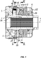
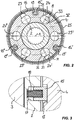
- FIGS. 1 to 4 a torque limiting clutch according to the invention is shown in a torque transmitting position. The figures will be described together below.
- the torque limiting clutch is rotatably arranged about a longitudinal axis 1 and has a clutch hub 2, a coupling sleeve 3 and a switching disk 4.
- the clutch hub 2 has circumferentially distributed openings 5, in which acting as a rolling body driving elements 6 are held in the form of balls parallel to the longitudinal axis 1 adjustable.
- the driver bodies 6 can also be designed in another form, such as in the form of rollers.
- the coupling sleeve 3 faces the Openings 5 corresponding first recesses 7 on.
- the switching disk 4 has second recesses 8 corresponding to the apertures 5.
- the switching disk 4 is about the longitudinal axis 1 relative to the clutch hub 2 between a in the FIGS. 1 to 4 shown Einkuppelposition and one in the FIGS. 5 to 8 rotatably arranged Auskuppelposition shown.
- the driver body 6 protrude in the direction of the coupling sleeve 3 out of the openings 5 and engage in the first recesses 7 a.
- the driver body 6 On the side facing away from the coupling sleeve 3, the driver body 6 also protrude from the apertures 5 and are axially supported against second grooves 9, which are arranged between the second recesses 8 of the indexing disk 4.
- the switching disc 4 may be formed without grooves, so that the driver body 6 are supported against an end face of the switching disc.
- the first recesses 7 of the coupling sleeve 3 and the second recesses 8 of the switching disc 4 are offset in the ON position with respect to their rotational position to each other.
- the switching disk 4 is axially supported via a thrust bearing 10 against a pressure ring 11, wherein the pressure ring 11 is acted upon by a first spring element in the form of a cup spring pact 12 axially in the direction of the switching disk 4 with force.
- the cup spring package 12 is axially supported against a support ring 13 on the clutch hub 2.
- the driver body 6 are held in the first recesses 7.
- the pressure ring 11 is axially supported against a shoulder 36 of the clutch hub 2.
- the plate spring package 12 may also be provided another suitable spring element or a spring arrangement, such as a helical compression spring.
- the driver body 6 When a limit torque is exceeded, the driver body 6 are pushed out of the first recesses 7 against the spring force of the plate spring package 12, wherein this is compressed by an axial movement of the switching disk 4 in the direction of the plate spring package 12.
- the driver body 6 roll in this case in the second grooves 9 of the indexing disk 4 and in first grooves 14 (FIG. FIG. 5 ) between the first recesses 7 of the coupling sleeve 3, wherein due to the Rolling movements of the driver body 6, the switching disk 4 is rotated relative to the clutch hub 2 about the longitudinal axis 1 against the force of a circumferentially acting second spring element in the form of a clamping clamp package 20.
- the coupling sleeve 3 may also be designed without running grooves, so that the driver bodies 6 are supported against an end face of the coupling sleeve 3.
- the indexing disk is turned clockwise. In principle, it can be provided that the rotation also takes place in the other direction or in both directions.
- the driver bodies 6 engage in the second recesses 8, the switching disk 4 being moved back axially in the direction of the coupling sleeve 3 due to the spring force of the first spring element in the form of the plate spring assembly 12.
- the torque transmission between the coupling sleeve 3 and the clutch hub 2 is interrupted, so that the coupling sleeve 3 rotates relative to the clutch hub 2, wherein the driver 6 roll in the first grooves 14 of the coupling sleeve 3 or unmoved with axial play in the second recesses 8 be included.
- a plurality of locking elements 15, 15 ', 15 "arranged distributed over the circumference are provided, In the exemplary embodiment shown, three locking elements 15, 15', 15" are arranged. However, it is also conceivable a different number of locking elements, such as a single blocking element.
- the blocking elements 15, 15 ', 15 are part of a blocking ring 16 and protrude radially inwards
- the blocking ring 16 is arranged around the coupling hub 2, wherein the blocking elements 15, 15', 15" are guided radially inward into guide recesses 17, 17 '.
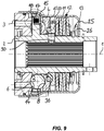
- the locking elements 15, 15 ', 15 are in these guide recesses 17, 17', 17" axially parallel to the longitudinal axis 1 between a locking position (FIG. FIGS. 1 . 3 . 5 and 7 ) and a release position ( Figures 9 and 10 ) adjustable.
- the blocking elements 15, 15 ', 15 are displaceable.
- the guide recesses 17, 17 ', 17 open in the direction of the switching disk 4, wherein the locking elements 15, 15', 15" are each acted upon by a spring 18 in the direction of the switching disk 4 with force.
- the locking elements 15, 15 ', 15 each engage in a first locking recess 19, 19', 19" of the indexing disk 4, as shown in particular in FIG. 3 can be seen.
- the switching disk 4 is held in its Einkuppelposition.
- the locking elements 15, 15 ', 15 are received with circumferential clearance in the first locking recesses 19, 19', 19", so that a limited rotational movement between the switching disc 4 and the clutch hub 2 is possible.
- the first Sperrausappels 19, 19 ', 19 “seen in the circumferential direction designed wider than the locking elements 15, 15', 15”.
- the driver body 6 are received with circumferential clearance in the second recesses 8 of the switching disk 4.
- All second recesses 8 are identical and provided for the sake of clarity with the same reference numerals.
- the second recesses 8, viewed in the circumferential direction are made wider than those sections of the driving bodies 6 which dip into the second recesses 8. As a result, a limited rotational movement between the clutch hub 2 and the switching disk 4 is made possible without the switching disk 4 is already axially displaced against the spring force of the plate spring package 12.
- the second recesses 8 are spherically formed in two arranged in the direction of rotation at the ends of the second recesses 8 end portions 31, 32 and adapted to the spherical surface of the driver 6, so that the driver body 6 in these end portions 31, 32 of the second recesses 8 to this nestle.
- the second recesses 8 are each flattened in the circumferential direction or rectilinear, so that For the driver 6 a circumferential clearance within the second recesses 8 results.
- the indexing disk 4 has an axially projecting above the pressure ring 11 first projection 21.
- the pressure ring 11 has a radially outwardly projecting second projection 22.
- the first projection 21 and the second projection 22 are aligned in the radial direction.
- the clamping clip package 20 is arranged, which is formed with two approximately radially extending legs 34, 35, wherein each of the two legs 34, 35 is supported against both projections 21, 22 in the circumferential direction.
- the pressure ring 11 is rotatably held on the clutch hub 2 via a tongue and groove connection 30.
- the indexing disk 4 When transferring the indexing disk 4 from the coupling position to the disengaging position, the indexing disk 4 is rotated relative to the coupling hub 2 and the pressure ring 11 held in a rotationally fixed manner with it. This supports one of the legs 34 in the circumferential direction against the second projection 22 of the pressure ring 11 and the other of the two legs 35 in the circumferential direction against the first projection 21 of the indexing disk 4 from.
- the clamp assembly 20 is expanded and biased in the circumferential direction, so that the switching disk 4 is acted upon to take the on position in the circumferential direction with force.
- the driver body 6 When falling below the limit torque due to the acted upon to take the switch-on switching disk 4, the driver body 6 would be pressed by the switching disk 4 in the first recesses 7 of the coupling sleeve 3. If the speed difference between the clutch hub 2 and the coupling sleeve 3 falls below a certain value, the switching disk 4 is rotated back over the first recesses 7 in the engaged position when overrunning the driver body 6. If the limit torque is then sufficiently undershot, the switching disk 4 would remain in the engaged position and the torque limiting clutch remain switched on accordingly.
- 4 second locking recesses 23, 23 ', 23 “, 24, 24', 24” are arranged in the indexing disk.
- the locking elements 15, 15 ', 15 engage in their locking position and in the disengaged position of the indexing disk 4 in second locking recesses 23, 23', 23", which in the illustration of FIG. 6
- the blocking elements 15, 15 ', 15 would engage in second locking recesses 24, 24', 24", which are in the counterclockwise direction to one of the first blocking recesses 19, 19 ', 19 " the representation of FIG. 6 each in the clockwise direction adjacent to one of the first locking recesses 19, 19 ', 19 "is arranged.
- a release element 25 is provided to release the blocking elements 15, 15 ', 15 ", that is to say for transferring the blocking elements 15, 15', 15” from the blocking position into the release position.
- the release element 25 is shown in the embodiment shown by a cover housing, which receives the plate spring assembly 12, the pressure ring 11, the switching disc 4 and partially the clutch hub 2 and partially the coupling sleeve 3.
- the release element 25 may alternatively be designed as a separate component.
- the release member 25 is slidably guided against the force of a compression spring 26 between a neutral position and a release position on the clutch hub 2. It is also conceivable another adjustability of the release element 25, such as the rotatability of the release element 25. Further, instead of a compression spring another spring element can be used.
- the release element 25 has a contact surface 27, with which the release element 25 transfers the blocking elements 15, 15 ', 15 "from the blocking position to the release position during the transfer from the neutral position to the release position and is designed conical, with the cone angle of the cone-shaped contact surface 27 in the direction opens to the locking ring 16 out. It is also conceivable another design of the contact surface 27th
- the abutment surface 27 cooperates with abutment surfaces 28 of the blocking elements 15, 15 ', 15 ", wherein the abutment surfaces 28 merge with one another in the circumferential direction on the blocking ring 16 in such a way that they form a continuous abutment surface 28.
- the abutment surface 28 is also cone-shaped and has the same Cone angle on how the cone-shaped contact surface 27. It is also conceivable another design of the contact surface 27 and contact surface 28th
- the blocking elements 15, 15 ', 15 " In the disengaged position of the indexing disk 4 and in the blocking position of the blocking elements 15, 15 ', 15 “, the blocking elements 15, 15', 15” in each case against a blocking surface 29 of the respective second locking recess 23, 23 ', 23 “, 24, 24' , 24 “pressed ( FIG. 7 ).
- the driver body 6 In this position of the switching disk 4, the driver body 6 are at least approximately in the middle of the second recesses 8 (FIG. FIG. 6 ).
- the indexing disk 4 is therefore slightly rotated within the second recesses 8 by the force of the tensioning clamping packet 20 due to the circumferential play between the entrainment bodies 6.
- the blocking elements 15, 15', 15 are aligned "in the circumferential direction with the second locking recesses 23, 23 ', 23", 24, 24', 24 "( FIG. 10 ).
- the blocking elements 15, 15 ', 15 therefore do not again engage in the second blocking recesses 23, 23', 23", 24, 24 ', 24 " Because the torque limiting clutch for actuating the release element 25 is stopped, the torque limiting clutch can now be switched on again when the drive train in which the torque limiting clutch is arranged is re-started.
Landscapes
- Engineering & Computer Science (AREA)
- General Engineering & Computer Science (AREA)
- Mechanical Engineering (AREA)
- Mechanical Operated Clutches (AREA)
Priority Applications (2)
| Application Number | Priority Date | Filing Date | Title |
|---|---|---|---|
| EP17192041.6A EP3460281B1 (fr) | 2017-09-20 | 2017-09-20 | Accouplement à limitation de couple |
| US16/133,834 US10844914B2 (en) | 2017-09-20 | 2018-09-18 | Torque limiting coupling |
Applications Claiming Priority (1)
| Application Number | Priority Date | Filing Date | Title |
|---|---|---|---|
| EP17192041.6A EP3460281B1 (fr) | 2017-09-20 | 2017-09-20 | Accouplement à limitation de couple |
Publications (2)
| Publication Number | Publication Date |
|---|---|
| EP3460281A1 true EP3460281A1 (fr) | 2019-03-27 |
| EP3460281B1 EP3460281B1 (fr) | 2019-11-06 |
Family
ID=59923294
Family Applications (1)
| Application Number | Title | Priority Date | Filing Date |
|---|---|---|---|
| EP17192041.6A Active EP3460281B1 (fr) | 2017-09-20 | 2017-09-20 | Accouplement à limitation de couple |
Country Status (2)
| Country | Link |
|---|---|
| US (1) | US10844914B2 (fr) |
| EP (1) | EP3460281B1 (fr) |
Families Citing this family (1)
| Publication number | Priority date | Publication date | Assignee | Title |
|---|---|---|---|---|
| EP4071375A1 (fr) * | 2021-04-07 | 2022-10-12 | Off-Highway Powertrain Services Germany GmbH | Dispositif de mesure permettant de déterminer un paramètre de fonctionnement d'un arbre d'articulation agricole |
Citations (4)
| Publication number | Priority date | Publication date | Assignee | Title |
|---|---|---|---|---|
| DE3151485C1 (de) | 1981-12-24 | 1983-01-27 | Jean Walterscheid Gmbh, 5204 Lohmar | UEberlastkupplung |
| DE2853293C2 (de) | 1978-12-09 | 1983-12-29 | Jean Walterscheid Gmbh, 5204 Lohmar | Überlastkupplung |
| DE19611622C1 (de) * | 1996-03-25 | 1997-07-24 | Walterscheid Gmbh Gkn | Drehmomentbegrenzungskupplung |
| DE10201988A1 (de) * | 2002-01-21 | 2003-09-18 | Walterscheid Gmbh Gkn | Drehmomentbegrenzungskupplung |
-
2017
- 2017-09-20 EP EP17192041.6A patent/EP3460281B1/fr active Active
-
2018
- 2018-09-18 US US16/133,834 patent/US10844914B2/en active Active
Patent Citations (4)
| Publication number | Priority date | Publication date | Assignee | Title |
|---|---|---|---|---|
| DE2853293C2 (de) | 1978-12-09 | 1983-12-29 | Jean Walterscheid Gmbh, 5204 Lohmar | Überlastkupplung |
| DE3151485C1 (de) | 1981-12-24 | 1983-01-27 | Jean Walterscheid Gmbh, 5204 Lohmar | UEberlastkupplung |
| DE19611622C1 (de) * | 1996-03-25 | 1997-07-24 | Walterscheid Gmbh Gkn | Drehmomentbegrenzungskupplung |
| DE10201988A1 (de) * | 2002-01-21 | 2003-09-18 | Walterscheid Gmbh Gkn | Drehmomentbegrenzungskupplung |
Also Published As
| Publication number | Publication date |
|---|---|
| EP3460281B1 (fr) | 2019-11-06 |
| US20190085915A1 (en) | 2019-03-21 |
| US10844914B2 (en) | 2020-11-24 |
Similar Documents
| Publication | Publication Date | Title |
|---|---|---|
| DE10024658C2 (de) | Synchronisiereinrichtung für ein Handschaltgetriebe | |
| DE2934164C2 (de) | Ausrückkupplung | |
| EP2475907B1 (fr) | Synchronisation pour une boîte de vitesses | |
| DE102014008287B3 (de) | Freischaltende Überlastkupplung mit gruppenweise angeordneten Übertragungskörpern | |
| EP2235391B1 (fr) | Élément amplificateur de force | |
| DE112016003113T5 (de) | Drehmomentschwankungs-Verhinderungsvorrichtung, Drehmomentwandler und Kraftübertragungsvorrichtung | |
| EP3312446B1 (fr) | Unité de synchronisation pour une boîte de vitesses ainsi que boîte de vitesses | |
| DE3819481C1 (fr) | ||
| DE102013224437A1 (de) | Drehschwingungsdämpfer | |
| DE3151485C1 (de) | UEberlastkupplung | |
| DE112012005237T5 (de) | Kupplungsaktuator | |
| EP3328683B1 (fr) | Dispositif de réglage de siège avec verrouillage supplémentaire | |
| EP2045480B1 (fr) | Accouplement à limitation du couple | |
| EP1582758B1 (fr) | Dispositif d'accouplement avec des éléments de coincement | |
| AT409533B (de) | Schaltbare klauenkupplung | |
| WO2016087107A1 (fr) | Arbre de transmission, en particulier arbre à croisillon | |
| EP3460281B1 (fr) | Accouplement à limitation de couple | |
| EP2068027B1 (fr) | Couplage de limitation du couple | |
| DE19952124A1 (de) | Kupplungsausrückhebel mit Rollen | |
| EP3682132A1 (fr) | Embrayage à roue libre présentant une force de réglage induite par frottement | |
| EP1589246B1 (fr) | Butée de débrayage pour un embrayage à friction | |
| EP2640996B1 (fr) | Dispositif d'accouplement débrayable | |
| DE2413856B2 (fr) | ||
| AT509604B1 (de) | Gelenkige wellenverbindung | |
| DE102022107943A1 (de) | Überlastschutzkupplung |
Legal Events
| Date | Code | Title | Description |
|---|---|---|---|
| PUAI | Public reference made under article 153(3) epc to a published international application that has entered the european phase |
Free format text: ORIGINAL CODE: 0009012 |
|
| STAA | Information on the status of an ep patent application or granted ep patent |
Free format text: STATUS: REQUEST FOR EXAMINATION WAS MADE |
|
| 17P | Request for examination filed |
Effective date: 20181217 |
|
| AK | Designated contracting states |
Kind code of ref document: A1 Designated state(s): AL AT BE BG CH CY CZ DE DK EE ES FI FR GB GR HR HU IE IS IT LI LT LU LV MC MK MT NL NO PL PT RO RS SE SI SK SM TR |
|
| AX | Request for extension of the european patent |
Extension state: BA ME |
|
| GRAP | Despatch of communication of intention to grant a patent |
Free format text: ORIGINAL CODE: EPIDOSNIGR1 |
|
| STAA | Information on the status of an ep patent application or granted ep patent |
Free format text: STATUS: GRANT OF PATENT IS INTENDED |
|
| INTG | Intention to grant announced |
Effective date: 20190709 |
|
| RAP1 | Party data changed (applicant data changed or rights of an application transferred) |
Owner name: WALTERSCHEID GMBH |
|
| GRAJ | Information related to disapproval of communication of intention to grant by the applicant or resumption of examination proceedings by the epo deleted |
Free format text: ORIGINAL CODE: EPIDOSDIGR1 |
|
| STAA | Information on the status of an ep patent application or granted ep patent |
Free format text: STATUS: REQUEST FOR EXAMINATION WAS MADE |
|
| GRAR | Information related to intention to grant a patent recorded |
Free format text: ORIGINAL CODE: EPIDOSNIGR71 |
|
| GRAS | Grant fee paid |
Free format text: ORIGINAL CODE: EPIDOSNIGR3 |
|
| STAA | Information on the status of an ep patent application or granted ep patent |
Free format text: STATUS: GRANT OF PATENT IS INTENDED |
|
| INTC | Intention to grant announced (deleted) | ||
| GRAA | (expected) grant |
Free format text: ORIGINAL CODE: 0009210 |
|
| STAA | Information on the status of an ep patent application or granted ep patent |
Free format text: STATUS: THE PATENT HAS BEEN GRANTED |
|
| INTG | Intention to grant announced |
Effective date: 20190916 |
|
| AK | Designated contracting states |
Kind code of ref document: B1 Designated state(s): AL AT BE BG CH CY CZ DE DK EE ES FI FR GB GR HR HU IE IS IT LI LT LU LV MC MK MT NL NO PL PT RO RS SE SI SK SM TR |
|
| REG | Reference to a national code |
Ref country code: GB Ref legal event code: FG4D Free format text: NOT ENGLISH |
|
| REG | Reference to a national code |
Ref country code: CH Ref legal event code: EP Ref country code: AT Ref legal event code: REF Ref document number: 1199114 Country of ref document: AT Kind code of ref document: T Effective date: 20191115 |
|
| REG | Reference to a national code |
Ref country code: DE Ref legal event code: R096 Ref document number: 502017002793 Country of ref document: DE |
|
| REG | Reference to a national code |
Ref country code: IE Ref legal event code: FG4D Free format text: LANGUAGE OF EP DOCUMENT: GERMAN |
|
| REG | Reference to a national code |
Ref country code: NL Ref legal event code: MP Effective date: 20191106 |
|
| REG | Reference to a national code |
Ref country code: LT Ref legal event code: MG4D |
|
| PG25 | Lapsed in a contracting state [announced via postgrant information from national office to epo] |
Ref country code: PL Free format text: LAPSE BECAUSE OF FAILURE TO SUBMIT A TRANSLATION OF THE DESCRIPTION OR TO PAY THE FEE WITHIN THE PRESCRIBED TIME-LIMIT Effective date: 20191106 Ref country code: LT Free format text: LAPSE BECAUSE OF FAILURE TO SUBMIT A TRANSLATION OF THE DESCRIPTION OR TO PAY THE FEE WITHIN THE PRESCRIBED TIME-LIMIT Effective date: 20191106 Ref country code: GR Free format text: LAPSE BECAUSE OF FAILURE TO SUBMIT A TRANSLATION OF THE DESCRIPTION OR TO PAY THE FEE WITHIN THE PRESCRIBED TIME-LIMIT Effective date: 20200207 Ref country code: NL Free format text: LAPSE BECAUSE OF FAILURE TO SUBMIT A TRANSLATION OF THE DESCRIPTION OR TO PAY THE FEE WITHIN THE PRESCRIBED TIME-LIMIT Effective date: 20191106 Ref country code: BG Free format text: LAPSE BECAUSE OF FAILURE TO SUBMIT A TRANSLATION OF THE DESCRIPTION OR TO PAY THE FEE WITHIN THE PRESCRIBED TIME-LIMIT Effective date: 20200206 Ref country code: FI Free format text: LAPSE BECAUSE OF FAILURE TO SUBMIT A TRANSLATION OF THE DESCRIPTION OR TO PAY THE FEE WITHIN THE PRESCRIBED TIME-LIMIT Effective date: 20191106 Ref country code: NO Free format text: LAPSE BECAUSE OF FAILURE TO SUBMIT A TRANSLATION OF THE DESCRIPTION OR TO PAY THE FEE WITHIN THE PRESCRIBED TIME-LIMIT Effective date: 20200206 Ref country code: PT Free format text: LAPSE BECAUSE OF FAILURE TO SUBMIT A TRANSLATION OF THE DESCRIPTION OR TO PAY THE FEE WITHIN THE PRESCRIBED TIME-LIMIT Effective date: 20200306 Ref country code: SE Free format text: LAPSE BECAUSE OF FAILURE TO SUBMIT A TRANSLATION OF THE DESCRIPTION OR TO PAY THE FEE WITHIN THE PRESCRIBED TIME-LIMIT Effective date: 20191106 Ref country code: LV Free format text: LAPSE BECAUSE OF FAILURE TO SUBMIT A TRANSLATION OF THE DESCRIPTION OR TO PAY THE FEE WITHIN THE PRESCRIBED TIME-LIMIT Effective date: 20191106 |
|
| PG25 | Lapsed in a contracting state [announced via postgrant information from national office to epo] |
Ref country code: IS Free format text: LAPSE BECAUSE OF FAILURE TO SUBMIT A TRANSLATION OF THE DESCRIPTION OR TO PAY THE FEE WITHIN THE PRESCRIBED TIME-LIMIT Effective date: 20200306 Ref country code: HR Free format text: LAPSE BECAUSE OF FAILURE TO SUBMIT A TRANSLATION OF THE DESCRIPTION OR TO PAY THE FEE WITHIN THE PRESCRIBED TIME-LIMIT Effective date: 20191106 Ref country code: RS Free format text: LAPSE BECAUSE OF FAILURE TO SUBMIT A TRANSLATION OF THE DESCRIPTION OR TO PAY THE FEE WITHIN THE PRESCRIBED TIME-LIMIT Effective date: 20191106 |
|
| PG25 | Lapsed in a contracting state [announced via postgrant information from national office to epo] |
Ref country code: AL Free format text: LAPSE BECAUSE OF FAILURE TO SUBMIT A TRANSLATION OF THE DESCRIPTION OR TO PAY THE FEE WITHIN THE PRESCRIBED TIME-LIMIT Effective date: 20191106 |
|
| PG25 | Lapsed in a contracting state [announced via postgrant information from national office to epo] |
Ref country code: ES Free format text: LAPSE BECAUSE OF FAILURE TO SUBMIT A TRANSLATION OF THE DESCRIPTION OR TO PAY THE FEE WITHIN THE PRESCRIBED TIME-LIMIT Effective date: 20191106 Ref country code: CZ Free format text: LAPSE BECAUSE OF FAILURE TO SUBMIT A TRANSLATION OF THE DESCRIPTION OR TO PAY THE FEE WITHIN THE PRESCRIBED TIME-LIMIT Effective date: 20191106 Ref country code: RO Free format text: LAPSE BECAUSE OF FAILURE TO SUBMIT A TRANSLATION OF THE DESCRIPTION OR TO PAY THE FEE WITHIN THE PRESCRIBED TIME-LIMIT Effective date: 20191106 Ref country code: DK Free format text: LAPSE BECAUSE OF FAILURE TO SUBMIT A TRANSLATION OF THE DESCRIPTION OR TO PAY THE FEE WITHIN THE PRESCRIBED TIME-LIMIT Effective date: 20191106 Ref country code: EE Free format text: LAPSE BECAUSE OF FAILURE TO SUBMIT A TRANSLATION OF THE DESCRIPTION OR TO PAY THE FEE WITHIN THE PRESCRIBED TIME-LIMIT Effective date: 20191106 |
|
| REG | Reference to a national code |
Ref country code: DE Ref legal event code: R097 Ref document number: 502017002793 Country of ref document: DE |
|
| PG25 | Lapsed in a contracting state [announced via postgrant information from national office to epo] |
Ref country code: SM Free format text: LAPSE BECAUSE OF FAILURE TO SUBMIT A TRANSLATION OF THE DESCRIPTION OR TO PAY THE FEE WITHIN THE PRESCRIBED TIME-LIMIT Effective date: 20191106 Ref country code: SK Free format text: LAPSE BECAUSE OF FAILURE TO SUBMIT A TRANSLATION OF THE DESCRIPTION OR TO PAY THE FEE WITHIN THE PRESCRIBED TIME-LIMIT Effective date: 20191106 |
|
| PLBE | No opposition filed within time limit |
Free format text: ORIGINAL CODE: 0009261 |
|
| STAA | Information on the status of an ep patent application or granted ep patent |
Free format text: STATUS: NO OPPOSITION FILED WITHIN TIME LIMIT |
|
| 26N | No opposition filed |
Effective date: 20200807 |
|
| PG25 | Lapsed in a contracting state [announced via postgrant information from national office to epo] |
Ref country code: SI Free format text: LAPSE BECAUSE OF FAILURE TO SUBMIT A TRANSLATION OF THE DESCRIPTION OR TO PAY THE FEE WITHIN THE PRESCRIBED TIME-LIMIT Effective date: 20191106 |
|
| REG | Reference to a national code |
Ref country code: CH Ref legal event code: PL |
|
| REG | Reference to a national code |
Ref country code: BE Ref legal event code: MM Effective date: 20200930 |
|
| PG25 | Lapsed in a contracting state [announced via postgrant information from national office to epo] |
Ref country code: LU Free format text: LAPSE BECAUSE OF NON-PAYMENT OF DUE FEES Effective date: 20200920 |
|
| PG25 | Lapsed in a contracting state [announced via postgrant information from national office to epo] |
Ref country code: FR Free format text: LAPSE BECAUSE OF NON-PAYMENT OF DUE FEES Effective date: 20200930 |
|
| PG25 | Lapsed in a contracting state [announced via postgrant information from national office to epo] |
Ref country code: IE Free format text: LAPSE BECAUSE OF NON-PAYMENT OF DUE FEES Effective date: 20200920 Ref country code: LI Free format text: LAPSE BECAUSE OF NON-PAYMENT OF DUE FEES Effective date: 20200930 Ref country code: CH Free format text: LAPSE BECAUSE OF NON-PAYMENT OF DUE FEES Effective date: 20200930 Ref country code: BE Free format text: LAPSE BECAUSE OF NON-PAYMENT OF DUE FEES Effective date: 20200930 |
|
| GBPC | Gb: european patent ceased through non-payment of renewal fee |
Effective date: 20210920 |
|
| PG25 | Lapsed in a contracting state [announced via postgrant information from national office to epo] |
Ref country code: TR Free format text: LAPSE BECAUSE OF FAILURE TO SUBMIT A TRANSLATION OF THE DESCRIPTION OR TO PAY THE FEE WITHIN THE PRESCRIBED TIME-LIMIT Effective date: 20191106 Ref country code: MT Free format text: LAPSE BECAUSE OF FAILURE TO SUBMIT A TRANSLATION OF THE DESCRIPTION OR TO PAY THE FEE WITHIN THE PRESCRIBED TIME-LIMIT Effective date: 20191106 Ref country code: CY Free format text: LAPSE BECAUSE OF FAILURE TO SUBMIT A TRANSLATION OF THE DESCRIPTION OR TO PAY THE FEE WITHIN THE PRESCRIBED TIME-LIMIT Effective date: 20191106 |
|
| PG25 | Lapsed in a contracting state [announced via postgrant information from national office to epo] |
Ref country code: MK Free format text: LAPSE BECAUSE OF FAILURE TO SUBMIT A TRANSLATION OF THE DESCRIPTION OR TO PAY THE FEE WITHIN THE PRESCRIBED TIME-LIMIT Effective date: 20191106 Ref country code: MC Free format text: LAPSE BECAUSE OF FAILURE TO SUBMIT A TRANSLATION OF THE DESCRIPTION OR TO PAY THE FEE WITHIN THE PRESCRIBED TIME-LIMIT Effective date: 20191106 |
|
| PG25 | Lapsed in a contracting state [announced via postgrant information from national office to epo] |
Ref country code: GB Free format text: LAPSE BECAUSE OF NON-PAYMENT OF DUE FEES Effective date: 20210920 |
|
| REG | Reference to a national code |
Ref country code: AT Ref legal event code: MM01 Ref document number: 1199114 Country of ref document: AT Kind code of ref document: T Effective date: 20220920 |
|
| PG25 | Lapsed in a contracting state [announced via postgrant information from national office to epo] |
Ref country code: AT Free format text: LAPSE BECAUSE OF NON-PAYMENT OF DUE FEES Effective date: 20220920 |
|
| PGFP | Annual fee paid to national office [announced via postgrant information from national office to epo] |
Ref country code: DE Payment date: 20250919 Year of fee payment: 9 |
|
| PGFP | Annual fee paid to national office [announced via postgrant information from national office to epo] |
Ref country code: IT Payment date: 20250930 Year of fee payment: 9 |