EP3460334B1 - Injecteur de carburant pour moteurs à turbine à gaz - Google Patents
Injecteur de carburant pour moteurs à turbine à gaz Download PDFInfo
- Publication number
- EP3460334B1 EP3460334B1 EP18196323.2A EP18196323A EP3460334B1 EP 3460334 B1 EP3460334 B1 EP 3460334B1 EP 18196323 A EP18196323 A EP 18196323A EP 3460334 B1 EP3460334 B1 EP 3460334B1
- Authority
- EP
- European Patent Office
- Prior art keywords
- plunger
- fuel
- fuel injector
- feed arm
- conduit
- Prior art date
- Legal status (The legal status is an assumption and is not a legal conclusion. Google has not performed a legal analysis and makes no representation as to the accuracy of the status listed.)
- Active
Links
Images



Classifications
-
- F—MECHANICAL ENGINEERING; LIGHTING; HEATING; WEAPONS; BLASTING
- F02—COMBUSTION ENGINES; HOT-GAS OR COMBUSTION-PRODUCT ENGINE PLANTS
- F02C—GAS-TURBINE PLANTS; AIR INTAKES FOR JET-PROPULSION PLANTS; CONTROLLING FUEL SUPPLY IN AIR-BREATHING JET-PROPULSION PLANTS
- F02C9/00—Controlling gas-turbine plants; Controlling fuel supply in air- breathing jet-propulsion plants
- F02C9/26—Control of fuel supply
-
- F—MECHANICAL ENGINEERING; LIGHTING; HEATING; WEAPONS; BLASTING
- F23—COMBUSTION APPARATUS; COMBUSTION PROCESSES
- F23N—REGULATING OR CONTROLLING COMBUSTION
- F23N1/00—Regulating fuel supply
- F23N1/005—Regulating fuel supply using electrical or electromechanical means
-
- F—MECHANICAL ENGINEERING; LIGHTING; HEATING; WEAPONS; BLASTING
- F23—COMBUSTION APPARATUS; COMBUSTION PROCESSES
- F23D—BURNERS
- F23D11/00—Burners using a direct spraying action of liquid droplets or vaporised liquid into the combustion space
- F23D11/24—Burners using a direct spraying action of liquid droplets or vaporised liquid into the combustion space by pressurisation of the fuel before a nozzle through which it is sprayed by a substantial pressure reduction into a space
- F23D11/26—Burners using a direct spraying action of liquid droplets or vaporised liquid into the combustion space by pressurisation of the fuel before a nozzle through which it is sprayed by a substantial pressure reduction into a space with provision for varying the rate at which the fuel is sprayed
-
- F—MECHANICAL ENGINEERING; LIGHTING; HEATING; WEAPONS; BLASTING
- F23—COMBUSTION APPARATUS; COMBUSTION PROCESSES
- F23R—GENERATING COMBUSTION PRODUCTS OF HIGH PRESSURE OR HIGH VELOCITY, e.g. GAS-TURBINE COMBUSTION CHAMBERS
- F23R3/00—Continuous combustion chambers using liquid or gaseous fuel
- F23R3/28—Continuous combustion chambers using liquid or gaseous fuel characterised by the fuel supply
-
- F—MECHANICAL ENGINEERING; LIGHTING; HEATING; WEAPONS; BLASTING
- F23—COMBUSTION APPARATUS; COMBUSTION PROCESSES
- F23R—GENERATING COMBUSTION PRODUCTS OF HIGH PRESSURE OR HIGH VELOCITY, e.g. GAS-TURBINE COMBUSTION CHAMBERS
- F23R3/00—Continuous combustion chambers using liquid or gaseous fuel
- F23R3/28—Continuous combustion chambers using liquid or gaseous fuel characterised by the fuel supply
- F23R3/38—Continuous combustion chambers using liquid or gaseous fuel characterised by the fuel supply comprising rotary fuel injection means
-
- F—MECHANICAL ENGINEERING; LIGHTING; HEATING; WEAPONS; BLASTING
- F02—COMBUSTION ENGINES; HOT-GAS OR COMBUSTION-PRODUCT ENGINE PLANTS
- F02C—GAS-TURBINE PLANTS; AIR INTAKES FOR JET-PROPULSION PLANTS; CONTROLLING FUEL SUPPLY IN AIR-BREATHING JET-PROPULSION PLANTS
- F02C3/00—Gas-turbine plants characterised by the use of combustion products as the working fluid
- F02C3/04—Gas-turbine plants characterised by the use of combustion products as the working fluid having a turbine driving a compressor
-
- F—MECHANICAL ENGINEERING; LIGHTING; HEATING; WEAPONS; BLASTING
- F05—INDEXING SCHEMES RELATING TO ENGINES OR PUMPS IN VARIOUS SUBCLASSES OF CLASSES F01-F04
- F05D—INDEXING SCHEME FOR ASPECTS RELATING TO NON-POSITIVE-DISPLACEMENT MACHINES OR ENGINES, GAS-TURBINES OR JET-PROPULSION PLANTS
- F05D2220/00—Application
- F05D2220/30—Application in turbines
- F05D2220/32—Application in turbines in gas turbines
-
- F—MECHANICAL ENGINEERING; LIGHTING; HEATING; WEAPONS; BLASTING
- F05—INDEXING SCHEMES RELATING TO ENGINES OR PUMPS IN VARIOUS SUBCLASSES OF CLASSES F01-F04
- F05D—INDEXING SCHEME FOR ASPECTS RELATING TO NON-POSITIVE-DISPLACEMENT MACHINES OR ENGINES, GAS-TURBINES OR JET-PROPULSION PLANTS
- F05D2240/00—Components
- F05D2240/35—Combustors or associated equipment
Definitions
- the present disclosure relates to gas turbine engines, and more particularly to fuel injectors for fuel systems in gas turbine engines.
- the combustion section generates high temperature combustion products, which the combustion section communicates to the engine turbine section.
- the turbine section expands the combustion products, extracting work for powering the engine compressor section and creating thrust. Once expanded, the turbine section issues the combustion products to the external environment.
- the flow and combustion of fuel in combustion section can require careful control.
- fuel systems having more than one fuel injector typically employ flow-matched fuel injectors.
- Flow-matching allows for fuel supplied to the fuel injectors to flow into the engine combustors at matching rates.
- the matched flow rates in turn reduce the tendency of hot spots to develop in the turbine section, promote uniform temperature distribution, and can improve the reliability of the engine during its service life.
- a fuel injector for a gas turbine engine includes a feed arm defining a conduit extending between an inlet end and an outlet end and a plunger.
- the plunger is disposed within the conduit and is movable between a plunger first position and a plunger second position.
- a flow area defined between the plunger and the feed arm is smaller in the plunger first position than in the plunger second position to bias fuel flow through the fuel injector.
- the fuel injector can include an electrical actuator.
- the electrical actuator can be operably connected to the plunger.
- the electrical actuator can be arranged to rotate the plunger relative to the feed arm.
- the electrical actuator can be appurtenant to the fuel injector.
- the electrical actuator can be severable from the fuel injector.
- the electrical actuator can include a rotary drive.
- the rotary drive can couple the electrical actuator to the plunger.
- the electrical actuator can include a solenoid or a motor.
- the motor can be a stepper motor.
- the feed arm can have female thread engagable with the plunger.
- the plunger can have male threads engagable with the female threads of the feed arm.
- the conduit can extend about the female threads.
- the conduit can taper between a large flow area and a small flow area.
- the small flow area can be defined between the large flow area and outlet end of the feed arm.
- the plunger can have a blunt segment, a tapered segment, and a constant diameter segment. It is contemplated that the constant diameter segment can couple the blunt segment to the tapered segment.
- the fuel injector can have an electrical connector and an inlet port.
- the inlet port can be arranged on the inlet end of the feel arm.
- the inlet port can be in fluid communication with the conduit.
- a controller can be operably connected to the plunger.
- the controller can be connected to the plunger through the electrical connector.
- the controller can be arranged to rotate the plunger within the conduit relative to the feed arm.
- a threaded annulus can be fixed within the feed arm.
- the plunger can be seated in the annulus.
- the conduit can extend about the threaded annulus.
- a plurality of members spanning the conduit can fix the threaded annulus to the feed arm.
- a fuel system for a gas turbine engine includes first and second fuel injectors as described above. Fuel flow areas of each of the first fuel injector and the second fuel injector is adjustable to allow fuel flow through the first fuel injector to bias fuel flow through the first fuel injector relative to fuel flow through the second fuel injector.
- a gas turbine engine including a fuel system as described above includes a combustion section and a turbine section in fluid communication with the combustion section.
- a temperature range within the turbine section is smaller when the fuel flow through the first fuel injector is biased relative to fuel flow through the second fuel injector than when fuel flow through the first fuel injector is matched relative to fuel flow through the second injector.
- a method of controlling fuel flow in gas turbine engine fuel system includes flowing fuel in a feed arm having an inlet end and an outlet end through a conduit extending between the inlet end and the outlet end of the feed arm, and moving a plunger disposed within the conduit between first and second positions within the conduit. Movement between the first and second position reduces fuel flow through the fuel injector by reducing a flow area defined between the plunger and the feed arm. Moving the plunger can include rotating the plunger relative to the feed arm. The electrical actuator can thereafter be removed from the fuel injector.
- a partial view of an exemplary embodiment of a fuel injector for a gas turbine engine in accordance with the disclosure is shown in Fig. 1 and is designated generally by reference character 100.
- Other embodiments of fuel injectors, fuel systems, gas turbine engines, and methods of controlling fuel flow in gas turbine engine fuel systems in accordance with the disclosure, or aspects thereof, are provided in Figs. 2-5 , as will be described.
- the systems and methods described herein can be used for controlling temperature uniformity within the turbine sections of gas turbine engines, such as aircraft main engines and auxiliary power units, though the present disclosure is not limited to temperature uniformity control or to gas turbine engines for aircraft in general.
- Gas turbine engine 10 includes a compressor section 12, a combustion section 14, a turbine section 16, and one or more fuel injector 100.
- Compressor section 12 is in fluid communication with the external environment 18 and combustion section 14.
- Combustion section 14 is in fluid communication with compressor section 12 and turbine section 16.
- Turbine section 16 is in fluid communication with combustion section 14 and external environment 18.
- Compressor section 12 is arranged to ingest fluid A from external environment 18 and compress fluid A into a compressed fluid flow B.
- Compressor section 12 communicates fluid flow B to combustion section 14, which receives a fuel flow F, e.g., fuel flows F 100 and F 104 , from fuel injector 100 and generates a combustion product flow C.
- Combustion section 14 communicates flow C to turbine section 16, which expands flow C to extract work and/or generate thrust from flow C.
- Turbine section 16 thereafter communicates an expanded combustion product flow D to external environment 18.
- fuel injector 100 is included in a gas turbine engine fuel system 102.
- Fuel system 102 includes at least one matched fuel injector 104, a fuel manifold 106, a fuel source 108, and a controller 110.
- Fuel injector 100 and matched fuel injector 104 are in fluid communication with combustion section 14 and are arranged to provide fuel flows F 100 and F 104 to combustion section 14.
- Fuel manifold 106 fluidly couples fuel injector 100 and matched fuel injector 104 to fuel source 108.
- Matched fuel injector 104 is similar to fuel injector 100 and is flow-matched to fuel injector 100. This means that, for a given fuel supply pressure provided to fuel injector 100 and matched fuel injector 104, flow of fuel from either fuel injector matches that of the other of the fuel injectors. As will be appreciated by those of skill in the art, absent phenomena peculiar to gas turbine engine 10, flow-matched fuel injectors can be expected to provide fuel flows to combustion section 14 that result in a substantially uniform temperature distribution within combustion section 14. As will also be appreciated by those of skill in the art in view of the present disclosure, other factors in a gas turbine engine unrelated to fuel flow through flow-matched fuel injectors can cause induce non-uniform temperature variation within the engine combustion section.
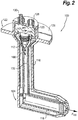
- At least one of fuel injector 100 and matched fuel injector 104 include a movable plunger 112 (shown in Fig. 2 ) for biasing fuel flow through the respective fuel injector. Movement of plunger 112 biasing fuel flow through fuel injector, creating the capability to offset temperature non-uniformity within combustion section 14 with variation in fuel flows provided to the combustion section 14, and thereby providing a mechanism to reduce temperature non-uniformity within combustion section 14.
- fuel system 102 includes a controller operatively connected to fuel injector 100 and matched fuel injector 104 and disposed in communication with one or more sensor 114, sensor 114 being arranged to provide information relating to temperature uniformity within combustion section 14 to controller 110.
- Fuel injector 100 includes a feed arm 116, a nozzle 118, plunger 112, and electrical actuator 120.
- Feed arm 116 has an inlet end 122 and an opposed outlet end 124.
- a mounting flange 126 extends about inlet end 122 for seating fuel injector 100 within combustion section 14 (shown in Fig. 1 ).
- a fuel inlet 128 and an electrical connector 130 are arranged on inlet end 122.
- a conduit 132 is defined within feed arm 116, extends between inlet end 122 and outlet end 124, and fluidly couples fuel inlet 128 with nozzle 118.
- Nozzle 118 is seated within outlet end 124 and is arranged to issue fuel flow F 100 into combustion section 14.
- plunger 112 is disposed within feed arm 116 and has a blunt segment 134, a tapered segment 136, and a constant diameter segment 138. Constant diameter segment 138 extends between blunt segment 134 and tapered segment 136, constant diameter segment 138 coupling tapered segment 136 to blunt segment 134. Plunger 112 also has male threads 140, which are engagable with female threads 146 of feed arm 116, and which extend about the periphery of plunger 112 and along at least a portion of constant diameter segment 138. Conduit 132 extends about plunger 112, plunger 112 being arranged to rotate with rotary movement 142 (shown in Fig. 2 ) relative to feed arm 116 about a rotation axis 144 (shown in Fig. 2 ) within conduit 132.
- Feed arm 116 has female threads 146.
- Female threads 146 of feed arm 116 are engagable with plunger 112 such that plunger 112 is threadably received within feed arm 116.
- rotary movement 142 shown in Fig. 2
- rotation axis 144 shown in Fig. 2
- plunger 112 to displace (i.e. translate) within conduit 132 relative to feed arm 116.
- female threads 146 are arranged about an inner periphery of a threaded annulus 148, which is fixed to feed arm 116, and are disposed within conduit 132.
- Plunger 112 is rotatably seated within threaded annulus 148, conduit 132 extending about threaded annulus 148 radially outward of rotation axis 144.
- a plurality of support members 150 span conduit 132 and fix threaded annulus 148 to feed arm 116, conduit 132 bounded by flow apertures defined between circumferentially adjacent support members 150.
- Conduit 132 tapers between a large flow area 152 and a small flow area 154.
- Small flow area 154 is defined between large flow area 152 and outlet end 124 (shown in Fig. 2 ) of feed arm 116.
- Large flow area 152 is defined between small flow area 152 and fuel inlet 128, and is fluidly upstream relative to small flow area 154 such that conduit 132 defines a plunger seat within feed arm 116.
- tapered segment 136 intersect at least a portion of large flow area 152 and/or small flow area 154 in an overlap, the magnitude of the overlap corresponding to translation of plunger 112 along rotation axis 144 (shown in Fig. 2 ).
- conduit 132 can include a thin-walled tube segment received within feed arm 116. An insulating gap can be defined between the thin-walled tube segment and the interior of feed arm 116.
- Electrical actuator 120 is operably connected to plunger 112.
- electrical actuator is arranged to rotate plunger 112 about rotation axis 144 (shown in Fig. 2 ) with rotary movement 142 (shown in Fig. 2 ).
- Rotary movement 142 translates plunger 112 along rotation axis 144 by operation of the threaded engagement of male threads 140 of plunger 112 and female threads 146 of feed arm 116.
- electrical actuator 120 includes a solenoid 156 electrically connected through electrical connector 130 with controller 110 (shown in Fig. 1 ).
- electrical actuator 120 can include a motor 158, motor 158 being connected through electrical connector 130 with controller 110.
- Motor 158 can be connected to plunger 112 through a rotary drive 160, and can be a rotary motor or a stepper motor by way of non-limiting example.
- plunger 112 is shown in a plunger first position 162.
- Plunger 112 is movably disposed within conduit 132 for biasing fuel flow F 100 through fuel injector 100 relative one or more other fuel injectors, e.g., matched fuel injector 104 (shown in Fig. 1 ) of fuel system 102 (shown in Fig. 1 ) with otherwise matching fuel flow. Biasing is accomplished by movement of plunger 112 between the plunger first position (shown in Figs. 4A and 4B ) and the plunger second position (shown in Figs.
- plunger 112 defines a relatively large effective flow area 168 when in plunger first position 162, plunger first position 162 being an axial placement of plunger 112 relative to feed arm 116 along conduit 132.
- Relatively large effective flow area 168 causes a relative large fuel flow F 100 to traverse fuel injector 100 and issue into combustion section 14 (shown in Fig. 1 ).
- rotary movement 142 by actuator 120 and associated translation 166 of plunger 112 increases the portion of relative small flow area 154 occupied by plunger 112. This defines a relatively small effective flow area 170, reducing the flow rate of fuel flow F 100 through conduit 132 of fuel injector 100, shown schematically with the relative length of the arrow associated with fuel flow F 100 in Fig. 4D as compared to the length of the arrow associated with fuel flow F 100 in Fig. 4B .
- movement of plunger 112 between plunger first position 162 (shown in Fig. 4A ) and plunger second position 164 can be in response to variation of temperature uniformity within gas turbine section 14 (shown in Fig. 1 ). It is contemplated that temperature uniformity be modulated by independent biasing of fuel flow F 100 through fuel injector 100 relative to other fuel injectors, e.g., matched fuel injector 104 (shown in Fig. 1 ).
- electrical actuator 120 can be appurtenant to fuel injector 100 or severable from fuel injector 100.
- fuel injector can have an appurtenant electrical actuator package 172, wherein electrical actuator 120 remains operably connected to plunger 112 during on-wing operation of gas turbine engine 10 (shown in Fig. 1 ).
- this provides on-wing adjustment capability to fuel injector 100.
- the adjustment capability is real-time, plunger 112 being movable according to temperature monitoring within gas turbine engine 10.
- electrical actuator 120 can be severable from fuel injector 100.
- fuel injector 100 has a severable electrical actuator package 174, wherein contemplated that electrical actuator 120 is removed from fuel injector 100 subsequent to adjustment of position of plunger 112.
- electrical actuator 120 can be installed for the engine 'green run' to dial in temperature uniformity in the engine as-built, and thereafter removed from the engine to save weight and reduce complexity.
- severable electrical actuator package 174 allow for re-installation of electrical actuator 120 when appropriate, such as during maintenance events or when change in temperature uniformity drive by a less readily correctable cause can be compensated for through fuel flow biasing of one or more fuel injectors in the engine fuel system.
- Method 200 includes flowing fuel through a feed arm, e.g., feed arm 116 (shown in Fig. 2 ) between an inlet end, e.g., inlet end 122 (shown in Fig. 2 ) and an outlet end, e.g., outlet end 124 (shown in Fig. 2 ), as shown with box 210.
- the fuel is flowed through a conduit, e.g., conduit 132 (shown in Fig. 2 ) defined within the fuel injector extending between the inlet end and outlet ends of the feed arm and about a plunger, e.g., plunger 112 (shown in Fig. 2 ), disposed within the conduit.
- the plunger is moved between a plunger first position, e.g., plunger first position 162 (shown in Fig. 4a ), and a plunger second position, e.g., plunger second position 164 (shown in Fig. 4b ), within the conduit, as shown with box 230.
- a plunger first position e.g., plunger first position 162 (shown in Fig. 4a )
- a plunger second position e.g., plunger second position 164 (shown in Fig. 4b )
- the plunger is moved between a plunger first position and the plunger second position. Movement of the plunger between the plunger first position and the plunger second position changes size of an effective flow area of the fuel injector, e.g., small flow area 154 (shown in Fig. 3 ), as shown with box 220.
- the change in the effective flow area changes fuel flow through the fuel injector relative to another fuel injector within the fuel system, independently biasing fuel flow through the fuel injector relative to one or more of the fuel injectors of the fuel system for a common fuel supply pressure.
- Biasing fuel flow can include, for example, decreasing fuel flow through a single fuel injector within the gas turbine engine fuel system from a relatively large fuel flow, e.g., fuel flow F 100 (shown in Fig. 4a ), to a smaller fuel flow, e.g., fuel flow F 100 (shown in Fig. 4b ). It is contemplated that fuel flow through the injector may become unmatched relative to that through one or more of the other fuel injectors in the fuel system.
- Moving the plunger can include rotating the plunger about a plunger axis, e.g., plunger rotation axis 144 (shown in Fig. 2 ), within the fuel injector, as shown with box 232.
- Moving the plunger can include translating the plunger along the plunger axis, e.g., via translation 166 (shown in Fig. 2 ), as shown with box 234.
- Moving the plunger can include both rotating and translating the plunger, such as through a threaded engagement of a plunger male threaded segment, e.g., male threads 140 (shown in Fig. 2 ), and female threads of the feed arm, e.g., female threads 146(as shown in Fig. 2 ).
- method 200 can include moving the plunger according to temperature uniformity within a gas turbine engine, e.g., within combustion section 14 (shown in Fig. 1 ) and/or turbine section 16 (shown in Fig. 1 ), as shown with box 240.
- the temperature can be acquired from sensors disposed in thermal communication with the turbine section, e.g., sensor 114 (shown in Fig. 1 ), the sensors being disposed in communication with a controller, e.g., controller 110 (shown in Fig. 1 ), to provide temperature information to the controller.
- Temperature uniformity can be determined, for example, at different angular positions relative to the turbine rotation axis and at a common longitudinal station.
- the measured temperature uniformity can be compared to a temperature uniformity limit, as shown with box 250, e.g., a temperature uniformity limit resident within a non-transitory machine-readable memory disposed in communication with the controller. Determination can be made as to whether the temperature uniformity is outside of the temperature range limit, as shown with decision box 260. When the temperature uniformity is outside of the temperature uniformity limit the plunger can be moved, as shown with arrow 262, and the resultant change in temperature uniformity determined by acquisition of a subsequent temperature determination as shown with arrow 264. When the temperature uniformity is within the temperature uniformity limit the plunger position can be retained, as shown with arrow 266.
- a temperature uniformity limit e.g., a temperature uniformity limit resident within a non-transitory machine-readable memory disposed in communication with the controller. Determination can be made as to whether the temperature uniformity is outside of the temperature range limit, as shown with decision box 260. When the temperature uniformity is outside of the temperature uniformity limit the plunger can be
- the method can terminate, as shown with box 270.
- an electronic actuator e.g., electronic actuator 120 (shown in Fig. 2 )
- the electronic actuator can remain operably connected to the fuel injector, as shown with arrow 290, thereby providing real-time biasing to fuel flow through the fuel injector.
- the methods and systems of the present disclosure provide for fuel injectors, fuel systems, gas turbine engines, and methods of controlling fuel flow in gas turbine engine fuel systems with superior properties including the capability to improve temperature uniformity by independently biasing fuel flow through one or more fuel injector relative to one or more otherwise flow-matched fuel injectors. While the apparatus and methods of the subject disclosure have been shown and described with reference to preferred embodiments, those skilled in the art will readily appreciate that change and/or modifications may be made thereto without departing from the scope of the subject disclosure.
Landscapes
- Engineering & Computer Science (AREA)
- Chemical & Material Sciences (AREA)
- Combustion & Propulsion (AREA)
- Mechanical Engineering (AREA)
- General Engineering & Computer Science (AREA)
- Fuel-Injection Apparatus (AREA)
Claims (15)
- Injecteur de carburant (100) pour un moteur à turbine à gaz (10), comprenant :un bras d'alimentation (116) à l'intérieur duquel un conduit (132) est défini, le conduit (132) s'étendant entre une extrémité d'entrée (122) et une extrémité de sortie (124) ; etun piston (112) disposé à l'intérieur du conduit (132) et pouvant se déplacer entre une première position de piston et une seconde position de piston,dans lequel le piston (112) et le conduit (132) définissent entre eux une zone d'écoulement (168) qui est plus petite dans la seconde position de piston que dans la première position de piston.
- Injecteur de carburant (100) selon la revendication 1, comprenant en outre un actionneur électrique (120) relié fonctionnellement au piston (112) et agencé pour déplacer le piston (112) par rapport au bras d'alimentation (116).
- Injecteur de carburant (100) selon la revendication 2, dans lequel l'actionneur électrique (120) fait partie de l'injecteur de carburant (100), ou
dans lequel l'actionneur électrique (120) peut être séparé du l'injecteur de carburant (100). - Injecteur de carburant (100) selon la revendication 2 ou 3, comprenant en outre un entraînement rotatif (160) couplant l'actionneur électrique (120) au piston (112) et conçu pour faire tourner le piston (112) par rapport au bras d'alimentation (116) .
- Injecteur de carburant (100) selon la revendication 2, 3 ou 4, dans lequel l'actionneur électrique (120) comprend un solénoïde (156), un moteur rotatif (158) ou un moteur pas à pas (158) .
- Injecteur de carburant (100) selon une quelconque revendication précédente, dans lequel le bras d'alimentation (116) a des filetages femelles (146) pouvant venir en prise avec le piston (112).
- Injecteur de carburant (100) selon la revendication 6, dans lequel le piston (112) a des filetages mâles (140) pouvant venir en prise avec les filetages femelles (146) du bras d'alimentation (116), ou
dans lequel le conduit (132) s'étend autour des filetages femelles (146). - Injecteur de carburant (100) selon une quelconque revendication précédente, dans lequel le conduit (132) se rétrécit entre une grande zone d'écoulement (152) et une petite zone d'écoulement (154), la petite zone d'écoulement (152) étant disposée entre la grande zone d'écoulement (154) et l'extrémité de sortie (124) du bras d'alimentation (116).
- Injecteur de carburant (100) selon une quelconque revendication précédente, dans lequel le piston (112) a un segment émoussé (134), un segment effilé (136) et un segment au diamètre constant (138), couplant le segment émoussé (134) au segment effilé (136).
- Injecteur de carburant (100) selon une quelconque revendication précédente, comprenant en outre un connecteur électrique (130) et un orifice d'entrée disposé à l'extrémité d'entrée (122) du bras d'alimentation (116), l'orifice d'entrée étant en communication fluidique avec le conduit (132),
comprenant en outre éventuellement un dispositif de commande (110) relié fonctionnellement au piston (112) par le connecteur électrique (130), le dispositif de commande (110) étant conçu pour faire tourner le piston (112) à l'intérieur du conduit (132) par rapport au bras d'alimentation (116). - Injecteur de carburant (100) selon une quelconque revendication précédente, comprenant en outre un anneau fileté (148) fixé à l'intérieur du bras d'alimentation (116) et positionnant le piston (112), le conduit (132) s'étendant autour de l'anneau fileté (148), une pluralité d'éléments de support (150) recouvrant le conduit (132) et couplant l'anneau fileté (148) au bras d'alimentation (116).
- Système de carburant (102) pour un moteur à turbine à gaz (10), comprenant :
des premier et second injecteurs de carburant (100) selon la revendication 1, dans lequel une zone d'écoulement de carburant de chacun du premier injecteur de carburant (100) et du second injecteur de carburant (100) sont réglables pour permettre au débit de carburant dans le premier injecteur de carburant (100) de solliciter le débit de carburant dans le premier injecteur de carburant (100) par rapport au débit de carburant dans le second injecteur de carburant (100). - Moteur à turbine à gaz (10) ayant un système de carburant (102) selon la revendication 12, comprenant :une section de combustion (14), etune section de turbine (16) en communication fluidique avec la section de combustion (14),dans lequel une plage de température dans la section de turbine (16) est plus faible lorsque le débit de carburant dans le premier injecteur de carburant (100) est sollicité par rapport au débit de carburant dans le second injecteur de carburant (100) que lorsque le débit de carburant dans le premier injecteur de carburant (100) correspond au débit de carburant dans le second injecteur de carburant (100).
- Moteur à turbine à gaz (10), selon la revendication 13, comprenant en outre un actionneur électrique (120) relié fonctionnellement au piston (112) et agencé pour faire tourner le piston (112) à l'intérieur du bras d'alimentation (116), ou
dans lequel ni le premier injecteur de carburant (100) ni le second injecteur de carburant (100) ne comprennent un actionneur électrique (120). - Procédé de commande du débit de carburant dans un système de carburant (102) d'un moteur à turbine à gaz (10), comprenant :l'écoulement de carburant dans un bras d'alimentation (116) ayant une extrémité d'entrée (122) et une extrémité de sortie (124) à travers un conduit (132) s'étendant entre l'extrémité d'entrée (122) et l'extrémité de sortie (124) du bras d'alimentation (116), etle déplacement d'un piston (112) disposé à l'intérieur du conduit (132) entre une première et une seconde positions à l'intérieur du conduit (132),dans lequel le mouvement entre la première et la seconde position réduit le débit de carburant dans l'injecteur de carburant (100) en réduisant une zone d'écoulement définie entre le piston (112) et le bras d'alimentation (116),dans lequel, éventuellement, le déplacement du piston (112) comprend la rotation du piston (112) par rapport au bras d'alimentation (116), et comprenant en outre le retrait de l'actionneur électrique (120) de l'injecteur de carburant (100).
Applications Claiming Priority (1)
| Application Number | Priority Date | Filing Date | Title |
|---|---|---|---|
| US15/714,597 US11053862B2 (en) | 2017-09-25 | 2017-09-25 | Electronic fuel control for gas turbine engines |
Publications (2)
| Publication Number | Publication Date |
|---|---|
| EP3460334A1 EP3460334A1 (fr) | 2019-03-27 |
| EP3460334B1 true EP3460334B1 (fr) | 2020-07-15 |
Family
ID=63713617
Family Applications (1)
| Application Number | Title | Priority Date | Filing Date |
|---|---|---|---|
| EP18196323.2A Active EP3460334B1 (fr) | 2017-09-25 | 2018-09-24 | Injecteur de carburant pour moteurs à turbine à gaz |
Country Status (2)
| Country | Link |
|---|---|
| US (1) | US11053862B2 (fr) |
| EP (1) | EP3460334B1 (fr) |
Families Citing this family (6)
| Publication number | Priority date | Publication date | Assignee | Title |
|---|---|---|---|---|
| US11377976B2 (en) * | 2018-12-19 | 2022-07-05 | Unison Industries, Llc | Surface cooler and method of forming |
| CN112460636B (zh) * | 2020-10-27 | 2022-04-08 | 中国船舶重工集团公司第七0三研究所 | 一种双油路单喷口双燃料喷嘴 |
| US11815025B2 (en) * | 2021-05-07 | 2023-11-14 | General Electric Company | Fuel nozzle |
| US12454915B2 (en) * | 2022-08-26 | 2025-10-28 | Hamilton Sundstrand Corporation | Force modification of passive valve spools for control of nozzles |
| US12305581B2 (en) * | 2022-08-26 | 2025-05-20 | Collins Engine Nozzles, Inc. | Proportional restriction of a secondary circuit of a fuel injector |
| US12454916B2 (en) | 2023-12-14 | 2025-10-28 | Collins Engine Nozzles, Inc. | Multi-component swirl valves |
Family Cites Families (28)
| Publication number | Priority date | Publication date | Assignee | Title |
|---|---|---|---|---|
| US3129891A (en) * | 1964-04-21 | Fuel nozzle | ||
| US2621477A (en) * | 1948-06-03 | 1952-12-16 | Power Jets Res & Dev Ltd | Combustion apparatus having valve controlled passages for preheating the fuel-air mixture |
| US3022954A (en) * | 1959-10-02 | 1962-02-27 | Parker Hannifin Corp | Variable area valve |
| US3662959A (en) | 1970-08-07 | 1972-05-16 | Parker Hannifin Corp | Fuel injection nozzle |
| US3695037A (en) * | 1970-09-08 | 1972-10-03 | Teledyne Ind | Shaft mounted fuel control |
| US4150539A (en) * | 1976-02-05 | 1979-04-24 | Avco Corporation | Low pollution combustor |
| DE2727795C2 (de) * | 1977-06-21 | 1984-08-09 | Daimler-Benz Ag, 7000 Stuttgart | Brennkammer für eine Gasturbine |
| GB2036296B (en) | 1978-11-20 | 1982-12-01 | Rolls Royce | Gas turbine |
| US4640093A (en) * | 1985-09-03 | 1987-02-03 | Allied Corporation | Fuel metering system |
| US5103636A (en) * | 1988-07-28 | 1992-04-14 | Williams International Corporation | Continuous flow fuel control system |
| US5000220A (en) * | 1988-10-14 | 1991-03-19 | Allied-Signal Inc. | Metering valve with follow-up servo |
| US5125227A (en) * | 1990-07-10 | 1992-06-30 | General Electric Company | Movable combustion system for a gas turbine |
| US5209893A (en) * | 1991-11-18 | 1993-05-11 | Southwire Company | Adjustable burner insert and method of adjusting same |
| US5243816A (en) | 1992-06-19 | 1993-09-14 | Fuel Systems Textron, Inc. | Self purging fuel injector |
| US6065451A (en) * | 1997-08-26 | 2000-05-23 | Alliedsignal Inc. | Bypass valve with constant force-versus-position actuator |
| US20040216782A1 (en) * | 2003-05-03 | 2004-11-04 | Mares E. Joseph | Gas turbine metering valve |
| US7114336B2 (en) * | 2004-01-30 | 2006-10-03 | Woodward Governor Company | Flow pulsing valve and fuel supply system for a turbine engine incorporating same |
| US8104258B1 (en) * | 2007-05-24 | 2012-01-31 | Jansen's Aircraft Systems Controls, Inc. | Fuel control system with metering purge valve for dual fuel turbine |
| US8291707B2 (en) * | 2008-08-18 | 2012-10-23 | Delavan Inc | Multi-stage check valve |
| US8636263B2 (en) | 2009-08-20 | 2014-01-28 | Delavan Inc | System and method for locking retention of valve components |
| US8123150B2 (en) * | 2010-03-30 | 2012-02-28 | General Electric Company | Variable area fuel nozzle |
| US9360219B2 (en) | 2010-12-30 | 2016-06-07 | Rolls-Royce North American Technologies, Inc. | Supercritical or mixed phase multi-port fuel injector |
| US9068510B2 (en) * | 2011-11-22 | 2015-06-30 | Delavan, Inc | Machined springs for injector applications |
| WO2015167422A1 (fr) * | 2014-04-28 | 2015-11-05 | Moog Inc. | Soupape de commande assistée par la pression d'une chambre de combustion de turbine |
| US10041681B2 (en) * | 2014-08-06 | 2018-08-07 | General Electric Company | Multi-stage combustor with a linear actuator controlling a variable air bypass |
| US10487957B2 (en) | 2015-08-13 | 2019-11-26 | Delavan Inc. | Fluid valves |
| GB201603054D0 (en) * | 2016-02-23 | 2016-04-06 | Rolls Royce Controls & Data Services Ltd | Combustion staging system |
| US20180163635A1 (en) * | 2016-12-13 | 2018-06-14 | Delavan Inc | Fluid valves |
-
2017
- 2017-09-25 US US15/714,597 patent/US11053862B2/en active Active
-
2018
- 2018-09-24 EP EP18196323.2A patent/EP3460334B1/fr active Active
Non-Patent Citations (1)
| Title |
|---|
| None * |
Also Published As
| Publication number | Publication date |
|---|---|
| EP3460334A1 (fr) | 2019-03-27 |
| US20190093569A1 (en) | 2019-03-28 |
| US11053862B2 (en) | 2021-07-06 |
Similar Documents
| Publication | Publication Date | Title |
|---|---|---|
| EP3460334B1 (fr) | Injecteur de carburant pour moteurs à turbine à gaz | |
| CN106051766B (zh) | 用于调整共振器的系统和方法 | |
| US8443608B2 (en) | Feed arm for a multiple circuit fuel injector | |
| CN105593117B (zh) | 桨距控制组件 | |
| EP2492473B1 (fr) | Système de carburant | |
| US6751942B2 (en) | System for controlling fuel flow to gas turbine engine | |
| EP3081783B1 (fr) | Collecteur de combustible à couplage thermique | |
| US10054052B2 (en) | Nacelle anti-ice system and method with equalized flow | |
| US11713724B1 (en) | Dual pump fuel delivery for an aircraft | |
| US20070214795A1 (en) | Continuous real time EGT margin control | |
| EP2902605A1 (fr) | Collecteur de carburant et dispositif d'injecteur de carburant pour turbine à gaz | |
| EP3192998A1 (fr) | Procédé et système de commande d'évent de sortie de compartiment d'aération de capot de générateur de gaz | |
| US9140190B2 (en) | Gas turbine engine fuel metering valve adapted to selectively receive fuel flow increase/decrease commands from the engine control and from the back-up fuel control | |
| EP3663566B1 (fr) | Soupape de purge de stabilité passive avec régulateur de pression de référence ajustable et capacité de surpassement à distance | |
| US9856836B2 (en) | Variable fluid flow apparatus with integrated filter | |
| US20150096641A1 (en) | Flow regulating apparatus | |
| US20150300503A1 (en) | Adjustable valve sleeve | |
| US20090260340A1 (en) | Combustor of a Turbine, a Method of Retro-Fitting a Combustor of a Turbine and a Method of Building a Combustor of a Turbine | |
| EP3102882B1 (fr) | Injecteur de carburant avec soupape | |
| EP1373686B1 (fr) | Module de commande de jeu de rotor | |
| EP2948660B1 (fr) | Centrale électrique à turbine à gaz pour la production d'énergie électrique et procédé d'actionnement de ladite centrale | |
| EP4015909B1 (fr) | Assemblage de buse de carburant avec agent de remplissage | |
| WO2009121350A1 (fr) | Compresseur de turbine à gaz | |
| EP3754231B1 (fr) | Régulateurs pneumatiques, vannes en ligne à commande pneumatique et procédés de refroidissement de régulateurs pneumatiques | |
| CN111636931A (zh) | 一种主汽调节联合汽阀 |
Legal Events
| Date | Code | Title | Description |
|---|---|---|---|
| PUAI | Public reference made under article 153(3) epc to a published international application that has entered the european phase |
Free format text: ORIGINAL CODE: 0009012 |
|
| STAA | Information on the status of an ep patent application or granted ep patent |
Free format text: STATUS: THE APPLICATION HAS BEEN PUBLISHED |
|
| AK | Designated contracting states |
Kind code of ref document: A1 Designated state(s): AL AT BE BG CH CY CZ DE DK EE ES FI FR GB GR HR HU IE IS IT LI LT LU LV MC MK MT NL NO PL PT RO RS SE SI SK SM TR |
|
| AX | Request for extension of the european patent |
Extension state: BA ME |
|
| STAA | Information on the status of an ep patent application or granted ep patent |
Free format text: STATUS: REQUEST FOR EXAMINATION WAS MADE |
|
| 17P | Request for examination filed |
Effective date: 20190924 |
|
| RBV | Designated contracting states (corrected) |
Designated state(s): AL AT BE BG CH CY CZ DE DK EE ES FI FR GB GR HR HU IE IS IT LI LT LU LV MC MK MT NL NO PL PT RO RS SE SI SK SM TR |
|
| GRAJ | Information related to disapproval of communication of intention to grant by the applicant or resumption of examination proceedings by the epo deleted |
Free format text: ORIGINAL CODE: EPIDOSDIGR1 |
|
| STAA | Information on the status of an ep patent application or granted ep patent |
Free format text: STATUS: GRANT OF PATENT IS INTENDED |
|
| GRAP | Despatch of communication of intention to grant a patent |
Free format text: ORIGINAL CODE: EPIDOSNIGR1 |
|
| INTG | Intention to grant announced |
Effective date: 20200131 |
|
| GRAS | Grant fee paid |
Free format text: ORIGINAL CODE: EPIDOSNIGR3 |
|
| GRAA | (expected) grant |
Free format text: ORIGINAL CODE: 0009210 |
|
| STAA | Information on the status of an ep patent application or granted ep patent |
Free format text: STATUS: THE PATENT HAS BEEN GRANTED |
|
| AK | Designated contracting states |
Kind code of ref document: B1 Designated state(s): AL AT BE BG CH CY CZ DE DK EE ES FI FR GB GR HR HU IE IS IT LI LT LU LV MC MK MT NL NO PL PT RO RS SE SI SK SM TR |
|
| REG | Reference to a national code |
Ref country code: CH Ref legal event code: EP Ref country code: GB Ref legal event code: FG4D |
|
| REG | Reference to a national code |
Ref country code: IE Ref legal event code: FG4D |
|
| REG | Reference to a national code |
Ref country code: DE Ref legal event code: R096 Ref document number: 602018006027 Country of ref document: DE |
|
| REG | Reference to a national code |
Ref country code: AT Ref legal event code: REF Ref document number: 1291453 Country of ref document: AT Kind code of ref document: T Effective date: 20200815 |
|
| REG | Reference to a national code |
Ref country code: LT Ref legal event code: MG4D |
|
| REG | Reference to a national code |
Ref country code: AT Ref legal event code: MK05 Ref document number: 1291453 Country of ref document: AT Kind code of ref document: T Effective date: 20200715 |
|
| REG | Reference to a national code |
Ref country code: NL Ref legal event code: MP Effective date: 20200715 |
|
| PG25 | Lapsed in a contracting state [announced via postgrant information from national office to epo] |
Ref country code: LT Free format text: LAPSE BECAUSE OF FAILURE TO SUBMIT A TRANSLATION OF THE DESCRIPTION OR TO PAY THE FEE WITHIN THE PRESCRIBED TIME-LIMIT Effective date: 20200715 Ref country code: FI Free format text: LAPSE BECAUSE OF FAILURE TO SUBMIT A TRANSLATION OF THE DESCRIPTION OR TO PAY THE FEE WITHIN THE PRESCRIBED TIME-LIMIT Effective date: 20200715 Ref country code: SE Free format text: LAPSE BECAUSE OF FAILURE TO SUBMIT A TRANSLATION OF THE DESCRIPTION OR TO PAY THE FEE WITHIN THE PRESCRIBED TIME-LIMIT Effective date: 20200715 Ref country code: HR Free format text: LAPSE BECAUSE OF FAILURE TO SUBMIT A TRANSLATION OF THE DESCRIPTION OR TO PAY THE FEE WITHIN THE PRESCRIBED TIME-LIMIT Effective date: 20200715 Ref country code: NO Free format text: LAPSE BECAUSE OF FAILURE TO SUBMIT A TRANSLATION OF THE DESCRIPTION OR TO PAY THE FEE WITHIN THE PRESCRIBED TIME-LIMIT Effective date: 20201015 Ref country code: GR Free format text: LAPSE BECAUSE OF FAILURE TO SUBMIT A TRANSLATION OF THE DESCRIPTION OR TO PAY THE FEE WITHIN THE PRESCRIBED TIME-LIMIT Effective date: 20201016 Ref country code: ES Free format text: LAPSE BECAUSE OF FAILURE TO SUBMIT A TRANSLATION OF THE DESCRIPTION OR TO PAY THE FEE WITHIN THE PRESCRIBED TIME-LIMIT Effective date: 20200715 Ref country code: AT Free format text: LAPSE BECAUSE OF FAILURE TO SUBMIT A TRANSLATION OF THE DESCRIPTION OR TO PAY THE FEE WITHIN THE PRESCRIBED TIME-LIMIT Effective date: 20200715 Ref country code: BG Free format text: LAPSE BECAUSE OF FAILURE TO SUBMIT A TRANSLATION OF THE DESCRIPTION OR TO PAY THE FEE WITHIN THE PRESCRIBED TIME-LIMIT Effective date: 20201015 Ref country code: PT Free format text: LAPSE BECAUSE OF FAILURE TO SUBMIT A TRANSLATION OF THE DESCRIPTION OR TO PAY THE FEE WITHIN THE PRESCRIBED TIME-LIMIT Effective date: 20201116 |
|
| PG25 | Lapsed in a contracting state [announced via postgrant information from national office to epo] |
Ref country code: RS Free format text: LAPSE BECAUSE OF FAILURE TO SUBMIT A TRANSLATION OF THE DESCRIPTION OR TO PAY THE FEE WITHIN THE PRESCRIBED TIME-LIMIT Effective date: 20200715 Ref country code: PL Free format text: LAPSE BECAUSE OF FAILURE TO SUBMIT A TRANSLATION OF THE DESCRIPTION OR TO PAY THE FEE WITHIN THE PRESCRIBED TIME-LIMIT Effective date: 20200715 Ref country code: LV Free format text: LAPSE BECAUSE OF FAILURE TO SUBMIT A TRANSLATION OF THE DESCRIPTION OR TO PAY THE FEE WITHIN THE PRESCRIBED TIME-LIMIT Effective date: 20200715 Ref country code: IS Free format text: LAPSE BECAUSE OF FAILURE TO SUBMIT A TRANSLATION OF THE DESCRIPTION OR TO PAY THE FEE WITHIN THE PRESCRIBED TIME-LIMIT Effective date: 20201115 |
|
| PG25 | Lapsed in a contracting state [announced via postgrant information from national office to epo] |
Ref country code: NL Free format text: LAPSE BECAUSE OF FAILURE TO SUBMIT A TRANSLATION OF THE DESCRIPTION OR TO PAY THE FEE WITHIN THE PRESCRIBED TIME-LIMIT Effective date: 20200715 |
|
| REG | Reference to a national code |
Ref country code: DE Ref legal event code: R097 Ref document number: 602018006027 Country of ref document: DE |
|
| PG25 | Lapsed in a contracting state [announced via postgrant information from national office to epo] |
Ref country code: CZ Free format text: LAPSE BECAUSE OF FAILURE TO SUBMIT A TRANSLATION OF THE DESCRIPTION OR TO PAY THE FEE WITHIN THE PRESCRIBED TIME-LIMIT Effective date: 20200715 Ref country code: DK Free format text: LAPSE BECAUSE OF FAILURE TO SUBMIT A TRANSLATION OF THE DESCRIPTION OR TO PAY THE FEE WITHIN THE PRESCRIBED TIME-LIMIT Effective date: 20200715 Ref country code: RO Free format text: LAPSE BECAUSE OF FAILURE TO SUBMIT A TRANSLATION OF THE DESCRIPTION OR TO PAY THE FEE WITHIN THE PRESCRIBED TIME-LIMIT Effective date: 20200715 Ref country code: EE Free format text: LAPSE BECAUSE OF FAILURE TO SUBMIT A TRANSLATION OF THE DESCRIPTION OR TO PAY THE FEE WITHIN THE PRESCRIBED TIME-LIMIT Effective date: 20200715 Ref country code: IT Free format text: LAPSE BECAUSE OF FAILURE TO SUBMIT A TRANSLATION OF THE DESCRIPTION OR TO PAY THE FEE WITHIN THE PRESCRIBED TIME-LIMIT Effective date: 20200715 Ref country code: SM Free format text: LAPSE BECAUSE OF FAILURE TO SUBMIT A TRANSLATION OF THE DESCRIPTION OR TO PAY THE FEE WITHIN THE PRESCRIBED TIME-LIMIT Effective date: 20200715 |
|
| PLBE | No opposition filed within time limit |
Free format text: ORIGINAL CODE: 0009261 |
|
| STAA | Information on the status of an ep patent application or granted ep patent |
Free format text: STATUS: NO OPPOSITION FILED WITHIN TIME LIMIT |
|
| PG25 | Lapsed in a contracting state [announced via postgrant information from national office to epo] |
Ref country code: AL Free format text: LAPSE BECAUSE OF FAILURE TO SUBMIT A TRANSLATION OF THE DESCRIPTION OR TO PAY THE FEE WITHIN THE PRESCRIBED TIME-LIMIT Effective date: 20200715 |
|
| REG | Reference to a national code |
Ref country code: BE Ref legal event code: MM Effective date: 20200930 |
|
| 26N | No opposition filed |
Effective date: 20210416 |
|
| PG25 | Lapsed in a contracting state [announced via postgrant information from national office to epo] |
Ref country code: LU Free format text: LAPSE BECAUSE OF NON-PAYMENT OF DUE FEES Effective date: 20200924 Ref country code: SK Free format text: LAPSE BECAUSE OF FAILURE TO SUBMIT A TRANSLATION OF THE DESCRIPTION OR TO PAY THE FEE WITHIN THE PRESCRIBED TIME-LIMIT Effective date: 20200715 |
|
| PG25 | Lapsed in a contracting state [announced via postgrant information from national office to epo] |
Ref country code: SI Free format text: LAPSE BECAUSE OF FAILURE TO SUBMIT A TRANSLATION OF THE DESCRIPTION OR TO PAY THE FEE WITHIN THE PRESCRIBED TIME-LIMIT Effective date: 20200715 Ref country code: IE Free format text: LAPSE BECAUSE OF NON-PAYMENT OF DUE FEES Effective date: 20200924 Ref country code: BE Free format text: LAPSE BECAUSE OF NON-PAYMENT OF DUE FEES Effective date: 20200930 |
|
| REG | Reference to a national code |
Ref country code: CH Ref legal event code: PL |
|
| PG25 | Lapsed in a contracting state [announced via postgrant information from national office to epo] |
Ref country code: TR Free format text: LAPSE BECAUSE OF FAILURE TO SUBMIT A TRANSLATION OF THE DESCRIPTION OR TO PAY THE FEE WITHIN THE PRESCRIBED TIME-LIMIT Effective date: 20200715 Ref country code: MT Free format text: LAPSE BECAUSE OF FAILURE TO SUBMIT A TRANSLATION OF THE DESCRIPTION OR TO PAY THE FEE WITHIN THE PRESCRIBED TIME-LIMIT Effective date: 20200715 Ref country code: CY Free format text: LAPSE BECAUSE OF FAILURE TO SUBMIT A TRANSLATION OF THE DESCRIPTION OR TO PAY THE FEE WITHIN THE PRESCRIBED TIME-LIMIT Effective date: 20200715 |
|
| PG25 | Lapsed in a contracting state [announced via postgrant information from national office to epo] |
Ref country code: MK Free format text: LAPSE BECAUSE OF FAILURE TO SUBMIT A TRANSLATION OF THE DESCRIPTION OR TO PAY THE FEE WITHIN THE PRESCRIBED TIME-LIMIT Effective date: 20200715 Ref country code: MC Free format text: LAPSE BECAUSE OF FAILURE TO SUBMIT A TRANSLATION OF THE DESCRIPTION OR TO PAY THE FEE WITHIN THE PRESCRIBED TIME-LIMIT Effective date: 20200715 |
|
| PG25 | Lapsed in a contracting state [announced via postgrant information from national office to epo] |
Ref country code: LI Free format text: LAPSE BECAUSE OF NON-PAYMENT OF DUE FEES Effective date: 20210930 Ref country code: CH Free format text: LAPSE BECAUSE OF NON-PAYMENT OF DUE FEES Effective date: 20210930 |
|
| P01 | Opt-out of the competence of the unified patent court (upc) registered |
Effective date: 20230530 |
|
| PGFP | Annual fee paid to national office [announced via postgrant information from national office to epo] |
Ref country code: DE Payment date: 20250820 Year of fee payment: 8 |
|
| PGFP | Annual fee paid to national office [announced via postgrant information from national office to epo] |
Ref country code: GB Payment date: 20250820 Year of fee payment: 8 |
|
| PGFP | Annual fee paid to national office [announced via postgrant information from national office to epo] |
Ref country code: FR Payment date: 20250821 Year of fee payment: 8 |