EP3461966A1 - Dispositif de marches ou de marches d'escalier pour surfaces suspendues à inclinaison différente - Google Patents
Dispositif de marches ou de marches d'escalier pour surfaces suspendues à inclinaison différente Download PDFInfo
- Publication number
- EP3461966A1 EP3461966A1 EP18196760.5A EP18196760A EP3461966A1 EP 3461966 A1 EP3461966 A1 EP 3461966A1 EP 18196760 A EP18196760 A EP 18196760A EP 3461966 A1 EP3461966 A1 EP 3461966A1
- Authority
- EP
- European Patent Office
- Prior art keywords
- tread
- slope surface
- limiting element
- stepping
- front foot
- Prior art date
- Legal status (The legal status is an assumption and is not a legal conclusion. Google has not performed a legal analysis and makes no representation as to the accuracy of the status listed.)
- Granted
Links
Images


Classifications
-
- E—FIXED CONSTRUCTIONS
- E06—DOORS, WINDOWS, SHUTTERS, OR ROLLER BLINDS IN GENERAL; LADDERS
- E06C—LADDERS
- E06C7/00—Component parts, supporting parts, or accessories
- E06C7/42—Ladder feet; Supports therefor
- E06C7/44—Means for mounting ladders on uneven ground
-
- E—FIXED CONSTRUCTIONS
- E04—BUILDING
- E04F—FINISHING WORK ON BUILDINGS, e.g. STAIRS, FLOORS
- E04F11/00—Stairways, ramps, or like structures; Balustrades; Handrails
- E04F11/02—Stairways; Layouts thereof
- E04F11/104—Treads
- E04F11/1041—Treads having means to adjust the height, the depth and/or the slope of the stair steps
-
- E—FIXED CONSTRUCTIONS
- E04—BUILDING
- E04G—SCAFFOLDING; FORMS; SHUTTERING; BUILDING IMPLEMENTS OR AIDS, OR THEIR USE; HANDLING BUILDING MATERIALS ON THE SITE; REPAIRING, BREAKING-UP OR OTHER WORK ON EXISTING BUILDINGS
- E04G27/00—Temporary arrangements for giving access from one level to another for men or vehicles, e.g. steps, ramps
-
- E—FIXED CONSTRUCTIONS
- E04—BUILDING
- E04G—SCAFFOLDING; FORMS; SHUTTERING; BUILDING IMPLEMENTS OR AIDS, OR THEIR USE; HANDLING BUILDING MATERIALS ON THE SITE; REPAIRING, BREAKING-UP OR OTHER WORK ON EXISTING BUILDINGS
- E04G3/00—Scaffolds essentially supported by building constructions, e.g. adjustable in height
- E04G3/24—Scaffolds essentially supported by building constructions, e.g. adjustable in height specially adapted for particular parts of buildings or for buildings of particular shape, e.g. chimney stacks or pylons
- E04G3/26—Scaffolds essentially supported by building constructions, e.g. adjustable in height specially adapted for particular parts of buildings or for buildings of particular shape, e.g. chimney stacks or pylons specially adapted for working on roofs
-
- E—FIXED CONSTRUCTIONS
- E04—BUILDING
- E04F—FINISHING WORK ON BUILDINGS, e.g. STAIRS, FLOORS
- E04F11/00—Stairways, ramps, or like structures; Balustrades; Handrails
- E04F11/02—Stairways; Layouts thereof
- E04F11/104—Treads
- E04F11/112—Treads of metal or with an upper layer of metal
Definitions
- the invention relates to a step or tread arrangement for free laying on a slope, according to the preambles of claims 1, 3 and 5 and methods for free installation of such a tread or step arrangement according to claims 2, 4 and 6. Furthermore, the invention also relates a step or step system, in particular a ground-based staircase, consisting of a plurality of such tread or step arrangements according to claim 17.
- the generic EP 0 753 645 A1 proposes the generic EP 0 753 645 A1 a mobile, freely deployable single step in the form of a one-piece, angularly bent element before, one leg of which forms a tread plate, and which is provided at at least one end with means for adhering or clinging to the ground.
- the means for clawing the terrain are formed by protruding from a free leg edge claws.
- the angle of the tread plate in relation to the slope surface is determined by the geometry of the legs. For big ones Slope tendencies it may happen that the tread is deviating from an ideal horizontal position also undesirable strongly inclined.
- the invention is based on the object to further develop a stepping or stepping arrangement for free laying on a slope surface of the type mentioned that it can be adapted to different slopes with simple and inexpensive means. Furthermore, a method for free installation of such a tread or step arrangement and a step or step system, in particular a ground-based stairs should be specified, which consists of several such tread or step arrangements.
- the invention is according to a first aspect of a tread arrangement for free laying on a slope, comprising at least one tread or staircase body with a provided for entering by at least one foot of a person tread, and at least two in the use position front, from the tread after downwardly projecting and spaced transversely from each other foot parts, which have measured from the tread each having a first vertical extent, wherein the free ends of at least the front foot portions are provided for at least partially penetrating the slope surface, at least one in use position rear, from the tread bottom projecting foot part, which has measured from the tread a second vertical extent, wherein the first vertical extent is greater than the second vertical extent.
- a plurality of first, on each different (vertical) level arranged passage openings and in a second front foot part of the front foot parts a plurality of second, arranged on each different (vertical) level through holes are formed, and at least one rod-shaped limiting element for selectively inserting into a certain first passage opening of the plurality of first passage openings and in a certain second passage opening of the plurality of second passage openings is provided that by the inserted into the specific first passage opening and the specific second passage opening limiting element an intrusion of the at least two front foot parts into the slope surface is limited to a (vertical) level which corresponds to the level of the delimiting element.
- the specific first through-opening and the specific second through-opening can in particular be aligned through-openings, so that then the limiting element is aligned horizontally.
- certain first through-hole and the particular second through-hole may be non-aligned through holes, and then the boundary member is slanted with respect to the horizontal.
- the passage openings may also be formed slot-like, to allow such an oblique orientation of the limiting element.
- the invention is based on a second aspect of a tread arrangement for free laying on a slope, comprising at least one tread or staircase body with a provided for entering by at least one foot of a person tread, as well as at least one in the use position, from the tread after downwardly projecting foot part, which has measured from the tread a first vertical extent, at least two in the use position rear, from the tread surface downwardly away and spaced from each other in the transverse direction foot portions, which measured from the tread each having a second vertical extent, said free ends of at least the rear foot parts for at least partially penetrating the slope surface are provided, wherein the first vertical extent is greater than the second vertical extent.
- a plurality of third, arranged on each different (vertical) level passage opening and in a second rear foot part of the rear foot parts a fourth, each arranged on different (vertical) level through holes are formed, and at least one rod-shaped limiting element is provided for selectively inserting loose in a certain third through hole of the plurality of third through holes and in a certain fourth through hole of the plurality of fourth through holes that through the in the certain third through hole and in the specific fourth Through opening inserted limiting element penetration of the free ends of the at least two rear foot parts is limited in the slope surface on a (vertical) level, which the (vertical) level of the Begrenzu ngselements corresponds.
- the specific third through-opening and the specific fourth through-opening can in particular be aligned through-openings, so that then the limiting element is aligned horizontally.
- certain third through-hole and the certain fourth through-hole may be non-aligned through holes, and then the boundary member is obliquely aligned with respect to the horizontal.
- the invention is based on a third aspect of a tread arrangement for free laying on a slope, comprising at least one tread or staircase body with a provided for entering by at least one foot of a person tread, and with at least two in the use position front, from the tread after downwardly projecting foot portions having a first vertical extent measured from the tread surface, the free ends of the front foot portions being provided for at least partial penetration into the slope surface, at least two rearward, downwardly projecting footboards away from the tread, each having a second vertical extent measured from the tread surface, the free ends of at least the rear leg portions being for at least partially penetrating the slope surface; wherein the first vertical extent is greater than the second vertical extent.
- the specific fifth through-opening and the specific sixth through-opening can in particular be through-openings aligned with one another, so that then the limiting element is aligned horizontally.
- certain fifth passage opening and the certain sixth passage opening may not be aligned Be through holes, in which case the limiting element is aligned obliquely with respect to the horizontal.
- the principle of the first aspect realized in the front foot parts is transmitted to a front and a rear foot part on at least one side of the tread or staircase body.
- the limiting element used in the particular through holes prevents the free ends of the respective foot portions of the tread or staircase body from being subjected to stress, e.g. penetrate deeper into the (soft) slope surface by the appearance of a person, as this is predetermined by the respective vertical level of the limiting element.
- the limiting element can be used in certain through holes such that at the then positioned on the slope surface tread or step assembly the tread (almost) is aligned horizontally and therefore slipping or slipping of the foot of a person from the Tread is prevented.
- “Loose insertion” means that the limiting element in the unassembled state of the tread or step assembly is loosely or playfully accommodated in the through holes, so that the limiting element can be easily inserted or inserted into the through holes, while in the assembled state or in the use position of the kick or staircase arrangement on the slope surface, the limiting element is held by frictional forces in the through holes, which are caused in particular by weight forces of the tread or stair step using people and / or by the longitudinal forces due to the penetration of the free end of the foot parts in the slope.
- the outer diameters or outer dimensions of the limiting elements are smaller than the inner diameters or inner dimensions of the through openings.
- the invention is therefore applicable to slope surfaces, in which the free ends of at least the foot parts can penetrate under load of the tread a piece to fix the tread or staircase body in the slope.
- the cross sections of the ends of the foot parts may be designed, for example, with a relatively small cross section.
- the invention can be realized by simple means, as only the respective foot parts are to be provided with through holes and at least one rod-shaped limiting element is provided.
- the passage openings are arranged equidistantly on a foot part.
- a particularly effective limitation of the penetration of the free ends of the foot parts into the slope surface is achieved, in particular, by the fact that the at least one rod-shaped limiting element projects laterally a little way out of the passage openings and projects laterally beyond the respective foot parts.
- the at least one rod-shaped limiting element and the passage openings may each have a circular cross-section.
- the rod-shaped limiting element may have a circular cross section and the passage openings may have a slot cross section.
- any desired cross-section of the rod-shaped limiting element and the passage openings in particular also a square or rectangular cross-section, is conceivable, as long as the at least one Containing element play or loose in the through holes can be added.
- a particularly cost-effective tread arrangement results when the rod-shaped limiting element is formed by a rod of a reinforced concrete reinforcement.
- Such rods are widely used in commerce and therefore inexpensive.
- the tread or staircase body is made of sheet steel or aluminum. Also conceivable is an embodiment as injection molded plastic.
- the surface of the tread provided for entering is provided with a non-slip support.
- a non-slip pad may in particular consist of a glued-on foil with non-slip properties.
- the tread can also be designed as checker plate.
- the tread can also have through holes with serrated edges, the tines projecting from the tread.
- tread or staircase body includes a one-piece sheet steel part or is formed by such a one-piece sheet steel part, wherein the at least two front foot parts and the at least one rear foot part are folded from the tread ,
- a high rigidity of the tread or staircase body arises when the at least one rear foot part and the front foot parts preferably each have an L-shaped cross-section.
- An even higher rigidity of the tread or stair tread body can be achieved when viewed in the use position of the tread or staircase body each side a web portion is folded, which each collides with a front foot and a rear foot in a miter. Then, when the tread surface is loaded, a respective front foot part and a rear foot part can be supported on a lateral web part via the miter.
- the web part can be riveted to the rear foot part and / or to the front foot part respectively in the miter.
- the tread surface has a planar extent that only a foot of a person can occur there.
- the tread may also have a greater width, as seen in the manner of a step in the transverse direction, so that, for example, a person with both feet can step on the tread at the same time.
- a tread plate cassette for inserting a tread plate may be provided in the region of the tread, wherein the tread plate is arranged in the inserted state in the use position above and parallel to the tread surface.
- the tread cassette is preferably connected to the tread or staircase body, in particular with the tread, for example by screwing.
- the tread cassette may have at least two and at most three profiles with U-shaped cross-section and a bottom, each such profile is disposed on one edge of the four edges of the floor and another executed without a profile edge fixing means for fixing the tread plate in the tread cassette has.
- the fixing means may have at least one arranged on the other edge of the bottom of the footboard cassette or at the edge of the tread so bendable tab that in a first position of at least a tab insertion of the tread plate in the tread cassette possible and in a second, relative to the first layer bent position of the at least one tab, the tread plate is fixed within the tread cassette.
- the tread plate can be made of wood, (artificial or natural) stone or plastic, or even of a material mix, depending on the optical requirement.
- the invention also relates to tread or step system, in particular a ground-based staircase, consisting of several above-described tread or stair tread arrangements.
- connecting means may be provided, through which a plurality of tread or stairstep arrangements can be connected to one another.
- the connecting means may comprise at least one connecting profile, of which seen in the operating position on a first side at least a first engagement element and on a side facing away from the first side second side at least a second engagement member projects away, wherein the first engagement member engages in a passage opening of a first step or step assembly and the second engagement member in a through hole of a second, different from the first tread or step assembly tread or step assembly, whereby the first step - or stair-step arrangement and the second tread or stair-step arrangement are connected to each other in particular substantially without viewing gap.
- first engagement element and / or the second engagement element can also be hook-shaped.
- the plurality of tread or stepping arrangements can be staggered laterally and vertically relative to the slope surface such that their arrangement of treading order corresponds to a person who climbs the slope.
- the plurality of steps can be arranged on the slope in a row one behind the other, so that they are in alignment stand.
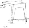
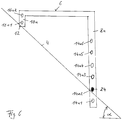
- Fig. 1 to Fig. 6 are illustrations of a preferred embodiment of a tread or step assembly 2 with a tread or staircase body 1 for free laying on a sloping slope 4 shown.
- the slope surface 4 assumes, for example, a first slope angle ⁇ with respect to a horizontal surface and consists here, for example, of relatively soft soil, so that under pressure narrow bodies can easily penetrate into the slope surface 4.
- the tread or staircase body 1 has a tread surface 6 provided for entry by, for example, only one foot of a person, and here, for example, two foot portions 8a, 8b which are forwardly projecting from the tread surface 6 and spaced apart transversely in the position of use each of the tread surface 6 has a first vertical extent h1 ( Figure 3 ).
- Fig. 1 In the use position of Fig. 1 that is, when the tread or step assembly 2 is attached to or in the slope surface 4, then the front foot portions 8a, 8b form downhill facing foot portions and the rear leg portions 10a, 10b provide uphill facing foot portions.
- the free ends 12 of the two front foot parts 8a, 8b and the two rear foot parts 10a, 10b are respectively provided for at least partial penetration into the slope surface 4 when the tread surface 6 is loaded.
- the tread or staircase body 1 On the basis of in Fig. 1 shown situation, the tread or staircase body 1 but still unloaded, so that the free ends 12 of the foot parts 8a, 8b and 10a, 10b still rest on the slope surface 4 only, but not yet penetrated into this.
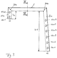
- a first front foot part 8a of the front foot parts 8a, 8b has a plurality of first through openings 14a1 to 14a6 each having a different level position and a second front foot part 8b of the front foot parts 8a, 8b second, for example each with the first through openings 14a1 to 14a6 in the transverse direction Seen aligned through hole 14b1 to 14b6, for example, each formed equidistantly.
- the first through holes 14a1 to 14a6 and the second through holes 14b1 to 14b6 are different from each other by a different vertical level at the front foot parts 8a, 8b.
- Fig. 1A . Fig. 1B . Fig. 1C . Fig. 5 . Fig. 6 and Fig. 7 show is a rod-shaped limiting element 24 for optional lateral and loose insertion into a specific first through-opening 14a1, 14a2, 14a3, 14a4, 14a5 or 14a6 and into a specific second through-opening 14b1, 14b2, 14b3, 14b4, 14b5 or 14b6, so that by the limiting element 24 penetration of the free ends 12th the front foot parts 8a, 8b is limited in the slope surface 4 to a vertical level, which corresponds to the vertical level of the inserted limiting element 24.
- the limiting element 24 is inserted, for example, through the through openings 14a2 and 14b2, which are aligned with one another from below, the ends of the delimiting element 24 protruding, for example, a little way laterally from the passage openings 14a2, 14b2.
- the limiting element 24 in certain through holes 14a1, 14a2, 14a3, 14a4, 14a5 or 14a6 or 14b1, 14b2, 14b3, 14b4, 14b5 or 14b6 optionally be used such that at the then the tread surface 4 positioned tread assembly 2, the tread surface 6 (nearly) is aligned horizontally and therefore slipping or slipping of the foot of a person is prevented when she puts her foot on the tread surface 6.
- Fig. 1B shows a situation in which the limiting element 24, for example, not as in Fig. 1A is inserted into each other with horizontally aligned passage openings 14a2 and 14b2, but in mutually just not aligned through holes 14a4 and 14b2. As a result, the limiting element is then in an angle with respect to the horizontal or oblique position, which is due to an adaptation to the shape of the slope surface 4 no.
- Fig. 1C shows a situation in which the limiting element 24, for example, in the first front foot part 8a and the second front foot part 8b as in Fig. 1A is inserted in first and second through holes 14a2, 14b2, each with the same level position.
- the two rear foot parts 10a and 10b also each have, for example, two second through openings 16a1, 16a2 or 16b1, 16b2, each with a different level position, of which one pair 16a1, 16b1 or 16a2, 16b2 is aligned horizontally with each other.
- a further limiting element 24a is then inserted, for example, through the lowermost through-openings 16a1 and 16b1.
- the limiting elements 24, 24a are then in a respective horizontal position.
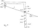
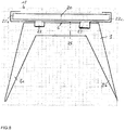
- Fig. 7 shows, for example, the tread or step assembly 2 as it is attached to or in a slope surface 4, which has a second, relative to the first slope angle ⁇ smaller slope angle ⁇ with respect to a horizontal surface.
- the limiting element 24 is inserted, for example, in the second pair of passage openings 14a5 and 14b5 seen from above in the two front foot parts 8a, 8b. Then, the proportion of the free ends 12 of the front foot parts 8a, 8b, which protrude into the slope surface 4 or are inserted therein, relatively large.
- Fig. 1A For free laying of the tread assembly 2 on the slope surface 4 is therefore with reference to Fig. 1A First, the rod-shaped limiting element 24 in certain through holes 14a2, 14b2 in the front foot parts 8a, 8b depending on the inclination of the slope surface 4 loosely inserted. Then the tread or staircase body 1 is positioned with the inserted limiting element 24 on the slope surface 4 such that the two front foot parts 8a, 8b turned down the slope and the two rear foot parts 10a, 10b are turned uphill.
- the rod-shaped limiting element 24 and the passage openings 14a, 14b may each have a circular cross-section. It is conceivable, however, any cross-section of the rod-shaped limiting element 24 and the through holes 14a, 14b, in particular a square or rectangular cross-section.
- the rod-shaped limiting element 24 is formed here, for example, by a rod of a reinforced concrete reinforcement.
- the provided for entering surface of the tread surface 6 may be provided with a non-slip support 26.
- a non-slip support 26 may in particular consist of a glued foil with non-slip properties.
- the tread surface 6 may also have through-holes 19 with serrated wheels, the tines projecting from the tread surface 6 and then likewise representing a slip-resistance ( Fig. 1 ).
- an even better adjustment of the orientation or inclination of the tread surface 6 of the tread or staircase body 1 can be achieved by in a first rear foot portion 10a of the rear leg portions 10a, 10b third through holes 16a1, 16a2 and in a second rear leg portion 10b of rear foot portions 10a, 10b fourth, with the third through holes, for example, in the transverse direction aligned through holes 16b1, 16b2 are formed, wherein the third through holes 16a1, 16a2 and the fourth through holes 16b1, 16b2 through a different vertical level at the rear foot parts 10a, 10b differ.
- the further limiting element 24a can then be inserted, for example, through the lowermost through-openings 16a1 and 16b1.
- the limiting elements 24, 24a are then in a respective horizontal position.
- the penetration depth of the free ends 12 limited in the slope surface 4 and thereby the tread surface 6 depending on the inclination of the slope surface 4 in the operating position of the tread or Stair step arrangement 2 ideally be aligned horizontally.
- a particularly cost-effective production of the tread or step assembly 2 is also obtained when the tread or staircase body 1 is formed as here by a one-piece sheet steel part, wherein the front foot portions 8a, 8b and the rear foot portions 10a, 10b bent from the tread surface 6 are, in particular on the basis of Fig. 1 to Fig. 5 is easy to imagine.
- the rear foot parts 10a, 10b and the front foot parts 8a, 8b preferably each have an L-shaped cross-section. From the tread or staircase body 1 is further laterally each a web portion 28a, 28b folded, which abuts with the front foot parts 8a, 8b and the rear foot parts 10a, 10b each in a miter 30a, 30b, 30c, 30d. Then, when the tread surface 6 is loaded, the two front foot parts 8a, 8b and the two rear foot parts 10a, 10b can each be supported on the lateral web parts via the mitres 30a, 30b, 30c, 30d.
- the tread surface 6 has a planar extent that only a foot of a person can occur there.
- the tread surface 6 can also have a greater width, as seen in the manner of a step in the transverse direction, so that, for example, a person with both feet can step on the tread 6 at the same time.
- the invention also relates to a tread or step system, in particular a floor or slope-mounted stairs consisting of several above-described tread or step assemblies 2, which are mounted on the slope 4 so that the slope surface 4 is accessible.
- the plurality of tread or step assemblies 2 can then, for example, laterally and also relative to the vertical level on the slope surface 4 are arranged staggered such that their arrangement of the sequence of steps corresponds to a person who rises the slope surface 4.
- the multiple tread or step assemblies 2 on the slope 4 in the manner of stairs in a Row are arranged one behind the other so that they are in alignment with each other.
- a locally or continuously curved course of the ground or slope-bound stairs can be provided, depending on the individual step or step arrangements 2 on the slope 4 are arranged relative to each other.
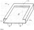
- a tread plate cassette 18, for example, made of sheet steel for insertion of a tread plate 20 be secured, for example by screwing, wherein the tread plate 20 is arranged in the inserted state in the use position above and parallel to the tread surface 6.
- the tread plate cassette 18 for example, made in one piece from sheet steel, may have a rectangular or square cross-section and have, for example, three adjoining profiles 22a, 22b, 22c, each having a U-shaped cross section and a bottom 25 ( Fig. 9 ), wherein in each case such a profile 22 is arranged on an edge of the bottom 25 and the fourth edge is provided without such a profile, but fixing means 23 for fixing the inserted into the profiles 22a to 22c tread plate 20 in the tread cassette 18 has ,
- the fixing means on the fourth edge of the bottom 25 of the tread cassette 18 arranged such bendable (plate) tabs 23 have that in a first position of the tabs insertion of the tread plate 20 in the tread cassette 18 is possible, such as Fig. 8 and Fig. 9 show, and in a second, compared to the first layer here, for example, upward bent position of the tabs 23, the tread plate 20 is fixed within the tread cassette 18.
- the tabs 23 may in turn be made in one piece with the footboard cassette 18 made of sheet steel.
- the tread plate 20 may be made of wood, stone or plastic, for example, to produce a desired visual impression.
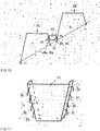
- releasable connection means may be provided, by which a plurality of tread or step assemblies 2a, 2b are connected to each other, as from 10 and FIG. 11 evident.
- the connecting means may be formed by an example trapezoidal connection profile 32, seen from the use position on a first side first engagement elements, for example in the form of first hook 34 and second side facing away from the second side second engagement elements, for example in the form of second hook 36th stick out ( Fig. 11 ).
- first hook 34 of the then two connection profiles 32 for example, in through holes of the rear foot parts 10a, 10b of a first tread or step assembly 2a and the second hooks 36 in through holes of the front foot parts 8a, 8b of a second treadmill other than the first tread or step assembly 2a Engage staircase assembly 2b.
- the here, for example, trapezoidal connection profile 32 is preferably carried out such that the first step or step assembly 2a and the second tread or step assembly 2b are connected to each other in particular substantially without viewing gap.
- the hooks 34, 36 of the connection profile 32 are then disengaged from the through openings of the foot parts 8a, 8b and 10a, 10b.
Landscapes
- Engineering & Computer Science (AREA)
- Architecture (AREA)
- Civil Engineering (AREA)
- Structural Engineering (AREA)
- Mechanical Engineering (AREA)
- Steps, Ramps, And Handrails (AREA)
- Tires In General (AREA)
Applications Claiming Priority (1)
| Application Number | Priority Date | Filing Date | Title |
|---|---|---|---|
| DE202017005022.6U DE202017005022U1 (de) | 2017-09-27 | 2017-09-27 | Trittstufenanordnung für Hangflächen mit unterschiedlicher Neigung |
Publications (2)
| Publication Number | Publication Date |
|---|---|
| EP3461966A1 true EP3461966A1 (fr) | 2019-04-03 |
| EP3461966B1 EP3461966B1 (fr) | 2020-07-08 |
Family
ID=60579159
Family Applications (1)
| Application Number | Title | Priority Date | Filing Date |
|---|---|---|---|
| EP18196760.5A Active EP3461966B1 (fr) | 2017-09-27 | 2018-09-26 | Dispositif de marches ou de marches d'escalier pour surfaces suspendues à inclinaison différente |
Country Status (2)
| Country | Link |
|---|---|
| EP (1) | EP3461966B1 (fr) |
| DE (1) | DE202017005022U1 (fr) |
Cited By (2)
| Publication number | Priority date | Publication date | Assignee | Title |
|---|---|---|---|---|
| EP3805479A1 (fr) | 2019-10-11 | 2021-04-14 | Franz Bürscher | Module d'appui pour la partie verticale d'une marche |
| EP4137654A1 (fr) * | 2021-08-21 | 2023-02-22 | Bürscher, Franz DI | Dispositif support |
Citations (5)
| Publication number | Priority date | Publication date | Assignee | Title |
|---|---|---|---|---|
| US4520897A (en) * | 1984-05-14 | 1985-06-04 | Gebo George B | Portable steps |
| DE9316169U1 (de) * | 1992-11-26 | 1994-02-03 | Wychgram, Ursula, 82418 Murnau | Trittflächenelement |
| EP0753645A1 (fr) * | 1995-07-10 | 1997-01-15 | Scheuchzer, Roland, Dr.rer.pol. | Dispositif d'assistance pour travailler sur des terrains inclinés |
| US20040255406A1 (en) * | 2003-06-19 | 2004-12-23 | Schweitzer Kathleen M. | Methods and apparatus for a step mounting system |
| DE202014100052U1 (de) * | 2013-12-10 | 2014-12-11 | Mts Metallbau Thomas Schneider Gmbh | Trittstufe |
-
2017
- 2017-09-27 DE DE202017005022.6U patent/DE202017005022U1/de active Active
-
2018
- 2018-09-26 EP EP18196760.5A patent/EP3461966B1/fr active Active
Patent Citations (5)
| Publication number | Priority date | Publication date | Assignee | Title |
|---|---|---|---|---|
| US4520897A (en) * | 1984-05-14 | 1985-06-04 | Gebo George B | Portable steps |
| DE9316169U1 (de) * | 1992-11-26 | 1994-02-03 | Wychgram, Ursula, 82418 Murnau | Trittflächenelement |
| EP0753645A1 (fr) * | 1995-07-10 | 1997-01-15 | Scheuchzer, Roland, Dr.rer.pol. | Dispositif d'assistance pour travailler sur des terrains inclinés |
| US20040255406A1 (en) * | 2003-06-19 | 2004-12-23 | Schweitzer Kathleen M. | Methods and apparatus for a step mounting system |
| DE202014100052U1 (de) * | 2013-12-10 | 2014-12-11 | Mts Metallbau Thomas Schneider Gmbh | Trittstufe |
Cited By (2)
| Publication number | Priority date | Publication date | Assignee | Title |
|---|---|---|---|---|
| EP3805479A1 (fr) | 2019-10-11 | 2021-04-14 | Franz Bürscher | Module d'appui pour la partie verticale d'une marche |
| EP4137654A1 (fr) * | 2021-08-21 | 2023-02-22 | Bürscher, Franz DI | Dispositif support |
Also Published As
| Publication number | Publication date |
|---|---|
| DE202017005022U1 (de) | 2017-11-22 |
| EP3461966B1 (fr) | 2020-07-08 |
Similar Documents
| Publication | Publication Date | Title |
|---|---|---|
| EP1893827B1 (fr) | Escalier d'échafaudage | |
| EP1493880B1 (fr) | Cadre de rebord pour planchers | |
| EP0802287B1 (fr) | Grille de drainage réglable en hauteur | |
| DE202015101966U1 (de) | Abdeckung für Gitterroste | |
| EP3461966A1 (fr) | Dispositif de marches ou de marches d'escalier pour surfaces suspendues à inclinaison différente | |
| DE60312728T2 (de) | Bausatz mit einem Parkettstab und einen Befestigungsbeschlag hierfür | |
| DE102008053230B4 (de) | Einrichtung zum Verbinden von Bauplatten, insbesondere Bodenpaneelen | |
| EP1524439A2 (fr) | Pièce de fixation pour des parois arrières à rainures de placards | |
| DE3511302A1 (de) | Rost oder matte als bodenbelag | |
| DE2753435A1 (de) | Treppenwange fuer geradlaeufige treppen | |
| DE69720692T2 (de) | Zustiegsvorrichtung | |
| DE102007052773B4 (de) | Gerüstbelagbohle | |
| EP4173476A1 (fr) | Lit surélevé pourvu de parois latérales et de traverses | |
| AT522982B1 (de) | Stützmodul für eine Stufe eines Fußweges auf nicht verbautem Untergrund | |
| EP2096235A1 (fr) | Garde-corps à console frontale | |
| DE3447645C2 (fr) | ||
| DE10113996B4 (de) | Treppe | |
| DE102018203736B4 (de) | Sitzmöbel | |
| DE202024105710U1 (de) | Geländer, insbesondere Geländer aus Holz | |
| DE3442710A1 (de) | Aus einzel-bauteilen mittels steckverbindungen zusammengesetzte mehrzweckleiter | |
| DE8233565U1 (de) | Regal | |
| DE102005051966A1 (de) | Selbstverbindendes Bühnenpodest sowie Bühne und abgestufte Bühne | |
| DE202025100594U1 (de) | Gerüstboden und Gerüst zum Einrüsten eines Objektes | |
| DE1554451C (de) | Zerlegbares Gestell, Regal od. dgl | |
| DE1806715U (de) | Gitterrost. |
Legal Events
| Date | Code | Title | Description |
|---|---|---|---|
| PUAI | Public reference made under article 153(3) epc to a published international application that has entered the european phase |
Free format text: ORIGINAL CODE: 0009012 |
|
| STAA | Information on the status of an ep patent application or granted ep patent |
Free format text: STATUS: THE APPLICATION HAS BEEN PUBLISHED |
|
| AK | Designated contracting states |
Kind code of ref document: A1 Designated state(s): AL AT BE BG CH CY CZ DE DK EE ES FI FR GB GR HR HU IE IS IT LI LT LU LV MC MK MT NL NO PL PT RO RS SE SI SK SM TR |
|
| AX | Request for extension of the european patent |
Extension state: BA ME |
|
| STAA | Information on the status of an ep patent application or granted ep patent |
Free format text: STATUS: REQUEST FOR EXAMINATION WAS MADE |
|
| 17P | Request for examination filed |
Effective date: 20191004 |
|
| RBV | Designated contracting states (corrected) |
Designated state(s): AL AT BE BG CH CY CZ DE DK EE ES FI FR GB GR HR HU IE IS IT LI LT LU LV MC MK MT NL NO PL PT RO RS SE SI SK SM TR |
|
| GRAP | Despatch of communication of intention to grant a patent |
Free format text: ORIGINAL CODE: EPIDOSNIGR1 |
|
| STAA | Information on the status of an ep patent application or granted ep patent |
Free format text: STATUS: GRANT OF PATENT IS INTENDED |
|
| INTG | Intention to grant announced |
Effective date: 20200224 |
|
| GRAS | Grant fee paid |
Free format text: ORIGINAL CODE: EPIDOSNIGR3 |
|
| GRAA | (expected) grant |
Free format text: ORIGINAL CODE: 0009210 |
|
| STAA | Information on the status of an ep patent application or granted ep patent |
Free format text: STATUS: THE PATENT HAS BEEN GRANTED |
|
| AK | Designated contracting states |
Kind code of ref document: B1 Designated state(s): AL AT BE BG CH CY CZ DE DK EE ES FI FR GB GR HR HU IE IS IT LI LT LU LV MC MK MT NL NO PL PT RO RS SE SI SK SM TR |
|
| REG | Reference to a national code |
Ref country code: CH Ref legal event code: EP Ref country code: AT Ref legal event code: REF Ref document number: 1288585 Country of ref document: AT Kind code of ref document: T Effective date: 20200715 |
|
| REG | Reference to a national code |
Ref country code: DE Ref legal event code: R096 Ref document number: 502018001850 Country of ref document: DE |
|
| REG | Reference to a national code |
Ref country code: CH Ref legal event code: NV Representative=s name: VALIPAT S.A. C/O BOVARD SA NEUCHATEL, CH |
|
| REG | Reference to a national code |
Ref country code: IE Ref legal event code: FG4D Free format text: LANGUAGE OF EP DOCUMENT: GERMAN |
|
| REG | Reference to a national code |
Ref country code: LT Ref legal event code: MG4D |
|
| REG | Reference to a national code |
Ref country code: NL Ref legal event code: MP Effective date: 20200708 |
|
| PG25 | Lapsed in a contracting state [announced via postgrant information from national office to epo] |
Ref country code: FI Free format text: LAPSE BECAUSE OF FAILURE TO SUBMIT A TRANSLATION OF THE DESCRIPTION OR TO PAY THE FEE WITHIN THE PRESCRIBED TIME-LIMIT Effective date: 20200708 Ref country code: LT Free format text: LAPSE BECAUSE OF FAILURE TO SUBMIT A TRANSLATION OF THE DESCRIPTION OR TO PAY THE FEE WITHIN THE PRESCRIBED TIME-LIMIT Effective date: 20200708 Ref country code: PT Free format text: LAPSE BECAUSE OF FAILURE TO SUBMIT A TRANSLATION OF THE DESCRIPTION OR TO PAY THE FEE WITHIN THE PRESCRIBED TIME-LIMIT Effective date: 20201109 Ref country code: GR Free format text: LAPSE BECAUSE OF FAILURE TO SUBMIT A TRANSLATION OF THE DESCRIPTION OR TO PAY THE FEE WITHIN THE PRESCRIBED TIME-LIMIT Effective date: 20201009 Ref country code: NO Free format text: LAPSE BECAUSE OF FAILURE TO SUBMIT A TRANSLATION OF THE DESCRIPTION OR TO PAY THE FEE WITHIN THE PRESCRIBED TIME-LIMIT Effective date: 20201008 Ref country code: ES Free format text: LAPSE BECAUSE OF FAILURE TO SUBMIT A TRANSLATION OF THE DESCRIPTION OR TO PAY THE FEE WITHIN THE PRESCRIBED TIME-LIMIT Effective date: 20200708 Ref country code: BG Free format text: LAPSE BECAUSE OF FAILURE TO SUBMIT A TRANSLATION OF THE DESCRIPTION OR TO PAY THE FEE WITHIN THE PRESCRIBED TIME-LIMIT Effective date: 20201008 Ref country code: SE Free format text: LAPSE BECAUSE OF FAILURE TO SUBMIT A TRANSLATION OF THE DESCRIPTION OR TO PAY THE FEE WITHIN THE PRESCRIBED TIME-LIMIT Effective date: 20200708 Ref country code: HR Free format text: LAPSE BECAUSE OF FAILURE TO SUBMIT A TRANSLATION OF THE DESCRIPTION OR TO PAY THE FEE WITHIN THE PRESCRIBED TIME-LIMIT Effective date: 20200708 |
|
| PG25 | Lapsed in a contracting state [announced via postgrant information from national office to epo] |
Ref country code: PL Free format text: LAPSE BECAUSE OF FAILURE TO SUBMIT A TRANSLATION OF THE DESCRIPTION OR TO PAY THE FEE WITHIN THE PRESCRIBED TIME-LIMIT Effective date: 20200708 Ref country code: RS Free format text: LAPSE BECAUSE OF FAILURE TO SUBMIT A TRANSLATION OF THE DESCRIPTION OR TO PAY THE FEE WITHIN THE PRESCRIBED TIME-LIMIT Effective date: 20200708 Ref country code: LV Free format text: LAPSE BECAUSE OF FAILURE TO SUBMIT A TRANSLATION OF THE DESCRIPTION OR TO PAY THE FEE WITHIN THE PRESCRIBED TIME-LIMIT Effective date: 20200708 Ref country code: IS Free format text: LAPSE BECAUSE OF FAILURE TO SUBMIT A TRANSLATION OF THE DESCRIPTION OR TO PAY THE FEE WITHIN THE PRESCRIBED TIME-LIMIT Effective date: 20201108 |
|
| PG25 | Lapsed in a contracting state [announced via postgrant information from national office to epo] |
Ref country code: NL Free format text: LAPSE BECAUSE OF FAILURE TO SUBMIT A TRANSLATION OF THE DESCRIPTION OR TO PAY THE FEE WITHIN THE PRESCRIBED TIME-LIMIT Effective date: 20200708 |
|
| REG | Reference to a national code |
Ref country code: DE Ref legal event code: R097 Ref document number: 502018001850 Country of ref document: DE |
|
| PG25 | Lapsed in a contracting state [announced via postgrant information from national office to epo] |
Ref country code: EE Free format text: LAPSE BECAUSE OF FAILURE TO SUBMIT A TRANSLATION OF THE DESCRIPTION OR TO PAY THE FEE WITHIN THE PRESCRIBED TIME-LIMIT Effective date: 20200708 Ref country code: DK Free format text: LAPSE BECAUSE OF FAILURE TO SUBMIT A TRANSLATION OF THE DESCRIPTION OR TO PAY THE FEE WITHIN THE PRESCRIBED TIME-LIMIT Effective date: 20200708 Ref country code: CZ Free format text: LAPSE BECAUSE OF FAILURE TO SUBMIT A TRANSLATION OF THE DESCRIPTION OR TO PAY THE FEE WITHIN THE PRESCRIBED TIME-LIMIT Effective date: 20200708 Ref country code: RO Free format text: LAPSE BECAUSE OF FAILURE TO SUBMIT A TRANSLATION OF THE DESCRIPTION OR TO PAY THE FEE WITHIN THE PRESCRIBED TIME-LIMIT Effective date: 20200708 Ref country code: SM Free format text: LAPSE BECAUSE OF FAILURE TO SUBMIT A TRANSLATION OF THE DESCRIPTION OR TO PAY THE FEE WITHIN THE PRESCRIBED TIME-LIMIT Effective date: 20200708 |
|
| PLBE | No opposition filed within time limit |
Free format text: ORIGINAL CODE: 0009261 |
|
| STAA | Information on the status of an ep patent application or granted ep patent |
Free format text: STATUS: NO OPPOSITION FILED WITHIN TIME LIMIT |
|
| PG25 | Lapsed in a contracting state [announced via postgrant information from national office to epo] |
Ref country code: AL Free format text: LAPSE BECAUSE OF FAILURE TO SUBMIT A TRANSLATION OF THE DESCRIPTION OR TO PAY THE FEE WITHIN THE PRESCRIBED TIME-LIMIT Effective date: 20200708 |
|
| 26N | No opposition filed |
Effective date: 20210409 |
|
| REG | Reference to a national code |
Ref country code: BE Ref legal event code: MM Effective date: 20200930 |
|
| PG25 | Lapsed in a contracting state [announced via postgrant information from national office to epo] |
Ref country code: LU Free format text: LAPSE BECAUSE OF NON-PAYMENT OF DUE FEES Effective date: 20200926 Ref country code: SK Free format text: LAPSE BECAUSE OF FAILURE TO SUBMIT A TRANSLATION OF THE DESCRIPTION OR TO PAY THE FEE WITHIN THE PRESCRIBED TIME-LIMIT Effective date: 20200708 |
|
| PG25 | Lapsed in a contracting state [announced via postgrant information from national office to epo] |
Ref country code: BE Free format text: LAPSE BECAUSE OF NON-PAYMENT OF DUE FEES Effective date: 20200930 Ref country code: IE Free format text: LAPSE BECAUSE OF NON-PAYMENT OF DUE FEES Effective date: 20200926 Ref country code: SI Free format text: LAPSE BECAUSE OF FAILURE TO SUBMIT A TRANSLATION OF THE DESCRIPTION OR TO PAY THE FEE WITHIN THE PRESCRIBED TIME-LIMIT Effective date: 20200708 |
|
| PG25 | Lapsed in a contracting state [announced via postgrant information from national office to epo] |
Ref country code: TR Free format text: LAPSE BECAUSE OF FAILURE TO SUBMIT A TRANSLATION OF THE DESCRIPTION OR TO PAY THE FEE WITHIN THE PRESCRIBED TIME-LIMIT Effective date: 20200708 Ref country code: MT Free format text: LAPSE BECAUSE OF FAILURE TO SUBMIT A TRANSLATION OF THE DESCRIPTION OR TO PAY THE FEE WITHIN THE PRESCRIBED TIME-LIMIT Effective date: 20200708 Ref country code: CY Free format text: LAPSE BECAUSE OF FAILURE TO SUBMIT A TRANSLATION OF THE DESCRIPTION OR TO PAY THE FEE WITHIN THE PRESCRIBED TIME-LIMIT Effective date: 20200708 |
|
| PG25 | Lapsed in a contracting state [announced via postgrant information from national office to epo] |
Ref country code: MK Free format text: LAPSE BECAUSE OF FAILURE TO SUBMIT A TRANSLATION OF THE DESCRIPTION OR TO PAY THE FEE WITHIN THE PRESCRIBED TIME-LIMIT Effective date: 20200708 Ref country code: MC Free format text: LAPSE BECAUSE OF FAILURE TO SUBMIT A TRANSLATION OF THE DESCRIPTION OR TO PAY THE FEE WITHIN THE PRESCRIBED TIME-LIMIT Effective date: 20200708 |
|
| REG | Reference to a national code |
Ref country code: CH Ref legal event code: U11 Free format text: ST27 STATUS EVENT CODE: U-0-0-U10-U11 (AS PROVIDED BY THE NATIONAL OFFICE) Effective date: 20251001 |
|
| PGFP | Annual fee paid to national office [announced via postgrant information from national office to epo] |
Ref country code: DE Payment date: 20250917 Year of fee payment: 8 |
|
| PGFP | Annual fee paid to national office [announced via postgrant information from national office to epo] |
Ref country code: GB Payment date: 20250923 Year of fee payment: 8 |
|
| PGFP | Annual fee paid to national office [announced via postgrant information from national office to epo] |
Ref country code: AT Payment date: 20250918 Year of fee payment: 8 Ref country code: FR Payment date: 20250922 Year of fee payment: 8 |
|
| PGFP | Annual fee paid to national office [announced via postgrant information from national office to epo] |
Ref country code: IT Payment date: 20250930 Year of fee payment: 8 |
|
| PGFP | Annual fee paid to national office [announced via postgrant information from national office to epo] |
Ref country code: CH Payment date: 20251001 Year of fee payment: 8 |