EP3461966B1 - Dispositif de marches ou de marches d'escalier pour surfaces suspendues à inclinaison différente - Google Patents
Dispositif de marches ou de marches d'escalier pour surfaces suspendues à inclinaison différente Download PDFInfo
- Publication number
- EP3461966B1 EP3461966B1 EP18196760.5A EP18196760A EP3461966B1 EP 3461966 B1 EP3461966 B1 EP 3461966B1 EP 18196760 A EP18196760 A EP 18196760A EP 3461966 B1 EP3461966 B1 EP 3461966B1
- Authority
- EP
- European Patent Office
- Prior art keywords
- pass
- stair
- opening
- openings
- sloped surface
- Prior art date
- Legal status (The legal status is an assumption and is not a legal conclusion. Google has not performed a legal analysis and makes no representation as to the accuracy of the status listed.)
- Active
Links
Images


Classifications
-
- E—FIXED CONSTRUCTIONS
- E06—DOORS, WINDOWS, SHUTTERS, OR ROLLER BLINDS IN GENERAL; LADDERS
- E06C—LADDERS
- E06C7/00—Component parts, supporting parts, or accessories
- E06C7/42—Ladder feet; Supports therefor
- E06C7/44—Means for mounting ladders on uneven ground
-
- E—FIXED CONSTRUCTIONS
- E04—BUILDING
- E04F—FINISHING WORK ON BUILDINGS, e.g. STAIRS, FLOORS
- E04F11/00—Stairways, ramps, or like structures; Balustrades; Handrails
- E04F11/02—Stairways; Layouts thereof
- E04F11/104—Treads
- E04F11/1041—Treads having means to adjust the height, the depth and/or the slope of the stair steps
-
- E—FIXED CONSTRUCTIONS
- E04—BUILDING
- E04G—SCAFFOLDING; FORMS; SHUTTERING; BUILDING IMPLEMENTS OR AIDS, OR THEIR USE; HANDLING BUILDING MATERIALS ON THE SITE; REPAIRING, BREAKING-UP OR OTHER WORK ON EXISTING BUILDINGS
- E04G27/00—Temporary arrangements for giving access from one level to another for men or vehicles, e.g. steps, ramps
-
- E—FIXED CONSTRUCTIONS
- E04—BUILDING
- E04G—SCAFFOLDING; FORMS; SHUTTERING; BUILDING IMPLEMENTS OR AIDS, OR THEIR USE; HANDLING BUILDING MATERIALS ON THE SITE; REPAIRING, BREAKING-UP OR OTHER WORK ON EXISTING BUILDINGS
- E04G3/00—Scaffolds essentially supported by building constructions, e.g. adjustable in height
- E04G3/24—Scaffolds essentially supported by building constructions, e.g. adjustable in height specially adapted for particular parts of buildings or for buildings of particular shape, e.g. chimney stacks or pylons
- E04G3/26—Scaffolds essentially supported by building constructions, e.g. adjustable in height specially adapted for particular parts of buildings or for buildings of particular shape, e.g. chimney stacks or pylons specially adapted for working on roofs
-
- E—FIXED CONSTRUCTIONS
- E04—BUILDING
- E04F—FINISHING WORK ON BUILDINGS, e.g. STAIRS, FLOORS
- E04F11/00—Stairways, ramps, or like structures; Balustrades; Handrails
- E04F11/02—Stairways; Layouts thereof
- E04F11/104—Treads
- E04F11/112—Treads of metal or with an upper layer of metal
Definitions
- the invention relates to a step or step arrangement for free laying on a slope, according to the preambles of claims 1, 3 and 5 and a method for free laying such a step or step arrangement according to claims 2, 4 and 6. Furthermore, the invention also relates a step or staircase system, in particular a floor-based staircase, consisting of several such step or stair step arrangements according to claim 16.
- the EP 0 753 645 A1 a mobile, freely routable single step in the form of a one-piece, angled element, one leg of which forms a tread plate, and which is provided at least at one end with means for adhering or clawing to the site.
- the means for fixed claws on the site are formed by claws protruding from a free edge of the leg.
- the angle of the tread plate in relation to the slope is determined by the geometry of the legs. In the case of large slopes, it may happen that the tread surface is also undesirably inclined, deviating from an ideal horizontal position.
- a generic step or step arrangement is in DE 93 16 169 U1 described.
- support feet can be telescopically extended to a desired length in order to bring the tread part into a horizontal position on a slope.
- the length of the support feet set in each case is fixed by inserting pins which can pass through aligned holes in the outer tubes and inner tubes.
- the ends of the inner tubes are chamfered to facilitate penetration of the support feet into the floor.
- the depth of penetration is limited by a cross bar that connects the two inner tubes and is fixed on both sides.
- Two diagonal telescopic tubes connect the support feet to a rear edge section of the frame.
- the telescopic guides and the additional crossbar create a complex construction, which is also sensitive to dirt, because dirt can penetrate between the telescopic guides, which can be pushed into one another, and thus prevent or impair a relative movement of the pipes.
- US 2004/255406 A1 discloses a step or stair step arrangement in which first and second limiting elements are provided in openings on the front support feet and are pivotally attached to the step plate. Furthermore, a third limiting element is fastened by pins between the front support feet.
- first and second delimitation elements are provided in openings on the front support feet and are pivotally attached to the step plate.
- a third limiting element is fastened by pins between the front support feet.
- the construction squeezes when the first and second delimitation elements are fastened in openings arranged at a different level to adapt to a changed slope.
- the attachment of the third delimitation element in the openings of the front support feet is time-consuming if the tread or step arrangement is to be adapted to a changed slope slope while maintaining a horizontal orientation of the tread surface.
- the invention is based on the object of a step or step arrangement for free laying on a slope of the entrance to further develop the type mentioned in such a way that it can be adapted to various slopes with simple and inexpensive means. Furthermore, a method for freely laying such a step or stair step arrangement and a step or stair step system, in particular a floor-based staircase, which consists of several such step or step arrangement.
- the invention is based on a step arrangement for free laying on a slope surface, comprising at least one step or stair step body with a step surface intended for entry by at least one foot of a person, and at least two in the use position at the front, from the step surface foot parts protruding downwards and spaced apart from one another in the transverse direction, each of which has a first vertical extension measured from the tread surface, the free ends of at least the front foot parts being provided for at least partially penetrating into the slope surface, at least one in the use position, rear of the tread surface foot part protruding downwards, which, measured from the tread surface, has a second vertical extension, the first vertical extension being larger than the second vertical extension, and wherein in a first front foot part of the front foot parts, a plurality of first ones, each at the bottom Different (vertical) level arranged through openings and in a second front foot part of the front foot parts several second, arranged at different (vertical) level through openings are formed.
- the least two front foot parts form foot parts facing down the slope and the at least one rear foot part forms a foot part facing up the slope.
- At least one rod-shaped delimiting element is provided for optional loose insertion into a specific first through opening of the plurality of first through openings and into a specific second through opening of the plurality of second through openings that through the into the specific first through opening and the certain second passage opening used limiting element, the penetration of the at least two front foot parts into the slope surface is limited to a (vertical) level which corresponds to the level of the limiting element.
- a particularly effective limitation of the penetration of the free ends of the foot parts into the slope surface is achieved in that the at least one rod-shaped delimitation element protrudes laterally out of the passage openings and protrudes laterally beyond the foot parts in question.
- the specific first through opening and the specific second through opening can in particular be aligned through openings, so that the limiting element is then aligned horizontally.
- certain first through opening and the certain second through opening can be through openings which are not aligned with one another, in which case the delimiting element is oriented obliquely with respect to the horizontal.
- the through openings can also be designed in the manner of an elongated hole in order to enable such an oblique alignment of the limiting element.
- steps a) to c) are specified in the order in which they occur in succession.
- the chronological order of steps a) and b) can also be reversed.
- the invention is based on a step arrangement for free laying on a slope surface, comprising at least one step or stair step body with a step surface intended for entry by at least one foot of a person, and at least one front step in the use position, from the step surface foot part protruding downwards, which has a first vertical extent measured from the tread surface, at least two rear foot parts in the use position, protruding downward from the tread surface and spaced apart from one another in the transverse direction, each of which has a second vertical extension measured from the tread surface, the free ends of at least the rear foot parts are provided for at least partial penetration into the slope surface, the first vertical extension being greater than the second vertical extension.
- the second aspect provides that in a first rear foot part of the rear foot parts, a plurality of third through openings arranged at different (vertical) levels and in a second rear foot part of the rear foot parts has a plurality of fourth through openings arranged at different (vertical) levels, and at least one rod-shaped limiting element for optional loose insertion into a specific third through opening of the plurality of third through openings and into a specific fourth through opening of the plurality of fourth Through openings are provided that the penetration of the free ends of the at least two rear foot parts into the slope surface is limited to a (vertical) level, which is the (vertical) level, through the limiting element inserted into the specific third through opening and into the specific fourth through opening corresponds to the delimiting element.
- the specific third through opening and the specific fourth through opening can in particular be aligned through openings, so that the limiting element is then aligned horizontally.
- certain third through opening and the certain fourth through opening may not be aligned through openings, in which case the delimiting element is oriented obliquely with respect to the horizontal.
- steps a) to c) are specified in the order in which they occur in succession.
- the chronological order of steps a) and b) can also be reversed.
- the invention is based on a step arrangement for free laying on a slope surface, comprising at least one step or stair step body with a step surface intended for entry by at least one foot of a person, and with at least two in the use position at the front, from the step surface foot parts protruding downwards, which have a first vertical extent measured from the tread surface, the free ends of the front foot parts being provided for at least partial penetration into the slope surface, at least two rear in the use position, protruding downwards from the tread surface and transversely from one another spaced foot portions, each of which has a second vertical extension measured from the tread surface, the free ends of at least the rear foot portions being provided for at least partial penetration into the slope surface, the first vertical extension being greater than the second kale extension is.
- the third aspect provides that at least on one side of the tread or stair step body, on a rear foot part of the rear foot parts arranged on this one side, a plurality of fifth passage openings arranged on different (vertical) levels and on one side on this side front foot part of the front foot parts, a plurality of sixth through openings arranged at different (vertical) levels is formed, and that at least one rod-shaped limiting element is designed for optional loose insertion in a certain fifth through opening of the plurality of through openings and into a certain sixth through opening of the plurality of sixth through openings is provided such that penetration of the free end of the at least one front foot part and the free end of the through the limiting element inserted into the specific fifth through opening and the certain sixth through opening at least one rear foot part in the slope area is limited to a (vertical) level which corresponds to the (vertical) level of the limiting element.
- the specific fifth through opening and the specific sixth through opening can in particular be aligned through openings, so that the limiting element is then aligned horizontally.
- certain fifth through opening and the certain sixth through opening can be non-aligned through openings, in which case the delimiting element is oriented obliquely with respect to the horizontal.
- the principle of the first aspect which is realized in the front foot parts, is transferred to a front and a rear foot part on at least one side of the tread or stair step body.
- steps a) to c) are specified in the order in which they occur in succession.
- the chronological order of steps a) and b) can also be reversed.
- the limiting element inserted into the specific through openings prevents the free ends of the relevant foot parts of the tread or stairway body from being loaded, e.g. penetrate deeper into the (soft) slope surface by means of the appearance of a person than is specified by the respective vertical level of the boundary element.
- the limiting element can be inserted into certain through openings in such a way that when the step or stair arrangement is positioned on the slope, the step is (almost) horizontally aligned and therefore a person's foot slips or slides off the Tread is prevented.
- “Loose insertion” means that the delimiting element in the unassembled state of the step or stair arrangement is received loosely or with play in the through openings, so that the delimiting element can be easily inserted or inserted into the through openings, while in the assembled state or in the use position, the tread - or stair step arrangement on the slope, the limiting element is held in the through openings by frictional forces, which use in particular the weight forces of the step or stair step arrangement People and / or caused by the longitudinal forces due to the penetration of the free end of the foot parts in the slope area.
- the outer diameter or outer dimensions of the delimiting elements are smaller than the inner diameter or inner dimensions of the through openings.
- the invention can therefore be used on slopes in which the free ends of at least the foot parts can penetrate a little when the tread is loaded in order to fix the tread or stairway body in the slope.
- the cross sections of the ends of the foot parts can be designed, for example, with a relatively small cross section.
- the invention can be implemented with simple means, as only the relevant foot parts are to be provided with through-openings and at least one rod-shaped limiting element is to be provided.
- the through openings are arranged equidistantly on a foot part.
- the at least one rod-shaped delimitation element and the through openings can each have a circular cross section.
- the rod-shaped delimitation element can have a circular cross section and the through openings can have an elongated hole cross section.
- any cross section of the rod-shaped delimitation element and the through openings is conceivable, in particular also a square or rectangular cross section, as long as the at least one
- Limiting element with play or loose can be accommodated in the through openings.
- a particularly inexpensive step arrangement results if the rod-shaped limiting element is formed by a rod of reinforced concrete reinforcement.
- Such poles are widely available commercially and therefore inexpensive.
- the step or stair step body is preferably made of sheet steel or aluminum.
- An execution as an injection molding from plastic is also conceivable.
- the surface of the step surface provided for stepping on is preferably provided with a non-slip pad.
- a non-slip pad can in particular consist of a glued-on film with non-slip properties.
- the tread surface can also be designed as a checker plate.
- the tread surface can also have through-bores with serrated edges, the tines projecting away from the tread surface.
- step or stair step body contains a one-piece sheet steel part or is formed by such a one-piece sheet steel part in which the at least two front foot pieces and the at least one rear foot piece are bent from the tread surface .
- a high degree of rigidity of the tread or stair tread body results if the at least one rear foot part and the front foot parts preferably each have an L-shaped cross section.
- An even higher rigidity of the tread or stair step body can be achieved if, in the position of use, a web part is bent on the side of the tread or stair step body, each of which collides with a front foot part and with a rear foot part in a miter. Then a front foot part and a rear foot part can be supported on a lateral web part via the miter when the tread surface is loaded.
- the web part can be riveted to the rear foot part and / or to the front foot part in the miter.
- the tread surface preferably has a planar extent such that only one foot of a person can appear there.
- the tread surface can also have a greater width when viewed in the transverse direction, so that, for example, a person with both feet can also step onto the tread surface at the same time.
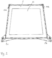
- a tread plate cassette can be provided in the area of the tread surface for inserting a tread plate, the tread plate in the inserted position being arranged above and parallel to the tread surface in the position of use.
- the tread plate cassette is preferably connected to the tread or stair step body, in particular to the tread surface, for example by screwing.
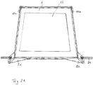
- the tread plate cassette can have at least two and at most three profiles with a U-shaped cross section and a base, such a profile being arranged on one edge of the four edges of the base and a further edge without fixing means for fixing the tread plate in the tread plate cassette.
- the fixing means can have at least one bendable tab which is arranged on the further edge of the bottom of the tread plate cassette or on the edge of the tread surface such that in a first position the at least a tab allows the tread plate to be inserted into the tread plate cassette and the tread plate is fixed within the tread plate cassette in a second position of the at least one tab bent relative to the first position.
- the tread plate can be made of wood, (artificial or natural) stone or plastic, or a mix of materials, depending on the visual requirements.
- the invention also relates to a step or stair system, in particular a floor-based staircase, consisting of a plurality of step or stair step arrangements described above.
- connecting means can be provided, by means of which a plurality of step or stair step arrangements can be connected to one another.
- the connecting means can have at least one connecting profile, of which, viewed in the position of use, at least one first engaging element on a first side and one facing away from the first side second side protrudes at least a second engagement element, wherein the first engagement element engages in a through opening of a first step or step arrangement and the second engagement element engages in a through opening of a second step or step arrangement different from the first step or step arrangement, whereby the first step or stair step arrangement and the second step or stair step arrangement are connected to one another in particular essentially without a viewing gap.
- first engagement element and / or the second engagement element can also be hook-shaped.
- the multiple step or stair step arrangements can then, for example, be arranged laterally and also offset with respect to the vertical level on the slope surface in such a way that their order of the step sequence corresponds to a person climbing the slope.
- the multiple tread arrangements can be arranged in a row one behind the other on the slope surface so that they are in alignment with one another stand.
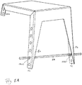
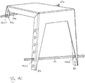
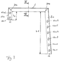
- FIG. 4 Illustrations of a preferred embodiment of a step or stair step arrangement 2 with a step or stair step body 1 for free laying on an inclined slope surface 4 are shown.
- the slope surface 4 takes, for example, a first slope angle ⁇ with respect to a horizontal surface and consists here, for example, of relatively soft soil, so that narrow bodies can easily penetrate the slope surface 4 under pressure.
- the tread or stair step body 1 has a tread 6 provided for entering by, for example, only one foot of a person, as well as here, for example, two front foot parts 8a, 8b, which protrude downward from the tread 6 and are spaced apart in the transverse direction, which measure each have a first vertical extension h1 from the tread surface 6 ( Fig. 3 ).
- rear foot parts 10a, 10b in the use position, which also protrude downward from the tread surface 6, which, measured from the tread surface 6, have a second vertical extension h2, the first vertical extension h1 being greater than the second vertical extension h2 ( Fig. 3 ).
- the free ends 12 of the two front foot parts 8a, 8b and the two rear foot parts 10a, 10b are each provided for at least partially penetrating into the slope surface 4 when the tread surface 6 is loaded. Based on the in Fig. 1 shown situation, the tread or stair step body 1 is still unloaded, so that the free ends 12 of the foot parts 8a, 8b or 10a, 10b are still only on the slope surface 4 but have not yet penetrated into it.
- first front foot part 8a of the front foot parts 8a, 8b there are a plurality of first through openings 14a1 to 14a6, each with a different level position, and in a second front foot part 8b of the front foot parts 8a, 8b second, for example each with the first through openings 14a1 to 14a6 in the transverse direction seen through aligned through opening 14b1 to 14b6 each formed, for example, equidistant.
- the first through openings 14a1 to 14a6 and the second through openings 14b1 to 14b6 differ in each case by a different vertical level on the front foot parts 8a, 8b.
- a rod-shaped limiting element 24 for optional lateral and loose insertion into a specific first through opening 14a1, 14a2, 14a3, 14a4, 14a5 or 14a6 and into a specific second through opening 14b1, 14b2, 14b3, 14b4, 14b5 or 14b6, so that the free ends 12 penetrate through the limiting element 24 of the front foot parts 8a, 8b in the slope surface 4 is limited to a vertical level which corresponds to the vertical level of the limiting element 24 used.
- a slope area with a relatively large slope ⁇ according to Fig. 1A , Figure 1C , Fig.
- the limiting element 24 is inserted, for example, through the second through openings 14a2 and 14b2, seen from below, for example in alignment with one another, the ends of the limiting element 24 projecting a little laterally out of the through openings 14a2, 14b2, for example.
- the proportion of the free ends 12 of the front foot parts 8a, 8b which protrude into the slope surface 4 or are inserted therein is relatively small.
- the slope surface 4 penetrate than is predetermined by the respective vertical level of the limiting element 24.
- the limiting element 24 can be used in certain through openings 14a1, 14a2, 14a3, 14a4, 14a5 or 14a6 or 14b1, 14b2, 14b3, 14b4, 14b5 or 14b6 in such a way that the the step surface 2 positioned step surface 2, the step surface 6 is (almost) aligned horizontally and therefore slipping or sliding of a person's foot is prevented when they put their foot on the step surface 6.
- Figure 1B shows a situation in which the limiting element 24, for example, is not as in FIG Fig. 1A is inserted into through-openings 14a2 and 14b2 which are horizontally aligned with one another, but into through-openings 14a4 and 14b2 which are not exactly aligned with one another.
- the limiting element is then in an angular or oblique position with respect to the horizontal, which is not a result of an adaptation to the shape of the slope surface 4.
- Figure 1C shows a situation in which the limiting element 24, for example, in the first front foot part 8a and the second front foot part 8b as in FIG Fig. 1A is inserted into first and second through openings 14a2, 14b2, each with the same level position.
- the two rear foot parts 10a and 10b each have, for example, two second through openings 16a1, 16a2 or 16b1, 16b2, each with a different level, of which a pair 16a1, 16b1 or 16a2, 16b2 are each aligned horizontally with one another.
- a further limiting element 24a is then inserted, for example, through the lowest through openings 16a1 and 16b1.
- the delimiting elements 24, 24a are then in a respective horizontal position.
- Fig. 7 shows, for example, the step or stair step arrangement 2 as it is attached to or in a slope surface 4 which, with respect to a horizontal surface, has a second slope angle ⁇ which is smaller than the first slope angle ⁇ .
- the limiting element 24 is inserted, for example, into the second pair of through openings 14a5 and 14b5 in the two front foot parts 8a, 8b when viewed from above. Then the proportion of the free ends 12 of the front foot parts 8a, 8b, which protrude into the slope surface 4 or are inserted therein, is relatively large.
- certain through openings that are in alignment here, for example, are therefore used for loose insertion of the limiting element 24 is selected so that when the free ends 12 penetrate the slope surface 4 under load, this penetration is limited by the limiting element 24 in such a way that the tread surface 6 is oriented approximately horizontally in order to ensure a safe step.
- the rod-shaped limiting element 24 is loosely inserted into certain through openings 14a2, 14b2 in the front foot parts 8a, 8b depending on the inclination of the slope surface 4. Then the tread or stair step body 1 with the inserted limiting element 24 is positioned on the slope surface 4 such that the two front foot parts 8a, 8b face downhill and the two rear foot parts 10a, 10b face uphill.
- the free ends 12 of the front foot parts 8a, 8b and the rear foot parts 10a, 10b are pressed into the slope surface 4 with the foot, for example by part of the weight of the person who is resting on the tread 6, until this enters the through openings 14a2 , 14b2 inserted limiting element 24 rests on the slope surface 4 and thereby further penetration of the ends 12 of the front foot parts 8a, 8b into the slope surface 4 is prevented.
- the rod-shaped limiting element 24 and the through openings 14a, 14b can preferably each have a circular cross section. Any cross-section of the rod-shaped delimitation element 24 and the through openings 14a, 14b is conceivable, in particular also a square or rectangular cross-section. Furthermore, the rod-shaped limiting element 24 is formed here, for example, by a rod of reinforced concrete reinforcement.
- the surface of the step surface 6 intended to be entered can be provided with a non-slip pad 26.
- a non-slip pad 26 can in particular consist of a glued-on film with non-slip properties.
- the tread surface 6 can also have through holes 19 with serrated wheels, the tines protruding from the tread surface 6 and then also representing an anti-slip device ( Fig. 1 ).
- an even better adjustment of the orientation or inclination of the step surface 6 of the step or stair step body 1 can be achieved by third through openings 16a1, 16a2 in a first rear foot part 10a of the rear foot parts 10a, 10b and in a second rear foot part 10b rear foot parts 10a, 10b fourth, through openings 16b1, 16b2, which are aligned with the third through openings, for example in the transverse direction, are formed, the third through openings 16a1, 16a2 and the fourth through openings 16b1, 16b2 being distinguished by a different vertical level on the rear foot parts 10a, 10b differentiate.
- the further delimiting element 24a can then be inserted, for example, through the lowest through openings 16a1 and 16b1. As a result, the delimiting elements 24, 24a are then in a respective horizontal position.
- the depth of penetration of their free ends 12 into the slope surface 4 can be limited and thereby the step surface 6 depending on the inclination of the slope surface 4 in the use position of the step or Stair arrangement 2 ideally be aligned horizontally.
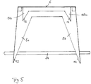
- step or stair step body 1 is formed, as here, by a one-piece sheet steel part in which the front foot parts 8a, 8b and the rear foot parts 10a, 10b are bent from the step surface 6 are, as in particular based on 1 to 5 is easy to imagine.
- the rear foot parts 10a, 10b and the front foot parts 8a, 8b each preferably have an L-shaped cross section.
- a web part 28a, 28b is also laterally folded from the step or stair step body 1, which abuts the front foot parts 8a, 8b and the rear foot parts 10a, 10b in a miter 30a, 30b, 30c, 30d. Then, when the tread surface 6 is loaded, the two front foot parts 8a, 8b and the two rear foot parts 10a, 10b can each be supported on the lateral web parts via the miters 30a, 30b, 30c, 30d.
- the tread surface 6 preferably has a planar extent such that only one foot of a person can occur there.
- the tread 6 can also have a larger width in the manner of a step in the transverse direction, so that, for example, a person with both feet can also step on the tread 6 at the same time.
- the invention also relates to a step or stair system, in particular a floor or slope-bound staircase consisting of a plurality of step or stair step arrangements 2 described above, which are attached to the slope surface 4 in such a way that the slope surface 4 can be walked on as a whole.
- the plurality of tread or stair step arrangements 2 can then, for example, laterally and also with respect to the vertical level on the slope surface 4 can be arranged offset such that their arrangement corresponds to the order in which a person steps up the slope surface 4.
- the plurality of steps or steps 2 can be arranged on the slope 4 in the manner of steps in one Row must be arranged one behind the other so that they are in alignment with each other.
- a locally or continuously curved course of the floor-bound or slope-bound staircase can also be provided, depending on in which the individual step or stair step arrangements 2 are arranged relative to one another on the slope surface 4.
- a tread plate cassette 18, for example made of sheet steel, can be fastened on the tread surface 6 for inserting a tread plate 20, for example by screwing, the tread plate 20 being arranged in the inserted position above and parallel to the tread surface 6.
- the tread plate cassette 18, which is made, for example, in one piece from sheet steel, can have a rectangular or square cross section and, for example, have three adjoining profiles 22a, 22b, 22c each with a U-shaped cross section and a base 25 on the edge ( Fig. 9 ), wherein such a profile 22 is arranged on one edge of the bottom 25 and the fourth edge is provided without such a profile, but has fixing means 23 for fixing the tread plate 20 inserted into the profiles 22a to 22c in the tread plate cassette 18 .
- the fixing means can have bendable (sheet metal) tabs 23 arranged on the fourth edge of the bottom 25 of the tread plate cassette 18 such that the tread plate 20 can be inserted into the tread plate cassette 18 in a first position of the tab, such as Fig. 8 and Fig. 9 show, and in a second, compared to the first position here, for example, upwardly bent position of the tabs 23, the tread plate 20 is fixed within the tread plate cassette 18.
- the tabs 23 can in turn be made in one piece with the tread plate cassette 18 from sheet steel.
- the tread plate 20 can be made of wood, stone or plastic, for example, in order to produce a desired visual impression.
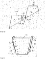
- releasable connecting means can be provided in particular, by means of which a plurality of step or stair step arrangements 2a, 2b can be connected to one another, as in FIG 10 and 11 emerges.
- the connecting means can be formed, for example, by a trapezoidal connecting profile 32, of which, seen in the position of use, first engagement elements, for example in the form of first hooks 34, and second engagement elements, for example in the form of second hooks 36, on a second side pointing away from the first side stick out ( Fig. 11 ).
- connection profile 32 is provided for each of the front and rear foot parts 8a, 10a and 8b, 10b, the first hooks 34 of the then two connection profiles 32, for example, in through openings of the rear foot parts 10a, 10b of a first step or stair step arrangement 2a and the second hooks 36 in through openings of the front foot parts 8a, 8b of a second step or step arrangement 2a different from the first step or step arrangement 2a Intervene in step arrangement 2b.
- the trapezoidal connection profile 32 here, for example, is preferably designed such that the first step or stair step arrangement 2a and the second step or stair step arrangement 2b are connected to one another in particular essentially without a viewing gap.
- the hooks 34, 36 of the connecting profile 32 are then disengaged from the through openings of the foot parts 8a, 8b or 10a, 10b in order to release the step or stair step arrangements 2a, 2b.
Landscapes
- Engineering & Computer Science (AREA)
- Architecture (AREA)
- Civil Engineering (AREA)
- Structural Engineering (AREA)
- Mechanical Engineering (AREA)
- Steps, Ramps, And Handrails (AREA)
- Tires In General (AREA)
Claims (16)
- Dispositif de marchepied ou de marche d'escalier (2) pour la pose libre sur une surface inclinée (4) qui présente au moins un corps de marchepied ou de marche d'escalier (1) aveca) une surface de marche (6) prévue pour être accessible par au moins un pied d'une personne ainsi qu'avecb) au moins deux parties de pied (8a, 8b) antérieures en position d'utilisation, qui font saillie de la surface de marche (6) vers le bas et qui sont espacées l'une de l'autre dans le sens transversal, qui présentent chacune une première extension verticale (h1), ceci étant mesuré à partir de la surface de marche (6), cependant que les extrémités libres (12) d'au moins les parties de pied antérieures (8a, 8b) sont prévues pour la pénétration au moins partielle dans la surface inclinée (4),c) au moins une partie de pied (10a, 10b) postérieure en position d'utilisation qui fait saillie de la surface de marche (6) vers le bas, qui présente une seconde extension verticale (h2), ceci étant mesuré à partir de la surface de marche (6), cependant qued) la première extension verticale (h1) est plus grande que la seconde extension verticale (h2), cependant quee) dans une première partie de pied antérieure (8a) des parties de pied antérieures (8a, 8b) plusieurs premières ouvertures de passage (14a) sont configurées qui sont placées chacune à un niveau différent et dans une seconde partie de pied antérieure (8b) des parties de pied antérieures (8a, 8b) plusieurs secondes ouvertures de passage (14b) placées chacune à un niveau différent,
caractérisé en cef) qu'au moins un élément de délimitation en forme de tige (24) est prévu pour l'insertion lâche au choix dans une première ouverture de passage déterminée (14a) des plusieurs premières ouvertures de passage (14a) et dans une seconde ouverture de passage déterminée (14b) des plusieurs secondes ouvertures de passage (14b) de telle manière que, grâce à l'élément de délimitation (24) mis en place dans la première ouverture de passage déterminée (14a) et la seconde ouverture de passage déterminée (14b), une pénétration des au moins deux parties de pied antérieures (8a, 8b) dans la surface inclinée (4) est limitée à un niveau qui correspond au niveau de l'élément de délimitation (24), cependant queg) l'élément de délimitation en forme de tige (24) fait saillie et est en porte-à-faux de chaque côté latéralement en sortant en partie hors des ouvertures de passage (14a, 14b). - Procédé pour la pose libre d'un dispositif de marchepied ou de marche d'escalier (2) selon la revendication 1 sur une surface inclinée (4), caractérisé par au moins les étapes de procédé suivantes :a) insertion lâche de l'élément de délimitation en forme de tige (24) dans la première ouverture de passage déterminée (14a) et dans la seconde ouverture de passage déterminée (14b) en fonction de l'inclinaison de la surface inclinée (4) de telle manière que l'élément de délimitation en forme de tige (24) fasse saillie et soit en porte-à-faux de chaque côté latéralement en sortant en partie hors des ouvertures de passage (14a, 14b),b) positionnement du corps de marchepied ou de marche d'escalier (1) sur la surface inclinée (4) de telle manière que les au moins deux parties de pied antérieures (8a, 8b) sont tournées vers le bas de la surface inclinée et la au moins une partie de pied postérieure (10a, 10b) est tournée vers le haut de la surface inclinée,c) enfoncement des extrémités libres (12) au moins des parties de pied antérieures (8a, 8b) dans la surface inclinée (4) jusqu'à ce que l'élément de délimitation (24) mis en place dans la première ouverture de passage déterminée (14a) et dans la seconde ouverture de passage déterminée (14b) repose sur la surface inclinée (4) et qu'une pénétration supplémentaire des extrémités libres (12) au moins des parties de pied antérieures (8a, 8b) dans la surface inclinée (4) soit ainsi empêchée.
- Dispositif de marchepied ou de marche d'escalier (2) pour la pose libre sur une surface inclinée (4) qui présente au moins un corps de marchepied ou de marche d'escalier (1) aveca) une surface de marche (6) prévue pour être accessible par au moins un pied d'une personne ainsi qu'avecb) au moins une partie de pied (8a, 8b) antérieure en position d'utilisation, qui fait saillie de la surface de marche (6) vers le bas et qui présente une première extension verticale (h1), ceci étant mesuré à partir de la surface de marche (6),c) au moins deux parties de pied (10a, 10b) postérieures en position d'utilisation qui font saillie de la surface de marche (6) vers le bas et qui sont espacées l'une de l'autre dans le sens transversal, qui présentent une seconde extension verticale (h2), ceci étant mesuré à partir de la surface de marche (6), cependant que les extrémités libres (12) d'au moins les parties de pied postérieures (10a, 10b) sont prévues pour la pénétration au moins partielle dans la surface inclinée (4), cependant qued) la première extension verticale (h1) est plus grande que la seconde extension verticale (h2),
caractérisé en ce quee) plusieurs troisièmes ouvertures de passage placées chacune à un niveau différent sont configurées dans une première partie de pied postérieure (10a) des parties de pied postérieures (10a, 10b) et plusieurs quatrièmes ouvertures de passage placées chacune à un niveau différent sont configurées dans une seconde partie de pied postérieure (10b) des parties de pied postérieures (10a, 10b) etf) qu'au moins un élément de délimitation en forme de tige (24) est prévu pour l'insertion lâche au choix dans une troisième ouverture de passage des plusieurs troisièmes ouvertures de passage et dans une quatrième ouverture de passage des plusieurs quatrièmes ouvertures de passage de telle manière que, grâce à l'élément de délimitation (24) mis en place dans la troisième ouverture de passage déterminée et dans la quatrième ouverture de passage déterminée, une pénétration des extrémités libres (12) des au moins deux parties de pied postérieures (10a, 10b) dans la surface inclinée (4) est limitée à un niveau qui correspond au niveau de l'élément de délimitation (24). - Procédé pour la pose libre d'un dispositif de marchepied ou de marche d'escalier (2) selon la revendication 3 sur une surface inclinée (4), caractérisé par au moins les étapes de procédé suivantes :a) insertion lâche de l'élément de délimitation en forme de tige (24) dans la troisième ouverture de passage déterminée et dans la quatrième ouverture de passage déterminée (14b) en fonction de l'inclinaison de la surface inclinée (4),b) positionnement du corps de marchepied ou de marche d'escalier (1) sur la surface inclinée (4) de telle manière que la au moins une partie de pied antérieure (8a, 8b) est tournée vers le bas de la surface inclinée et les au moins deux parties de pied postérieure (10a, 10b) sont tournées vers le haut de la surface inclinée,c) enfoncement des extrémités libres (12) au moins des parties de pied postérieures (10a, 10b) dans la surface inclinée (4) jusqu'à ce que l'élément de délimitation (24) mis en place dans la troisième ouverture de passage déterminée et dans la quatrième ouverture de passage déterminée repose sur la surface inclinée (4) et qu'une pénétration supplémentaire des extrémités libres (12) au moins des parties de pied postérieures (10a, 10b) dans la surface inclinée (4) soit ainsi empêchée.
- Dispositif de marchepied ou de marche d'escalier (2) pour la pose libre sur une surface inclinée (4) qui présente au moins un corps de marchepied ou de marche d'escalier (1) aveca) une surface de marche (6) prévue pour être accessible par au moins un pied d'une personne ainsi qu'avecb) au moins deux parties de pied (8a, 8b) antérieures en position d'utilisation, qui font saillie de la surface de marche (6) vers le bas, qui présentent une première extension verticale (h1), ceci étant mesuré à partir de la surface de marche (6), cependant que les extrémités libres (12) des parties de pied antérieures (8a, 8b) sont prévues pour la pénétration au moins partielle dans la surface inclinée (4),c) au moins deux parties de pied (10a, 10b) postérieures en position d'utilisation qui font saillie de la surface de marche (6) vers le bas et qui sont espacées l'une de l'autre dans le sens transversal, qui présentent chacune une seconde extension verticale (h2), ceci étant mesuré à partir de la surface de marche (6), cependant que les extrémités libres (12) d'au moins les parties de pied postérieures (10a, 10b) sont prévues pour l'insertion au moins partielle dans la surface inclinée (4), cependant qued) la première extension verticale (h1) est plus grande que la seconde extension verticale (h2),
caractérisé en cee) qu'au moins plusieurs cinquièmes ouvertures de passage, placées chacune à un niveau différent, sont configurées au moins sur un côté du corps de marchepied ou de marche d'escalier (1) sur une partie de pied postérieure (10a ou 10b) des parties de pied postérieures (10a, 10b) placée sur ce même côté et que plusieurs sixièmes ouvertures de passage, placées chacune à un niveau différent, sont configurées sur une partie de pied antérieure (8a ou 8b) des parties de pied antérieures (8a, 8b) placée sur ce même côté etf) qu'au moins un élément de délimitation en forme de tige (24) est prévu pour l'insertion lâche au choix dans une cinquième ouverture de passage déterminée des plusieurs ouvertures de passage et dans une sixième ouverture de passage déterminée des plusieurs sixièmes ouvertures de passage de telle manière que, grâce à l'élément de délimitation (24) mis en place dans la cinquième ouverture de passage déterminée et dans la sixième ouverture de passage déterminée, une pénétration de l'extrémité libre (12) de la au moins une partie de pied antérieure (8a ou 8b) et de l'extrémité libre (12) de la au moins une partie de pied postérieure (10a ou 10b) dans la surface inclinée (4) est limitée à un niveau qui correspond au niveau de l'élément de délimitation (24). - Procédé pour la pose libre d'un dispositif de marchepied ou de marche d'escalier (2) selon la revendication 5 sur une surface inclinée (4), caractérisé par au moins les étapes de procédé suivantes :a) insertion lâche de l'élément de délimitation en forme de tige (24) dans la cinquième ouverture de passage déterminée et dans la sixième ouverture de passage déterminée en fonction de l'inclinaison de la surface inclinée (4),b) positionnement du corps de marchepied ou de marche d'escalier (1) sur la surface inclinée (4) de telle manière que les au moins deux parties de pied antérieures (8a, 8b) sont tournées vers le bas de la surface inclinée et que les au moins deux parties de pied postérieures (10a, 10b) sont tournées vers le haut de la surface inclinée,c) enfoncement de l'extrémité libre (12) au moins de la partie de pied antérieure (8a, 8b) placée sur un côté du corps de marchepied ou de marche d'escalier (1) et de l'extrémité libre (12) d'au moins la partie de pied postérieure (10a ou 10b) placée sur un côté du corps de marchepied ou de marche d'escalier (1) dans la surface inclinée (4) jusqu'à ce que l'élément de délimitation (24) mis en place dans la cinquième ouverture de passage déterminée et dans la sixième ouverture de passage déterminée repose sur la surface inclinée (4) et qu'une pénétration supplémentaire de l'extrémité libre (12) d'au moins la partie de pied antérieure (8a ou 8b) placée sur l'un des côtés du corps de marchepied ou de marche d'escalier (1) et de l'extrémité libre (12) d'au moins la partie de pied postérieure (10a ou 10b) placée sur l'un des côtés du corps de marchepied ou de marche d'escalier (1) dans la surface inclinée (4) soit ainsi empêchée.
- Dispositif de marchepied ou de marche d'escalier (2) pour la pose libre sur une surface inclinée (4) selon au moins l'une des revendications 1, 3 ou 5.
- Dispositif de marchepied ou de marche d'escalier (2) selon l'une des revendications 1, 3, 5 ou 7, caractérisé en ce que l'élément de délimitation en forme de tige (24) et les ouvertures de passage (14a, 14b) présentent chacune une section circulaire ou que l'élément de délimitation en forme de tige (24) présente une section circulaire et les ouvertures de passage (14a, 14b) chacune une section en forme de trou oblong.
- Dispositif de marchepied ou de marche d'escalier (2) selon la revendication 8, caractérisé en ce que l'élément de délimitation en forme de tige (24) est formé par une tige d'une armature pour béton armé.
- Dispositif de marchepied ou de marche d'escalier (2) selon l'une des revendications 1, 3, 5 ou 7 à 9, caractérisé en ce que le corps de marchepied ou de marche d'escalier (1) contient une partie en tôle d'acier en une pièce ou est formée par une pièce de ce type pour laquelle au moins une partie de pied antérieure (8a, 8b) et au moins une partie de pied postérieure (10a, 10b) sont coudées à partir de la surface de marche (6).
- Dispositif de marchepied ou de marche d'escalier (2) selon l'une des revendications 1, 3, 5 ou 7 à 10, caractérisé en ce qu'au moins une partie de pied postérieure (10a, 10b) et au moins une partie de pied antérieure (8a, 8b) présentent chacune une section en forme de L.
- Dispositif de marchepied ou de marche d'escalier (2) selon l'une des revendications 1, 3, 5 ou 7 à 11, caractérisé en ce qu'en position d'utilisation, ceci étant vu à partir du corps de marchepied ou de marche d'escalier (1), une barrette (28a, 28b) est coudée respectivement latéralement, barrette qui rencontre en onglet (30a, 30b, 30c, 30d) respectivement une partie de pied antérieure (8a, 8b) et une partie de pied postérieure (10a, 10b).
- Dispositif de marchepied ou de marche d'escalier (2) selon l'une des revendications 1, 3, 5 ou 7 à 12, caractérisé en ce qu'une cassette de plaque de marchepied (18) est prévue dans la zone de la surface de marche (6) pour insérer une plaque de marche (20), la plaque de marche (20) étant placée, dans l'état inséré en position d'utilisation, au-dessus et parallèlement à la surface de marche (6).
- Dispositif de marchepied ou de marche d'escalier (2) selon la revendication 13, caractérisé en ce que la cassette de marchepied (18) présente au moins deux et au maximum trois profilés (22a à 22c) avec une section en forme de U et un fond (25), cependant qu'un tel profilé (22a à 22c) est placé sur chacun des bords du fond (25) et qu'un autre bord réalisé sans profilé présente des moyens de fixation (23) pour fixer la plaque de marche (20) dans la cassette de marchepied (18).
- Dispositif de marchepied ou de marche d'escalier (2) selon la revendication 14, caractérisé en ce que les moyens de fixation (23) présentent au moins une languette placée sur le bord du fond (25) de la cassette de marchepied (18) ou sur le bord de la surface de marche (6) qui peut être courbée de telle manière que dans une première position de la au moins une languette une insertion de la plaque de marche (20) dans la cassette de marchepied (18) est possible et que dans une seconde position, recourbée par rapport à la première position de la au moins une languette, la plaque de marche (20) est fixée à l'intérieur de la cassette de marchepied (18).
- Système de marchepied ou de marche d'escalier, en particulier escalier lié au sol, constitué par plusieurs dispositifs de marchepied ou de marche d'escalier (2) selon au moins l'une des revendications 1, 3, 5 ou 7 à 15 qui sont reliés l'un à l'autre par des moyens de liaison en particulier amovibles ou qui ne sont pas reliés l'un à l'autre.
Applications Claiming Priority (1)
| Application Number | Priority Date | Filing Date | Title |
|---|---|---|---|
| DE202017005022.6U DE202017005022U1 (de) | 2017-09-27 | 2017-09-27 | Trittstufenanordnung für Hangflächen mit unterschiedlicher Neigung |
Publications (2)
| Publication Number | Publication Date |
|---|---|
| EP3461966A1 EP3461966A1 (fr) | 2019-04-03 |
| EP3461966B1 true EP3461966B1 (fr) | 2020-07-08 |
Family
ID=60579159
Family Applications (1)
| Application Number | Title | Priority Date | Filing Date |
|---|---|---|---|
| EP18196760.5A Active EP3461966B1 (fr) | 2017-09-27 | 2018-09-26 | Dispositif de marches ou de marches d'escalier pour surfaces suspendues à inclinaison différente |
Country Status (2)
| Country | Link |
|---|---|
| EP (1) | EP3461966B1 (fr) |
| DE (1) | DE202017005022U1 (fr) |
Families Citing this family (2)
| Publication number | Priority date | Publication date | Assignee | Title |
|---|---|---|---|---|
| AT522982B1 (de) | 2019-10-11 | 2021-06-15 | Franz Buerscher Dipl Ing | Stützmodul für eine Stufe eines Fußweges auf nicht verbautem Untergrund |
| AT524857B1 (de) * | 2021-08-21 | 2022-10-15 | Standvorrichtung |
Family Cites Families (5)
| Publication number | Priority date | Publication date | Assignee | Title |
|---|---|---|---|---|
| US4520897A (en) * | 1984-05-14 | 1985-06-04 | Gebo George B | Portable steps |
| DE4239690C2 (de) * | 1992-11-26 | 2000-04-20 | Ursula Wychgram | Trittflächenelement |
| CH690501A5 (de) | 1995-07-10 | 2000-09-29 | Roland Scheuchzer | Hilfsvorrichtung zum Arbeiten in geneigtem Gelände. |
| US7162760B2 (en) * | 2003-06-19 | 2007-01-16 | Schweitzer Kathleen M | Methods and apparatus for a step mounting system |
| DE202014100052U1 (de) * | 2013-12-10 | 2014-12-11 | Mts Metallbau Thomas Schneider Gmbh | Trittstufe |
-
2017
- 2017-09-27 DE DE202017005022.6U patent/DE202017005022U1/de active Active
-
2018
- 2018-09-26 EP EP18196760.5A patent/EP3461966B1/fr active Active
Non-Patent Citations (1)
| Title |
|---|
| None * |
Also Published As
| Publication number | Publication date |
|---|---|
| DE202017005022U1 (de) | 2017-11-22 |
| EP3461966A1 (fr) | 2019-04-03 |
Similar Documents
| Publication | Publication Date | Title |
|---|---|---|
| DE102014101322B4 (de) | Abdeckrost | |
| EP1893827B1 (fr) | Escalier d'échafaudage | |
| WO2010046175A2 (fr) | Tiroir et outil pour assujettir le fond d'un tiroir | |
| DE102007010073B4 (de) | Verbindungssystem für Rinnenunterteile | |
| EP1493880B1 (fr) | Cadre de rebord pour planchers | |
| EP0802287B1 (fr) | Grille de drainage réglable en hauteur | |
| WO2009010495A2 (fr) | Élément de transport pour un dispositif de transport et procédé et dispositif pour contrôler des baguettes d'éléments de transport | |
| EP3461966B1 (fr) | Dispositif de marches ou de marches d'escalier pour surfaces suspendues à inclinaison différente | |
| EP3596297A1 (fr) | Système d'échelles pour l'étayage de fouilles | |
| DE102008005813B4 (de) | Vertikalrahmen | |
| DE202008003126U1 (de) | Vorrichtung zur Sicherung von mindestens zwei Gerüstbelagbohlen | |
| DE102007052773B4 (de) | Gerüstbelagbohle | |
| DE102016124988A1 (de) | Beschlag für das Verlegen von Terrassendielen | |
| EP3354818B1 (fr) | Dispositif de compensation en longueur pour échafaudages | |
| DE4418905A1 (de) | Laufboden für Gerüste | |
| AT522982B1 (de) | Stützmodul für eine Stufe eines Fußweges auf nicht verbautem Untergrund | |
| CH673859A5 (fr) | ||
| EP2096235A1 (fr) | Garde-corps à console frontale | |
| DE202009002980U1 (de) | Flexible Treppenvorrichtung | |
| DE202024106910U1 (de) | Als Bockleiter und als Anlegeleiter verwendbare Leiter | |
| DE102014011946B3 (de) | Enddielenhaltevorrichtung für eine Dielenanordnung | |
| DE3447645C2 (fr) | ||
| DE102005051966A1 (de) | Selbstverbindendes Bühnenpodest sowie Bühne und abgestufte Bühne | |
| DE102014011947B3 (de) | Enddielenhaltevorrichtung für eine Dielenanordnung | |
| DE7119038U (de) | Schwellenboden Fertigtafel |
Legal Events
| Date | Code | Title | Description |
|---|---|---|---|
| PUAI | Public reference made under article 153(3) epc to a published international application that has entered the european phase |
Free format text: ORIGINAL CODE: 0009012 |
|
| STAA | Information on the status of an ep patent application or granted ep patent |
Free format text: STATUS: THE APPLICATION HAS BEEN PUBLISHED |
|
| AK | Designated contracting states |
Kind code of ref document: A1 Designated state(s): AL AT BE BG CH CY CZ DE DK EE ES FI FR GB GR HR HU IE IS IT LI LT LU LV MC MK MT NL NO PL PT RO RS SE SI SK SM TR |
|
| AX | Request for extension of the european patent |
Extension state: BA ME |
|
| STAA | Information on the status of an ep patent application or granted ep patent |
Free format text: STATUS: REQUEST FOR EXAMINATION WAS MADE |
|
| 17P | Request for examination filed |
Effective date: 20191004 |
|
| RBV | Designated contracting states (corrected) |
Designated state(s): AL AT BE BG CH CY CZ DE DK EE ES FI FR GB GR HR HU IE IS IT LI LT LU LV MC MK MT NL NO PL PT RO RS SE SI SK SM TR |
|
| GRAP | Despatch of communication of intention to grant a patent |
Free format text: ORIGINAL CODE: EPIDOSNIGR1 |
|
| STAA | Information on the status of an ep patent application or granted ep patent |
Free format text: STATUS: GRANT OF PATENT IS INTENDED |
|
| INTG | Intention to grant announced |
Effective date: 20200224 |
|
| GRAS | Grant fee paid |
Free format text: ORIGINAL CODE: EPIDOSNIGR3 |
|
| GRAA | (expected) grant |
Free format text: ORIGINAL CODE: 0009210 |
|
| STAA | Information on the status of an ep patent application or granted ep patent |
Free format text: STATUS: THE PATENT HAS BEEN GRANTED |
|
| AK | Designated contracting states |
Kind code of ref document: B1 Designated state(s): AL AT BE BG CH CY CZ DE DK EE ES FI FR GB GR HR HU IE IS IT LI LT LU LV MC MK MT NL NO PL PT RO RS SE SI SK SM TR |
|
| REG | Reference to a national code |
Ref country code: CH Ref legal event code: EP Ref country code: AT Ref legal event code: REF Ref document number: 1288585 Country of ref document: AT Kind code of ref document: T Effective date: 20200715 |
|
| REG | Reference to a national code |
Ref country code: DE Ref legal event code: R096 Ref document number: 502018001850 Country of ref document: DE |
|
| REG | Reference to a national code |
Ref country code: CH Ref legal event code: NV Representative=s name: VALIPAT S.A. C/O BOVARD SA NEUCHATEL, CH |
|
| REG | Reference to a national code |
Ref country code: IE Ref legal event code: FG4D Free format text: LANGUAGE OF EP DOCUMENT: GERMAN |
|
| REG | Reference to a national code |
Ref country code: LT Ref legal event code: MG4D |
|
| REG | Reference to a national code |
Ref country code: NL Ref legal event code: MP Effective date: 20200708 |
|
| PG25 | Lapsed in a contracting state [announced via postgrant information from national office to epo] |
Ref country code: FI Free format text: LAPSE BECAUSE OF FAILURE TO SUBMIT A TRANSLATION OF THE DESCRIPTION OR TO PAY THE FEE WITHIN THE PRESCRIBED TIME-LIMIT Effective date: 20200708 Ref country code: LT Free format text: LAPSE BECAUSE OF FAILURE TO SUBMIT A TRANSLATION OF THE DESCRIPTION OR TO PAY THE FEE WITHIN THE PRESCRIBED TIME-LIMIT Effective date: 20200708 Ref country code: PT Free format text: LAPSE BECAUSE OF FAILURE TO SUBMIT A TRANSLATION OF THE DESCRIPTION OR TO PAY THE FEE WITHIN THE PRESCRIBED TIME-LIMIT Effective date: 20201109 Ref country code: GR Free format text: LAPSE BECAUSE OF FAILURE TO SUBMIT A TRANSLATION OF THE DESCRIPTION OR TO PAY THE FEE WITHIN THE PRESCRIBED TIME-LIMIT Effective date: 20201009 Ref country code: NO Free format text: LAPSE BECAUSE OF FAILURE TO SUBMIT A TRANSLATION OF THE DESCRIPTION OR TO PAY THE FEE WITHIN THE PRESCRIBED TIME-LIMIT Effective date: 20201008 Ref country code: ES Free format text: LAPSE BECAUSE OF FAILURE TO SUBMIT A TRANSLATION OF THE DESCRIPTION OR TO PAY THE FEE WITHIN THE PRESCRIBED TIME-LIMIT Effective date: 20200708 Ref country code: BG Free format text: LAPSE BECAUSE OF FAILURE TO SUBMIT A TRANSLATION OF THE DESCRIPTION OR TO PAY THE FEE WITHIN THE PRESCRIBED TIME-LIMIT Effective date: 20201008 Ref country code: SE Free format text: LAPSE BECAUSE OF FAILURE TO SUBMIT A TRANSLATION OF THE DESCRIPTION OR TO PAY THE FEE WITHIN THE PRESCRIBED TIME-LIMIT Effective date: 20200708 Ref country code: HR Free format text: LAPSE BECAUSE OF FAILURE TO SUBMIT A TRANSLATION OF THE DESCRIPTION OR TO PAY THE FEE WITHIN THE PRESCRIBED TIME-LIMIT Effective date: 20200708 |
|
| PG25 | Lapsed in a contracting state [announced via postgrant information from national office to epo] |
Ref country code: PL Free format text: LAPSE BECAUSE OF FAILURE TO SUBMIT A TRANSLATION OF THE DESCRIPTION OR TO PAY THE FEE WITHIN THE PRESCRIBED TIME-LIMIT Effective date: 20200708 Ref country code: RS Free format text: LAPSE BECAUSE OF FAILURE TO SUBMIT A TRANSLATION OF THE DESCRIPTION OR TO PAY THE FEE WITHIN THE PRESCRIBED TIME-LIMIT Effective date: 20200708 Ref country code: LV Free format text: LAPSE BECAUSE OF FAILURE TO SUBMIT A TRANSLATION OF THE DESCRIPTION OR TO PAY THE FEE WITHIN THE PRESCRIBED TIME-LIMIT Effective date: 20200708 Ref country code: IS Free format text: LAPSE BECAUSE OF FAILURE TO SUBMIT A TRANSLATION OF THE DESCRIPTION OR TO PAY THE FEE WITHIN THE PRESCRIBED TIME-LIMIT Effective date: 20201108 |
|
| PG25 | Lapsed in a contracting state [announced via postgrant information from national office to epo] |
Ref country code: NL Free format text: LAPSE BECAUSE OF FAILURE TO SUBMIT A TRANSLATION OF THE DESCRIPTION OR TO PAY THE FEE WITHIN THE PRESCRIBED TIME-LIMIT Effective date: 20200708 |
|
| REG | Reference to a national code |
Ref country code: DE Ref legal event code: R097 Ref document number: 502018001850 Country of ref document: DE |
|
| PG25 | Lapsed in a contracting state [announced via postgrant information from national office to epo] |
Ref country code: EE Free format text: LAPSE BECAUSE OF FAILURE TO SUBMIT A TRANSLATION OF THE DESCRIPTION OR TO PAY THE FEE WITHIN THE PRESCRIBED TIME-LIMIT Effective date: 20200708 Ref country code: DK Free format text: LAPSE BECAUSE OF FAILURE TO SUBMIT A TRANSLATION OF THE DESCRIPTION OR TO PAY THE FEE WITHIN THE PRESCRIBED TIME-LIMIT Effective date: 20200708 Ref country code: CZ Free format text: LAPSE BECAUSE OF FAILURE TO SUBMIT A TRANSLATION OF THE DESCRIPTION OR TO PAY THE FEE WITHIN THE PRESCRIBED TIME-LIMIT Effective date: 20200708 Ref country code: RO Free format text: LAPSE BECAUSE OF FAILURE TO SUBMIT A TRANSLATION OF THE DESCRIPTION OR TO PAY THE FEE WITHIN THE PRESCRIBED TIME-LIMIT Effective date: 20200708 Ref country code: SM Free format text: LAPSE BECAUSE OF FAILURE TO SUBMIT A TRANSLATION OF THE DESCRIPTION OR TO PAY THE FEE WITHIN THE PRESCRIBED TIME-LIMIT Effective date: 20200708 |
|
| PLBE | No opposition filed within time limit |
Free format text: ORIGINAL CODE: 0009261 |
|
| STAA | Information on the status of an ep patent application or granted ep patent |
Free format text: STATUS: NO OPPOSITION FILED WITHIN TIME LIMIT |
|
| PG25 | Lapsed in a contracting state [announced via postgrant information from national office to epo] |
Ref country code: AL Free format text: LAPSE BECAUSE OF FAILURE TO SUBMIT A TRANSLATION OF THE DESCRIPTION OR TO PAY THE FEE WITHIN THE PRESCRIBED TIME-LIMIT Effective date: 20200708 |
|
| 26N | No opposition filed |
Effective date: 20210409 |
|
| REG | Reference to a national code |
Ref country code: BE Ref legal event code: MM Effective date: 20200930 |
|
| PG25 | Lapsed in a contracting state [announced via postgrant information from national office to epo] |
Ref country code: LU Free format text: LAPSE BECAUSE OF NON-PAYMENT OF DUE FEES Effective date: 20200926 Ref country code: SK Free format text: LAPSE BECAUSE OF FAILURE TO SUBMIT A TRANSLATION OF THE DESCRIPTION OR TO PAY THE FEE WITHIN THE PRESCRIBED TIME-LIMIT Effective date: 20200708 |
|
| PG25 | Lapsed in a contracting state [announced via postgrant information from national office to epo] |
Ref country code: BE Free format text: LAPSE BECAUSE OF NON-PAYMENT OF DUE FEES Effective date: 20200930 Ref country code: IE Free format text: LAPSE BECAUSE OF NON-PAYMENT OF DUE FEES Effective date: 20200926 Ref country code: SI Free format text: LAPSE BECAUSE OF FAILURE TO SUBMIT A TRANSLATION OF THE DESCRIPTION OR TO PAY THE FEE WITHIN THE PRESCRIBED TIME-LIMIT Effective date: 20200708 |
|
| PG25 | Lapsed in a contracting state [announced via postgrant information from national office to epo] |
Ref country code: TR Free format text: LAPSE BECAUSE OF FAILURE TO SUBMIT A TRANSLATION OF THE DESCRIPTION OR TO PAY THE FEE WITHIN THE PRESCRIBED TIME-LIMIT Effective date: 20200708 Ref country code: MT Free format text: LAPSE BECAUSE OF FAILURE TO SUBMIT A TRANSLATION OF THE DESCRIPTION OR TO PAY THE FEE WITHIN THE PRESCRIBED TIME-LIMIT Effective date: 20200708 Ref country code: CY Free format text: LAPSE BECAUSE OF FAILURE TO SUBMIT A TRANSLATION OF THE DESCRIPTION OR TO PAY THE FEE WITHIN THE PRESCRIBED TIME-LIMIT Effective date: 20200708 |
|
| PG25 | Lapsed in a contracting state [announced via postgrant information from national office to epo] |
Ref country code: MK Free format text: LAPSE BECAUSE OF FAILURE TO SUBMIT A TRANSLATION OF THE DESCRIPTION OR TO PAY THE FEE WITHIN THE PRESCRIBED TIME-LIMIT Effective date: 20200708 Ref country code: MC Free format text: LAPSE BECAUSE OF FAILURE TO SUBMIT A TRANSLATION OF THE DESCRIPTION OR TO PAY THE FEE WITHIN THE PRESCRIBED TIME-LIMIT Effective date: 20200708 |
|
| REG | Reference to a national code |
Ref country code: CH Ref legal event code: U11 Free format text: ST27 STATUS EVENT CODE: U-0-0-U10-U11 (AS PROVIDED BY THE NATIONAL OFFICE) Effective date: 20251001 |
|
| PGFP | Annual fee paid to national office [announced via postgrant information from national office to epo] |
Ref country code: DE Payment date: 20250917 Year of fee payment: 8 |
|
| PGFP | Annual fee paid to national office [announced via postgrant information from national office to epo] |
Ref country code: GB Payment date: 20250923 Year of fee payment: 8 |
|
| PGFP | Annual fee paid to national office [announced via postgrant information from national office to epo] |
Ref country code: AT Payment date: 20250918 Year of fee payment: 8 Ref country code: FR Payment date: 20250922 Year of fee payment: 8 |
|
| PGFP | Annual fee paid to national office [announced via postgrant information from national office to epo] |
Ref country code: IT Payment date: 20250930 Year of fee payment: 8 |
|
| PGFP | Annual fee paid to national office [announced via postgrant information from national office to epo] |
Ref country code: CH Payment date: 20251001 Year of fee payment: 8 |