EP3461992A1 - Compresseur de type ouvert - Google Patents
Compresseur de type ouvert Download PDFInfo
- Publication number
- EP3461992A1 EP3461992A1 EP18196657.3A EP18196657A EP3461992A1 EP 3461992 A1 EP3461992 A1 EP 3461992A1 EP 18196657 A EP18196657 A EP 18196657A EP 3461992 A1 EP3461992 A1 EP 3461992A1
- Authority
- EP
- European Patent Office
- Prior art keywords
- driving shaft
- main body
- compressor
- lip part
- circumferential surface
- Prior art date
- Legal status (The legal status is an assumption and is not a legal conclusion. Google has not performed a legal analysis and makes no representation as to the accuracy of the status listed.)
- Withdrawn
Links
- 239000000314 lubricant Substances 0.000 claims abstract description 19
- 239000012530 fluid Substances 0.000 claims abstract description 16
- 238000005461 lubrication Methods 0.000 claims description 24
- 230000006835 compression Effects 0.000 description 11
- 238000007906 compression Methods 0.000 description 11
- KAKZBPTYRLMSJV-UHFFFAOYSA-N Butadiene Chemical compound C=CC=C KAKZBPTYRLMSJV-UHFFFAOYSA-N 0.000 description 2
- 238000005299 abrasion Methods 0.000 description 2
- 238000007599 discharging Methods 0.000 description 2
- 238000012423 maintenance Methods 0.000 description 2
- 238000012986 modification Methods 0.000 description 2
- 230000004048 modification Effects 0.000 description 2
- 229920001343 polytetrafluoroethylene Polymers 0.000 description 2
- 239000004810 polytetrafluoroethylene Substances 0.000 description 2
- 239000003507 refrigerant Substances 0.000 description 2
- 230000000903 blocking effect Effects 0.000 description 1
- 230000009977 dual effect Effects 0.000 description 1
- 230000001050 lubricating effect Effects 0.000 description 1
- 239000010687 lubricating oil Substances 0.000 description 1
- 239000000463 material Substances 0.000 description 1
- 238000000034 method Methods 0.000 description 1
- 239000003595 mist Substances 0.000 description 1
- -1 polytetrafluoroethylene Polymers 0.000 description 1
- 239000011347 resin Substances 0.000 description 1
- 229920005989 resin Polymers 0.000 description 1
- 238000007789 sealing Methods 0.000 description 1
Images


Classifications
-
- F—MECHANICAL ENGINEERING; LIGHTING; HEATING; WEAPONS; BLASTING
- F04—POSITIVE - DISPLACEMENT MACHINES FOR LIQUIDS; PUMPS FOR LIQUIDS OR ELASTIC FLUIDS
- F04C—ROTARY-PISTON, OR OSCILLATING-PISTON, POSITIVE-DISPLACEMENT MACHINES FOR LIQUIDS; ROTARY-PISTON, OR OSCILLATING-PISTON, POSITIVE-DISPLACEMENT PUMPS
- F04C27/00—Sealing arrangements in rotary-piston pumps specially adapted for elastic fluids
- F04C27/008—Sealing arrangements in rotary-piston pumps specially adapted for elastic fluids for other than working fluid, i.e. the sealing arrangements are not between working chambers of the machine
- F04C27/009—Shaft sealings specially adapted for pumps
-
- F—MECHANICAL ENGINEERING; LIGHTING; HEATING; WEAPONS; BLASTING
- F01—MACHINES OR ENGINES IN GENERAL; ENGINE PLANTS IN GENERAL; STEAM ENGINES
- F01C—ROTARY-PISTON OR OSCILLATING-PISTON MACHINES OR ENGINES
- F01C19/00—Sealing arrangements in rotary-piston machines or engines
- F01C19/005—Structure and composition of sealing elements such as sealing strips, sealing rings and the like; Coating of these elements
-
- F—MECHANICAL ENGINEERING; LIGHTING; HEATING; WEAPONS; BLASTING
- F04—POSITIVE - DISPLACEMENT MACHINES FOR LIQUIDS; PUMPS FOR LIQUIDS OR ELASTIC FLUIDS
- F04D—NON-POSITIVE-DISPLACEMENT PUMPS
- F04D29/00—Details, component parts, or accessories
- F04D29/08—Sealings
- F04D29/10—Shaft sealings
- F04D29/102—Shaft sealings especially adapted for elastic fluid pumps
- F04D29/104—Shaft sealings especially adapted for elastic fluid pumps the sealing fluid being other than the working fluid or being the working fluid treated
-
- F—MECHANICAL ENGINEERING; LIGHTING; HEATING; WEAPONS; BLASTING
- F04—POSITIVE - DISPLACEMENT MACHINES FOR LIQUIDS; PUMPS FOR LIQUIDS OR ELASTIC FLUIDS
- F04C—ROTARY-PISTON, OR OSCILLATING-PISTON, POSITIVE-DISPLACEMENT MACHINES FOR LIQUIDS; ROTARY-PISTON, OR OSCILLATING-PISTON, POSITIVE-DISPLACEMENT PUMPS
- F04C18/00—Rotary-piston pumps specially adapted for elastic fluids
- F04C18/02—Rotary-piston pumps specially adapted for elastic fluids of arcuate-engagement type, i.e. with circular translatory movement of co-operating members, each member having the same number of teeth or tooth-equivalents
- F04C18/0207—Rotary-piston pumps specially adapted for elastic fluids of arcuate-engagement type, i.e. with circular translatory movement of co-operating members, each member having the same number of teeth or tooth-equivalents both members having co-operating elements in spiral form
- F04C18/0215—Rotary-piston pumps specially adapted for elastic fluids of arcuate-engagement type, i.e. with circular translatory movement of co-operating members, each member having the same number of teeth or tooth-equivalents both members having co-operating elements in spiral form where only one member is moving
Definitions
- the present invention relates to an open type compressor.
- a machine called an open type compressor is known as a type of compressor.
- an open type compressor In an open type compressor, one end of a driving shaft that is rotatably supported inside a housing projects outside the housing, and a driving force from outside is applied to the one end. For this reason, a differential pressure occurs between the inside and outside of the housing along a driving shaft.
- a seal part is provided on an outer circumferential surface of the driving shaft (e.g., see Patent Literature 1 below).
- a lip seal is adopted as the seal part.
- a lubricant included in a fluid circulating in the housing is fed to the lip seal via a lubrication hole and a lubricating groove in a mist form. Thereby, abrasion of the lip seal is reduced.
- the lip seal generally adopts a dual structure.
- the lip seal has a first lip formed of rubber, and a second lip formed of a resin.
- Patent Literature 1 Japanese Unexamined Patent Application, First Publication No. 2016-156310
- the lubrication hole for the lubricant is only provided in the first lip side. For this reason, the lubricant does not sufficiently spread to the second lip side, and abrasion caused by poor lubrication occurs at the second lip. Especially, when the inside of the compressor has a negative pressure according to operating conditions, or when a suction pressure is low and a circulation amount of the lubricant is small, lubrication to the second lip is obstructed, and a likelihood of the poor lubrication is raised.
- the present invention is directed to providing an open type compressor capable of being more stably operated.
- an open type compressor includes: a compressor main body configured to have a driving shaft rotated about an axis and driven to compress a fluid in association with the rotation of the driving shaft; and a seal part configured to come into contact with an outer circumferential surface of the driving shaft and to seal leakage of the fluid from the compressor main body.
- the seal part has a first lip part provided close to the compressor main body in a direction of the axis, and a second lip part provided across the first lip part on a side opposite to the compressor main body in the direction of the axis.
- a feed hole is formed in the outer circumferential surface of the driving shaft, and feeds a lubricant to the outer circumferential surface at a position opposite to the compressor main body on the basis of the first lip part.
- the lubricant can also be spread to the second lip part in addition to the first lip part. Thereby, lubrication can be sufficiently performed between the driving shaft and the seal part.
- the feed hole may be formed in the outer circumferential surface of the driving shaft at a position opposite to the compressor main body on the basis of the second lip part.
- the apparatus can be easily designed and manufactured.
- a plurality of feed holes may be formed in the outer circumferential surface of the driving shaft at intervals in a circumferential direction of the axis.
- the plurality of feed holes may be formed at intervals in the circumferential direction of the axis, lubrication can be sufficiently performed between the outer circumferential surface of the driving shaft and the seal part over the whole region in the circumferential direction.
- the feed hole may communicate with a lubrication hole formed in an end of the driving shaft which is opposite to the compressor main body.
- the lubricant can be easily fed from the outside through the lubrication hole formed in the end of the driving shaft. Thereby, lubrication is possible without disassembling the entire compressor, and maintenance can be easily performed.
- the open type compressor may further include a lid mounted during an operation of the compressor main body and configured to block the lubrication hole.
- the outer circumferential surface of the driving shaft can be kept smooth. Thereby, the driving shaft is smoothly rotated, and the open type compressor can be stably operated.
- an open type scroll compressor (an open type compressor) 1 includes a housing 2, a front housing 3, a compressor main body 1A, and a seal part 9.
- the housing 2 has a cylindrical shape that extends in a direction of an axis X.
- a front housing 3 is mounted in an opening 2a formed on one side of the housing 2 by blocking the opening 2a.
- the front housing 3 is mounted on the housing 2, and thereby a sealed space is formed in the housing 2.
- the compressor main body 1A is housed in the sealed space.
- a suction port 25 that introduces a fluid (a refrigerant gas) into the sealed space and a discharge port 24 that discharges the fluid compressed by the compressor main body 1A from the sealed space to the outside are formed in an outer circumferential surface of the housing 2.
- the compressor main body 1A has a columnar driving shaft 6 that extends along the axis X and a scroll compression section 5 that is coupled to the driving shaft 6.
- the driving shaft 6 is rotatably supported by the front housing 3 via a main bearing 7 and a sub-bearing 8.
- One end of the driving shaft 6 protrudes from the front housing 3 to the outside via the seal part 9.
- a pulley 11 that is rotatably installed on an outer circumferential portion of the front housing 3 via a bearing 10 is coupled to the one end of the driving shaft 6 via an electromagnetic clutch 12. Power that drives the pulley 11 via the electromagnetic clutch 12 is transmitted from the outside to the driving shaft 6, and the driving shaft 6 is rotated about the axis X.
- a crank pin 13 that is eccentric in a radial direction of the axis X is integrally provided on the other end of the driving shaft 6.
- a orbiting scroll 16 of the scroll compression section 5 (to be described below) is coupled to the other end of the driving shaft 6 via the crank pin 13.
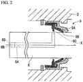
- a flow passage 6A for feeding a lubricant to the seal part 9 is formed inside the driving shaft 6.
- the flow passage 6A extends along the axis X.
- a lubrication hole 6B that opens into the end of the driving shaft 6 is formed close to one end of the flow passage 6A.
- the lubrication hole 6B is formed in the end of the driving shaft 6 which is opposite to the compressor main body 1A.
- a feed hole 6C that opens into an outer circumferential surface of the driving shaft 6 is formed close to the other end of the flow passage 6A.
- only one feed hole 6C is formed in the outer circumferential surface of the driving shaft 6, is orthogonal to the lubrication hole 6B and extends in a radial direction.
- the feed hole 6C may extend to be inclined with respect to the radial direction, or may extend to be curved.
- the lubrication hole 6B is blocked by a lid 6D.
- the lid 6D is removed.
- a set screw is suitably used as a specific example of the lid 6D.
- a set screw having reverse threads formed in a direction opposite to a rotational direction of the driving shaft 6 be used as the lid 6D.
- the lid 6D is not limited to the set screw, and may be a simple bolt or cap.
- the scroll compression section 5 is driven by the driving shaft 6, thereby compressing the fluid introduced from the suction port 25 and discharging the compressed fluid from the discharge port 24.
- a fixed scroll 15 and the orbiting scroll 16 are engaged with a phase shifted by 180°, and thereby a compression chamber 17 is formed between the fixed scroll 15 and the orbiting scroll 16.
- the fixed scroll 15 and the orbiting scroll 16 have end plates 15A and 16A and spiral laps 15B and 16B provided on the end plates 15A and 16A.
- a discharge port 18 for discharging the compressed fluid is formed in the center of the fixed scroll 15.
- the fixed scroll 15 is fixed to the bottom of the housing 2 via bolts 19.
- the orbiting scroll 16 is coupled to the crank pin 13 of the driving shaft 6 via a driven crank mechanism 14 and is supported to enable revolution and gyration relative to the fixed scroll 15.
- An O-ring 21 is mounted on an outer circumferential portion of the end plate 15A of the fixed scroll 15.
- the O-ring 21 comes into close contact with an inner circumferential surface of the housing 2, and thereby an internal space of the housing 2 is partitioned into a discharge chamber 22 and a suction chamber 23.
- the discharge chamber 22 communicates with a discharge port 18.
- the fluid (the compressed refrigerant gas) fed from the compression chamber 17 flows into the discharge chamber 22.
- the suction chamber 23 communicates with a suction port 25 formed in the housing 2.
- a low-pressure fluid introduced through the suction port 25 is suctioned into the compression chamber 17 via the suction chamber 23.
- the main bearing 7 supports the driving shaft 6 on the axis X.
- the main bearing 7 has an inner ring 7a press-fitted onto the driving shaft 6 and an outer ring 7b press-fitted into the front housing 3.
- the main bearing 7 is disposed closer to the scroll compression section 5 than the sub-bearing 8 (to be described below).
- the main bearing 7 is a ball bearing having a larger outer diameter than the sub-bearing 8.
- the sub-bearing 8 has an inner ring 8a press-fitted onto the driving shaft 6 and an outer ring 8b press-fitted into the front housing 3.
- the sub-bearing 8 is disposed closer to the scroll compression section 5 than the seal part 9.
- the sub-bearing 8 is a needle bearing having a smaller outer diameter than the main bearing 7.
- the seal part 9 is in contact with the outer circumferential surface of the driving shaft 6, thereby sealing leakage of the fluid from the compressor main body 1A.
- the seal part 9 is mounted on the inner circumferential surface of the front housing 3.
- the seal part 9 is a lip seal.
- the seal part 9 has a first lip part 9A that is provided relatively close to the compressor main body 1A in the direction of the axis X, and a second lip part 9B that is provided adjacent to the first lip part 9A.
- the second lip part 9B is provided across the first lip part 9A on a side opposite to the compressor main body 1A in the direction of the axis X.
- the first lip part is formed of rubber composed of butadiene or the like.
- PTFE polytetrafluoroethylene
- the first lip part 9A is formed in an annular shape having a cross section that obliquely extends from an outer side to an inner side of the driving shaft 6 in the radial direction as it goes from one side to the other side in the direction of the axis X. An end of the other side of the first lip part 9A is in contact with the outer circumferential surface of the driving shaft 6.
- the second lip part 9B is formed in an annular shape having a cross section that obliquely extends from an outer side to an inner side of the axis X in the radial direction as it goes from one side to the other side in the direction of the axis X. An end of the other side of the second lip part 9B is in contact with the outer circumferential surface of the driving shaft 6.
- the aforementioned feed hole 6C opens into one side (an atmosphere side) relative to the second lip part 9B in the direction of the axis X. That is, the feed hole 6C is provided on the outer circumferential surface of the driving shaft 6 at a position opposite to the compressor main body 1A on the basis of the first lip part 9A. In other words, the feed hole 6C is formed at a position opposite to the compressor main body 1A on the basis of the second lip part 9B.
- the lid 6D In feeding the lubricant, the lid 6D is demounted from the feed hole 6B formed in the end of the driving shaft 6 first. Afterward, liquid lubricant is injected into the flow passage 6A through the lubrication hole 6B by a dropper. The lubricant circulating through the flow passage 6A reaches the outer circumferential surface of the driving shaft 6 via the feed hole 6C. After the lubrication is completed, the lid 6D is mounted in the feed hole 6C again. Afterward, the open type compressor 1 is operated, and thereby the lubricant is spread on the outer circumferential surface of the driving shaft 6. Lubrication is performed between the seal part 9 and the driving shaft 6.
- the lubricant can also be spread to the second lip part 9B in addition to the first lip part 9A. Thereby, lubrication can be sufficiently performed between the driving shaft 6 and the seal part 9.
- the feed hole 6C is formed at a position opposite to the compressor main body 1A on the basis of the second lip part 9B, the lubricant can be sufficiently fed to the second lip part 9B.
- the apparatus can be easily designed and manufactured.
- the lubricant can be easily fed from the outside through the lubrication hole 6B formed in the end of the driving shaft 6. Thereby, maintenance of the apparatus can be easily performed.
- the embodiment of the present invention has been described.
- the above constitution is an example, and various modifications or alternations can be performed on the above constitution without departing the gist of the present invention.
- the number of feed holes 6C is not limited to one, and may be two or more.
- a plurality of feed holes 6C may be formed in the outer circumferential surface of the driving shaft 6 at intervals in a circumferential direction of the axis X. According to this constitution, lubrication can be sufficiently performed between the outer circumferential surface of the driving shaft 6 and the seal part 9 over the whole region in the circumferential direction.
- the open type compressor as described in this application enables to obtain a stable operation.
Landscapes
- Engineering & Computer Science (AREA)
- Mechanical Engineering (AREA)
- General Engineering & Computer Science (AREA)
- Applications Or Details Of Rotary Compressors (AREA)
- Sealing With Elastic Sealing Lips (AREA)
- Sealing Devices (AREA)
Applications Claiming Priority (1)
| Application Number | Priority Date | Filing Date | Title |
|---|---|---|---|
| JP2017188237A JP6961438B2 (ja) | 2017-09-28 | 2017-09-28 | 開放型圧縮機 |
Publications (1)
| Publication Number | Publication Date |
|---|---|
| EP3461992A1 true EP3461992A1 (fr) | 2019-04-03 |
Family
ID=63683799
Family Applications (1)
| Application Number | Title | Priority Date | Filing Date |
|---|---|---|---|
| EP18196657.3A Withdrawn EP3461992A1 (fr) | 2017-09-28 | 2018-09-25 | Compresseur de type ouvert |
Country Status (2)
| Country | Link |
|---|---|
| EP (1) | EP3461992A1 (fr) |
| JP (1) | JP6961438B2 (fr) |
Citations (4)
| Publication number | Priority date | Publication date | Assignee | Title |
|---|---|---|---|---|
| DE202004019718U1 (de) * | 2004-12-21 | 2005-03-03 | Burgmann Industries Gmbh & Co. Kg | Anordnung aus einer Welle mit darauf montierter Gleitringdichtung |
| GB2440542A (en) * | 2006-07-31 | 2008-02-06 | Boc Group Plc | Vacuum pump gearbox purge gas arrangement |
| WO2014106247A1 (fr) * | 2012-12-31 | 2014-07-03 | Thermo King Corporation | Dispositif et procédé pour prolonger la durée de vie d'un joint pour arbre tournant pour un compresseur ouvert |
| JP2016156310A (ja) | 2015-02-24 | 2016-09-01 | 三菱重工業株式会社 | 開放型圧縮機 |
Family Cites Families (2)
| Publication number | Priority date | Publication date | Assignee | Title |
|---|---|---|---|---|
| US7178450B1 (en) * | 2005-10-06 | 2007-02-20 | Delphi Technologies, Inc. | Sealing system for a compressor |
| JP2009174376A (ja) * | 2008-01-23 | 2009-08-06 | Valeo Thermal Systems Japan Corp | 圧縮機の軸封構造 |
-
2017
- 2017-09-28 JP JP2017188237A patent/JP6961438B2/ja active Active
-
2018
- 2018-09-25 EP EP18196657.3A patent/EP3461992A1/fr not_active Withdrawn
Patent Citations (4)
| Publication number | Priority date | Publication date | Assignee | Title |
|---|---|---|---|---|
| DE202004019718U1 (de) * | 2004-12-21 | 2005-03-03 | Burgmann Industries Gmbh & Co. Kg | Anordnung aus einer Welle mit darauf montierter Gleitringdichtung |
| GB2440542A (en) * | 2006-07-31 | 2008-02-06 | Boc Group Plc | Vacuum pump gearbox purge gas arrangement |
| WO2014106247A1 (fr) * | 2012-12-31 | 2014-07-03 | Thermo King Corporation | Dispositif et procédé pour prolonger la durée de vie d'un joint pour arbre tournant pour un compresseur ouvert |
| JP2016156310A (ja) | 2015-02-24 | 2016-09-01 | 三菱重工業株式会社 | 開放型圧縮機 |
Also Published As
| Publication number | Publication date |
|---|---|
| JP2019065704A (ja) | 2019-04-25 |
| JP6961438B2 (ja) | 2021-11-05 |
Similar Documents
| Publication | Publication Date | Title |
|---|---|---|
| US8747088B2 (en) | Open drive scroll compressor with lubrication system | |
| US10138887B2 (en) | Scroll compressor | |
| US10100833B2 (en) | Scroll compressor | |
| US10436199B2 (en) | Rotary compressor | |
| US10539139B2 (en) | Compressor | |
| US7281913B2 (en) | Compressor including integrally formed separation tube and seal bolt | |
| TW201736731A (zh) | 無油式螺旋壓縮機 | |
| EP2236828A1 (fr) | Compresseur à spirale | |
| EP3461992A1 (fr) | Compresseur de type ouvert | |
| KR20060051788A (ko) | 압축기 | |
| JP2009062820A (ja) | 密閉形ロータリ圧縮機 | |
| US10082140B2 (en) | Scroll compressor having compression chamber communicating with discharge port via a gap between recessed part formed on front face of movable-side plate and tip of fixed-side lap | |
| EP3315781B1 (fr) | Compresseur de type ouvert | |
| JPH0849681A (ja) | スクロール型圧縮機 | |
| JP2019065706A (ja) | 開放型圧縮機 | |
| JP2001003867A (ja) | 横型圧縮機 | |
| AU2009284906B2 (en) | Scroll fluid machine | |
| EP3992461B1 (fr) | Compresseur à spirale | |
| WO2018030065A1 (fr) | Machine à fluide de type à volute | |
| JP2007085298A (ja) | 圧縮機 | |
| EP3421803B1 (fr) | Compresseur de type ouvert | |
| EP3150855B1 (fr) | Compresseur de type ouvert | |
| EP3447295A1 (fr) | Compresseur de type ouvert | |
| JP2021046811A (ja) | 横置き型スクロール圧縮機 | |
| JP2007182774A (ja) | スクロール型流体機械 |
Legal Events
| Date | Code | Title | Description |
|---|---|---|---|
| PUAI | Public reference made under article 153(3) epc to a published international application that has entered the european phase |
Free format text: ORIGINAL CODE: 0009012 |
|
| STAA | Information on the status of an ep patent application or granted ep patent |
Free format text: STATUS: THE APPLICATION HAS BEEN PUBLISHED |
|
| AK | Designated contracting states |
Kind code of ref document: A1 Designated state(s): AL AT BE BG CH CY CZ DE DK EE ES FI FR GB GR HR HU IE IS IT LI LT LU LV MC MK MT NL NO PL PT RO RS SE SI SK SM TR |
|
| AX | Request for extension of the european patent |
Extension state: BA ME |
|
| STAA | Information on the status of an ep patent application or granted ep patent |
Free format text: STATUS: REQUEST FOR EXAMINATION WAS MADE |
|
| STAA | Information on the status of an ep patent application or granted ep patent |
Free format text: STATUS: EXAMINATION IS IN PROGRESS |
|
| 17P | Request for examination filed |
Effective date: 20190912 |
|
| RBV | Designated contracting states (corrected) |
Designated state(s): AL AT BE BG CH CY CZ DE DK EE ES FI FR GB GR HR HU IE IS IT LI LT LU LV MC MK MT NL NO PL PT RO RS SE SI SK SM TR |
|
| 17Q | First examination report despatched |
Effective date: 20191007 |
|
| STAA | Information on the status of an ep patent application or granted ep patent |
Free format text: STATUS: THE APPLICATION HAS BEEN WITHDRAWN |
|
| 18W | Application withdrawn |
Effective date: 20191122 |