EP3462664A1 - Procédé d'émission et de réception de signal de référence d'informations d'état de canal dans un système de communications sans fil, et appareil à cet effet - Google Patents
Procédé d'émission et de réception de signal de référence d'informations d'état de canal dans un système de communications sans fil, et appareil à cet effet Download PDFInfo
- Publication number
- EP3462664A1 EP3462664A1 EP18811696.6A EP18811696A EP3462664A1 EP 3462664 A1 EP3462664 A1 EP 3462664A1 EP 18811696 A EP18811696 A EP 18811696A EP 3462664 A1 EP3462664 A1 EP 3462664A1
- Authority
- EP
- European Patent Office
- Prior art keywords
- csi
- resource
- resources
- base station
- frequency
- Prior art date
- Legal status (The legal status is an assumption and is not a legal conclusion. Google has not performed a legal analysis and makes no representation as to the accuracy of the status listed.)
- Granted
Links
Images







Classifications
-
- H—ELECTRICITY
- H04—ELECTRIC COMMUNICATION TECHNIQUE
- H04B—TRANSMISSION
- H04B7/00—Radio transmission systems, i.e. using radiation field
- H04B7/02—Diversity systems; Multi-antenna system, i.e. transmission or reception using multiple antennas
- H04B7/04—Diversity systems; Multi-antenna system, i.e. transmission or reception using multiple antennas using two or more spaced independent antennas
- H04B7/0413—MIMO systems
- H04B7/0456—Selection of precoding matrices or codebooks, e.g. using matrices antenna weighting
-
- H—ELECTRICITY
- H04—ELECTRIC COMMUNICATION TECHNIQUE
- H04B—TRANSMISSION
- H04B7/00—Radio transmission systems, i.e. using radiation field
- H04B7/02—Diversity systems; Multi-antenna system, i.e. transmission or reception using multiple antennas
- H04B7/04—Diversity systems; Multi-antenna system, i.e. transmission or reception using multiple antennas using two or more spaced independent antennas
- H04B7/06—Diversity systems; Multi-antenna system, i.e. transmission or reception using multiple antennas using two or more spaced independent antennas at the transmitting station
- H04B7/0613—Diversity systems; Multi-antenna system, i.e. transmission or reception using multiple antennas using two or more spaced independent antennas at the transmitting station using simultaneous transmission
- H04B7/0615—Diversity systems; Multi-antenna system, i.e. transmission or reception using multiple antennas using two or more spaced independent antennas at the transmitting station using simultaneous transmission of weighted versions of same signal
- H04B7/0619—Diversity systems; Multi-antenna system, i.e. transmission or reception using multiple antennas using two or more spaced independent antennas at the transmitting station using simultaneous transmission of weighted versions of same signal using feedback from receiving side
- H04B7/0621—Feedback content
- H04B7/0626—Channel coefficients, e.g. channel state information [CSI]
-
- H—ELECTRICITY
- H04—ELECTRIC COMMUNICATION TECHNIQUE
- H04B—TRANSMISSION
- H04B7/00—Radio transmission systems, i.e. using radiation field
- H04B7/02—Diversity systems; Multi-antenna system, i.e. transmission or reception using multiple antennas
- H04B7/04—Diversity systems; Multi-antenna system, i.e. transmission or reception using multiple antennas using two or more spaced independent antennas
- H04B7/06—Diversity systems; Multi-antenna system, i.e. transmission or reception using multiple antennas using two or more spaced independent antennas at the transmitting station
- H04B7/0686—Hybrid systems, i.e. switching and simultaneous transmission
- H04B7/0695—Hybrid systems, i.e. switching and simultaneous transmission using beam selection
-
- H—ELECTRICITY
- H04—ELECTRIC COMMUNICATION TECHNIQUE
- H04J—MULTIPLEX COMMUNICATION
- H04J13/00—Code division multiplex systems
- H04J13/16—Code allocation
-
- H—ELECTRICITY
- H04—ELECTRIC COMMUNICATION TECHNIQUE
- H04L—TRANSMISSION OF DIGITAL INFORMATION, e.g. TELEGRAPHIC COMMUNICATION
- H04L5/00—Arrangements affording multiple use of the transmission path
- H04L5/0001—Arrangements for dividing the transmission path
- H04L5/0014—Three-dimensional division
- H04L5/0023—Time-frequency-space
-
- H—ELECTRICITY
- H04—ELECTRIC COMMUNICATION TECHNIQUE
- H04L—TRANSMISSION OF DIGITAL INFORMATION, e.g. TELEGRAPHIC COMMUNICATION
- H04L5/00—Arrangements affording multiple use of the transmission path
- H04L5/003—Arrangements for allocating sub-channels of the transmission path
- H04L5/0048—Allocation of pilot signals, i.e. of signals known to the receiver
-
- H—ELECTRICITY
- H04—ELECTRIC COMMUNICATION TECHNIQUE
- H04L—TRANSMISSION OF DIGITAL INFORMATION, e.g. TELEGRAPHIC COMMUNICATION
- H04L5/00—Arrangements affording multiple use of the transmission path
- H04L5/003—Arrangements for allocating sub-channels of the transmission path
- H04L5/0048—Allocation of pilot signals, i.e. of signals known to the receiver
- H04L5/005—Allocation of pilot signals, i.e. of signals known to the receiver of common pilots, i.e. pilots destined for multiple users or terminals
-
- H—ELECTRICITY
- H04—ELECTRIC COMMUNICATION TECHNIQUE
- H04L—TRANSMISSION OF DIGITAL INFORMATION, e.g. TELEGRAPHIC COMMUNICATION
- H04L5/00—Arrangements affording multiple use of the transmission path
- H04L5/003—Arrangements for allocating sub-channels of the transmission path
- H04L5/0053—Allocation of signalling, i.e. of overhead other than pilot signals
-
- H—ELECTRICITY
- H04—ELECTRIC COMMUNICATION TECHNIQUE
- H04L—TRANSMISSION OF DIGITAL INFORMATION, e.g. TELEGRAPHIC COMMUNICATION
- H04L5/00—Arrangements affording multiple use of the transmission path
- H04L5/003—Arrangements for allocating sub-channels of the transmission path
- H04L5/0078—Timing of allocation
- H04L5/0082—Timing of allocation at predetermined intervals
-
- H—ELECTRICITY
- H04—ELECTRIC COMMUNICATION TECHNIQUE
- H04L—TRANSMISSION OF DIGITAL INFORMATION, e.g. TELEGRAPHIC COMMUNICATION
- H04L5/00—Arrangements affording multiple use of the transmission path
- H04L5/0091—Signalling for the administration of the divided path, e.g. signalling of configuration information
- H04L5/0094—Indication of how sub-channels of the path are allocated
-
- H—ELECTRICITY
- H04—ELECTRIC COMMUNICATION TECHNIQUE
- H04W—WIRELESS COMMUNICATION NETWORKS
- H04W24/00—Supervisory, monitoring or testing arrangements
- H04W24/10—Scheduling measurement reports ; Arrangements for measurement reports
-
- H—ELECTRICITY
- H04—ELECTRIC COMMUNICATION TECHNIQUE
- H04W—WIRELESS COMMUNICATION NETWORKS
- H04W76/00—Connection management
- H04W76/20—Manipulation of established connections
- H04W76/27—Transitions between radio resource control [RRC] states
-
- H—ELECTRICITY
- H04—ELECTRIC COMMUNICATION TECHNIQUE
- H04L—TRANSMISSION OF DIGITAL INFORMATION, e.g. TELEGRAPHIC COMMUNICATION
- H04L27/00—Modulated-carrier systems
- H04L27/26—Systems using multi-frequency codes
- H04L27/2601—Multicarrier modulation systems
- H04L27/2602—Signal structure
- H04L27/261—Details of reference signals
-
- H—ELECTRICITY
- H04—ELECTRIC COMMUNICATION TECHNIQUE
- H04W—WIRELESS COMMUNICATION NETWORKS
- H04W72/00—Local resource management
- H04W72/04—Wireless resource allocation
- H04W72/044—Wireless resource allocation based on the type of the allocated resource
- H04W72/0446—Resources in time domain, e.g. slots or frames
Definitions
- the present disclosure relates to a wireless communication system and, more particularly, to a method for transmitting and receiving a channel state information (CSI)-reference signal (RS) and an apparatus supporting the same.
- CSI channel state information
- RS reference signal
- Mobile communication systems have been generally developed to provide voice services while guaranteeing user mobility. Such mobile communication systems have gradually expanded their coverage from voice services through data services up to high-speed data services. However, as current mobile communication systems suffer resource shortages and users demand even higher-speed services, development of more advanced mobile communication systems is needed.
- the requirements of the next-generation mobile communication system may include supporting huge data traffic, a remarkable increase in the transfer rate of each user, the accommodation of a significantly increased number of connection devices, very low end-to-end latency, and high energy efficiency.
- various techniques such as small cell enhancement, dual connectivity, massive multiple input multiple output (MIMO), in-band full duplex, non-orthogonal multiple access (NOMA), supporting super-wide band, and device networking, have been researched.
- the present disclosure is to provide a method of designing a reference signal (RS) (e.g., TRS) to be used for time/frequency tracking.
- RS reference signal
- the present disclosure proposes a method of explicitly or implicitly providing configuration of a TRS.
- the present disclosure provides a method of transmitting and receiving a control state information (CSI)-reference signal (RS) in a wireless communication system.
- CSI control state information
- RS reference signal
- a method performed by a base station includes: configuring control information indicating that an antenna port for all CSI-RS resources included in a CSI-RS resource set is same, wherein the CSI-RS resource set is used for tracking at least one of a time or a frequency; transmitting the configured control information to a user equipment (UE); and transmitting the CSI-RS to the UE through all the CSI-RS resources.
- UE user equipment
- the antenna port may be 1-port
- the UE may be a UE in a radio resource control (RRC) connected state.
- RRC radio resource control
- the CSI-RS may be a periodic CSI-RS.
- all the CSI-RS resources may be configured with a same periodicity.
- all the CSI-RS resources may be configured in a single slot or multiple slots.
- the multiple slots may be consecutive slots.
- symbol locations of all the CSI-RS resources may be different when all the CSI-RS resources are configured in the single slot.
- code division multiplexing may not be applied to all the CSI-RS resources.
- a frequency domain density of each of the CSI-RS resources may be greater than 1.
- the CSI-RS resource set may not be configured both for the tracking and for beam management.
- a CSI-RS resource used for the tracking may be quasi co-located (QCL) with a CSI-RS resource used for CSI acquisition, a CSI-RS resource used for beam management, or an SS/PBCH block (SSB).
- QCL quasi co-located
- SSB SS/PBCH block
- a time domain measurement restriction for the CSI-RS may be set to "OFF".
- linkage between the CSI-RS resource set and a report setting may not be set.
- linkage between the CSI-RS resource set and a specific report setting may be set.
- the specific report setting may be a null reporting setting.
- the method may further include receiving information related to a density of a time domain of the CSI-RS from the UE.
- the time domain may be a single slot or consecutive slots.
- a method for receiving a channel state information (CSI)-reference signal(RS) by a user equipment (UE) in a wireless communication system may include: receiving, from a base station, control information indicating that an antenna port for all CSI-RS resources included in a CSI-RS resource set is same, wherein the CSI-RS resource set is used for tracking at least one of a time or a frequency; receiving, from the base station, the CSI-RS through all the CSI-resources; and tracking at least one of a time or a frequency based on the received CSI-RS.
- CSI channel state information
- a base station which transmits a channel state information (CSI)-reference signal (RS) in a wireless communication system and includes: a radio frequency (RF) module configured to transmit and receive a wireless signal; and a processor functionally connected to the RF module and configured to: configure control information indicating that an antenna port for all CSI-RS resources included in a CSI-RS resource set is same, wherein the CSI-RS resource set is used for tracking at least one of a time or a frequency; transmit the configured control information to a user equipment (UE); and transmit the CSI-RS to the UE through all the CSI-RS resources.
- CSI channel state information
- RS channel state information-reference signal
- the present disclosure newly defines a tracking reference signal (TRS) so as to more precisely perform time/frequency tracking of a user equipment (UE).
- TRS tracking reference signal
- a base station has the meaning of a terminal node of a network over which the base station directly communicates with a terminal.
- a specific operation that is described to be performed by a base station may be performed by an upper node of the base station according to circumstances. That is, it is evident that in a network including a plurality of network nodes including a base station, various operations performed for communication with a terminal may be performed by the base station or other network nodes other than the base station.
- the base station (BS) may be substituted with another term, such as a fixed station, a Node B, an eNB (evolved-NodeB), a base transceiver system (BTS), or an access point (AP).
- the terminal may be fixed or may have mobility and may be substituted with another term, such as user equipment (UE), a mobile station (MS), a user terminal (UT), a mobile subscriber station (MSS), a subscriber station (SS), an advanced mobile station (AMS), a wireless terminal (WT), a machine-type communication (MTC) device, a machine-to-Machine (M2M) device, or a device-to-device (D2D) device.
- UE user equipment
- MS mobile station
- UT user terminal
- MSS mobile subscriber station
- SS subscriber station
- AMS advanced mobile station
- WT wireless terminal
- MTC machine-type communication
- M2M machine-to-Machine
- D2D device-to-device
- downlink means communication from a base station to UE
- uplink means communication from UE to a base station.
- a transmitter may be part of a base station, and a receiver may be part of UE.
- a transmitter may be part of UE, and a receiver may be part of a base station.
- CDMA code division multiple access
- FDMA frequency division multiple access
- TDMA time division multiple access
- OFDMA orthogonal frequency division multiple access
- SC-FDMA single carrier frequency division multiple access
- NOMA non-orthogonal multiple access
- CDMA may be implemented using a radio technology, such as universal terrestrial radio access (UTRA) or CDMA2000.
- TDMA may be implemented using a radio technology, such as global system for mobile communications (GSM)/general packet radio service (GPRS)/enhanced data rates for GSM evolution (EDGE).
- GSM global system for mobile communications
- GPRS general packet radio service
- EDGE enhanced data rates for GSM evolution
- OFDMA may be implemented using a radio technology, such as Institute of electrical and electronics engineers (IEEE) 802.11 (Wi-Fi), IEEE 802.16 (WiMAX), IEEE 802.20, or evolved UTRA (E-UTRA).
- UTRA is part of a universal mobile telecommunications system (UMTS).
- 3rd generation partnership project (3GPP) Long term evolution (LTE) is part of an evolved UMTS (E-UMTS) using evolved UMTS terrestrial radio access (E-UTRA), and it adopts OFDMA in downlink and adopts SC-FDMA in uplink.
- LTE-advanced (LTE-A) is the evolution of 3GPP LTE.
- Embodiments of the present disclosure may be supported by the standard documents disclosed in at least one of IEEE 802, 3GPP, and 3GPP2, that is, radio access systems. That is, steps or portions that belong to the embodiments of the present disclosure and that are not described in order to clearly expose the technical spirit of the present disclosure may be supported by the documents. Furthermore, all terms disclosed in this document may be described by the standard documents.
- 3GPP LTE/LTE-A is chiefly described, but the technical characteristics of the present disclosure are not limited thereto.
- eLTE eNB An eLTE eNB is an evolution of an eNB that supports a connection for an EPC and an NGC.
- gNB A node for supporting NR in addition to a connection with an NGC
- New RAN A radio access network that supports NR or E-UTRA or interacts with an NGC
- Network slice is a network defined by an operator so as to provide a solution optimized for a specific market scenario that requires a specific requirement together with an inter-terminal range.
- a network function is a logical node in a network infra that has a well-defined external interface and a well-defined functional operation.
- NG-C A control plane interface used for NG2 reference point between new RAN and an NGC
- NG-U A user plane interface used for NG3 reference point between new RAN and an NGC
- Non-standalone NR A deployment configuration in which a gNB requires an LTE eNB as an anchor for a control plane connection to an EPC or requires an eLTE eNB as an anchor for a control plane connection to an NGC
- Non-standalone E-UTRA A deployment configuration an eLTE eNB requires a gNB as an anchor for a control plane connection to an NGC.
- User plane gateway A terminal point of NG-U interface
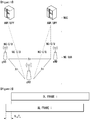
- FIG. 1 is a diagram illustrating an example of an overall structure of a new radio (NR) system to which a method proposed by the present disclosure may be implemented.
- NR new radio
- an NG-RAN is composed of gNBs that provide an NG-RA user plane (new AS sublayer/PDCP/RLC/MAC/PHY) and a control plane (RRC) protocol terminal for a UE (User Equipment).
- NG-RA user plane new AS sublayer/PDCP/RLC/MAC/PHY
- RRC control plane
- the gNBs are connected to each other via an Xn interface.
- the gNBs are also connected to an NGC via an NG interface.
- the gNBs are connected to a Access and Mobility Management Function (AMF) via an N2 interface and a User Plane Function (UPF) via an N3 interface.
- AMF Access and Mobility Management Function
- UPF User Plane Function
- multiple numerologies may be supported.
- the numerologies may be defined by subcarrier spacing and a CP (Cyclic Prefix) overhead. Spacing between the plurality of subcarriers may be derived by scaling basic subcarrier spacing into an integer N (or ⁇ ).
- N or ⁇
- a numerology to be used may be selected independent of a frequency band.
- OFDM Orthogonal Frequency Division Multiplexing
- ⁇ f max 480 ⁇ 10 3
- N f 4096.
- FIG. 2 illustrates a relationship between a UL frame and a DL frame in a wireless communication system to which a method proposed by the present disclosure may be implemented.
- slots are numbered in ascending order of n s ⁇ ⁇ 0 , ... , N subframe slots , ⁇ ⁇ 1 in a subframe, and in ascending order of n s , f ⁇ ⁇ 0 , ... , N frame slots , ⁇ ⁇ 1 in a radio frame.
- One slot is composed of continuous OFDM symbols of N symb , ⁇ and N symb ⁇ is determined depending on a numerology in use and slot configuration.
- the start of slots n s ⁇ in a subframe is temporally aligned with the start of OFDM symbols n s ⁇ N symb ⁇ in the same subframe.
- Not all UEs are able to transmit and receive at the same time, and this means that not all OFDM symbols in a DL slot or an UL slot are available to be used.
- Table 2 shows the number of OFDM symbols per slot for a normal CP in the numerology ⁇
- Table 3 shows the number of OFDM symbols per slot for an extended CP in the numerology ⁇ .
- [Table 2] ⁇ Slot configuration 0 1 N symb ⁇ N frame slots , ⁇ N subframe slots , ⁇ N symb ⁇ N frame slots , ⁇ N subframe slots , ⁇ 0 14 10 1 7 20 2 1 14 20 2 7 40 4 2 14 40 4 7 80 8 3 14 80 8 - - - 4 14 160 16 - - - 5 14 320 32 - - - [Table 3] ⁇ Slot configuration 0 1 N symb ⁇ N frame slots , ⁇ N subframe slots , ⁇ N symb ⁇ N frame slots , ⁇ N subframe slots , ⁇ 0 12 10 1 6 20 2 1 12 20 2 6 40 4 2 12 40 4 6 80 8 3 12 80 8 - - - 4 12 160 16
- an antenna port a resource grid, a resource element, a resource block, a carrier part, etc. may be considered.
- the antenna port is defined such that a channel over which a symbol on one antenna port is transmitted can be inferred from another channel over which a symbol on the same antenna port is transmitted.
- the two antenna ports may be in a QC/QCL (quasi co-located or quasi co-location) relationship.
- the large-scale properties may include at least one of delay spread, Doppler spread, Doppler shift, average gain, and average delay.
- FIG. 3 illustrates an example of a resource grid supported in a wireless communication system to which a method proposed by the present disclosure may be implemented.
- a resource grid is composed of N RB ⁇ N sc RB subcarriers in a frequency domain, each subframe composed of 14 ⁇ 2 ⁇ OFDM symbols, but the present disclosure is not limited thereto.
- a transmitted signal is described by one or more resource grids, composed of N RB ⁇ N sc RB subcarriers, and 2 ⁇ N symb ⁇ OFDM symbols
- N RB ⁇ ⁇ N RB max , ⁇ indicates the maximum transmission bandwidth, and it may change not just between numerologies, but between UL and DL.
- one resource grid may be configured for the numerology ⁇ and an antenna port p.
- Each element of the resource grid for the numerology ⁇ and the antenna port p is indicated as a resource element, and may be uniquely identified by an index pair ( k , l ).
- the index pair ( k , l ) is used.
- l 0 , ... , N symb ⁇ ⁇ 1.
- the resource element ( k , l ) for the numerology ⁇ and the antenna port p corresponds to a complex value a k , l ⁇ p ⁇ .
- the indexes p and ⁇ may be dropped and thereby the complex value may become a k , l ⁇ p or a k, l .
- physical resource blocks may be numbered from 0 to N RB ⁇ ⁇ 1.
- n PRB ⁇ k N sc RB ⁇
- a UE may be configured to receive or transmit the carrier part using only a subset of a resource grid.
- a set of resource blocks which the UE is configured to receive or transmit are numbered from 0 to N URB ⁇ ⁇ 1 in the frequency region.
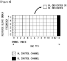
- FIG. 4 is a diagram illustrating an example of a self-contained subframe structure in a wireless communication system to which the present disclosure may be implemented.
- 5G new RAT In order to minimize data transmission latency in a TDD system, 5G new RAT considers a self-contained subframe structure as shown in FIG. 4 .
- a diagonal line area (symbol index 0) represents a UL control area
- a black area (symbol index 13) represents a UL control area.
- a non0shade area may be used for DL data transmission or for UL data transmission.
- This structure is characterized in that DL transmission and UL transmission are performed sequentially in one subframe and therefore transmission of DL data and reception of UL ACK/NACK may be performed in the subframe. In conclusion, it is possible to reduce time for retransmitting data upon occurrence of a data transmission error and thereby minimize a latency of final data transmission.
- a time gap is necessary for a base station or a UE to switch from a transmission mode to a reception mode or to switch from the reception mode to the transmission mode.
- some OFDM symbols at a point in time of switching from DL to UL in the self-contained subframe structure are configured as a guard period (GP).
- a wavelength is short in a Millimeter Wave (mmW) range
- a plurality of antenna elements may be installed in the same size of area. That is, a wavelength in the frequency band 30GHz is 1cm, and thus, 64 (8x8) antenna elements may be installed in two-dimensional arrangement with a 0.5 lambda (that is, a wavelength) in 4 X 4 (4 by 4) cm panel. Therefore, in the mmW range, the coverage may be enhanced or a throughput may be increased by increasing a beamforming (BF) gain with a plurality of antenna elements.
- BF beamforming
- TXRU transceiver unit
- independent beamforming for each frequency resource is possible.
- a method is considered in which a plurality of antenna elements is mapped to one TXRU and a direction of beam is adjusted with an analog phase shifter.
- Such an analog BF method is able to make only one beam direction over the entire frequency band, and there is a disadvantage that frequency-selective BF is not allowed.
- a hybrid BF may be considered which is an intermediate between digital BF and analog BF, and which has B number of TXRU less than Q number of antenna elements.
- B number of TXRU less than Q number of antenna elements.
- beam directions capable of being transmitted at the same time is restricted to be less than B.
- FIG. 5 is an example of a transceiver unit model in a wireless communication system to which the present disclosure may be implemented.
- a TXRU virtualization model represents a relationship between output signals from TXRUs and output signals from antenna elements.
- the TXRU virtualization model may be classified as a TXRU virtualization model option-1: sub-array partition model, as shown in FIG. 5(a) , or as a TXRU virtualization model option-2: full-connection model.
- the antenna elements are divided into multiple antenna element groups, and each TXRU may be connected to one of the multiple antenna element groups. In this case, the antenna elements are connected to only one TXRU.
- signals from multiple TXRUs are combined and transmitted to a single antenna element (or arrangement of antenna elements). That is, this shows a method in which a TXRU is connected to all antenna elements. In this case, the antenna elements are connected to all the TXRUs.
- q represents a transmitted signal vector of antenna elements having M number of co-polarized in one column.
- W represents a wideband TXRU virtualization weight vector, and W represents a phase vector to be multiplied by an analog phase shifter. That is, a direction of analog beamforming is decided by W.
- x represents a signal vector of M_TXRU number of TXRUs.
- mapping of the antenna ports and TXRUs may be performed on the basis of 1-to-1 or 1-to-many.
- TXRU-to-element mapping In FIG. 5 is merely an example, and the present disclosure is not limited thereto and may be equivalently applied even to mapping of TXRUs and antenna elements which can be implemented in a variety of hardware forms.
- CSI Channel State Information
- a UE receives a pilot signal (or a reference signal) for estimating a channel from a base station, calculate channel state information (CSI), and reports the CSI to the base station.
- a pilot signal or a reference signal
- CSI channel state information
- the base station transmits a data signal based on the CSI information fed back from the UE.
- the CSI information fed back from the UE in the LTE system includes channel quality information (CQI), a precoding matrix index (PMI), and a rank indicator (RI).
- CQI channel quality information
- PMI precoding matrix index
- RI rank indicator
- CQI feedback is wireless channel quality information which is provided to the base station for a purpose (link adaptation purpose) of providing a guidance as to which modulation & coding scheme (MCS) to be applied when the base station transmits data.
- MCS modulation & coding scheme
- the UE may feed back a high CQI value and the base station may transmit data by applying a relatively high modulation order and a low channel coding rate.
- the UE may feed back a low CQI value and the base station may transmit data by applying a relatively low modulation order and a high channel coding rate.
- PMI feedback is preferred precoding matrix information which is provided to a base station in order to provide a guidance as to which MIMO precoding scheme is to be applied when the base station has installed multiple antennas.
- a UE estimates a downlink MIMO channel between the base station and the UE from a pilot signal, and recommends, through PMI feedback, which MIMO precoding is desired to be applied by the base station.
- the base station and the UE share a codebook composed of a plurality of precoding matrixes, and each MIMO precoding matrix in the codebook has a unique index.
- the UE minimizes an amount of feedback information thereof.
- a PMI value is not necessarily composed of one index.
- a final 8tx MIMO precoding matrix may be derived only when two indexes (first PMI & second PMI) are combined.
- RI feedback is information on the number of preferred transmission layers, the information which is provided to the base station in order to provide a guidance as to the number of the UE's preferred transmission layers when the base station and the UE have installed multiple antennas to thereby enable multi-layer transmission through spatial multiplexing.
- the RI and the PMI are very closely corelated to each other. It is because the base station is able to know which precoding needs to be applied to which layer depending on the number of transmission layers.
- a PMI codebook may be configured with respect to single layer transmission and then PMI may be defined for each layer and fed back, but this method has a disadvantage that an amount of PMI/RI feedback information increases remarkably in accordance with an increase in the number of transmission layers.
- a PMI codebook is defined depending on the number of transmission layers. That is, for R-layer transmission, N number of Nt x R matrixes are defined (herein, R represents the number of layers, Nt represents the number of transmitter antenna ports, and N represents the size of the codebook).
- a size of a PMI codebook is defined irrespective of the number of transmission layers.
- the number of transmission layers (R) conforms to a rank value of the precoding matrix (Nt x R matrix), and, for this reason, the term "rank indicator(RI)" is used.
- PMI/RI described in the present disclosure is not restricted to mean an index value of a precoding matrix Nt x R and a rank value of the precoding matrix.
- PMI described in the present disclosure indicates information on a preferred MINO precoder from among MIMO precoders capable of being applied by a transmitter, and a form of the precoder is not limited to a linear precoder which is able to be expressed in a matrix form, unlike in the LTE system.
- RI described in the present disclosure means wider than RO in LTE and includes feedback information indicating the number of preferred transmission layers.
- the CSI information may be obtained in all system frequency domains or in some of the frequency domains. In particular, in a broad bandwidth system, it may be useful to obtain CSI information on some frequency domains (e.g., subband) preferred by each UE and then feedback the obtained CSI information.
- some frequency domains e.g., subband
- CSI feedback is performed via an UL channel
- periodic CSI feedback is performed via a physical uplink control channel (PUCCH)
- aperiodic CSI feedback is performed via physical uplink shared channel (PUSCH) which is a UL data channel.
- PUCCH physical uplink control channel
- PUSCH physical uplink shared channel
- the aperiodic CSI feedback means temporarily transmitting a feedback only when a base station needs CSI feedback information, and the base station triggers the CSI feedback via a DL control channel such as a PDCCH/ePDCCH.
- a PUSCH CSI reporting mode which information a UE needs to feedback in response to triggering of CSI feedback is defined as a PUSCH CSI reporting mode, as shown in FIG. 8 , and a PUSCH CSI reporting mode in which the UE needs to operate is informed for the UE in advance via a higher layer message.
- CSI-RS channel state information-reference signal
- RSRP layer 1(L1)-reference signal received power
- a and/or B may be interpreted as the same as “including at least one of A or B”.
- the CSI computation is related to CSI acquisition, and L1-RSRP computation is related to beam management (BM).
- BM beam management
- the CSI indicates all types of information indicative of a quality of a radio channel (or link) formed between a UE and an antenna port.
- FIG. 6 is a flowchart illustrating an example of a CSI-related procedure.
- a terminal receives CSI related configuration information from a base station (e.g., a general node B (gNB)) through a radio resource control (RRC) signaling(S610).
- a base station e.g., a general node B (gNB)
- RRC radio resource control
- the CSI-related configuration information may include at least one of CSI interference management (IM) resource-related information, CSI measurement configuration-related information, CSI resource configuration-related information, CSI-RS resource-related information, or CSI report configuration-related information.
- IM CSI interference management
- the CSIIM resource-related information may include CSI-IM resource information, CSI-IM resource set information, etc..
- the CSI-IM resource set is identified by a CSI-IM resource set ID (identifier), and one resource set includes at least one CSI-IM resource.
- Each CSI-IM resource is identified by a CSI-IM resource ID.
- the CSI resource configuration-related information defines a group including at least one of a non-zero power (NZP) CSI-RS resource set, a CSI-IM resource set, or a CSI-SSB resource set.
- NZP non-zero power
- the CSI resource configuration-related information includes a CSI-RS resource set list
- the CSI-RS resource set list may include at least one of a NZP CSI-RS resource set list, a CSI-IM resource set list, or a CSI-SSB resource set list.
- the CSI resource configuration-related information may be expressed as CSI-REsourceConfig IE.
- the CSI-RS resource set is identified by a CSI-RS resource set ID, and one resource set includes at least one CSI-RS resource.
- Each CSI-RS resource is identified by a CSI-RS resource ID.
- parameters e.g.: the BM-related parameter repetition, and the tracking-related parameter trs-Info indicative of(or indicating) a purpose of a CSI-RS may be set for each NZP CSI-RS resource set.
- Table 4 shows an example of NZP CSI-RS resource set IE.
- -ASN1START -TAG-NZP-CSI-RS-RESOURCESET-START NZP-CSI-RS-ResourceSet SEQUENCE ⁇ nzp-CSI-ResourceSetId NZP-CSI-RS-ResourceSetId, nzp-CSI-RS-Resources SEQUENCE (SIZE (1..maxNrofNZP-CSI-RS-ResourcesPerSet)) OF NZP-CSI-RS-ResourceId, repetition ENUMERATED ⁇ on, off ⁇ aperiodic TriggeringOffset INTEGER(0..4) trs-Info ENUMERATED ⁇ true ⁇ ... ⁇ -TAG-NZP-CSI-RS-RESOURCESET-STOP -ASN1STOP
- the parameter repetition is a parameter indicative of whether to repeatedly transmit the same beam, and indicates whether repetition is set to "ON” or "OFF” for each NZP CSI-RS resource set.
- transmission (Tx) beam used in the present disclosure may be interpreted as the same as a spatial domain transmission filter
- reception (Rx) beam used in the present disclosure may be interpreted as the same as a spatial domain reception filter
- a UE when the parameter repetition in Table 4 is set to "OFF", a UE does not assume that a NZP CSI-RS resource(s) in a resource set is transmitted to the same DL spatial domain transmission filter and the same Nrofports in all symbols.
- the parameter repetition corresponding to a higher layer parameter corresponds to "CSI-RS-ResourceRep" of L1 parameter.
- the CSI report configuration related information includes the parameter reportConfigType indicative of a time domain behavior and the parameter reportQuantity indicative of a CSI-related quantity to be reported.
- the time domain behavior may be periodic, aperiodic, or semi-persistent.
- the CSI report configuration-related information may be represented as CSI-ReportConfig IE, and Table 5 shows an example of the CSI-ReportConfig IE.
- Table 5 SEQUENCE ⁇ reportConfigld CSI-ReportConfigld, carrier ServCellIndex OPTIONAL, - resourcesForChannelMeasurement CSI-ResourceConfigId, csi-IM-ResourcesForInterference CSI-ResourceConfigld OPTIONAL, -- Need R nzp-CSI-RS-ResourcesForInterference CSI-ResourceConfigld OPTIONAL, -- Need R reportConfigType CHOICE ⁇ periodic SEQUENCE ⁇ reportSlotConfig CSI-ReportPeriodicityAndOffset, pucch-CSI-ResourceList SEQUENCE (SIZE (1..maxNrofBWPs
- the UE measures CSI based on configuration information related to the CSI (S620).
- Measuring the CSI may include (1) receiving a CSI-RS by the UE (S621) and (2) computing CSI based on the received CSI-RS (S622).
- a sequence for the CSI-RS is generated by Equation 2, and an initialization value of a pseudo-random sequence C(i) is defined by Equation 3.
- n s , f ⁇ is a slot number within a radio frame
- a pseudo-random sequence generator is initialized with Cint at the start of each OFDM symbol where n s , f ⁇ is the slot number within a radio frame.
- l indicates an OFDM symbol number in a slot
- n ID indicates higher-layer parameter scramblingID
- resource element (RE) mapping of CSI-RS resources of the CSI-RS is performed in time and frequency domains by higher layer parameter CSI-RS-ResourceMapping.
- Table 6 shows an example of CSI-RS-ResourceMapping IE.
- -ASN1START -TAG-CSI-RS-RESOURCEMAPPING-START CSI-RS-ResourceMapping SEQUENCE ⁇ frequencyDomainAllocation CHOICE ⁇ row1 BIT STRING (SIZE (4)), row2 BIT STRING (SIZE (12)), row4 BIT STRING (SIZE (3)), other BIT STRING (SIZE (6)) ⁇ , nrofPorts ENUMERATED ⁇ p1,p2,p4,p8,p12,p16,p24,p32 ⁇ , firstOFDMSymbolInTimeDomain INTEGER (0..13), firstOFDMSymbolInTimeDomain2 INTEGER (2..12) cdm-Type ENUMERATED ⁇ noCDM, fd-CDM2, cdm4-FD2- TD2, cdm8-FD2-TD4 ⁇ , density CHOICE ⁇ dot5 ENUM
- a density (D) indicates a density of CSI-RS resources measured in a RE/port/physical resource block (PRB), and nrofPorts indicates the number of antenna ports.
- the UE reports the measured CSI to the base station (S630).
- a quantity of CSI-ReportConfig in Table 6 is set to "none(or No report)"
- the UE may skip the reporting.
- the UE may report the measured CSI to the base station.
- the case where the quantity is set to "none" is t when an aperiodic TRS is triggered or when repetition is set.
- reporting by the UE is omitted only when repetition is set to "ON".
- a CSI report may indicate any one of “No report”, “SSB Resource Indicator (SSBRI) and L1-RSRP", and “CSI-RS Resource Indicator (CRI) and L1-RSRP”.
- SSBRI SSB Resource Indicator
- CRI CSI-RS Resource Indicator
- a CSI report indicative of "SSBRI and L1-RSRP” or “CRI and L1-RSRP” when repetition is set to “OFF” it may be defined such that, and to transmit a CSI report indicative of "No report”, "SSBRI and L1-RSRP", or “CRI and L1-RSRP” when repetition is "ON”.
- BM Beam management
- NR New Radio
- BM procedures are layer 1(L1)/layer 2(L2) procedures for acquiring and maintaining a set of beams from a base station (e.g. a gNB, TRP, etc.) and/or a terminal (e.g., a UE) to be used for DL and UL transmission/reception, and the BM procedures may include the following procedures and terms.
- FIG. 7 is a conceptual diagram illustrating an example of a beam-related measurement model.
- an SS block (or an SS/PBCH block (SSB)) or a CRI-RS) is used in DL, and an sounding reference signal (SRS) is used in UL.
- SSB SS/PBCH block
- SRS sounding reference signal
- a UE may measure a plurality of beams (at least one beam) in a cell, and the UE may average the measurements (RSRP, RSRQ, SINR, etc.) to derive a cell quality.
- the UE may be configured to consider a sub-set of a detected beam(s).
- Beam measurement-related filtering is performed at two different levels (at the physical layer which induces a beam quality and at the RRC level which induces a cell quality from multiple beams).
- the cell quality may be induced from the beam measurements in the same manner with respect to both of a cell quality of a serving cell (s) and a cell quality of a non-serving cell(s).
- a measurement report includes measurements of X number of best beams.
- the beam measurement may be reported as L1-RSRP.
- K number of beams (gNB beam 1, gNB beam 2, ..., gNB beam k) 710 are configured by the gNB for L3 mobility, and correspond to a measurement of an SS (synchronized signal) block (SSB) or a CSI-RS resource detected by the UE in L1.
- SS synchronized signal
- Layer 1 filtering 720 means inner Layer 1 filtering of inputs measured at point A.
- Beam Consolidation/Selection 730 a beam-specific measurement is consolidated (or integrated) to induce a cell quality.
- Layer 3 filtering 740 for a cell quality means filtering performed on measurements provided at point B.
- the UE evaluates a reporting criterion whenever a new measurement is reported at least at points C and C1.
- D corresponds to measurement report information (message) transmitted on a wireless interface.
- L3 beam filtering 750 filtering is performed on a measurement (a beam-specific measurement) provided at point A1.
- beam selection 760 for beam reporting, X number of measurements provided at point E is selected.
- F indicates beam measurement information included in a measurement report (transmitted) on a wireless interface.
- the BM procedures may be classified into (1) a DL BM procedure using a synchronization signal (SS)/physical broadcast channel (PBCH) Block or a CSI-RS, and (2) a UL BM procedure using an SRS.
- SS synchronization signal
- PBCH physical broadcast channel
- each BM procedure may include Tx beam weeping for determining a Tx beam, and Rx beam sweeping for determining an Rx beam.
- the DL BM procedure may include (1) transmitting a beamformed DL RS eference signals) (e.g., a CSI RS or a SS Block (SSB)) of a base station, and (2) beam reporting by a UE.
- a beamformed DL RS eference signals e.g., a CSI RS or a SS Block (SSB)
- SSB SS Block
- the beam reporting may include a preferred DL RS ID(identifier)(s) and L1-RSRP corresponding thereto.
- the DL RS ID may be a SSB Resource Indicator (SSBRI) or a CSI-RS Resource Indicator (CRI).
- SSBRI SSB Resource Indicator
- CRI CSI-RS Resource Indicator
- FIG. 8 is a diagram illustrating a Tx beam regarding the DL BM procedure.
- an SSB beam and a CSI-RS beam may be used for beam measurement.
- a measurement metric is L1-RSRP for each resource/block.
- An SSB may be used for coarse beam measurement, and a CSI-RS may be used for fine beam measurement.
- the SSB may be used for both Tx beam sweeping and Rx beam sweeping.
- the Rx beam sweeping using the SSB may be performed in a manner in which a UE changes an Rx beam for the same SSBRI across a plurality of SSB burst.
- a single SS burst includes one or more SSBs
- a single SS burst set includes one or more SSB bursts.
- FIG. 9 is a flowchart illustrating an example of the DL BM procedure using SSB.
- Configuration of a beam report using an SSB is performed upon CSI/beam configuration in an RRC connected state (or RRC connected mode).
- BM configuration using an SSB is not defined additionally, and the SSB is set as a CSI-RS resource.
- Table. 7 shows an example of CSI-ResourceConfig IE.
- -- ASN1START -- TAG-CSI-RESOURCECONFIG-START CSI-ResourceConfig :: SEQUENCE ⁇ csi-ResourceConfigld CSI-ResourceConfigld, csi-RS-ResourceSetList CHOICE ⁇ nzp-CSI-RS-SSB SEQUENCE ⁇ nzp-CSI-RS-ResourceSetList SEQUENCE (SIZE (1..maxNrofNZP-CSI-RS- ResourceSetsPerConfig)) OFNZP-CSI-RS-ResourceSetId OPTIONAL, csi-SSB-ResourceSetList SEQUENCE (SIZE (1..maxNrofCSI-SSB- ResourceSetsPerConfig)) OF CSI-SSB-ResourceSetId OPTIONAL ⁇ , csi-IM-ResourceSetList SEQUENCE (SIZE (1..maxNrofCSI
- the parameter csi-SSB-ResourceSetList indicates a list of SSB resources used for beam management and reports in a single resource set.
- the UE receives, from the base station, CSI-ResourceConfig IE including CSI-SSB-ResourceSetList which includes SSB resources used for BM (S910).
- the SSB resource set may be configured as ⁇ SSBx1, SSBx2, SSBx3, SSBx4, ... ⁇ .
- An SSB index may be defined from 0 to 63.
- the UE receives the SSB resources from the base station based on the CSI-SSB-ResourceSetList (S920).
- the UE when CSI-RS reportConfig for SSBRI and L1-RSRP reporting is configured, the UE (beam) reports the best SSBRI and L1-RSRP corresponding thereto to the base station (S930).
- reportQuantity in the CSI-RS reportConfig IE is configured as ssb-Index-RSRP
- the UE reports the best SSBRI and L1-RSRP corresponding thereto to the base station.
- the UE may assume that the CSI-RS and the SSB are quasi co-located with eac other in terms of "QCL-TypeD".
- the QCL Type D may mean that antenna ports are QCL with each other in terms of the spatial Rx parameter.
- the UE receives a plurality of DL antenna ports which are in a QCL Type D relationship with each other, it is possible to apply the same Rx beam.
- the UE does not expect that a CSI-RS is configured in an RE overlapping with a RE of the SSB.
- the UE may assume that at least one CSI-RS resource in NZP-CSI-RS-ResourceSet is transmitted to the same downlink spatial domain transmission filter.
- At least one CSI-RS resource in the NZP-CSI-RS-ResourceSet is transmitted via the same Tx beam.
- At least one CSI-RS resource in the NZP-CSI-RS-ResourceSet may be transmitted via a different OFDM symbol or may be transmitted in a different frequency domain (that is, via FDM).
- the case where the at least one CSI-RS resource is subject to FDM is when the UE is a multi-panel UE.
- repetition is set to "ON" relates to an Rx beam sweeping procedure of the UE.
- the UE does not expect to receive different periodicities at periodicityAndOffset from all CSI-RS resources in the NZP-CSI-RS-Resourceset.
- the UE when the repetition is set to "OFF", the UE does not assume that at least one CSI-RS resource in the NZP-CSI-RS-Resourceset is transmitted to the same downlink spatial domain transmission filter.
- At least one CSI-RS resource in the NZP-CSI-RS-Resourceset is transmitted via a different TX bam.
- the case where the repetition is set to "OFF" relates to a Tx beam sweeping procedure of a base station.
- the parameter repetition may be set only for CSI-RS resource sets that are associated with CSI-ReportConfig having a report of L1 RSRP or "No Report or None".
- the UE may be composed of a port of the same number (1-port or 2-port), which includes higher layer parameter "nrofPorts" for all CSI-RS resources in the NZP-CSI-RS-ResourceSet.
- the CSI-RS is used for beam management.
- the CSI-RS is used for a tracking reference signal (TRS).
- the CSI-RS is used for CSI acquisition.
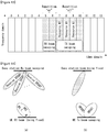
- FIG. 10 is a diagram illustrating an example of a DL BM procedure using a CSI-RS.
- FIG. 10a shows an Rx beam determination (or refinement) procedure of a UE
- FIG. 10b shows a Tx beam determination procedure of a base station.
- FIG. 10a shows the case where the parameter repetition is set to "ON”
- FIG. 10b shows the case where the parameter "repetition” is set as "OFF”.
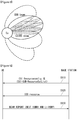
- FIG. 11 is a flowchart illustrating an example of the Rx beam determination procedure of the UE.
- the UE receives, from the base station, NZP CSI-RS resource set IE including higher layer parameter repetition through RRC signaling (S1110).
- the parameter repetition is set to "ON".
- the UE repeatedly receives a resource(s) in a CSI-RS resource set, in which repetition is set to "ON", from a different OFDM symbol through the same Tx beam (or a DL spatial domain transmission filter) (S1120).
- the UE determines its own Rx beam (S1130).
- the UE may omit a CSI report or may transmit a CSI report including CRI/L1-RSRP to the base station (S 1140).
- reportQuantity of CSI report Config may be configured as "No report (or None)" or "CRI and L1-RSRP".
- the UE may omit a CSI report or may report ID information (CRI) of a beam pair-related preferred beam and a quality value thereof (L1-RSRP).
- CRI ID information
- L1-RSRP quality value thereof
- FIG. 12 is a flowchart illustrating an example of the Tx beam determination procedure of the base station.
- a UE receives, from the base station, NZP CSI-RS resource set IE including higher layer parameter repetition through RRC signaling (S1210).
- the parameter repetition is set to "OFF" and relates to a Tx beam sweeping procedure of the base station.
- the UE receives resources in a CSI-RS resource set, in which repetition is set to "OFF", via a different Tx beam (a DL spatial domain transmission filter) (S1220).
- a different Tx beam a DL spatial domain transmission filter
- the UE selects (or determines) the best beam (S1230), and reports ID and quality information (e.g., L1-RSRP) of the selected beam to the base station (S1240).
- ID and quality information e.g., L1-RSRP
- reportQuantity of CSI report Config may be configured as "CRI + L1-RSRP".
- the UE when the CSI-RS is transmitted for BM, the UE reports CSI and L1-RSRP corresponding thereto to the base station.
- FIG. 13 is a diagram illustrating an example of resource allocation in time and frequency domains, which is related to operation of FIG. 10 .
- a UE may receive RRC configuration of a list of a maximum M number of candidate Transmission Configuration Indication (TCI) states at least for the purpose of Quasi Colocation (CQL) indication.
- TCI Transmission Configuration Indication
- CQL Quasi Colocation
- M may be 64.
- Each TCI state may be configured as one RS set.
- each DL RS for a spatial QCL at least in an RS set may refer to at least one of DL RS types such as an SSB, a P-CSI RS, a SP-CSI RS, or a A-CSI RS.
- Initialization/update of ID of DL RS(s) in an RS set used at least for a spatial QCL purpose may be performed at least via explicit signaling.
- Table 8 shows an example of TCI-State IE.
- the TCI-State IE is associated with a quasi co-location (QCL) type corresponding to one or two DL reference signals (RSs).
- QCL quasi co-location
- RSs DL reference signals
- ⁇ QCL-Info :: SEQUENCE ⁇ cell ServCellIndex bwp-Id BWP-Id referenceSignal CHOICE ⁇ csi-rs NZP-CSI-RS-ResourceId, ssb SSB-Index ⁇ , qcl-Type ENUMERATED ⁇ typeA, typeB, typeC, typeD ⁇ , ... ⁇ -- TAG-TCI-STATE-STOP -- ASN1STOP
- the parameter "bwp-id” indicates a BL BWP where a RS is located
- the parameter "cell” indicates a carrier where an RS is located
- the parameter "referencesignal” indicates a reference antenna port(s) which is a quasi colocation source for a corresponding target antenna port(s).
- the target antenna port(s) may be an example of a CSI-RS, a PDCCH DMRS, or a PDSCH DMRS.
- TCI state ID may be indicated in each CORESET configuration.
- DCI state ID may be indicated via DCI.
- An antenna port is defined such that a channel over which a symbol on one antenna port is carried can be inferred from another channel over which a symbol on another antenna port is carried.
- the two antenna ports may be in a quasi co-located or quasi co-location (QC/QCL) relationship.
- the channel properties may include at least one of delay spread, Doppler spread, Doppler shift, average gain, and average delay.
- the spatial Rx parameter indicates a spatial (reception) channel property parameter such as an angle of arrival.
- a list of M number of TCI-state configurations in higher layer parameter PDSCH-Config may be set. The number M depends on UE capability.
- Each TCI-State includes a parameter for setting a quasi co-location relationship between one or two DL reference signals and a DMRS port of the PDSCH.
- the quasi co-location relationship may be configured as higher layer parameter qcl-Type 1 for the first DL RS and qcl-Type 2 (when set) for the second DL RS.
- a quasi co-location type corresponding to each DL RS is given by higher layer parameter "qcl-Type" in QCL-Info, and may take one of the following forms.
- corresponding NZP CSI-RS antenna ports may be indicated/configured to be QCL with a specific TRS in terms of QCL-Type A or with a specific SSB in terms of QCL-Type D.
- the UE indicated/configured as above may receive a corresponding NZP CSI-RS using a measured Doppler and a delay value, and may apply a Rx beam, which is used in receiving the QCL-TypeD SSB, to receive the corresponding NZP CSI-RS.
- the UE receives an activation command used to map eight TCI states to codepoints of a DCI field "Transmission Configuration Indication".
- beam reciprocity (or beam correspondence) between a Tx beam and an Rx beam may or may not be achieved depending on how a UE is implemented.
- Tx beam and Rx beam are established both in a base station and in a UE, it is possible to discover a UL beam pair using a DL beam pair.
- the base station is able to use the UL BM procedure to determine a DL Tx beam even without the UE's request for a report of a preferred beam.
- UL BM may be performed by transmitting a beamformed UL SRS, and "SRS-SetUse" is configured as "BeamManagement".
- the UL BM procedure may be classified into Tx beam sweeping by the UE and Rx beam sweeping by the base station.
- the UE may receive (through higher layer signaling, RRC signaling, etc.) configuration of one or more SRS resource sets which are configured by (higher layer parameter) "SRS-ResourceSet".
- the UE may receive configuration of K ⁇ 1 SRS resources (higher later parameter SRS-resource).
- K is a natural number, and the maximum value of K is indicated by SRS_capability.
- Whether to apply UL BM of the SRS resource set is configured by (higher layer parameter) SRS-SetUse.
- SRS-SetUse is configured as 'BeamManagement(BM)', only one SRS resource may be transmitted to each of multiple SRS resource sets at a given time instant.
- FIG. 14 is a diagram illustrating an example of the UL BM procedure using an SRS.
- FIG. 14a shows an RX beam determination procedure by a base station
- FIG. 14b shows a Tx beam determination procedure by a UE.
- FIG. 15 is a flowchart illustrating a UL BM procedure using an SRS.
- a UE receives, from a base station, an RRC signaling (e.g., SRS-Config IE) including (higher layer parameter) usage parameter which is configured as "beam management" (S1510).
- RRC signaling e.g., SRS-Config IE
- SRS-Config IE higher layer parameter usage parameter which is configured as "beam management”
- Table 9 shows an example of SRS-Config information element (IE), and the SRS-Config IE is used for SRS transmission configuration.
- IE SRS-Config information element
- the SRS-Config IE includes a SRS-Resource list and a SRS-ResourceSet list.
- Each SRS resource set indicates a set of SRS-resources.
- a network triggers transmission of the SRS resource set using aperiodicSRS-ResourceTrigger (L1 DCI) which has been configured.
- usage indicates a higher layer parameter indicative of whether the SRS resource set is used for beam management or for codebook-based or non-codebook-based transmission.
- the usage parameter corresponds to L1 parameter "SRS-SetUse”.
- spatialRelationInfo is a parameter indicative of configuration of a relation between a reference RS and a target SRS.
- the reference RS may be an SSB, a CSI-RS, or an SRS corresponding to L1 parameter "SRS-SpatialRelationInfo".
- the usage is configured for each SRS resource set.
- the UE determines a Tx beam for an SRS resource to be transmitted, based on SRS-SpatialRelation Info included in the SRS-Config IE (S1520).
- SRS-SpatialRelation Info is configured for each SRS resource and indicates whether to apply the same beam as a beam used in an SBS, a CSI-RS, or an SRS for each SRS resource.
- SRS-SpatialRelationInfo may or may not be configured for each SRS resource.
- the SRS-SpatialRelationInfo is transmitted via the same beam as a beam used in an SSB, a CSI-RS, or an SRS.
- the UE may determine an arbitrary Tx beam and transmit an SRS via the determined Tx beam (S1530).
- the UE may or may not receive a feedback on an SRS from the base station in the following three cases (S1540).
- the UE transmits an SRS via a beam indicated by the base station.
- Spatial_Relation_Info indicates the same SSB, CRI or SRI, the UE repeatedly transmits an SRS via the same beam.
- FIG. 14a is about a purpose of selecting an Rx beam by the base station.
- Spatial_Relation_Info may not be configured for all SRS resources in an SRS resource set.
- the UE may perform transmission by freely changing an SRS beam.
- this case corresponds to FIG. 14b which is about a purpose of selecting a Tx beam by the UE.
- Spatial_Relation_Info may be configured only for some SRS resources in an SRS resource set.
- the UE may transmit an SRS via an indicated beam to the SRS resources for which Spatial_Relation_Info is configured, and the UE may transmit an SRS to other SRS resources, in which Spatial Relation_Info is not configured, via an arbitrary Tx beam.
- the NR system supports more flexible and dynamic CSI measurement and reporting.
- CM aperiodic/semi-persistent/periodic channel measurement
- IM interference measurement
- CSI-IM-based IMR of NR has a design similar to CSI-IM of LTE and is configured independent of ZP CSI-RS resources for PDSCH rate matching.
- each port in the NZP CSI-RS-based IMR emulates an interference layer having (a desirable channel and) a pre-coded NZP CSI-RS.
- the base station transmits the pre-coded NZP CSI-RS to the UE.
- the UE assumes a channel/interference layer for each port in a resource set, and measures interference.
- a plurality of resources are configured in a set and the base station or network indicates, through DCI, a subset of NZP CSI-RS resources for channel/interference measurement.
- Each CSI resource setting "CSI-ResourceConfig” includes configuration of S ⁇ 1 CSI resource set (which is given by higher layer parameter "csi-RS-ResourceSetList”).
- a CSI resource setting corresponds to CSI-RS- resourcesetlist.
- S represents the number of configured CSI-RS resource sets.
- configuration of S ⁇ 1 CSI resource set includes each CSI resource set including CSI-RS resources (composed of NZP CSI-RS or CSI-IM), and a SS/PBCH block (SSB) resource used for L1-RSRP computation.
- CSI-RS resources Composed of NZP CSI-RS or CSI-IM
- SSB SS/PBCH block
- Each CSI resource setting is positioned at a DL bandwidth part (BWP) identified by higher layer parameter bwp-id.
- all CSI resource settings linked to a CSI reporting setting have the same DL BWP.
- a time domain behavior of a CSI-RS resource may be indicated by higher layer parameter resourceType and may be configured to be aperiodic, periodic, or semi-persistent.
- the number S of CSI-RS resource sets configured for periodic and semi-persistent CSI resource settings is restricted to "1".
- a periodicity and a slot offset configured for periodic and semi-persistent CSI resource settings are given from a numerology of related DL BWP, just like being given by bwp-id.
- the same time domain behavior is configured for the CSI-ResourceConfig.
- the same time domain behavior is configured for the CSI-ResourceConfig.
- CM channel measurement
- IM interference measurement
- a channel measurement resource may be an NZP CSI-RS for CSI acquisition
- an interference measurement resource may be an NZP CSI-RS for CSI-IM and for IM.
- CSI-IM (or a ZP CSI-RS for IM) is primarily used for inter-cell interference measurement.
- an NZP CSI-RS for IM is primarily used for intra-cell interference measurement from multi-user.
- the UE may assume that a CSI-RS resource(s) and a CSI-IM/NZP CSI-RS resource(s) for interference measurement configured for one CSI reporting is "QCL-TypeD" for each resource.
- a resource setting may represent a resource set list.
- each trigger state configured using higher layer parameter "CSI-AperiodicTriggerState" is that each CSI-ReportConfig is associated with one or multiple CSI-ReportConfig linked to a periodic, semi-persistent, or aperiodic resource setting.
- One reporting setting may be connected to three resource settings at maximum.
- each CSI-ReportConfig is linked to a periodic or semi-persistent resource setting.
- each CSI-RS resource for channel measurement is associated with a CSI-RS resource in a corresponding resource set by an order of CSI-RS resources and CSI-IM resources.
- the number of CSI-RS resources for channel measurement is the same as the number of CSI-IM resources.
- the UE when interference measurement is performed on an NZP CSI-RS, the UE is not expected to be configured with one or more NZP CSI-RS resources in an associated resource set within a resource setting for channel measurement.
- a UE configured with higher layer parameter nzp-CSI-RS-ResourcesForInterference is not expected to be configured with 18 or more NZP CSI-RS ports in a NZP CSI-RS resource set.
- the UE assumes the following.
- time and frequency resources available for an UE are controlled by a base station.
- CSI may include at least one of channel quality indicator (CQI), a precoding matrix indicator (PMI), a CSI-RS resource indicator (CRI), am SS/PBCH block resource indicator (SSBRI), a layer indicator (LI), a rank indicator (RI), or L1-RSRP.
- CQI channel quality indicator
- PMI precoding matrix indicator
- CSI-RS resource indicator CRI
- SSBRI CSI-RS resource indicator
- LI layer indicator
- RI rank indicator
- L1-RSRP L1-RSRP
- the UE may be configured with N ⁇ 1 CSI-ReportConfig reporting setting, M ⁇ 1 CSI-ResourceConfig resource setting, and a list of one or two trigger states (provided by aperiodicTriggerStateList and semiPersistentOnPUSCH-TriggerStateList) by a higher layer.
- each trigger state includes a channel and a list of associated CSI-ReportConfigs selectively indicative of Resource set IDs for interference.
- each trigger state includes one associated CSI-ReportConfig.
- a time domain behavior of CSI reporting supports periodic, semi-persistent, and aperiodic CSI reporting.
- the periodic CSI presorting is performed on a short PUCCH and a long PUCCH.
- a periodicity and a slot offset of the periodic CSI reporting may be configured by RRC and refer to CSI-ReportConfig IE.
- SP CSI reporting is performed on a short PUCCH, a long PUCCH, or a PUSCH.
- a periodicity and a slot offset are configured by RRC, and CSI reporting to an additional MAC CE is activated/deactivated
- a periodicity of SP CSI reporting is configured by RRC, but a slot offset thereof is not configured by RRC and SP CSI reporting is activated/deactivated by DCI (format 0_1).
- the first CSI reporting timing follows a PUSCH time domain allocation value indicated by DCI, and subsequent CSI reporting timing follows a periodicity which is configured by RRC.
- SP-CSI C-RNTI For SP CSI reporting on a PUSCH, a separated RNTI (SP-CSI C-RNTI) is used.
- DCI format 0_1 may include a CSI request field and activate/deactivate a specific configured SP-CSI trigger state.
- SP CSI reporting is activated/deactivated identically or similarly to a mechanism having data transmission on a SPS PUSCH.
- aperiodic CSI reporting is performed on a PUSCH and triggered by DCI.
- an AP CSI-RS timing is configured by RRC.
- a timing of AP CSI reporting is dynamically controlled by DCI.
- a reporting method (e.g., transmitting in order of RI, WB, PMI/CQI, and SB PMI/CQI) by which CSI is divided and reported in a plurality of reporting instances, the method which is applied for PUCCH-based CSI reporting in LTE, is not applied in NR.
- NR restricts configuring specific CSI reporting on a short/long PUCCH, and a CSI omission rule is defined.
- PUSCH symbol/slot location is dynamically indicated by DCI.
- candidate slot offsets are configured by RRC.
- a slot offset(Y) is configured for each reporting setting.
- a slot offset K2 is configured separately.
- Two CSI latency classes (low latency class and high latency class) are defined in terms of CSI computation complexity.
- the low latency CSI is WB CSI that includes up to 4-ports Type-I codebook or up to 4-ports non-PMI feedback CSI.
- the high latency CSI is a CSI other than the low latency CSI.
- (Z, Z') is defined in a unit of OFDM symbols.
- Z represents the minimum CSI processing time after receiving CSI triggering DCI and before performing CSI reporting.
- Z' represents the minimum CSI processing time after receiving CSI-RS about a channel/interference and before performing CSI reporting
- the UE reports the number of CSI which can be calculated at the same time.
- FIG. 16 shows an example of information payload of PUSCH-based CSI reporting.
- NZBI is a parameter representing an indication of the number of non-zero wideband amplitude coefficients for each layer in Type II PMI code book.
- a UE When DCI is decoded, a UE performs aperiodic CSI reporting using a PUSCH of a serving cell c.
- the aperiodic CSI reporting performed on the PUSCH supports wideband and sub-band frequency granularity.
- the aperiodic CSI reporting performed on the PUSCH supports Type I and Type II CSI.
- DCI format 0_1 which activates a semi-persistent (SP) CSI trigger state
- SP semi-persistent
- DCI format 0_1 includes a CSI request field indicative of an SP CSI trigger state to be activated or deactivated.
- SP CSI reporting on the PUSCH supports Type I and Type II CSI having ideband and sub-band frequency granularity.
- a PUSCH resource and a Modulation and Coding Scheme (MCS) for SP CSI reporting are semi-persistently allocated by UL DCI.
- MCS Modulation and Coding Scheme
- CSI reporting for the PUSCH may be multiplexed with UL data on the PUSCH.
- CSI reporting for the PUSCH may be performed without being multiplexed with UL data.
- CSI reporting on the PUSCH may include two parts (Part 1 and Part 2) illustrated in FIG. 16 .
- Part 1 (1610) is used to identify the number of information bits of Part 2 (1620). Part 1 is entirely transmitted before Part 2.
- Part 2 includes a PMI, and, when RI>4, parts 2 includes a CQI.
- the RI, the CQI, and the NZBI are encoded additionally.
- Part 2 includes a PMI of Type II CSI.
- Part 1 and Part 2 are additionally encoded.
- a Type II CSI report transmitted on the PUSCH is calculated independent of every Type II CSI reporting transmitted on PUCCH format 1, 3, or 4.
- a CSI feedback is composed of a single Part.
- an encoding scheme follows an encoding scheme of the PUCCH.
- the UE may omit some of Part 2 CSI.
- Omission of Part 2 CSI is determined by a priority order, and Priority 0 is the highest priority and 2 N Rep is the lowest priority.
- a UE is configured semi-statically by a higher layer in order to perform periodic CSI reporting on a PUCCH.
- the UE may be configured by higher layers for multiple periodic CSI reports corresponding to one or more higher layer configured CSI reporting setting Indications, where the associated CSI Measurement Links and CSI Resource Settings are higher layer configured.
- periodic CSI reporting supports Type I CSI based on a wide bandwidth.
- the UE performs SP CSI report on a PUCCH which has applied from a slot n + 3 N slot subframe , ⁇ + 1 after HARQ-ACK corresponding to a PDSCH carrying a selection command was transmitted from a slot n.
- the selection command includes one or more report setting indications where associated CSI resource settings are configured.
- the SP CSI report supports Type I CSI on the PUCCH.
- SP CSI report in PUCCH format 2 supports Type I CSI having a wide bandwidth frequency granularity.
- SP CSI report in PUCCH format 3 or 4 supports Type I sub-band CSI and Type II CSI having a wide bandwidth granularity.
- CSI payloads carried by PUCCH format 2 and PUCCH format 3 or 4 are the same, irrespective of (when reported) RI, (when reported) CRI.
- Type I CSI sub-band payload is divided into two parts.
- the first part (Part 1) includes (when reported) RI, (wen reported) CRI, and CQI of the first codeword.
- the second part (Part 2) includes PMI, and, when RI>4, the second part (Part 2) includes CQI of the second codeword.
- SP CSI reporting carried in PUCCH format 3 or 4 supports Type II CSI feedback, but only Part 1 of Type II CSI feedback.
- CSI report may depend on a UE capability.
- Type II CSI report (only Part 1 thereof) carried in PUCCH format 3 or 4 is computed independently of Type II CSI report carried in the PUSCH.
- each PUCCH resource is configured for each candidate UL BWP.
- CSI reporting is performed when a BWP which is CSI-reported is an active BWP and, otherwise, CSI reporting is temporarily stopped. This operation applies even in the case of SP CSI on PUCCH.
- PUSCH-based SP CSI report it is understood that corresponding CSI report is automatically deactivated when BWP switching occurs.
- Table 10 shows an example of a PUCCH format [Table 10] PUCCH format Length in OFDM symbols N symb PUCCH Number of bits 0 1 - 2 ⁇ 2 1 4 - 14 ⁇ 2 2 1 - 2 >2 3 4 - 14 >2 4 4 - 14 >2
- N symb PUCCH indicates a length of PUCCH transmission in an OFDM symbol.
- the PUCCH format may be classified as a short PUCCH or a long PUCCH.
- PUCCH format 0 and 2 may be called the short PUCCH
- PUCCH format 1, 3, and 4 may be called the long PUCCH.
- PUCCH-based CSI reporting short PUCCH-based CSI reporting and long PUCCH-based CSI reporting will be described in more detail.
- FIG. 17 shows an example of information payload of short PUCCH-based CSI reporting.
- the short PUCCH-based CSI reporting is used only for wideband CSI reporting.
- the short PUCCH-based CSI reporting has the same payload regardless of an RI/CRI in a given slot (in order to avoid blind decoding).
- a size of the information payload may be different between the maximum CSI-RS ports of a CSI-RS configured in a CSI-RS resource set.
- padding bits are added to the RI/CRI/PMI/CQI before an encoding procedure for equalizing a payload associated with different RI/CRI values.
- the RI/CRI/PMI/CQI may be encoded with the padding bits, when necessary.
- FIG. 18 shows an example of information payload of long PUCCH-based CSI reporting.
- the long PUCCH-based CSI reporting may use the same solution as that of the short PUCCH-based CSI reporting.
- the long PUCCH-based CSI reporting has the same payload regardless of an RI/CRI.
- Two-part encoding (For Type I) is applied.
- Part 1 (1810) may have a fixed payload according to the number of ports, a CSI type, RI restriction, and the like, and Part 2 (1820) may have a variety of payload sizes according to Part 1.
- the CSI/RI may be first encoded to determine a payload of the PMI/CQI.
- Type II CSI reporting may carry only Part 1.
- BFD Beam Failure Detection
- BFR Beam Failure Recover
- a Radio Link Failure may often occur due to a UE's rotation, movement, or beam blockage.
- RFR is supported in NR.
- the BFR may be similar to a radio link failure recovery procedure and supported when a UE knows a new candidate beams().
- a DL radio link quality of a primary cell is monitored by a UE in order to indicate an out-of-sync or in-sync state to higher layers.
- cell used in the present disclosure may be a component carrier, a carrier, a BW, and the like.
- a UE does not need to a DL radio link quality in a DL BWP other than an active DL BWP on the primary cell.
- the UE may be configured for each DL BWP of SpCell having a set of resource indexes through a set corresponding to higher layer parameter) RadioLinkMonitoringRS for radio link monitoring by higher layer parameter failureDetectionResources.
- RadioLinkMonitoringRS having a CSI-RS resource configuration index (csi-RS-Index) or an SS/PBCH block index(ssb-Index) is provided to the UE.
- RadioLinkMonitoringRS is not provided to the UE and instead TCI-state for PDCCH including one or more RSs including one or more from a CSI-RS and/or an SS/PBCH block is provided to the UE,
- RadioLinkMonitoringConfig IE is used to configure radio link monitoring for detecting a beam failure and/or a cell radio link failure.
- RadioLinkMonitoringConfig :: SEQUENCE ⁇ failureDetectionResourcesToAddModList SEQUENCE (SIZE(1..maxNrofFailureDetectionResources)) OF RadioLinkMonitoringRS OPTIONAL, -- Need N failureDetectionResourcesToReleaseList SEQUENCE (SIZE(1..maxNrofFailureDetectionResources)) OF RadioLinkMonitoringRS-Id OPTIONAL,-- Need N beamFailureInstanceMaxCount ENUMERATED ⁇ n1, n2, n3, n4, n5, n6, n8, n10 ⁇ beamFailureDetectionTimer ENUMERATED ⁇ pbfd1, pbfd
- RadioLinkMonitoringRS SEQUENCE ⁇ radioLinkMonitoringRS-Id RadioLinkMonitoringRS-Id, purpose ENUMERATED ⁇ beamFailure, rlf, both ⁇ , detectionResource CHOICE ⁇ ssb-Index SSB-Index, csi-RS-Index NZP-CSI-RS-ResourceId ⁇ , ... ⁇ -TAG-RADIOLINKMONITORINGCONFIG-STOP -ASN1STOP
- the parameter beamFailureDetectionTimer is a timer for beam failure detection.
- the parameter beamFailureDetectionTimer indicates that the UE triggers a beam failure recovery after how many beam failure events.
- Value n1 corresponds to 1 beam failure instance, and value n2 corresponds to 2 beam failure instances. If a network reconfigures a corresponding field, the UE resets a counter related to on-goingbeamFailureDetectionTimer and beamFailureInstanceMaxCount.
- the UE does not trigger a beam failure recovery.
- Table 12 shows an example of BeamFailureRecoveryConfig IE.
- BeamFailureRecoveryConfig IE is used to configure the UE with RACH resources and candidate beams for beam failure recovery.
- BeamFailureRecoveryConfig :: SEQUENCE ⁇ rootSequenceIndex-BFR INTEGER (0..137) rach-ConfigBFR RACH-ConfigGeneric rsrp-ThresholdSSB RSRP-Range candidateBeamRSList SEQUENCE (SIZE(1..maxNrofCandidateBeams)) OF PRACH-ResourceDedicatedBFR OPTIONAL, -- Need M ssb-perRACH-Occasion ENUMERATED ⁇ oneEighth, oneFourth, oneHalf, one, two, four, eight, sixteen ⁇ OPTIONAL, -- Need M ra-ssb-OccasionMaskIndex INTEGER (0..137) rach-ConfigBFR RACH-ConfigGeneric rsrp-ThresholdSSB RSRP-
- ⁇ BFR-CSIRS-Resource SEQUENCE ⁇ csi-RS NZP-CSI-RS-ResourceId, ra-OccasionList SEQUENCE (SIZE(1..maxRA-OccasionsPerCSIRS)) OF INTEGER (0..maxRA-Occasions-1) OPTIONAL, -- Need R ra-PreambleIndex INTEGER (0..63) ... ⁇ -- TAG-BEAM-FAILURE-RECOVERY-CONFIG-STOP -- ASN1STOP
- the parameter beamFailureRecoveryTimer is a parameter indicative of a timer for beam failure recovery, and a value of the parameter is set to ms.
- the parameter candidateBeamRSList is a parameter indicative of a list of reference signals (CSI-RS and/or SSB) to identify random access (RA) parameters associated with candidate beams for recovery.
- CSI-RS and/or SSB reference signals
- RA random access
- the parameter RecoverySearchSpaceId represents a search space used for BFR random access response (RAR).
- the physical layer of a UE indicates the out-of-sync status for a higher layer within a radio frame whose radio link quality was measured.
- the physical layer of the UE indicates the in-sync status for a higher layer within a radio frame whose radio link quality was measured.
- a UE is provided, for a serving cell, with a set q0 of periodic CSI-RS resource configuration indexes by higher layer parameter failureDetectionResources, and a set q1 of periodic CSI-RS resource configuration indexes and/or SS/PBCH block indexes by candidateBeamRSList for measuring a radio link quality on the serving cell.
- the UE determines the set q0 to include SS/PBCH block indexes and periodic CSI-RS resource configuration indexes with same values as the RS indexes in the RS sets indicated by the TCI states for respective control resource sets that the UE uses for monitoring PDCCH.
- a threshold Qout_LR corresponds to the default value of higher layer parameter rlmInSyncOutOfSyncThreshold and to the value provided by higher layer parameter rsrp-ThresholdSSB, respectively.
- the physical layer of the UE evaluates the radio link quality according to the set q0 of resource configurations against the threshold Qout_LR.
- the UE assesses the radio link quality only according to periodic CSI-RS resource configurations or SS/PBCH blocks that are quasi co-located with the DM-RS of PDCCH receptions monitored by the UE.
- the UE applies a Qin_LR threshold to a L1-RSRP measurement obtained from the SS/PBCH block.
- the UE applies the Qin_LR threshold to the L1-RSRP measurement obtained for a CSI-RS resource after scaling a respective CSI-RS reception power with a value provided by higher layer parameter powerControlOffsetSS.
- the physical layer in the UE provides an indication to higher layers when the radio link quality for all corresponding resource configurations in the set that the UE uses to assess the radio link quality is worse than the threshold Qout_LR.
- the physical layer informs the higher layers when the radio link quality is worse than the threshold Qout_LR with a periodicity determined by the maximum between the shortest periodicity of periodic CSI-RS configurations or SS/PBCH blocks in the set q0 that the UE uses to assess the radio link quality and 2 msec.
- the UE Upon request from higher layers, the UE provides to the higher layers the periodic CSI-RS configuration indexes and/or SS/PBCH block indexes from the set q1 and the corresponding L1-RSRP measurements that are larger than or equal to the corresponding thresholds.
- a UE may be provided with a control resource set through a link to a search space set provided by higher layer parameter recoverySearchSpaceId for monitoring PDCCH in the control resource set.
- the UE If the UE is provided higher layer parameter recoverySearchSpaceId, the UE does not expect to be provided another search space set for monitoring PDCCH in the control resource set associated with the search space set provided by recoverySearchSpaceId.
- a BFR procedure used to indicate a new SSB or CSI-RS to a serving base station may be configured by RRC.
- the RRC configures BeamFailureRecoveryConfig for a beam failure detection and recovery procedure.
- FIG. 19 is a flowchart illustrating an example of a BFR procedure.
- the BFR procedure may include (a) a step of beam failure detection (S1910), (2) a step of new beam indication (s1920), a step of Beam Failure Recovery Request (RFRQ) (S1930), and (4) a step of monitoring a response to the BFRQ from a base station (S1940).
- a PRACH preamble or a PUCCH may be used.
- the step S 1910 that is, beam failure detection will be described in more detail.
- BLERs block error rates
- An RS set q0 which a UE will monitor, is explicitly configured by RRC or implicitly determined by a beam RS for a control channel.
- An indication of the beam failure instance to higher layer is periodic, and an indication interval is determined by the shortest periodicity of BFD RS set.
- N is the parameter NrofBeamFailureInstance which is configured by
- 1-port CSI-RS and SSB are supported for a BFD RS set.
- step S1920 that is, new beam indication will be described.
- a network NW may transmit configuration of one or multiple PRACH resources/sequences to a UE.
- a PRACH sequence is mapped to at least one new candidate beam.
- the UE selects a new beam from among candidate beams having L1-RSRP equal to or greater than a threshold configured by RRC, and transmits a PRACH via the selected beam.
- which beam the UE selects may be an UE implementation issue.
- a dedicated CORESET may be configured by RRC to monitor a time duration of a window and the response to the BFRQ from the base station.
- the UE starts to monitor after 4 slots of PRACH transmission.
- the UE assumes that the dedicated CORESET is spatial QCL with a DL RS of a UE-identified candidate beam in the beam failure recovery request.
- the UE stops the BFR procedure.
- the maximum number of PRACH transmission and the timer are configured with RRC.
- a NR system defines a method of designing a RS for fine time/frequency tracking, and a method of configuring (indicating) an RS for time/frequency tracking in a UE.
- the UE may perform time and/or frequency tracking with a signal for initial access, such as a physical broadcast channel (PBCH), a demodulation reference signal (DMRS), a primary synchronization signal (PSS), a secondary synchronization signal (SSS).
- PBCH physical broadcast channel
- DMRS demodulation reference signal
- PSS primary synchronization signal
- SSS secondary synchronization signal
- the time/frequency tracking may mean a procedure of discovering (or tracking) a time/frequency about signal transmission and reception.
- an RC for much finer time/frequency tracking may be configured in the UE by the base station.
- the RRC connected state may be expressed as an RRC connected mode.
- TRS tilt reference signal
- the first method is a method in which an additional RS (which is distinguishable from other RS) called a TRS is defined and then the additional RS is explicitly configured.
- the second method is a method in which, when an RS for tracking is configured using (some of) CSI-RS configurations, the UE enhances prediction of time/frequency tracking by itself.
- the first method may be a method of explicitly configuring a TRS
- the second method may be a method of implicitly configuring a TRS.
- the TRS defined in NR is identical to a cell-specific RS (CRS) defined in LTE since the both are about a time/frequency tracking function, but it is different from the CRS in LTE since the TRS is not cell-specifically transmitted.
- CRS cell-specific RS
- the base station may explicitly or implicitly configure a CSI-RS having the following properties ((1) to (4)) for a time/frequency tracking.
- the 1-port CSI-RS resources may be periodic and QCL with a specific signal.
- a CSI-RS resource indicates a transmission (or reception) pattern of a CSI-RS, includes at least one RE(s), and relates to an antenna port, a code division multiplexing (CDM) scheme, and the like.
- CDM code division multiplexing
- the multiple 1-port CSI-RS resources have the same periodicity and are transmitted from the same slot or in consecutive slots.
- slot offsets between the multiple CSI-RS resources may be set to 0, 1, or 2.
- a symbol location of each CSI-RS resource may be different in a slot, and the symbol location may be non-consecutive, that is, symbol locations of different CSI-RS resources may have a symbol interval equal to or greater than a predetermined value.
- the UE does not expect that a CSI-RS (resource) exists in consecutive symbols.
- the corresponding CSI-RS may be defined as being used for a purpose (e.g., beam management) other than the TRS purpose.
- a QCL relationship between the multiple CSI-RS resources may be assumed (or indicated).
- CDM code division multiplexing
- a frequency domain density may be equal to or greater than 1 RE/RB/port.
- a time domain density may be equal to or greater than 1 RE/slot/port.
- time domain density is greater than 1, it may be limited to the case where symbols in which a CSI-RS exists are non-consecutive. That is, a pattern of non-consecutive symbols may be excluded.
- TRS configuration may be configured (or applied) only when it is configured as a CSI-RS resource type used for beam management (BM).
- BM beam management
- a CSI-RS type for CSI acquisition may be restricted not to be used for a TRS purpose.
- a CSI-RS for TRS is periodically or semi-persistently transmitted and has a property that a time domain measurement restriction becomes "OFF".
- the CSI-RS resources are QCL even in terms of a spatial Rx parameter since the multiple CSI-RS resources are transmitted via the same beam along with a channel's long term property such as Doppler, Delay, Gain, etc.
- CSI-RSs which configure a TRS may have the same short term channel property (e.g., phase offset, and delay profile).
- CSI-RS resources or ports it may be more desirable to allow corresponding CSI-RS resources or ports to estimate (or infer) each other's channel from a radio channel experienced by other resources (or ports).
- an antenna port is defined such that a channel over which a symbol on one antenna port is transmitted can be inferred from another channel over which a symbol on another antenna port is transmitted.
- the multiple 1-port CSI-RS resources are assumed (or indicated) to be in a more strong association relationship stronger than QCL.
- the same antenna port may be assumed (or indicted), or a new term indicating that antenna ports/resources have the same short-term channel property or that the antenna ports/resources can be inferred with the same channel may be defined.
- a method of assuming (or indicating) a corresponding relationship (GCL or IAP) between the CSI-RS resources (or ports) may be defined additionally.
- GCL gene co-location: a (short and long) property of a channel over which a symbol on one antenna port is transmitted can be inferred from a channel over which a symbol on another antenna port is transmitted, the two antenna ports are defined as being GCL with each other.
- IAP identical antenna port: in the case where a channel over which a symbol on one antenna port is transmitted can be inferred from a channel over which a symbol on another antenna port is transmitted, the two antenna ports are defined as being identical.
- the following methods may be additionally defined regarding TRS configuration.
- the resource settings for TRS may be distinguished by the following properties.
- RSs for TRS are used to enhance channel estimation performance of a UE and do not needs to be used for reporting of the UE.
- RSRP reporting may be configured in a reporting setting to allow a base station to confirm a TRS quality.
- the UE may perform time/frequency tracking via a corresponding resource.
- the resource setting in which reporting is excluded (or CSI-RS quality reporting is configured), may be used not just for TRS but also for Rx beam selection/refinement.
- the UE may perform Rx beam selection/refinement (e.g., P-3 purpose) while changing a Rx beam.
- Rx beam selection/refinement e.g., P-3 purpose
- a procedure in which the UE reports beam quality information (L1-RSRP or CQI) of a (refined) Rx beam to the base station may be added.
- the P-3 operation and the fine time/frequency tracking operation may be the same as the above description in terms of RS transmission setting of the base station.
- the UE since the UE receives signals while changing an Rx beam, tracking may not be possible but beam selection may be possible.
- the UE may enhance tracking performance while receiving the CSI-RS via the same beam but may not be able to perform beam selection.
- the UE does not change a (Rx) beam, so the CSI-RS symbol is FDM with a different signal (or channel) and received at the same time, and, this property makes it possible to implicitly distinguish TRS purpose.
- the property may be indicated through whether the corresponding CSI-RS symbols are PDSCH rate matched.
- P-3 purpose may be achieved using a single symbol CSI-RS which is transmitted in a comb X form.
- CSI-RS resources for TRS may be configured separately from resource settings included in a CSI/beam management framework or TRS may be defined as an RS distinguishable from a CSI-RS (that is, defined with a different antenna port).
- TRS resources respectively indicate QCL linkage with resource settings configured in a CSI/beam management framework or with NZP resources on the basis of a resource set unit.
- resources for fine time/frequency tracking per CSI-RS beam (group) may be configured through QCL linkage.
- the QCL linkage may be a unit of a CSI-RS resource (or port/beam) corresponding to a CSI-RS beam.
- QCL linkage with a TRS may be indicated (or configured) on the basis of a synchronization signal (SS) block (group), which is a transmission unit of a synchronization signal, through beam forming.
- SS synchronization signal
- TRS resources are configured with RRC for fine time/frequency tracking of each beam and/or transmission reception point (TRP)
- TRP transmission reception point
- measurement, reception, activation, monitoring, and rate matching of only a specific TRS resource(s) (corresponding to a serving beam(s)) may be indicated in order to adjust resource overhead.
- Such an indication may be enabled implicitly by spatial QCL indication information between a CSI-RS resource (or an SS block) and a PDCCH DMRS for PDCCH reception beam configuration.
- reception, measurement, activation, and rate-matching may be performed only on a TRS resource which is predetermined to be in QCL linkage to the corresponding CSI-RS resource or (an SS block).
- TRS resources connected to all or some (e.g., only primary PDCCH) of corresponding CSI-RS resources (or SS blocks) may be subject to reception, measurement, activation, monitoring, and rate-matching.
- a TRS resource(s) may be configured to be subject to reception, measurement, activation, and rate-matching based on a PDSCH beam.
- the PDSCH beam may be dynamically changed by DCI. Accordingly, TRS resources linked to multiple CSI-RS (or SS block) beams/resources possibly to be changed may be (all) activated, monitored, and rate matched.
- the candidate CSI-RS (or SS block) beams/resources may be (i) determined by (multiple) preferred beam index(s) (e.g., CRI or CRI + port selection PMI) reported by a UE, or (ii) directly/indirectly indicated by a base station.
- preferred beam index(s) e.g., CRI or CRI + port selection PMI
- a TRS resource(s) for receiving, measuring, activating, monitoring, and rate-matching of a TRS may be directly indicated, or a CSI-RS resource(s) or an SS block(s) which is in QCL linkage indirectly to the TRS resource(s) may be indicated.
- the corresponding CSI-RS may be indicated as TRP and/or beam set information that can transmit a PDSCH.
- CSI-RS or SS block
- CSI-RS resources beams
- four out of the ten CSI-RS resources may be selected and indicated as MAC CEs (according to beam-related feedback information of the UE), and then one out of the four CSI-RS resources may be dynamically indicated by 2-bit DCI to be (spatial) QCL with a PDSCH DMRS.
- the four CSI-RS resources indicated as MAC CEs are beam candidates capable of transmitting a PDSCH, and therefore, TRS reception/measurement/activation/monitoring/rate matching may be performed on only TRS resources which are QCL with the CSI-RS resources indicated as the MAC CEs, while TRS reception/measurement/activation/monitoring/rate matching may not be performed on TRS resources which are QCL with other six CSI-RS resources (beams).
- a 1-port and high-density CSI-RS which is QCL with resources indicated by an MAC CE, may be (automatically) activated in order to indicate a spatial QCL between a PDSCH DMRS and the CSI-RS.
- a transmission cycle, a slot offset, and the like of the corresponding TRS may be configured with RRC.
- the rate matching is an operation of performing RE mapping on a PDSCH or a PUSCH, which is a data transmission channel, except a corresponding TRS RE(s), so as to control interference from the corresponding TRS on a data channel and interference from the data channel on the corresponding TRS.
- a beam ID set or a TRS set subject to rate matching according to an indicated (or configured) PDCCH/PDSCH beam ID may be configured by a network (with an RRC message) or may be predefined according a certain rule (via table, formula, etc.).
- CSI-RS resource indexes (or SS block IDs) subject to TRS rate matching may be configured or may be predefined by a rule.
- TRS resources which are QCL with corresponding CSI-RS resources may be subject to rate matching.
- a resource(s) subject to rate matching among multiple TRS resources configured by RRC may be dynamically and directly or indirectly indicated by an MAC CE and/or DCI.
- a method for indirect indication may be, when PDSCH candidate CSI-RS beams to be finally indicated by DCI are updated by a MAC CE, performing rate matching of TRS resources which are QCL with the updated PDSCH candidate beams and neighboring beams (predefined according to a specific rule or RRC configuration)
- a specific CSI-RS resource(s) may be used for multiple purposes.
- the UE may use the corresponding resource for (Rx) beam selection/correction or (or at the same time) for time/frequency tracking.
- the above descriptions may be interpreted as a resource additionally for TRS, not as a TRS-dedicated resource.
- CSI-RS having properties such as a 1 port, a short periodicity, multi-symbols in a slot, and frequency density>1.
- a UE receiver capability and/or channel estimator capability information (e.g. whether or not 2D interpolation is performed, accuracy, etc.) may be considered.
- the helpful information may be expressed as control information, auxiliary information, etc.
- time/frequency TRS density (or pattern) information may be considered.
- the time density information may be substituted by a degree of Doppler spread or information on a moving speed of the UE.
- the frequency density information may be substituted by a degree of delay spread.
- a TRS When a TRS is configured by aggregating multiple CSI-RS resources (in a single or consecutive slots), it is possible to report required time (and/or frequency) density and pattern information by transmitting information on a preferred CSI-RS resource (set) to the base station.
- the UE may select a required resource (combination) from among ⁇ 1 ⁇ , ⁇ 2 ⁇ , and ⁇ 1,2 ⁇ and report the selected resource (combination) to the base station.
- different CSI-RS resources may have different time/frequency density values, and selecting one (or multiple) resource from the different CSI-RS resources may bring about the same effect as reporting a required density.
- the helpful information may consider TRS bandwidth information, required TRS transmission periodicity information, etc.
- the helpful information may be configured based on an arbitrary combination of the above-described examples of the helpful information.
- the helpful information may be information which is reported (or transmitted), just like UE capability signaling, by UE upon accessing a network, or may be on-demand information which is requested after RRC connection establishment.
- the UE may transmit a UL signal to the base station so as to request TRS configuration (transmission) and/or request density, periodicity, BW adjustment, etc.
- the UL signal may be transmitted through a PRACH or a UL channel (e.g., a specific format of FDMed/CDMed channel, PUCCH having the PRACH (hereinafter, referred to as "BRCH" for convenience of explanation)) for beam failure recovery.
- a PRACH e.g., a specific format of FDMed/CDMed channel, PUCCH having the PRACH (hereinafter, referred to as "BRCH" for convenience of explanation)) for beam failure recovery.
- BRCH a specific format of FDMed/CDMed channel
- An additional resource for the above purpose may be defined in the PRACH/BRCH (this resource may be CDM, FDM, and/or TDM with a PRACH/BRCH resource or may be distinguishable by a message field), and a base station may receive a TRS configuration request and/or density, periodicity, BW adjustment request information via a UL signal transmitted by a UE via the above resource.
- An additional resource for the above purpose may be defined in the PRACH/BRCH (this resource may be CDM, FDM, and/or TDM with a PRACH/BRCH resource or may be distinguishable by a message field), and a base station may receive a TRS configuration request via a signal transmitted by the UE via the above resource and allocate a PUSCH resource which transmits detailed request information.
- the UE may transmit required density, periodicity, BW (adjustment) information via the allocated PUSCH resource.
- the UL signal may be defined as being transmitted together or separately in the form of a power headroom report (PHR) and/or a specific UL signal such as a buffer status report.
- PHR power headroom report
- a specific UL signal such as a buffer status report.
- a reporting triggering condition of the information may be defined additionally.
- FIG. 20 is a flowchart illustrating time/frequency tracking operation of a base station which is proposed in the present disclosure.
- the base station configures control information indicating that an antenna port for all CSI-RS resources included in a CSI-RS resource set is same (S2010).
- the CSI-RS resource set may be used for tracking at least one of time or frequency.
- CSI-RS for tracking may be called "tracking RS (TRS)".
- the base station transmits the configured control information to a UE (S2020).
- the base station transmits the CSI-RS to the UE through all the CSI-RS resources (S2030).
- the antenna port may be 1-port, and the UE may be in an RRC connected state.
- All the CSI-RS resources may be configured with the same periodicity.
- All the CSI-RS resources may be configured in a single slot or multiple slots, and the multiple slots may be consecutive slots.
- symbol locations of the CSI-RS resources may be different.
- a frequency domain density for each of all the CSI-RS resources may be greater than 1.
- the CSI-RS resource set is not configured for both of tracking and beam management.
- the CSI-RS resources used for tracking may be configured to be QCL with a CSI-RS resource used for CSI acquisition, with a CSI-RS resource used for beam management, or with a SSB(SS/PBCH block).
- the CSI-RS resources may be periodic CSI-RS resources.
- a time domain measurement restriction for the CSI-RS resources may be set to "OFF".
- linkage between a CSI-RS resource set of a periodic CSI-RS and a report setting is not set.
- linkage between the CSI-RS resource set and a specific report setting and linkage may be set, and the specific report setting may be a null reporting setting.
- the base station may receive information about a time domain density of the CSI-RS resources from the UE.
- the time domain may be the same slot or consecutive slots.
- FIG. 21 is a flowchart illustrating time/frequency tracking operation of a UE which is proposed in the present disclosure.
- the UE may receive, from the base station, control information indicating that an antenna port for all CSI-RS resources included in a CSI-RS resource set is same (S2110).
- the CSI-RS resource set may be used for tracking at least one of time or frequency.
- the UE receives a CSI-RS from the base station through all the CSI-RS resources (S2120).
- the same antenna port may be configured for all the CSI-RS resources.
- the antenna port may be 1-port, and the UE may be in an RRC connected state.
- the same periodicity may be configured for all the CSI-RS resources.
- All the CSI-RS resources may be configured in a single slot or multiple slots, and the multiple slots may be consecutive slots.
- symbol locations for the CSI-RS resources may be different.
- a frequency domain density for each of all the CSI-RS resource may be greater than 1.
- the CSI-RS resource set is not configured for both of tracking and beam management.
- the CSI-RS resources used for the tracking may be configured to be QCL with the CSI-RS resources used for tracking and the CSI-RS resources used for beam management.
- the CSI-RS may be a periodic CSI-RS.
- the UE performs tracking on at least one of time or frequency based on the received CSI-RS (S2130).
- FIG. 22 is a block diagram of a wireless communication device to which methods proposed in the present disclosure may be applied.
- a wireless communication system includes a base station 2210 and multiple UEs 2220 located within a region of the base station.
- Each of the base station and the UE may be represented as a wireless device.
- the base station includes a processor 2211, a memory 2212, and a radio frequency (RF) module 1613.
- the processor 2211 implements functions, procedures, and/or methods proposed in FIGS. 1 to 21 . Layers of a wireless interface protocol may be implemented by the processor.
- the memory is connected to the processor and stores various types of information required to drive the processor.
- the RF module is connected to the processor to transmit and/or receive a wireless signal.
- the UE includes a processor 221, a memory 2222, and an RF module 2223.
- the processor implements functions, procedures, and/or methods proposed in FIGS. 1 to 21 .
- Layers of a wireless interface protocol may be implemented by the processor.
- the memory is connected to the processor and stores various types of information required to drive the processor.
- the RF module is connected to the processor to transmit and/or receive a wireless signal.
- the memory 2212 or 2222 may be inside or outside the processor 2211 or 2221, and may be connected to a processor through various well-known means.
- the base station and/or UE may have a single antenna or multiple antennas.
- the antenna 2214 or 2224 has a function of transmitting and receiving a wireless signal.
- FIG. 23 is a block diagram of a communication device according to an embodiment of the present disclosure.
- FIG. 23 is a diagram illustrating a UE shown in FIG. 22 in more detail.
- the UE includes a processor (or digital signal processor; DSP) 2310, an RF module (RF unit) 2335, a power management module 2305, an antenna 2340, a battery 2255, a display 2315, a keypad 2320, a memory 2330, a Subscriber Identification Module (SIM) card 2325 (which may be optional), a speaker 2345 and a microphone 2350.
- the UE may include a single antenna or multiple antennas.
- the processor 2310 may be configured to implement the functions, procedures and/or methods proposed by the present disclosure as described in FIGS. 1 to 21 . Layers of a wireless interface protocol may be implemented by the processor 2310.
- the memory 2330 is connected to the processor 2310 and stores information related to operations of the processor 2310.
- the memory 2330 may be located inside or outside the processor and may be connected to the processors through various well-known means.
- a user enters instructional information, such as a telephone number, for example, by pushing the buttons of a keypad 2320 or by voice activation using the microphone 2350.
- the processor receives and processes the instructional information to perform the appropriate function, such as to dial the telephone number.
- Operational data may be retrieved from the SIM card 2325 or the memory 2330 to perform the function.
- the processor may display the instructional and operational information on the display 2315 for the user's reference and convenience.
- the RF module 2335 is connected to the processor, transmits and/or receives an RF signal.
- the processor forwards instructional information to the RF module, to initiate communication, for example, transmits radio signals comprising voice communication data.
- the RF module includes a receiver and a transmitter to receive and transmit radio signals.
- An antenna 2340 facilitates the transmission and reception of radio signals.
- the RF module may forward and convert the signals to baseband frequency for processing by the processor.
- the processed signals may be transformed into audible or readable information outputted via the speaker 2345.
- FIG. 24 is a diagram illustrating an example of an RF module of a wireless communication apparatus to which the method proposed in the present disclosure may be applied.
- FIG. 24 shows an example of an RF module that may be implemented in Frequency Division Duplex (FDD) system.
- FDD Frequency Division Duplex
- the processor described in FIGS. 22 and 23 processes data to be transmitted and provides an analog output signal to transmitter 2410.
- the analog output signal is filtered by a low pass filter (LPF) 2411 to remove undesired images caused by prior digital-to-analog conversion (ADC), upconverted from baseband to RF by an upconverter (Mixer) 2412, and amplified by a variable gain amplifier (VGA) 2413.
- the amplified signal is filtered by a filter 2414, further amplified by a power amplifier (PA) 2415, routed through duplexer(s) 2450/antenna switch(s) 2460, and transmitted via an antenna 2470.
- LPF low pass filter
- ADC analog-to-analog conversion
- Mixer upconverter
- VGA variable gain amplifier
- an antenna 2470 receives signals from exterior and provides the received signals, which is routed through antenna switch(s) 2460/ duplexer(s) 2450 and provided to the receiver 2420.
- the received signal is amplified by a low noise amplifier (LNA) 2423, filtered by a band pass filter 2424, and downconverted from RF to baseband by a downconverter (Mixer) 2425.
- LNA low noise amplifier
- Mcixer downconverter
- the downconverted signal is filtered by a low pass filter (LPF) 2426, and amplified by a VGA 2427 to obtain an analog input signal, which is provided to the processor described in FIG. 22 and FIG. 23 .
- LPF low pass filter
- a local oscillator (LO) generator 2440 generates and provides transmission and reception LO signals to upconverter 2412 and downconverter 2425, respectively.
- phase locked loop (PLL) 2430 may receive control information from the processor and provide control signals to LO generator 2440 to generate the transmission and reception LO signals at the proper frequencies.
- PLL phase locked loop
- the circuits shown in FIG. 24 may be arranged differently from the configuration shown in FIG. 24 .
- FIG. 25 is a diagram illustrating another example of an RF module of a wireless communication apparatus to which the method proposed in the present disclosure may be applied.
- FIG. 25 shows an example of an RF module that may be implemented in Time Division Duplex (TDD) system.
- TDD Time Division Duplex
- the transmitter 2510 and the receiver 2520 of the RF module in the TDD system are the same as the structures of the transmitter and the receiver of the RF module in the FDD system.
- the signal amplified by a power amplifier (PA) 2515 of a transmitter is routed through a band select switch 2550, a band pass filter (BPF) 2560 and an antenna switch(s) 2570, and transmitted via an antenna 2580.
- PA power amplifier
- BPF band pass filter
- the antenna 2580 receives signals from exterior and provides the received signals, which is routed through the antenna switch(s) 2570, the band pass filter (BPF) 2560, and the band select switch 2550, and provided to the receiver 2520.
- BPF band pass filter
- the embodiments of the present disclosure may be achieved by various means, for example, hardware, firmware, software, or a combination thereof.
- the methods according to the embodiments of the present disclosure may be achieved by one or more ASICs (Application Specific Integrated Circuits), DSPs (Digital Signal Processors), DSPDs (Digital Signal Processing Devices), PLDs (Programmable Logic Devices), FPGAs (Field Programmable Gate Arrays), processors, controllers, microcontrollers, microprocessors, etc.
- ASICs Application Specific Integrated Circuits
- DSPs Digital Signal Processors
- DSPDs Digital Signal Processing Devices
- PLDs Programmable Logic Devices
- FPGAs Field Programmable Gate Arrays
- processors controllers, microcontrollers, microprocessors, etc.
- the embodiments of the present disclosure may be implemented in the form of a module, a procedure, a function, etc.
- Software code may be stored in the memory and executed by the processor.
- the memory may be located at the interior or exterior of the processor and may transmit data to and receive data from the processor via various known means.
- a method of mapping a reference signal in the wireless communication system of the present invention has been described with reference to an example applied to a 3GPP LTE / LTE-A system or a 5G system (New RAT system), it is also applicable to various wireless communication systems.
Landscapes
- Engineering & Computer Science (AREA)
- Signal Processing (AREA)
- Computer Networks & Wireless Communication (AREA)
- Mobile Radio Communication Systems (AREA)
Applications Claiming Priority (4)
| Application Number | Priority Date | Filing Date | Title |
|---|---|---|---|
| US201762535243P | 2017-07-21 | 2017-07-21 | |
| US201762541115P | 2017-08-04 | 2017-08-04 | |
| US201762554586P | 2017-09-06 | 2017-09-06 | |
| PCT/KR2018/008296 WO2019017751A1 (fr) | 2017-07-21 | 2018-07-23 | Procédé d'émission et de réception de signal de référence d'informations d'état de canal dans un système de communications sans fil, et appareil à cet effet |
Publications (3)
| Publication Number | Publication Date |
|---|---|
| EP3462664A1 true EP3462664A1 (fr) | 2019-04-03 |
| EP3462664A4 EP3462664A4 (fr) | 2020-02-19 |
| EP3462664B1 EP3462664B1 (fr) | 2022-03-02 |
Family
ID=65015450
Family Applications (1)
| Application Number | Title | Priority Date | Filing Date |
|---|---|---|---|
| EP18811696.6A Active EP3462664B1 (fr) | 2017-07-21 | 2018-07-23 | Procédé d'émission et de réception de signal de référence d'informations d'état de canal dans un système de communications sans fil, et appareil à cet effet |
Country Status (6)
| Country | Link |
|---|---|
| US (5) | US11101863B2 (fr) |
| EP (1) | EP3462664B1 (fr) |
| JP (2) | JP7139413B2 (fr) |
| KR (2) | KR101963365B1 (fr) |
| CN (1) | CN110959268B (fr) |
| WO (1) | WO2019017751A1 (fr) |
Cited By (10)
| Publication number | Priority date | Publication date | Assignee | Title |
|---|---|---|---|---|
| WO2019029743A1 (fr) | 2017-08-11 | 2019-02-14 | Huawei Technologies Co., Ltd. | Système et procédé de communication de signaux de suivi de temps et de fréquence à l'aide de configurations de csi-rs à un port |
| US20200059551A1 (en) * | 2019-08-15 | 2020-02-20 | Lg Electronics Inc. | Intelligent electronic device and mode setting method |
| EP3529946B1 (fr) * | 2017-11-17 | 2020-06-24 | Telefonaktiebolaget LM Ericsson (Publ) | Procédés et appareils de configuration d'un signal de référence de suivi de liaison descendante |
| WO2020216243A1 (fr) * | 2019-04-26 | 2020-10-29 | 维沃移动通信有限公司 | Procédé de transmission d'informations d'indication et dispositif de communication |
| EP3691359A4 (fr) * | 2017-09-29 | 2020-11-25 | Guangdong Oppo Mobile Telecommunications Corp., Ltd. | Procédé et dispositif de communication sans fil |
| WO2020237213A1 (fr) * | 2019-05-23 | 2020-11-26 | Qualcomm Incorporated | Blocs de signaux de synchronisation pour détection de défaillance de faisceau |
| WO2021052246A1 (fr) * | 2019-09-18 | 2021-03-25 | 中国移动通信有限公司研究院 | Procédé de configuration de mesure, terminal et station de base |
| WO2021146892A1 (fr) | 2020-01-21 | 2021-07-29 | Nec Corporation | Procédés de communication, dispositif de terminal, dispositif de réseau et supports lisibles par ordinateur |
| WO2024233952A1 (fr) * | 2023-05-11 | 2024-11-14 | Apple Inc. | Configuration de rapport d'informations d'état de canal (csi) pour des propriétés de canal dans le domaine temporel (tdcp) |
| WO2026073705A1 (fr) * | 2024-10-02 | 2026-04-09 | Nokia Technologies Oy | Procédé, appareil et programme informatique |
Families Citing this family (191)
| Publication number | Priority date | Publication date | Assignee | Title |
|---|---|---|---|---|
| US10085281B2 (en) * | 2016-11-29 | 2018-09-25 | Qualcomm Incorporated | Channel access for a mixed numerology carrier |
| CN108282869A (zh) * | 2017-01-05 | 2018-07-13 | 华为技术有限公司 | 通信方法、网络设备、及终端设备 |
| US11121768B2 (en) | 2017-01-09 | 2021-09-14 | Apple Inc. | Synchronization signal transmission techniques |
| US10686505B2 (en) * | 2017-03-23 | 2020-06-16 | Samsung Electronics Co., Ltd. | Method and apparatus for beam recovery of single/multi-beam pair link (BPL) in multi-beam based system |
| RU2729769C1 (ru) * | 2017-03-24 | 2020-08-12 | Телефонактиеболагет Лм Эрикссон (Пабл) | Обратная связь в виде полупостоянной информации csi по каналу pusch |
| US11122544B2 (en) * | 2017-05-01 | 2021-09-14 | Ntt Docomo, Inc. | User terminal and radio communication method |
| CN109391311A (zh) * | 2017-08-10 | 2019-02-26 | 株式会社Ntt都科摩 | 一种用于波束管理的参考信号发送与接收方法及装置 |
| US10952273B2 (en) * | 2017-08-10 | 2021-03-16 | At&T Intellectual Property I, L.P. | Detecting and correcting radio link failures based on different usage scenarios |
| EP3665785A1 (fr) * | 2017-08-11 | 2020-06-17 | Telefonaktiebolaget LM Ericsson (Publ) | Reconfiguration de connexion lors d'une réponse de récupération de faisceau |
| US10623078B2 (en) * | 2017-08-11 | 2020-04-14 | Electronics And Telecommunications Research Institute | Method for data communications using multi-beamforming in mobile communication system and apparatus therefor |
| KR102506475B1 (ko) * | 2017-08-31 | 2023-03-06 | 삼성전자 주식회사 | 이동 통신 시스템에서의 csi-rs 자원 반복 전송 지원 방법 및 장치 |
| US11477824B2 (en) * | 2017-09-07 | 2022-10-18 | Futurewei Technologies, Inc. | System and method for request multiplexing |
| US10716133B2 (en) * | 2017-09-08 | 2020-07-14 | Apple Inc. | Enhancement of performance of ultra-reliable low-latency communication |
| CN111096023B (zh) * | 2017-09-11 | 2023-08-01 | 苹果公司 | 用于参考信号的配置的方法和装置 |
| US11743879B2 (en) | 2017-11-03 | 2023-08-29 | Futurewei Technologies, Inc. | System and method for indicating wireless channel status |
| CN111183665B (zh) * | 2017-11-13 | 2023-04-28 | 上海朗帛通信技术有限公司 | 一种被用于无线通信的用户设备、基站中的方法和装置 |
| BR112019007177A2 (pt) | 2017-11-17 | 2020-05-26 | Huawei Technologies Co., Ltd. | Sistema e método para medição de canal e medição de interferência em rede sem fio |
| EP3711386A1 (fr) * | 2017-11-17 | 2020-09-23 | Nokia Technologies Oy | Procédés et appareils pour une utilisation de signal de référence de suivi de temps et de fréquence dans une nouvelle radio |
| ES2853487T3 (es) * | 2017-11-17 | 2021-09-16 | Asustek Comp Inc | Método y aparato para el comportamiento de monitoreo del equipo de usuario (UE) para la recuperación del haz en un sistema de comunicación inalámbrico |
| KR102523434B1 (ko) * | 2017-11-17 | 2023-04-19 | 삼성전자주식회사 | 무선 통신 시스템에서 기준 신호 설정 방법 및 장치 |
| US11050478B2 (en) * | 2017-12-19 | 2021-06-29 | Samsung Electronics Co., Ltd. | Method and apparatus for beam reporting in next generation wireless systems |
| US10849152B2 (en) * | 2018-01-09 | 2020-11-24 | Apple Inc. | Beam management for carrier aggregation (CA) |
| US10855432B2 (en) * | 2018-01-11 | 2020-12-01 | Sharp Kabushiki Kaisha | User equipments, base stations and methods |
| JP2019122004A (ja) * | 2018-01-11 | 2019-07-22 | シャープ株式会社 | 基地局装置、端末装置、通信方法、および、集積回路 |
| CN110034802B (zh) * | 2018-01-12 | 2021-08-20 | 大唐移动通信设备有限公司 | 一种信息传输方法及装置 |
| CN110035450B (zh) * | 2018-01-12 | 2020-06-23 | 维沃移动通信有限公司 | 测量上报的方法、终端设备和网络设备 |
| CN110800358A (zh) * | 2018-01-12 | 2020-02-14 | Oppo广东移动通信有限公司 | 传输配置方法及相关产品 |
| US11271701B2 (en) * | 2018-01-12 | 2022-03-08 | Qualcomm Incorporated | Physical downlink control channel (PDCCH) monitoring with overlapping resources |
| CN111837352A (zh) | 2018-01-12 | 2020-10-27 | 瑞典爱立信有限公司 | 半持续csi报告的激活和去激活 |
| US10931354B2 (en) * | 2018-01-12 | 2021-02-23 | Mediatek Inc. | UE capability for CSI reporting |
| US11706001B2 (en) * | 2018-01-19 | 2023-07-18 | Lenovo (Beijing) Limited | Method and apparatus for beam management |
| WO2019140627A1 (fr) * | 2018-01-19 | 2019-07-25 | 富士通株式会社 | Procédé et appareil de réception et de transmission d'informations de configuration, et système de communication |
| US11239893B2 (en) | 2018-01-24 | 2022-02-01 | Qualcomm Incorporated | Quasi co-location assumptions for aperiodic channel state information reference signal triggers |
| EP3753185B1 (fr) | 2018-02-15 | 2022-01-12 | Telefonaktiebolaget LM Ericsson (publ) | Indication efficace par un ce mac d'une relation spatiale pour srs semi-persistants |
| US20190297603A1 (en) * | 2018-03-23 | 2019-09-26 | Samsung Electronics Co., Ltd. | Method and apparatus for beam management for multi-stream transmission |
| CN110391882B (zh) * | 2018-04-16 | 2022-04-05 | 中兴通讯股份有限公司 | 一种信号传输方法和装置 |
| CN110475257B (zh) * | 2018-05-11 | 2024-10-29 | 华为技术有限公司 | 通信方法及装置 |
| EP4716142A2 (fr) * | 2018-06-08 | 2026-03-25 | Hannibal IP LLC | Procédés et appareils de transmission multi-trp |
| WO2020027601A1 (fr) * | 2018-08-01 | 2020-02-06 | 엘지전자 주식회사 | Procédé pour transmettre et recevoir des informations d'état de canal dans un système de communication sans fil et appareil associé |
| US11695528B2 (en) * | 2018-08-10 | 2023-07-04 | Qualcomm Incorporated | Delay minimization for CSI-RS and SRS transmission |
| CN110839290B (zh) * | 2018-08-17 | 2022-04-22 | 成都华为技术有限公司 | 信号传输的方法和通信装置 |
| CN110958636B (zh) * | 2018-09-26 | 2022-03-29 | 维沃移动通信有限公司 | Csi报告的上报方法、终端设备及网络设备 |
| US11051310B2 (en) * | 2018-10-01 | 2021-06-29 | Qualcomm Incorporated | UE indication of supported number of trigger states |
| CN111148232B (zh) * | 2018-11-02 | 2021-10-22 | 维沃移动通信有限公司 | 信息传输方法及通信设备 |
| US11166186B2 (en) * | 2018-11-02 | 2021-11-02 | Samsung Electronics Co., Ltd. | Method and apparatus for channel and interference measurement and reporting |
| CN114070374B (zh) * | 2018-11-02 | 2024-04-16 | 中兴通讯股份有限公司 | 一种csi反馈及接收方法、装置、存储介质 |
| US12501377B2 (en) * | 2019-01-04 | 2025-12-16 | Huawei Technologies Co., Ltd. | Sounding reference signal for uplink-based multi-cell measurement |
| US11844147B2 (en) | 2019-01-10 | 2023-12-12 | Samsung Electronics Co., Ltd. | Method and apparatus for resource allocation for network coordination |
| CN111479333B (zh) * | 2019-01-23 | 2022-09-02 | 华为技术有限公司 | 通信方法和通信装置 |
| WO2020155166A1 (fr) * | 2019-02-02 | 2020-08-06 | Zte Corporation | Terminal radio cellulaire à faible consommation d'énergie |
| WO2020160687A1 (fr) | 2019-02-06 | 2020-08-13 | Qualcomm Incorporated | Rapport d'indication de rang et de quantités de coefficient spécifiques à une couche pour une compression d'informations d'état de canal de type ii (csi) à l'aide de csi en deux parties |
| CA3071735A1 (fr) * | 2019-02-08 | 2020-08-08 | Comcast Cable Communications, Llc | Reprise sur incident dans les communications sans fil |
| CA3072491A1 (fr) | 2019-02-14 | 2020-08-14 | Comcast Cable Communications, Llc | Gestion de la transmission/reception dans une communication sans fil |
| EP3903535A4 (fr) | 2019-02-15 | 2022-03-09 | Samsung Electronics Co., Ltd. | Procédé et appareil pour transmettre et recevoir des données dans un système de communication sans fil |
| WO2020164600A1 (fr) * | 2019-02-15 | 2020-08-20 | 华为技术有限公司 | Procédé et appareil d'indication d'informations |
| WO2020164119A1 (fr) * | 2019-02-15 | 2020-08-20 | Nokia Shanghai Bell Co., Ltd. | Appareil, procédé et programme informatique |
| US12150151B2 (en) | 2019-02-15 | 2024-11-19 | Qualcomm Incorporated | Methods and apparatus for PDSCH TCI states activation-deactivation in multi-TRP |
| US12010700B2 (en) * | 2019-02-22 | 2024-06-11 | Ntt Docomo, Inc. | User terminal and radio communication method |
| EP3926843B1 (fr) * | 2019-03-11 | 2024-10-09 | LG Electronics Inc. | Procédé de transmission d'informations de faisceau par un équipement utilisateur dans un système de communication sans fil, et équipement d'utilisateur et station de base le prenant en charge |
| US11456831B2 (en) | 2019-03-22 | 2022-09-27 | Samsung Electronics Co., Ltd. | Method and apparatus for CSI-RS enhancement for NR unlicensed spectrum |
| KR102778559B1 (ko) | 2019-03-28 | 2025-03-07 | 주식회사 엘지화학 | 역삼투 엘리먼트 차압 감소 피드 스페이서 및 형성 노즐 |
| CN121728583A (zh) * | 2019-03-28 | 2026-03-24 | 中兴通讯股份有限公司 | 用于辅小区激活中的时频同步信令的方法及相关设备 |
| JP7284968B2 (ja) * | 2019-03-28 | 2023-06-01 | オフィノ, エルエルシー | 新無線における多重化および優先順位付け |
| EP4307576A3 (fr) * | 2019-03-29 | 2024-05-22 | Telefonaktiebolaget LM Ericsson (publ) | Informations d'état de canal basées sur un précodeur multifaisceau |
| ES2945229T3 (es) | 2019-03-29 | 2023-06-29 | Ericsson Telefon Ab L M | Método para diferenciar múltiples esquemas de transmisión de canal compartido de enlace descendente físico (PDSCH) |
| US11540158B2 (en) | 2019-03-29 | 2022-12-27 | Qualcomm Incorporated | Avoiding TCI reselection due to active BWP switching |
| WO2020204326A1 (fr) * | 2019-03-29 | 2020-10-08 | 엘지전자 주식회사 | Procédé pour rapporter des informations d'état de canal par un terminal sur la base d'une partie de bande passante active dans un système de communication sans fil, ainsi que terminal et station de base prenant en charge le procédé |
| CN113632555B (zh) * | 2019-03-29 | 2024-10-11 | 高通股份有限公司 | 用于信道和干扰测量的报告配置 |
| US11197185B2 (en) * | 2019-04-01 | 2021-12-07 | Mediatek Inc. | NR CSI-RS based beam failure detection/radio link monitoring in FR2 |
| CN114124333A (zh) | 2019-04-02 | 2022-03-01 | 上海朗桦通信技术有限公司 | 一种被用于无线通信的节点中的方法和装置 |
| EP3955623B1 (fr) * | 2019-04-11 | 2025-07-09 | Ntt Docomo, Inc. | Terminal et procédé de communication radio |
| US12185379B2 (en) | 2019-04-19 | 2024-12-31 | Lg Electronics Inc. | Method for performing random access procedure in wireless communication system and apparatus therefor |
| WO2020213977A1 (fr) * | 2019-04-19 | 2020-10-22 | 엘지전자 주식회사 | Procédé d'exécution d'accès aléatoire dans un système de communication sans fil et appareil à cet effet |
| US11088779B2 (en) * | 2019-04-30 | 2021-08-10 | Charter Communications Operating, Llc | Methods and apparatus for supporting transmission bursts |
| CN110536444B (zh) * | 2019-04-30 | 2025-04-22 | 中兴通讯股份有限公司 | 部分带宽切换方法、装置、服务节点、用户终端和介质 |
| US12069646B2 (en) | 2019-05-02 | 2024-08-20 | Lg Electronics Inc. | Method for transmitting and receiving uplink signal in wireless communication system, and apparatus therefor |
| WO2020222279A1 (fr) * | 2019-05-02 | 2020-11-05 | 株式会社Nttドコモ | Terminal utilisateur, et procédé de communication sans fil |
| EP3965346B1 (fr) * | 2019-05-02 | 2024-09-11 | LG Electronics Inc. | Procédé d'émission et de réception de signal dans un système de communication sans fil, et appareil pour la prise en charge de celui-ci |
| US20220232613A1 (en) * | 2019-05-03 | 2022-07-21 | Telefonaktiebolaget Lm Ericsson (Publ) | RELIABLE DATA TRANSMISSION OVER MULTIPLE TRPs |
| EP3963800A1 (fr) | 2019-05-03 | 2022-03-09 | Telefonaktiebolaget LM Ericsson (publ) | Indication dynamique de schémas de transmission de pdsch multi-trp |
| WO2020226265A1 (fr) * | 2019-05-03 | 2020-11-12 | 엘지전자 주식회사 | Procédé d'émission ou de réception de bloc de signaux de synchronisation dans une bande sans licence et appareil associé |
| CN114097284B (zh) * | 2019-05-29 | 2025-02-21 | 日本电气株式会社 | 用于通信的方法、设备和计算机存储介质 |
| WO2020246819A1 (fr) * | 2019-06-05 | 2020-12-10 | 엘지전자 주식회사 | Procédé de transmission et de réception d'un signal de liaison montante dans un système de communication sans fil et appareil associé |
| KR102246661B1 (ko) * | 2019-06-25 | 2021-05-03 | 엘지전자 주식회사 | 음성 인에이블 디바이스 선택 방법 및 장치 |
| CN112134662B (zh) * | 2019-06-25 | 2022-04-26 | 中国电信股份有限公司 | 准共站址信息指示方法、设备和系统 |
| WO2021006681A1 (fr) * | 2019-07-09 | 2021-01-14 | Samsung Electronics Co., Ltd. | Procédé et appareil pour transmettre et recevoir une demande de récupération de défaillance de faisceau pour une cellule secondaire |
| WO2021010504A1 (fr) * | 2019-07-12 | 2021-01-21 | 엘지전자 주식회사 | Lave-linge intelligent et procédé de commande dudit lave-linge intelligent |
| CN111818660B (zh) * | 2019-08-05 | 2023-04-04 | 维沃移动通信有限公司 | 波束信息更新的方法、终端设备和网络设备 |
| US12342183B2 (en) * | 2019-08-14 | 2025-06-24 | Lg Electronics Inc. | Method for transmitting and receiving data repeatedly transmitted based on a transmission configuration indication (TCI) field in wireless communication system, and device for same |
| EP3996429B1 (fr) * | 2019-08-15 | 2024-08-07 | LG Electronics Inc. | Procédé et appareil de transmission de s-ssb dans nr v2x |
| US20220322255A1 (en) * | 2019-08-15 | 2022-10-06 | Ntt Docomo, Inc. | Terminal and communication method |
| CN114258725B (zh) * | 2019-08-16 | 2025-11-04 | 汉尼拔Ip有限责任公司 | 用于上行传输管理的方法和装置 |
| US11689252B2 (en) | 2019-09-10 | 2023-06-27 | Qualcomm Incorporated | Evaluation period in multi-panel user equipment |
| US11757545B2 (en) * | 2019-10-14 | 2023-09-12 | Qualcomm Incorporated | Inter-cell ll-rsrp reporting |
| US12047790B2 (en) * | 2019-11-08 | 2024-07-23 | Qualcomm Incorporated | Indication of user equipment capability for beam failure detection and beam management |
| CN112788715B (zh) * | 2019-11-08 | 2022-08-26 | 大唐移动通信设备有限公司 | 一种节电信号的传输方法及装置 |
| CN115152166A (zh) * | 2019-11-18 | 2022-10-04 | 高通股份有限公司 | 信道状态信息反馈压缩 |
| KR102956428B1 (ko) | 2019-11-22 | 2026-04-23 | 삼성전자주식회사 | 무선 통신 시스템에서 사이드링크의 빔 운용을 위한 장치 및 방법 |
| KR102932361B1 (ko) * | 2019-11-25 | 2026-03-05 | 삼성전자 주식회사 | 네트워크 협력 통신에서 빔 실패 회복 방법 및 장치 |
| CN118573252A (zh) * | 2019-11-25 | 2024-08-30 | 三星电子株式会社 | 用于网络协作通信中波束故障恢复的方法和装置 |
| JP7372622B2 (ja) * | 2019-11-28 | 2023-11-01 | 株式会社Nttドコモ | 端末、無線通信方法及びシステム |
| CN112888012B (zh) | 2019-11-29 | 2022-09-30 | 维沃移动通信有限公司 | 测量目的确定方法、装置、设备及介质 |
| CN113055140B (zh) * | 2019-12-27 | 2022-08-02 | 上海朗帛通信技术有限公司 | 一种被用于无线通信的节点中的方法和装置 |
| CN113078988B (zh) * | 2020-01-06 | 2022-08-23 | 维沃移动通信有限公司 | 信道状态信息上报方法、装置、设备及介质 |
| EP4087149A4 (fr) * | 2020-01-07 | 2022-12-07 | Guangdong Oppo Mobile Telecommunications Corp., Ltd. | Procédé de sélection de faisceau, dispositif terminal, et dispositif de réseau |
| CN114982264B (zh) * | 2020-01-24 | 2025-10-28 | 株式会社Ntt都科摩 | 终端和基站 |
| CN113632409A (zh) * | 2020-02-13 | 2021-11-09 | Oppo广东移动通信有限公司 | 下行传输方法和终端设备 |
| US11917566B2 (en) | 2020-02-13 | 2024-02-27 | Lg Electronics Inc. | Method and device for transmitting and receiving wireless signal in wireless communication system |
| US12101276B2 (en) | 2020-02-13 | 2024-09-24 | Lg Electronics Inc. | Method and device for transmitting and receiving wireless signal in wireless communication system |
| US12047987B2 (en) * | 2020-02-14 | 2024-07-23 | Qualcomm Incorporated | Energy per resource element ratio for non-zero power channel state information reference signals |
| US11924895B2 (en) * | 2020-02-14 | 2024-03-05 | Qualcomm Incorporated | Techniques for new radio layer two relay |
| US11871422B2 (en) * | 2020-03-11 | 2024-01-09 | Qualcomm Incorporated | Frequency allocation for channel state information reference signals |
| US12484056B2 (en) * | 2020-03-18 | 2025-11-25 | Telefonaktiebolaget LM Ericsson (pub!) | Multi-DCI based PDSCH scheduling for URLLC |
| US12408179B2 (en) | 2020-03-27 | 2025-09-02 | Ntt Docomo, Inc. | Terminal, radio communication method, base station, and system for configuring uplink or downlink channel based on codepoint of downlink control information field |
| EP3893422A1 (fr) * | 2020-04-09 | 2021-10-13 | Panasonic Intellectual Property Corporation of America | Appareil de communication et station de base |
| CN115380587B (zh) * | 2020-04-10 | 2025-10-14 | 富士通株式会社 | 系统信息接收方法以及装置 |
| CN115720704B (zh) * | 2020-04-16 | 2025-01-14 | 三星电子株式会社 | 用于在无线通信系统中发送和接收上行链路参考信号的方法和装置 |
| US11871413B2 (en) * | 2020-04-23 | 2024-01-09 | Samsung Electronics Co., Ltd. | Method and apparatus for dynamic beam indication mechanism |
| WO2021226752A1 (fr) * | 2020-05-09 | 2021-11-18 | Qualcomm Incorporated | Ordre de mappage de champ par rapport csi de couche physique sur pusch |
| US12126554B2 (en) * | 2020-05-12 | 2024-10-22 | Qualcomm Incorporated | Quasi-location configuration for lean pilot signals |
| CN116058034B (zh) | 2020-06-22 | 2026-03-27 | 诺基亚技术有限公司 | 多传输接收点场景中的特定于传输接收点的波束故障指示 |
| EP4173203A4 (fr) * | 2020-06-30 | 2024-03-27 | Qualcomm Incorporated | Configurations de répétitions de signal de référence (rs) d'informations d'état de canal (csi) (csi-rs) pour systèmes à effet doppler élevé |
| EP4176554A1 (fr) * | 2020-07-02 | 2023-05-10 | Nokia Technologies Oy | Détermination de la présence d'équipements d'utilisateur ayant une qualité radio faible et ajustement de signaux de référence à utiliser avec ces équipements d'utilisateur |
| US12490130B2 (en) * | 2020-07-02 | 2025-12-02 | Qualcomm Incorporated | Channel state information (CSI) signaling for multiple report metrics |
| CN115868133B (zh) * | 2020-07-06 | 2024-08-27 | 中兴通讯股份有限公司 | 在多发射接收点系统中确定信道状态信息 |
| US12028870B2 (en) * | 2020-07-31 | 2024-07-02 | Apple Inc. | Systems and methods to provide CSI-RS/TRS indication to UEs in idle/inactive mode |
| US12096488B2 (en) | 2020-07-31 | 2024-09-17 | Apple Inc. | Systems and methods to receive CSI-RS/TRS indication by idle/inactive mode UEs for improved paging reception |
| WO2022027361A1 (fr) * | 2020-08-05 | 2022-02-10 | Apple Inc. | Système et procédé de compensation doppler à grande vitesse dans un environnement cellulaire |
| KR20230044451A (ko) * | 2020-08-06 | 2023-04-04 | 엘지전자 주식회사 | 무선 통신 시스템에서 무선 신호 송수신 방법 및 장치 |
| CN114070518B (zh) * | 2020-08-06 | 2023-04-07 | 维沃移动通信有限公司 | Rs测量方法、装置及通信设备 |
| WO2022029978A1 (fr) * | 2020-08-06 | 2022-02-10 | 株式会社Nttドコモ | Terminal, procédé de communication sans fil et station de base |
| CN114070522B (zh) | 2020-08-07 | 2023-04-07 | 北京紫光展锐通信技术有限公司 | 用于多trp场景的上行信道测量方法及装置 |
| CN116349344A (zh) * | 2020-08-28 | 2023-06-27 | 株式会社Ntt都科摩 | 终端、无线通信方法以及基站 |
| WO2022051935A1 (fr) * | 2020-09-09 | 2022-03-17 | Qualcomm Incorporated | Indicateurs de configuration de transmission (tci) pour des faisceaux communs de liaison descendante/montante |
| EP4222903B1 (fr) * | 2020-09-29 | 2024-08-07 | Nokia Technologies Oy | Attribution de signaux de référence de suivi |
| US20230388070A1 (en) * | 2020-10-16 | 2023-11-30 | Beijing Xiaomi Mobile Software Co., Ltd. | Trs/csi-rs configuration method and apparatus |
| CN112865941A (zh) * | 2020-12-31 | 2021-05-28 | 中兴通讯股份有限公司 | 大尺度特性参数测量方法、装置、节点和存储介质 |
| CN116830703A (zh) | 2021-01-08 | 2023-09-29 | 中兴通讯股份有限公司 | 多传输接收点环境中的统一传输配置指示符 |
| CN116848934A (zh) * | 2021-01-14 | 2023-10-03 | 苹果公司 | 用于增强的直接辅小区激活的方法 |
| WO2022151324A1 (fr) * | 2021-01-15 | 2022-07-21 | Apple Inc. | Quasi-co-localisation pour indication de configuration de transmission unifiée |
| EP4283898A4 (fr) * | 2021-01-20 | 2025-01-01 | LG Electronics Inc. | Procédé et dispositif de transmission/réception en liaison montante dans un système de communication sans fil |
| US11729582B2 (en) * | 2021-03-26 | 2023-08-15 | Qualcomm Incorporated | Measurement model based on uplink signals with reciprocity to downlink beam |
| US20240187186A1 (en) * | 2021-03-30 | 2024-06-06 | Ntt Docomo, Inc. | Terminal, radio communication method, and base station |
| JP2024512511A (ja) * | 2021-04-05 | 2024-03-19 | インテル コーポレイション | チャネル状態情報基準信号(csi-rs)送信のための技法 |
| US12245261B2 (en) | 2021-04-06 | 2025-03-04 | Samsung Electronics Co., Ltd. | Method and apparatus for channel and interference measurement in a wireless communications system |
| US20220329362A1 (en) * | 2021-04-13 | 2022-10-13 | Qualcomm Incorporated | Ordering between physical uplink control channel (pucch) deferral and other physical-layer procedures |
| US11751083B2 (en) * | 2021-04-15 | 2023-09-05 | Qualcomm Incorporated | Techniques for layer one reporting in wireless communications systems |
| CN115276733A (zh) * | 2021-04-30 | 2022-11-01 | 华为技术有限公司 | 通信方法和通信装置 |
| CN117378238A (zh) * | 2021-05-11 | 2024-01-09 | 中兴通讯股份有限公司 | 用于参考信令设计和配置的系统和方法 |
| WO2022244951A1 (fr) * | 2021-05-21 | 2022-11-24 | 엘지전자 주식회사 | Procédé de transmission et de réception de signal de référence de sondage dans un système de communication sans fil, et appareil associé |
| WO2022246587A1 (fr) * | 2021-05-24 | 2022-12-01 | Qualcomm Incorporated | Amélioration de signalisation air-sol nr pour prendre en charge de multiples numérologies |
| KR102909382B1 (ko) * | 2021-06-01 | 2026-01-07 | 현대자동차 주식회사 | 헤어핀 타입 고정자 코일의 와이드닝 장치 |
| CN115442007A (zh) * | 2021-06-04 | 2022-12-06 | 维沃移动通信有限公司 | 一种信号传输方法、装置、设备及系统 |
| US20250008516A1 (en) * | 2021-07-30 | 2025-01-02 | Lenovo (Beijing) Limited | Method and apparatus for physical downlink control channel (pdcch) and channel state information (csi)-reference signal(rs) monitoring |
| CN118044246A (zh) * | 2021-07-30 | 2024-05-14 | 株式会社Ntt都科摩 | 终端、无线通信方法以及基站 |
| CN117795867A (zh) * | 2021-08-05 | 2024-03-29 | 诺基亚技术有限公司 | 改善波束选择的频率偏移测量 |
| EP4156588A3 (fr) * | 2021-09-07 | 2023-07-05 | Samsung Electronics Co., Ltd. | Dispositif de communication sans fil pour émettre et recevoir des signaux de référence et son procédé de fonctionnement |
| CN115843104A (zh) * | 2021-09-20 | 2023-03-24 | 上海朗帛通信技术有限公司 | 一种被用于无线通信的通信节点中的方法和装置 |
| CN113890715B (zh) * | 2021-10-21 | 2023-10-13 | 中信科移动通信技术股份有限公司 | 一种信道状态信息参考信号的分配方法及系统 |
| CN116095835B (zh) * | 2021-10-29 | 2025-09-02 | 上海朗帛通信技术有限公司 | 一种被用于无线通信的节点中的方法和装置 |
| WO2023073917A1 (fr) * | 2021-10-29 | 2023-05-04 | 株式会社Nttドコモ | Terminal, procédé de communication radio et station de base |
| CN118303107A (zh) * | 2021-10-29 | 2024-07-05 | 株式会社Ntt都科摩 | 终端、无线通信方法以及基站 |
| EP4427355A1 (fr) * | 2021-11-02 | 2024-09-11 | Nokia Technologies Oy | Procédé de distribution de faisceaux |
| CN116264497B (zh) * | 2021-12-13 | 2025-10-10 | 维沃移动通信有限公司 | 传输调度方法、装置、网络设备及可读存储介质 |
| WO2023133763A1 (fr) * | 2022-01-13 | 2023-07-20 | 北京小米移动软件有限公司 | Procédé et appareil de rapport d'informations et de réception d'informations, dispositif et support de stockage |
| EP4309408A4 (fr) * | 2022-01-25 | 2024-05-29 | ZTE Corporation | Systèmes et procédés de configuration et d'indication de rs-cs |
| EP4473690A4 (fr) * | 2022-02-02 | 2025-10-01 | Qualcomm Inc | Rapport d'informations d'état de canal pour des ressources à périodicités différentes |
| WO2023175411A1 (fr) * | 2022-03-14 | 2023-09-21 | Lenovo (Singapore) Pte. Ltd. | Rapport d'informations d'état de canal au moyen de types de signaux de référence mixtes |
| WO2023178535A1 (fr) * | 2022-03-23 | 2023-09-28 | Qualcomm Incorporated | Affinement de rapport d'informations d'état de canal semi-persistant |
| CN117061073A (zh) * | 2022-05-06 | 2023-11-14 | 中国移动通信有限公司研究院 | 参考信号的配置方法、状态信息的上报方法及相关设备 |
| US20250193916A1 (en) * | 2022-05-11 | 2025-06-12 | Qualcomm Incorporated | Reference signal measurement and reporting |
| US20240088968A1 (en) * | 2022-06-03 | 2024-03-14 | Samsung Electronics Co., Ltd. | Method and apparatus for support of machine learning or artificial intelligence-assisted csi feedback |
| EP4552267A1 (fr) * | 2022-07-07 | 2025-05-14 | Qualcomm Incorporated | Amélioration de rapport de couche 1 pour prédiction de paire de faisceaux assistée par station de base |
| US20240022300A1 (en) * | 2022-07-08 | 2024-01-18 | Samsung Electronics Co., Ltd. | Method and apparatus for configuring measurement and reporting settings |
| US12621114B2 (en) * | 2022-08-01 | 2026-05-05 | Samsung Electronics Co., Ltd. | Measurement configurations for reporting in multi-TRP communication systems |
| WO2024029868A1 (fr) * | 2022-08-05 | 2024-02-08 | 엘지전자 주식회사 | Procédé et dispositif de rapport de faisceau dans un système de communication sans fil |
| EP4572410A1 (fr) * | 2022-08-09 | 2025-06-18 | LG Electronics Inc. | Appareil et procédé de transmission et de réception de signal de découverte de cellule dans un système de communication sans fil |
| US20240056152A1 (en) * | 2022-08-10 | 2024-02-15 | Samsung Electronics Co., Ltd. | Csi measurement and report with operation state adaptation |
| KR20240026718A (ko) | 2022-08-22 | 2024-02-29 | 삼성전자주식회사 | 무선 통신 시스템에서 채널 상태에 따라 신호를 송수신하기 위한 방법 및 장치 |
| CN119856458A (zh) * | 2022-09-09 | 2025-04-18 | 华为技术有限公司 | 用于支持无线网络中的多层传输的系统和方法 |
| WO2024063386A1 (fr) * | 2022-09-23 | 2024-03-28 | 엘지전자 주식회사 | Dispositif et procédé d'émission et de réception de signal de découverte de cellule dans un système de communication sans fil |
| US12615115B2 (en) * | 2022-09-30 | 2026-04-28 | Qualcomm Incorporated | Multi-burst A-TRS for loop operation on SSB-less secondary cell in inter-band carrier aggregation |
| US20240259061A1 (en) * | 2023-02-01 | 2024-08-01 | Qualcomm Incorporated | Criterion-triggered channel state information reporting configuration |
| US20240284223A1 (en) * | 2023-02-16 | 2024-08-22 | Samsung Electronics Co., Ltd. | Channel state information measurement and reporting with network adaptation |
| KR20250171284A (ko) * | 2023-04-04 | 2025-12-08 | 삼성전자주식회사 | 사용자 단말에 의해 실행되는 방법, 기지국에 의해 실행되는 방법, 사용자 단말 및 기지국 |
| US20240340054A1 (en) * | 2023-04-05 | 2024-10-10 | Samsung Electronics Co., Ltd. | Multiple csi reports |
| WO2024242527A1 (fr) * | 2023-05-19 | 2024-11-28 | 주식회사 케이티 | Procédé et appareil de configuration et de mesure de faisceau pour l'intelligence artificielle de mesure et/ou l'inférence de modèle d'apprentissage machine |
| WO2025029330A1 (fr) * | 2023-08-02 | 2025-02-06 | Rakuten Symphony, Inc. | Rapport de rétroaction d'informations d'état de canal (csi) dans des réseaux sans fil |
| WO2025135527A1 (fr) * | 2023-12-22 | 2025-06-26 | 엘지전자 주식회사 | Procédé mis en œuvre par un terminal ou une station de base dans un système de communication sans fil, et dispositif associé |
| WO2025166796A1 (fr) * | 2024-02-08 | 2025-08-14 | Zte Corporation | Rapport de csi |
| US20260031870A1 (en) * | 2024-07-25 | 2026-01-29 | Interdigital Patent Holdings, Inc. | Methods, apparatuses and systems related to sub-array selection for near-field uplink |
Family Cites Families (46)
| Publication number | Priority date | Publication date | Assignee | Title |
|---|---|---|---|---|
| WO2010110576A2 (fr) * | 2009-03-24 | 2010-09-30 | Lg Electronics Inc. | Procédé et appareil permettant de transmettre un signal de référence dans un système de communication sans fil |
| WO2011019228A2 (fr) * | 2009-08-14 | 2011-02-17 | 엘지전자 주식회사 | Procédé et appareil pour transmettre un signal de référence en liaison descendante dans un système de communication sans fil acceptant plusieurs antennes |
| US8594051B2 (en) * | 2009-09-18 | 2013-11-26 | Qualcomm Incorporated | Protocol to support adaptive station-dependent channel state information feedback rate in multi-user communication systems |
| CN102263723B (zh) * | 2010-05-31 | 2013-09-25 | 中国移动通信集团公司 | 下行信道测量参考信号发送方法、装置和接收方法、装置 |
| US8537911B2 (en) | 2011-02-21 | 2013-09-17 | Motorola Mobility Llc | Method and apparatus for reference signal processing in an orthogonal frequency division multiplexing communication system |
| JP5716132B2 (ja) | 2011-05-27 | 2015-05-13 | エルジー エレクトロニクス インコーポレイティド | 多重ノードシステムにおけるチャネル状態情報送信方法及び装置 |
| US9144045B2 (en) * | 2011-10-06 | 2015-09-22 | Telefonaktiebolaget L M Ericsson (Publ) | Time and frequency synchronization |
| US9107213B2 (en) * | 2011-11-09 | 2015-08-11 | Samsung Electronics Co., Ltd. | Reference signal for time and/or frequency tracking in a wireless network |
| US9215694B2 (en) * | 2011-12-22 | 2015-12-15 | Qualcomm Incorporated | Reference signals design for time tracking in LTE-A |
| CN104350695A (zh) * | 2012-06-05 | 2015-02-11 | Lg电子株式会社 | 在无线通信系统中接收控制信息的方法和设备 |
| US9954640B2 (en) * | 2013-01-16 | 2018-04-24 | Lg Electronics Inc. | Method for calculating channel state information in wireless communications system based on multiple cells and apparatus therefor |
| WO2014112841A1 (fr) * | 2013-01-18 | 2014-07-24 | 엘지전자 주식회사 | Procédé et appareil pour effectuer une quasi-colocalisation dans un système d'accès sans fil |
| WO2014129716A1 (fr) | 2013-02-21 | 2014-08-28 | Lg Electronics Inc. | Procédé et appareil permettant de configurer un qcl entre des ports d'antenne pour le mode massive mimo dans un système de communication sans fil |
| EP2993804B1 (fr) | 2013-05-01 | 2019-06-26 | LG Electronics Inc. | Procédé pour transmettre des informations de rétroaction par l'intermédiaire d'un terminal à un réseau pour formation de faisceau divisée dans un système de communication sans fil, et appareil correspondant |
| US10034283B2 (en) * | 2013-08-23 | 2018-07-24 | Qualcomm Incorporated | CSI and ACK reporting enhancements in LTE/LTE-A with unlicensed spectrum |
| EP2874454A1 (fr) * | 2013-11-15 | 2015-05-20 | Fujitsu Limited | Signaux de référence dans une communication sans fil |
| US20160269978A1 (en) | 2013-11-27 | 2016-09-15 | Intel Corporation | Mechanisms for co-existence of lte-u network with itself and with other technologies |
| CN106165326A (zh) * | 2014-03-04 | 2016-11-23 | Lg 电子株式会社 | 接收用于接收发现参考信号的控制信息的方法及其装置 |
| JP6392369B2 (ja) * | 2014-03-28 | 2018-09-19 | エルジー エレクトロニクス インコーポレイティド | 無線接続システムにおける256qam支援のためのチャネル状態情報報告方法及び装置 |
| US10158466B2 (en) * | 2014-07-21 | 2018-12-18 | Lg Electronics Inc. | Method and apparatus for transmitting reference signal for channel change measurement in wireless communication system |
| CN107210801B (zh) * | 2015-02-05 | 2021-07-02 | Lg 电子株式会社 | 无线通信系统中执行干扰测量的方法及其装置 |
| WO2016129900A1 (fr) * | 2015-02-10 | 2016-08-18 | 엘지전자 주식회사 | Procédé et appareil pour transmettre-recevoir un canal de diffusion physique dans un système d'accès sans fil prenant en charge une communication de type machine |
| US10256963B2 (en) | 2015-04-10 | 2019-04-09 | Technology In Ariscale, Llc | Method and apparatus for transmitting and receiving channel state information reference signal in full dimension MIMO wireless communication system |
| WO2016163843A1 (fr) * | 2015-04-10 | 2016-10-13 | 엘지전자(주) | Procédé permettant de rapporter des informations d'état de canal dans un système de communication sans fil et dispositif associé |
| CN107466446B (zh) * | 2015-04-10 | 2021-02-12 | Lg 电子株式会社 | 在无线通信系统中报告信道状态信息的方法及其设备 |
| KR102181585B1 (ko) * | 2015-07-10 | 2020-11-23 | 엘지전자 주식회사 | 무선 통신 시스템에서 채널 상태 정보를 보고하기 위한 방법 및 이를 위한 장치 |
| CN106559879B (zh) * | 2015-09-25 | 2019-08-02 | 中兴通讯股份有限公司 | 信息发送及确定、关系确定的方法及装置 |
| EP3391555B1 (fr) | 2015-12-22 | 2023-02-22 | Samsung Electronics Co., Ltd. | Schéma pour configurer un signal de référence et communiquer des informations d'état de canal dans un système de communication sans fil utilisant des ports d'antenne multiples |
| US10700752B2 (en) * | 2016-01-14 | 2020-06-30 | Samsung Electronics Co., Ltd. | System, method, and apparatus of beam-tracking and beam feedback operation in a beam-forming based system |
| WO2017135990A1 (fr) * | 2016-02-03 | 2017-08-10 | Intel Corporation | Procédé de transmission de csi-rs dans des sous-trames spéciales |
| US10680855B2 (en) * | 2016-05-13 | 2020-06-09 | Huawei Technologies Co., Ltd. | Measurement in non-cellular wireless networks |
| WO2017204739A1 (fr) * | 2016-05-27 | 2017-11-30 | Telefonaktiebolaget Lm Ericsson (Publ) | Poursuite de signal de référence dans un système de communication sans fil |
| US10104583B2 (en) * | 2016-08-26 | 2018-10-16 | Samsung Electronics Co., Ltd. | Adaptive VoLTE handover mode based on network capability |
| US20180124830A1 (en) * | 2016-11-03 | 2018-05-03 | Huawei Technologies Co., Ltd. | Random access channel design, methods, and apparatus |
| CN108282322A (zh) | 2017-01-06 | 2018-07-13 | 华为技术有限公司 | 一种配置参考信号的方法和装置 |
| KR102399978B1 (ko) * | 2017-01-06 | 2022-05-19 | 삼성전자 주식회사 | 셀룰라 통신 시스템의 시간 및 주파수 트랙킹 방법 및 장치 |
| US10148337B2 (en) * | 2017-02-01 | 2018-12-04 | Samsung Electronics Co., Ltd. | Beam management of downlink data channel and downlink control channel for 5G next radio systems |
| KR102543491B1 (ko) * | 2017-02-06 | 2023-06-14 | 삼성전자 주식회사 | 무선 통신 시스템에서 빔 탐색 및 운용 방법 및 장치 |
| US20180241452A1 (en) * | 2017-02-23 | 2018-08-23 | Qualcomm Incorporated | Beam sweeping for control and data transmissions |
| EP4057562B1 (fr) * | 2017-03-23 | 2025-08-20 | Samsung Electronics Co., Ltd. | Procédé et appareil pour configuration de mesure de différents signaux de référence et mécanisme de rapport de mesure de cellule |
| US10701580B2 (en) * | 2017-03-23 | 2020-06-30 | Samsung Electronics Co., Ltd. | Method of allocating CSI-RS for beam management |
| KR20190118643A (ko) * | 2017-03-24 | 2019-10-18 | 텔레폰악티에볼라겟엘엠에릭슨(펍) | 무선 디바이스를 위한 전송기 및 수신기 구성을 결정하는 시스템 및 방법 |
| CN110431790B (zh) * | 2017-03-24 | 2022-08-23 | 瑞典爱立信有限公司 | 用于处理无线通信网络中的通信的无线网络节点、无线设备和在其中执行的方法 |
| US11122497B2 (en) * | 2017-05-04 | 2021-09-14 | Samsung Electronics Co., Ltd. | Method and apparatus for SS block index and timing indication in wireless systems |
| US11617095B2 (en) * | 2017-06-13 | 2023-03-28 | Nec Corporation | Methods, terminal device, network devices and apparatuses for interference measurement |
| US10790956B2 (en) * | 2017-08-11 | 2020-09-29 | Futurewei Technologies, Inc. | System and method for communicating time and frequency tracking signals using configurations for one port CSI-RSs |
-
2018
- 2018-07-23 JP JP2020509411A patent/JP7139413B2/ja active Active
- 2018-07-23 WO PCT/KR2018/008296 patent/WO2019017751A1/fr not_active Ceased
- 2018-07-23 KR KR1020180085655A patent/KR101963365B1/ko active Active
- 2018-07-23 CN CN201880049002.6A patent/CN110959268B/zh active Active
- 2018-07-23 EP EP18811696.6A patent/EP3462664B1/fr active Active
- 2018-09-10 US US16/126,462 patent/US11101863B2/en active Active
-
2019
- 2019-03-22 KR KR1020190033012A patent/KR102341473B1/ko active Active
- 2019-12-17 US US16/717,336 patent/US11128360B2/en active Active
- 2019-12-17 US US16/717,316 patent/US11133853B2/en active Active
- 2019-12-17 US US16/717,357 patent/US11128361B2/en not_active Ceased
-
2022
- 2022-05-27 JP JP2022086564A patent/JP7518872B2/ja active Active
- 2022-12-23 US US18/088,296 patent/USRE50816E1/en active Active
Cited By (28)
| Publication number | Priority date | Publication date | Assignee | Title |
|---|---|---|---|---|
| US12284125B2 (en) | 2017-08-11 | 2025-04-22 | Futurewei Technologies, Inc. | System and method for communicating time and frequency tracking signals using configurations for one port CSI-RSs |
| WO2019029743A1 (fr) | 2017-08-11 | 2019-02-14 | Huawei Technologies Co., Ltd. | Système et procédé de communication de signaux de suivi de temps et de fréquence à l'aide de configurations de csi-rs à un port |
| US11711180B2 (en) | 2017-08-11 | 2023-07-25 | Futurewei Technologies, Inc. | System and method for communicating time and frequency tracking signals using configurations for one port CSI-RSS |
| EP3666008A4 (fr) * | 2017-08-11 | 2020-08-19 | Huawei Technologies Co., Ltd. | Système et procédé de communication de signaux de suivi de temps et de fréquence à l'aide de configurations de csi-rs à un port |
| US10790956B2 (en) | 2017-08-11 | 2020-09-29 | Futurewei Technologies, Inc. | System and method for communicating time and frequency tracking signals using configurations for one port CSI-RSs |
| US10992442B2 (en) | 2017-08-11 | 2021-04-27 | Futurewei Technologies, Inc. | System and method for communicating time and frequency tracking signals using configurations for one port CSI-RSs |
| EP3691359A4 (fr) * | 2017-09-29 | 2020-11-25 | Guangdong Oppo Mobile Telecommunications Corp., Ltd. | Procédé et dispositif de communication sans fil |
| US11622376B2 (en) | 2017-09-29 | 2023-04-04 | Guangdong Oppo Mobile Telecommunications Corp., Ltd. | Wireless communications method and device |
| US10952223B2 (en) | 2017-09-29 | 2021-03-16 | Guangdong Oppo Mobile Telecommunications Corp., Ltd. | Wireless communication method and device |
| EP3529946B1 (fr) * | 2017-11-17 | 2020-06-24 | Telefonaktiebolaget LM Ericsson (Publ) | Procédés et appareils de configuration d'un signal de référence de suivi de liaison descendante |
| US12425158B2 (en) | 2017-11-17 | 2025-09-23 | Telefonaktiebolaget Lm Ericsson (Publ) | Methods and apparatuses for downlink tracking reference signal configuration |
| US11032043B2 (en) | 2017-11-17 | 2021-06-08 | Telefonaktiebolaget Lm Ericsson (Publ) | Methods and apparatuses for downlink tracking reference signal configuration |
| US11706003B2 (en) | 2017-11-17 | 2023-07-18 | Telefonaktiebolaget Lm Ericsson (Publ) | Methods and apparatuses for downlink tracking reference signal configuration |
| US11303412B2 (en) | 2017-11-17 | 2022-04-12 | Telefonaktiebolaget Lm Ericsson (Publ) | Methods and apparatuses for downlink tracking reference signal configuration |
| US12028286B2 (en) | 2017-11-17 | 2024-07-02 | Telefonaktiebolaget Lm Ericsson (Publ) | Methods and apparatuses for downlink tracking reference signal configuration |
| WO2020216243A1 (fr) * | 2019-04-26 | 2020-10-29 | 维沃移动通信有限公司 | Procédé de transmission d'informations d'indication et dispositif de communication |
| US12389385B2 (en) | 2019-04-26 | 2025-08-12 | Vivo Mobile Communication Co., Ltd. | Method for transmitting indication information and communications device |
| WO2020237213A1 (fr) * | 2019-05-23 | 2020-11-26 | Qualcomm Incorporated | Blocs de signaux de synchronisation pour détection de défaillance de faisceau |
| US20200059551A1 (en) * | 2019-08-15 | 2020-02-20 | Lg Electronics Inc. | Intelligent electronic device and mode setting method |
| AU2020348730B2 (en) * | 2019-09-18 | 2023-04-20 | China Mobile Communication Co., Ltd Research Institute | Measurement configuration method, terminal, and base station |
| WO2021052246A1 (fr) * | 2019-09-18 | 2021-03-25 | 中国移动通信有限公司研究院 | Procédé de configuration de mesure, terminal et station de base |
| EP4094393A4 (fr) * | 2020-01-21 | 2023-01-11 | NEC Corporation | Procédés de communication, dispositif de terminal, dispositif de réseau et supports lisibles par ordinateur |
| CN115004604B (zh) * | 2020-01-21 | 2024-06-25 | 日本电气株式会社 | 用于通信的方法、终端设备、网络设备和计算机可读介质 |
| CN115004604A (zh) * | 2020-01-21 | 2022-09-02 | 日本电气株式会社 | 用于通信的方法、终端设备、网络设备和计算机可读介质 |
| WO2021146892A1 (fr) | 2020-01-21 | 2021-07-29 | Nec Corporation | Procédés de communication, dispositif de terminal, dispositif de réseau et supports lisibles par ordinateur |
| US12538273B2 (en) | 2020-01-21 | 2026-01-27 | Nec Corporation | Methods for communication, terminal device, network device, and computer readable media |
| WO2024233952A1 (fr) * | 2023-05-11 | 2024-11-14 | Apple Inc. | Configuration de rapport d'informations d'état de canal (csi) pour des propriétés de canal dans le domaine temporel (tdcp) |
| WO2026073705A1 (fr) * | 2024-10-02 | 2026-04-09 | Nokia Technologies Oy | Procédé, appareil et programme informatique |
Also Published As
| Publication number | Publication date |
|---|---|
| US20190058517A1 (en) | 2019-02-21 |
| EP3462664A4 (fr) | 2020-02-19 |
| KR20190035633A (ko) | 2019-04-03 |
| JP2020519214A (ja) | 2020-06-25 |
| US11133853B2 (en) | 2021-09-28 |
| USRE50816E1 (en) | 2026-03-10 |
| WO2019017751A1 (fr) | 2019-01-24 |
| US20200127724A1 (en) | 2020-04-23 |
| US20200127722A1 (en) | 2020-04-23 |
| CN110959268A (zh) | 2020-04-03 |
| US11101863B2 (en) | 2021-08-24 |
| KR102341473B1 (ko) | 2021-12-20 |
| EP3462664B1 (fr) | 2022-03-02 |
| US11128360B2 (en) | 2021-09-21 |
| KR20190010507A (ko) | 2019-01-30 |
| KR101963365B1 (ko) | 2019-03-28 |
| US11128361B2 (en) | 2021-09-21 |
| US20200127723A1 (en) | 2020-04-23 |
| JP7518872B2 (ja) | 2024-07-18 |
| JP7139413B2 (ja) | 2022-09-20 |
| JP2022116204A (ja) | 2022-08-09 |
| CN110959268B (zh) | 2022-05-03 |
Similar Documents
| Publication | Publication Date | Title |
|---|---|---|
| USRE50816E1 (en) | Method and apparatus for transmitting and receiving channel state information—reference signal (CSI-RS) | |
| US20230163825A1 (en) | Method for reporting channel state information in wireless communication system and apparatus for the same | |
| EP3823343B1 (fr) | Procédé de compte-rendu d'informations d'état de canal dans un système de communications sans fil, et appareil associé | |
| EP3713340B1 (fr) | Procédé de mise en oeuvre de reprise sur défaillance de faisceau dans un système de communication sans fil, et dispositif associé | |
| EP3913846B1 (fr) | Procédé d'émission et de réception en liaison montante dans un système de communication sans fil et appareil associé | |
| CN109923828B (zh) | 无线通信系统中终端的探测方法和用于所述探测方法的装置 | |
| US11856433B2 (en) | Method for transmitting/receiving signal in wireless communication system, and device therefor | |
| EP3618321A1 (fr) | Procédé de signalement d'informations d'état de canal dans un système de communication sans fil et appareil associé | |
| CN109565388B (zh) | 发送csi-rs的方法和基站 | |
| AU2018282270B2 (en) | Method for reporting channel state information in wireless communication system and apparatus for the same | |
| HK40001603A (en) | Uplink transmission/reception method in wireless communication system and device therefor |
Legal Events
| Date | Code | Title | Description |
|---|---|---|---|
| STAA | Information on the status of an ep patent application or granted ep patent |
Free format text: STATUS: UNKNOWN |
|
| STAA | Information on the status of an ep patent application or granted ep patent |
Free format text: STATUS: THE INTERNATIONAL PUBLICATION HAS BEEN MADE |
|
| PUAI | Public reference made under article 153(3) epc to a published international application that has entered the european phase |
Free format text: ORIGINAL CODE: 0009012 |
|
| STAA | Information on the status of an ep patent application or granted ep patent |
Free format text: STATUS: REQUEST FOR EXAMINATION WAS MADE |
|
| 17P | Request for examination filed |
Effective date: 20181213 |
|
| AK | Designated contracting states |
Kind code of ref document: A1 Designated state(s): AL AT BE BG CH CY CZ DE DK EE ES FI FR GB GR HR HU IE IS IT LI LT LU LV MC MK MT NL NO PL PT RO RS SE SI SK SM TR |
|
| AX | Request for extension of the european patent |
Extension state: BA ME |
|
| A4 | Supplementary search report drawn up and despatched |
Effective date: 20200117 |
|
| RIC1 | Information provided on ipc code assigned before grant |
Ipc: H04B 7/06 20060101ALI20200113BHEP Ipc: H04L 5/00 20060101AFI20200113BHEP Ipc: H04B 7/04 20170101ALI20200113BHEP |
|
| STAA | Information on the status of an ep patent application or granted ep patent |
Free format text: STATUS: EXAMINATION IS IN PROGRESS |
|
| 17Q | First examination report despatched |
Effective date: 20200910 |
|
| DAV | Request for validation of the european patent (deleted) | ||
| DAX | Request for extension of the european patent (deleted) | ||
| GRAP | Despatch of communication of intention to grant a patent |
Free format text: ORIGINAL CODE: EPIDOSNIGR1 |
|
| STAA | Information on the status of an ep patent application or granted ep patent |
Free format text: STATUS: GRANT OF PATENT IS INTENDED |
|
| INTG | Intention to grant announced |
Effective date: 20211111 |
|
| GRAS | Grant fee paid |
Free format text: ORIGINAL CODE: EPIDOSNIGR3 |
|
| GRAA | (expected) grant |
Free format text: ORIGINAL CODE: 0009210 |
|
| STAA | Information on the status of an ep patent application or granted ep patent |
Free format text: STATUS: THE PATENT HAS BEEN GRANTED |
|
| AK | Designated contracting states |
Kind code of ref document: B1 Designated state(s): AL AT BE BG CH CY CZ DE DK EE ES FI FR GB GR HR HU IE IS IT LI LT LU LV MC MK MT NL NO PL PT RO RS SE SI SK SM TR |
|
| REG | Reference to a national code |
Ref country code: GB Ref legal event code: FG4D |
|
| REG | Reference to a national code |
Ref country code: CH Ref legal event code: EP Ref country code: AT Ref legal event code: REF Ref document number: 1473137 Country of ref document: AT Kind code of ref document: T Effective date: 20220315 |
|
| REG | Reference to a national code |
Ref country code: DE Ref legal event code: R096 Ref document number: 602018031739 Country of ref document: DE |
|
| REG | Reference to a national code |
Ref country code: IE Ref legal event code: FG4D |
|
| REG | Reference to a national code |
Ref country code: LT Ref legal event code: MG9D |
|
| REG | Reference to a national code |
Ref country code: NL Ref legal event code: MP Effective date: 20220302 |
|
| PG25 | Lapsed in a contracting state [announced via postgrant information from national office to epo] |
Ref country code: SE Free format text: LAPSE BECAUSE OF FAILURE TO SUBMIT A TRANSLATION OF THE DESCRIPTION OR TO PAY THE FEE WITHIN THE PRESCRIBED TIME-LIMIT Effective date: 20220302 Ref country code: RS Free format text: LAPSE BECAUSE OF FAILURE TO SUBMIT A TRANSLATION OF THE DESCRIPTION OR TO PAY THE FEE WITHIN THE PRESCRIBED TIME-LIMIT Effective date: 20220302 Ref country code: NO Free format text: LAPSE BECAUSE OF FAILURE TO SUBMIT A TRANSLATION OF THE DESCRIPTION OR TO PAY THE FEE WITHIN THE PRESCRIBED TIME-LIMIT Effective date: 20220602 Ref country code: LT Free format text: LAPSE BECAUSE OF FAILURE TO SUBMIT A TRANSLATION OF THE DESCRIPTION OR TO PAY THE FEE WITHIN THE PRESCRIBED TIME-LIMIT Effective date: 20220302 Ref country code: HR Free format text: LAPSE BECAUSE OF FAILURE TO SUBMIT A TRANSLATION OF THE DESCRIPTION OR TO PAY THE FEE WITHIN THE PRESCRIBED TIME-LIMIT Effective date: 20220302 Ref country code: ES Free format text: LAPSE BECAUSE OF FAILURE TO SUBMIT A TRANSLATION OF THE DESCRIPTION OR TO PAY THE FEE WITHIN THE PRESCRIBED TIME-LIMIT Effective date: 20220302 Ref country code: BG Free format text: LAPSE BECAUSE OF FAILURE TO SUBMIT A TRANSLATION OF THE DESCRIPTION OR TO PAY THE FEE WITHIN THE PRESCRIBED TIME-LIMIT Effective date: 20220602 |
|
| REG | Reference to a national code |
Ref country code: AT Ref legal event code: MK05 Ref document number: 1473137 Country of ref document: AT Kind code of ref document: T Effective date: 20220302 |
|
| PG25 | Lapsed in a contracting state [announced via postgrant information from national office to epo] |
Ref country code: PL Free format text: LAPSE BECAUSE OF FAILURE TO SUBMIT A TRANSLATION OF THE DESCRIPTION OR TO PAY THE FEE WITHIN THE PRESCRIBED TIME-LIMIT Effective date: 20220302 Ref country code: LV Free format text: LAPSE BECAUSE OF FAILURE TO SUBMIT A TRANSLATION OF THE DESCRIPTION OR TO PAY THE FEE WITHIN THE PRESCRIBED TIME-LIMIT Effective date: 20220302 Ref country code: GR Free format text: LAPSE BECAUSE OF FAILURE TO SUBMIT A TRANSLATION OF THE DESCRIPTION OR TO PAY THE FEE WITHIN THE PRESCRIBED TIME-LIMIT Effective date: 20220603 Ref country code: FI Free format text: LAPSE BECAUSE OF FAILURE TO SUBMIT A TRANSLATION OF THE DESCRIPTION OR TO PAY THE FEE WITHIN THE PRESCRIBED TIME-LIMIT Effective date: 20220302 |
|
| PG25 | Lapsed in a contracting state [announced via postgrant information from national office to epo] |
Ref country code: NL Free format text: LAPSE BECAUSE OF FAILURE TO SUBMIT A TRANSLATION OF THE DESCRIPTION OR TO PAY THE FEE WITHIN THE PRESCRIBED TIME-LIMIT Effective date: 20220302 |
|
| PG25 | Lapsed in a contracting state [announced via postgrant information from national office to epo] |
Ref country code: SM Free format text: LAPSE BECAUSE OF FAILURE TO SUBMIT A TRANSLATION OF THE DESCRIPTION OR TO PAY THE FEE WITHIN THE PRESCRIBED TIME-LIMIT Effective date: 20220302 Ref country code: SK Free format text: LAPSE BECAUSE OF FAILURE TO SUBMIT A TRANSLATION OF THE DESCRIPTION OR TO PAY THE FEE WITHIN THE PRESCRIBED TIME-LIMIT Effective date: 20220302 Ref country code: RO Free format text: LAPSE BECAUSE OF FAILURE TO SUBMIT A TRANSLATION OF THE DESCRIPTION OR TO PAY THE FEE WITHIN THE PRESCRIBED TIME-LIMIT Effective date: 20220302 Ref country code: PT Free format text: LAPSE BECAUSE OF FAILURE TO SUBMIT A TRANSLATION OF THE DESCRIPTION OR TO PAY THE FEE WITHIN THE PRESCRIBED TIME-LIMIT Effective date: 20220704 Ref country code: EE Free format text: LAPSE BECAUSE OF FAILURE TO SUBMIT A TRANSLATION OF THE DESCRIPTION OR TO PAY THE FEE WITHIN THE PRESCRIBED TIME-LIMIT Effective date: 20220302 Ref country code: CZ Free format text: LAPSE BECAUSE OF FAILURE TO SUBMIT A TRANSLATION OF THE DESCRIPTION OR TO PAY THE FEE WITHIN THE PRESCRIBED TIME-LIMIT Effective date: 20220302 Ref country code: AT Free format text: LAPSE BECAUSE OF FAILURE TO SUBMIT A TRANSLATION OF THE DESCRIPTION OR TO PAY THE FEE WITHIN THE PRESCRIBED TIME-LIMIT Effective date: 20220302 |
|
| PG25 | Lapsed in a contracting state [announced via postgrant information from national office to epo] |
Ref country code: IS Free format text: LAPSE BECAUSE OF FAILURE TO SUBMIT A TRANSLATION OF THE DESCRIPTION OR TO PAY THE FEE WITHIN THE PRESCRIBED TIME-LIMIT Effective date: 20220702 Ref country code: AL Free format text: LAPSE BECAUSE OF FAILURE TO SUBMIT A TRANSLATION OF THE DESCRIPTION OR TO PAY THE FEE WITHIN THE PRESCRIBED TIME-LIMIT Effective date: 20220302 |
|
| REG | Reference to a national code |
Ref country code: DE Ref legal event code: R097 Ref document number: 602018031739 Country of ref document: DE |
|
| PLBE | No opposition filed within time limit |
Free format text: ORIGINAL CODE: 0009261 |
|
| STAA | Information on the status of an ep patent application or granted ep patent |
Free format text: STATUS: NO OPPOSITION FILED WITHIN TIME LIMIT |
|
| PG25 | Lapsed in a contracting state [announced via postgrant information from national office to epo] |
Ref country code: DK Free format text: LAPSE BECAUSE OF FAILURE TO SUBMIT A TRANSLATION OF THE DESCRIPTION OR TO PAY THE FEE WITHIN THE PRESCRIBED TIME-LIMIT Effective date: 20220302 |
|
| 26N | No opposition filed |
Effective date: 20221205 |
|
| PG25 | Lapsed in a contracting state [announced via postgrant information from national office to epo] |
Ref country code: SI Free format text: LAPSE BECAUSE OF FAILURE TO SUBMIT A TRANSLATION OF THE DESCRIPTION OR TO PAY THE FEE WITHIN THE PRESCRIBED TIME-LIMIT Effective date: 20220302 Ref country code: MC Free format text: LAPSE BECAUSE OF FAILURE TO SUBMIT A TRANSLATION OF THE DESCRIPTION OR TO PAY THE FEE WITHIN THE PRESCRIBED TIME-LIMIT Effective date: 20220302 |
|
| REG | Reference to a national code |
Ref country code: CH Ref legal event code: PL |
|
| GBPC | Gb: european patent ceased through non-payment of renewal fee |
Effective date: 20220723 |
|
| REG | Reference to a national code |
Ref country code: BE Ref legal event code: MM Effective date: 20220731 |
|
| PG25 | Lapsed in a contracting state [announced via postgrant information from national office to epo] |
Ref country code: CH Free format text: LAPSE BECAUSE OF NON-PAYMENT OF DUE FEES Effective date: 20220731 Ref country code: LU Free format text: LAPSE BECAUSE OF NON-PAYMENT OF DUE FEES Effective date: 20220723 Ref country code: LI Free format text: LAPSE BECAUSE OF NON-PAYMENT OF DUE FEES Effective date: 20220731 |
|
| PG25 | Lapsed in a contracting state [announced via postgrant information from national office to epo] |
Ref country code: GB Free format text: LAPSE BECAUSE OF NON-PAYMENT OF DUE FEES Effective date: 20220723 Ref country code: BE Free format text: LAPSE BECAUSE OF NON-PAYMENT OF DUE FEES Effective date: 20220731 |
|
| P01 | Opt-out of the competence of the unified patent court (upc) registered |
Effective date: 20230527 |
|
| PG25 | Lapsed in a contracting state [announced via postgrant information from national office to epo] |
Ref country code: IE Free format text: LAPSE BECAUSE OF NON-PAYMENT OF DUE FEES Effective date: 20220723 |
|
| PG25 | Lapsed in a contracting state [announced via postgrant information from national office to epo] |
Ref country code: HU Free format text: LAPSE BECAUSE OF FAILURE TO SUBMIT A TRANSLATION OF THE DESCRIPTION OR TO PAY THE FEE WITHIN THE PRESCRIBED TIME-LIMIT; INVALID AB INITIO Effective date: 20180723 |
|
| PG25 | Lapsed in a contracting state [announced via postgrant information from national office to epo] |
Ref country code: MK Free format text: LAPSE BECAUSE OF FAILURE TO SUBMIT A TRANSLATION OF THE DESCRIPTION OR TO PAY THE FEE WITHIN THE PRESCRIBED TIME-LIMIT Effective date: 20220302 Ref country code: CY Free format text: LAPSE BECAUSE OF FAILURE TO SUBMIT A TRANSLATION OF THE DESCRIPTION OR TO PAY THE FEE WITHIN THE PRESCRIBED TIME-LIMIT Effective date: 20220302 |
|
| PG25 | Lapsed in a contracting state [announced via postgrant information from national office to epo] |
Ref country code: MT Free format text: LAPSE BECAUSE OF FAILURE TO SUBMIT A TRANSLATION OF THE DESCRIPTION OR TO PAY THE FEE WITHIN THE PRESCRIBED TIME-LIMIT Effective date: 20220302 |
|
| PGFP | Annual fee paid to national office [announced via postgrant information from national office to epo] |
Ref country code: FR Payment date: 20250611 Year of fee payment: 8 |
|
| PGFP | Annual fee paid to national office [announced via postgrant information from national office to epo] |
Ref country code: DE Payment date: 20250609 Year of fee payment: 8 |
|
| PGFP | Annual fee paid to national office [announced via postgrant information from national office to epo] |
Ref country code: IT Payment date: 20250610 Year of fee payment: 8 |
|
| PG25 | Lapsed in a contracting state [announced via postgrant information from national office to epo] |
Ref country code: TR Free format text: LAPSE BECAUSE OF FAILURE TO SUBMIT A TRANSLATION OF THE DESCRIPTION OR TO PAY THE FEE WITHIN THE PRESCRIBED TIME-LIMIT Effective date: 20220302 |