EP3462810A1 - Dispositif de chauffage d'une cible ayant un rayonnement ir - Google Patents
Dispositif de chauffage d'une cible ayant un rayonnement ir Download PDFInfo
- Publication number
- EP3462810A1 EP3462810A1 EP17194235.2A EP17194235A EP3462810A1 EP 3462810 A1 EP3462810 A1 EP 3462810A1 EP 17194235 A EP17194235 A EP 17194235A EP 3462810 A1 EP3462810 A1 EP 3462810A1
- Authority
- EP
- European Patent Office
- Prior art keywords
- range
- source
- radiation
- target
- outlets
- Prior art date
- Legal status (The legal status is an assumption and is not a legal conclusion. Google has not performed a legal analysis and makes no representation as to the accuracy of the status listed.)
- Withdrawn
Links
Images


Classifications
-
- H—ELECTRICITY
- H05—ELECTRIC TECHNIQUES NOT OTHERWISE PROVIDED FOR
- H05B—ELECTRIC HEATING; ELECTRIC LIGHT SOURCES NOT OTHERWISE PROVIDED FOR; CIRCUIT ARRANGEMENTS FOR ELECTRIC LIGHT SOURCES, IN GENERAL
- H05B3/00—Ohmic-resistance heating
- H05B3/40—Heating elements having the shape of rods or tubes
- H05B3/42—Heating elements having the shape of rods or tubes non-flexible
- H05B3/44—Heating elements having the shape of rods or tubes non-flexible heating conductor arranged within rods or tubes of insulating material
-
- H—ELECTRICITY
- H05—ELECTRIC TECHNIQUES NOT OTHERWISE PROVIDED FOR
- H05B—ELECTRIC HEATING; ELECTRIC LIGHT SOURCES NOT OTHERWISE PROVIDED FOR; CIRCUIT ARRANGEMENTS FOR ELECTRIC LIGHT SOURCES, IN GENERAL
- H05B2203/00—Aspects relating to Ohmic resistive heating covered by group H05B3/00
- H05B2203/032—Heaters specially adapted for heating by radiation heating
Definitions
- the invention relates to a device for heating a target with IR radiation. More specifically, the invention relates to a device, a process for heat treating a target, a process for making a composite, a use of an IR source, a use of an array of IR sources and a use of the device.
- Devices and processes for heating a target have numerous industrially important applications including moulding and forming of thermoplastics; curing of substrates and substrate surfaces, especially of plastic substrates; curing of coatings; chemical activation; welding; burr removal; sterilisation; cleaning and oxidation.
- a number of approaches to heating a target presented in the state of the art employ a simple thermal emitter, which can be approximated by a black body. Such approaches can suffer from the disadvantage that the wavelength of the radiation cannot be easily controlled and selective and controlled heating is not possible.
- a number of approaches presented in the art employ direct heating from an emitter and can suffer from the disadvantage of uneven heating of a target surface. There exists a need in the state of the art for improved approaches to heating a target, in particular for heating a non-flat target surface or for selective heating of a composite target.
- the invention is generally based on the object of overcoming at least one of the problems encountered in the state of the art in relation to heating a target.
- the invention is further based on the object of providing a device for applying IR radiation to a target, in particular to a non-flat target surface.
- An object of the invention is to provide a device for applying IR radiation with a reduced wavelength bandwidth to a target.
- An object of the invention is to provide a device for applying IR radiation with a well defined wavelength to a target.
- An object of the invention is to provide a device for applying IR radiation with a controllable wavelength to a target.
- An object of the invention is to provide a device for heating a target.
- An object of the invention is to provide a device for melting a target.
- An object of the invention is to provide a device for selectively heating a constituent of a composite.
- An object of the invention is to provide a device for selectively melting a constituent of a composite.
- An object of the invention is to provide a device for creating a composite.
- An object of the invention is to provide a device for applying IR radiation selectively to part of a target surface.
- An object of the invention is to provide a device for applying IR radiation to a target whilst reducing heating of the target by conduction.
- An object of the invention is to provide a device for applying IR radiation to a target whilst reducing heating of the target by convection.
- An object of the invention is to provide a device for applying IR radiation with a well defined wavelength to a target whilst reducing the application of radiation with other wavelengths to the target.
- An object of the invention is to provide a device for removing irregularities from a target.
- An object of the invention is to provide a device for removing moulding burrs from a target.
- An object of the invention is to provide a device for treating a moulded item.
- An object of the invention is to provide a device for heating a plastic.
- An object of the invention is to provide a device for melting a plastic.
- An object of the invention is to provide a process for applying IR radiation with a reduced wavelength bandwidth to a target.
- An object of the invention is to provide a process for applying IR radiation with a well defined wavelength to a target.
- An object of the invention is to provide a process for applying IR radiation with a controllable wavelength to a target.
- An object of the invention is to provide a process for heating a target.
- An object of the invention is to provide a process for melting a target.
- An object of the invention is to provide a process for selectively heating a constituent of a composite.
- An object of the invention is to provide a process for selectively melting a constituent of a composite.
- An object of the invention is to provide a process for creating a composite.
- An object of the invention is to provide a process for applying IR radiation selectively to part of a target surface.
- An object of the invention is to provide a process for applying IR radiation to a target whilst reducing heating of the target by conduction.
- An object of the invention is to provide a process for applying IR radiation to a target whilst reducing heating of the target by convection.
- An object of the invention is to provide a process for applying IR radiation with a well defined wavelength to a target whilst reducing the application of radiation with other wavelengths to the target.
- An object of the invention is to provide a process for removing irregularities from a target.
- An object of the invention is to provide a process for removing moulding burrs from a target.
- An object of the invention is to provide a process for removing irregularities from a non-flat target surface.
- An object of the invention is to provide a process for removing moulding burrs from a non-flat target surface.
- An object of the invention is to provide a process for treating a moulded item.
- An object of the invention is to provide a process for heating a plastic.
- An object of the invention is to provide a process for melting a plastic.
- a particular object of the invention is to provide a device for applying IR radiation to a non-flat target surface.
- a particular object of the invention is to provide a device for heating a non-flat target surface.
- a particular object of the invention is to provide a device for melting a non-flat target surface.
- a particular object of the invention is to provide a device for removing irregularities from a non-flat target surface.
- An particular object of the invention is to provide a device for removing moulding burrs from a non-flat target surface.
- a particular object of the invention is to provide a device for treating a moulded item having a non-flat target surface.
- a particular object of the invention is to provide a process for applying IR radiation to a non-flat target surface.
- a particular object of the invention is to provide a process for heating a non-flat target surface.
- a particular object of the invention is to provide a process for melting a non-flat target surface.
- a particular object of the invention is to provide a process for removing irregularities from a non-flat target surface.
- a particular object of the invention is to provide a process for removing moulding burrs from a non-flat target surface.
- a particular object of the invention is to provide a process for treating a moulded item having a non-flat target surface.
- the device comprises an IR source for providing IR radiation. IR radiation provided by the IR source is employed for heating the target.
- the device comprises a set of elongate bodies each having an inlet and an outlet. IR radiation from the IR source is coupled into the inlets of the elongate bodies and decoupled at the outlets of the elongate bodies. In this way, the elongate bodies provide a path for IR radiation from the IR source to be delivered at the outlets, preferably to the surface of the target.
- the device comprises a support for holding the outlets in a relative spatial configuration.
- the device comprises a set of elongate bodies.
- Preferred elongate bodies serve to convey IR radiation from the radiation source to the target.
- Each elongate body comprised in the set of elongate bodies has an inlet and an outlet.
- the inlet allows coupling of IR radiation emitted from the IR source into the elongate body.
- the outlet allows decoupling of IR radiation from the elongate body.
- An inlet is preferably a face, more preferably a substantially flat face, most preferably a flat face.
- An outlet is preferably a face, more preferably a substantially flat face, most preferably a flat face.
- the elongate body has two ends.
- the inlet of an elongate body is at one end of the elongate body and the outlet of the elongate body is at the other end of the elongate body.
- Preferred elongate bodies are light guides.
- the set of elongate bodies consists of 3 or more elongate bodies, preferably 10 or more, more preferably 20 or more, more preferably 50 or more, more preferably 100 or more, more preferably 200 or more.
- the set of elongate bodies may consist of up to 10,000 elongate bodies.
- the number of elongate bodies is in the range from 3 to 500, preferably in the range from 10 to 400, more preferably in the range from 20 to 300.
- the elongate bodies preferably have a low attenuation measured at an IR emission wavelength of the IR source.
- the attenuation is preferably less than 1000 dB/km, more preferably less than 100 dB/km, most preferably less than 20 dB/km. Attenuation might be as low as about 1 dB/km.
- Preferred elongate bodies are one or more selected from the group consisting of the following: a glass fibre, a plastic optical fibre, a hollow silica tube, a liquid light guide, preferably a glass fibre.
- one or more elongate bodies are glass fibres, preferably quartz glass fibres.
- Preferred glass fibres have a core diameter in the range from 5 to 1500 ⁇ m, preferably in the range from 6 to 1000 ⁇ m, more preferably in the range from 8 to 500 ⁇ m.
- a glass fibre may have a cladding, preferably making a diameter contribution in the range from 20 to 200 ⁇ m, more preferably in the range from 20 to 180 ⁇ m, most preferably in the range from 20 to 150 ⁇ m.
- n core is the refractive index of the core material and n clad is the refractive index of the cladding material.
- Preferred materials for a cladding are one or more selected from the group consisting of: glass or hard polymer, preferably glass.
- the preferred glass is quartz glass.
- one or more elongate bodies are plastic optical fibres.
- Preferred materials for plastic optical fibres are one or more selected from the group consisting of the following: Polymethacrylate or polymethylmethacrylate.
- Preferred plastic optical fibres have a core diameter in the range from 200 to 3000 ⁇ m, preferably in the range from 250 to 2900 ⁇ m, more preferably in the range from 300 to 2500 ⁇ m.
- a plastic optical fibre may have a cladding, preferably making a diameter contribution in the range from 250 to 3050 ⁇ m, preferably in the range from 300 to 2900 ⁇ m, more preferably in the range from 350 to 2500 ⁇ m.
- Preferred glass fibres which comprise a core and a cladding have a numerical aperture in the range from 0.05 to 0.9, preferably from 0.1 to 0.9, more preferably from 0.2 to 0.9.
- one or more elongate bodies are hollow silicate tubes.
- Preferred hollow silicate tubes have a core diameter in the range from 300 to 1000 ⁇ m, preferably in the range from 350 to 950 ⁇ m, more preferably in the range from 400 to 900 ⁇ m.
- Preferred hollow silicate tubes have a cladding.
- the cladding may make a diameter contribution in the range from 400 to 1300 ⁇ m, preferably in the range from 450 to 1200 ⁇ m, more preferably in the range from 500 to 1000 ⁇ m.
- the cladding is preferably an aluminium halide or silver halide.
- Preferred glass fibres which comprise a core and a cladding have a numerical aperture in the range from 0.05 to 0.9, preferably from 0.1 to 0.9, more preferably from 0.2 to 0.9.
- one or more elongate bodies are liquid light guides.
- Preferred liquid light guides have a core diameter in the range from 3000 to 5000 ⁇ m, preferably in the range from 3300 to 4700 ⁇ m, more preferably in the range from 3500 to 4500 ⁇ m.
- a glass fibre may have a cladding, preferably making a diameter contribution in the range from 6000 to 1000 ⁇ m, more preferably in the range from 6500 to 9500 ⁇ m, most preferably in the range from 7000 to 9000 ⁇ m.
- Preferred glass fibres have a numerical aperture in the range from 0.05 to 0.9, preferably from 0.1 to 0.9, more preferably from 0.2 to 0.9.
- the set of elongate bodies may be gathered together into a bundle over at least part of the length of the elongate bodies.
- the device comprises a support.
- Preferred supports serve to hold the outlets of the elongate bodies in a relative spatial configuration.
- the support has a degree of flexibility, allowing the outlets to adopt more than one relative spatial configuration. This flexibility preferably allows an outlet surface to be adapted to a target surface.
- a relative spatial configuration of the outlets of the set of elongate bodies is defined by the relative spatial position of the set of outlets in three dimensional space.
- a relative spatial configuration of the outlets is unchanged by a rotation or translation of the entire set of outlets.
- the support is arranged and configured to hold the outlets in more than one relative spatial configurations.
- the support allows movement between the various relative spatial configurations. The greater the number of different relative spatial configurations the outlets can adopt, the greater then degree of flexibility of the support.
- the support comprises one or more support elements each of which hold two or more outlets in a relative spatial configuration. Where more than one support element are present in the support, the support elements can together hold a network of outlets in a relative spatial configuration.
- the relative configuration of the outlets defines an outlet surface, wherein the outlets lie within the outlet surface.
- the outlet surface is a continuous smooth surface on distance scales which are large compared to the distance between individual outlets.
- the outlet surface is a single connected area having a perimeter defined by the outermost outlets, which lie on the perimeter.
- the emitter surface of the IR source is the surface over which the IR source emits IR radiation. Where the IR source consists of a single IR source element, the emitter surface of the IR source is simply the area over which the IR source element emits IR radiation.
- the emitter surface of the IR source is surface defined by the IR source elements, wherein the IR source elements lie within the emitter surface of the IR source.
- the emitter surface of the IR source is a single connected area having a perimeter defined by the outermost IR source elements, which lie on the perimeter.
- the outlets lie within the outlet surface and there may be gaps in the outlet surface between the area occupied by the outlets.
- IR radiation provided is provided from the proportion of the outlet surface which is occupied by outlets.
- the outlets are densely packed. It is preferred in this embodiment for the IR radiation to be provided from a proportion of the outlet surface in the range from 0.1 to 0.9, preferably in the range from 0.2 to 0.8 more preferably in the range from 0.3 to 0.8.
- the support it is preferred for the support to be arranged and configured to hold the outlets in relative spatial configuration, such that the outlet surface has a greater area than the emitter surface of the IR source.
- the outlets are arranged and configured to adopt a relative spatial configuration which is a regular pattern.
- Preferred regular patterns comprise a repeating spatial unit.
- Preferred regular patterns comprise at least a portion which is made up of repeating spatial units.
- a preferred regular pattern is an array.
- the outlets and the support are constructed such that the outlets are in a regular pattern and other relative spatial configurations are achieved by deformation away from the regular pattern.
- a number of arrangements of the IR source and the set of elongate bodies are possible within the scope of the invention. Such arrangements are determined by the relationship between the individual elongate bodies which make up the set of elongate bodies and the individual IR source elements which make up the IR source.
- the relationship between individual IR source elements and individual elongate bodies can be one-to-one, many-to-one, one-to-many, many-to-many, or a mixed.
- a single IR source element is arranged in correspondence with a single elongate body.
- the IR radiation emitted from the IR source element couples predominantly, preferably substantially exclusively, more preferably exclusively into the elongate body.
- the light coupled into the elongate body is coupled predominantly, preferably substantially exclusively, more preferably exclusively from the IR source element.
- a grouping of two or more IR source elements is arranged in correspondence with a single elongate body.
- the IR radiation emitted from the grouping of IR source elements couples predominantly, preferably substantially exclusively, more preferably exclusively into the elongate body.
- the light coupled into the elongate body is coupled predominantly, preferably substantially exclusively, more preferably exclusively from the group of IR source elements.
- a single IR source element is arranged in correspondence with a grouping of two or more elongate bodies.
- the IR radiation emitted from the IR source element couples predominantly, preferably substantially exclusively, more preferably exclusively into the grouping of elongate bodies.
- the light coupled into the grouping of elongate bodies is coupled predominantly, preferably substantially exclusively, more preferably exclusively from the IR source element.
- a grouping of two or more IR source elements is arranged in correspondence with a grouping of two or more elongate bodies.
- the IR radiation emitted from the grouping of IR source elements couples predominantly, preferably substantially exclusively, more preferably exclusively into the grouping of elongate bodies.
- the light coupled into the grouping of elongate bodies is coupled predominantly, preferably substantially exclusively, more preferably exclusively from the grouping of IR source elements.
- the IR source elements of the IR source and the elongate bodies of the set of elongate bodies are arranged in one-to-one relationships.
- Each IR source elements corresponds one-to-one with a corresponding elongate body.
- the IR source elements of the IR source and the elongate bodies of the set of elongate bodies are arranged in one-to-many relationships.
- Each IR source element corresponds one-to-many with a corresponding grouping of elongate bodies.
- the IR source elements of the IR source and the elongate bodies of the set of elongate bodies are arranged in one-to-many relationships.
- Each IR source elements belongs to a grouping of two or more IR source elements which corresponds many-to-one with a corresponding elongate body.
- the IR source elements of the IR source and the elongate bodies of the set of elongate bodies are arranged in many-to-many relationships.
- Each IR source elements belongs to a grouping of two or more IR source elements which corresponds many-to-many with a corresponding grouping of elongate bodies.
- IR source elements of the IR source and the elongate bodies of the set of elongate bodies are arranged to include two different types of relationship selected from the group consisting of the following: one-to-one, one-to-many, many-to-one, many-to-many and mixed.
- the device comprises an IR source.
- Preferred IR sources serve to provide IR radiation for heating the target surface. IR radiation from the IR source is conveyed to the target by the set of elongate bodies.
- the IR source may be a single IR source element or may consist of a collection of IR source elements.
- An IR source element emits radiation from a single connected area.
- An IR source which emits radiation from more than one connected areas consists of more than one IR source element.
- An IR source element may be selected by the skilled person depending on its suitability in the context of the present invention.
- the IR source comprises a semiconductor IR emitter.
- Semiconductor IR emitters are also referred to IR diode emitters.
- a semiconductor IR emitter is arranged and configured to emit IR radiation from a semiconductor part.
- Preferred semiconductor IR emitters harness a semiconductor bandgap to emit radiation at a wavelength which depends on the width of the semiconductor bandgap.
- Preferred types of semiconductor IR emitters are IR LEDs and IR semiconductor lasers.
- the device comprises an IR source element having a peak emission wavelength in the range from 790 to 830 nm, preferably in the range from 800 to 820 nm, more preferably in the range from 805 to 815 nm, the IR source element preferably being an IR LED.
- the device comprises an IR source element having a peak emission wavelength in the range from 830 to 870 nm, preferably in the range from 840 to 860 nm, more preferably in the range from 845 to 855 nm, the IR source element preferably being an IR LED.
- the device comprises an IR source element having a peak emission wavelength in the range from 920 to 960 nm, preferably in the range from 930 to 950 nm, more preferably in the range from 935 to 945 nm, the IR source element preferably being an IR LED.
- the device comprises an IR source element having a peak emission wavelength in the range from 950 to 990 nm, preferably in the range from 960 to 980 nm, more preferably in the range from 965 to 975 nm, the IR source element preferably being an IR VCSEL.
- the device comprises an IR source element having a peak emission wavelength in the range from 960 to 1000 nm, preferably in the range from 970 to 990 nm, more preferably in the range from 975 to 985 nm, the IR source element preferably being an IR VCSEL.
- the IR source comprises a thermal IR emitter, preferably is a thermal IR emitter.
- the device comprises an IR source element having a peak emission wavelength in the range from 0.8 to 3 ⁇ m, preferably in the range from 1 to 2.5 ⁇ m, more preferably in the range from 1.25 to2 ⁇ m, the IR source element preferably being a thermal IR emitter.
- a preferred device according to the invention is arranged and configured to allow a selective provision of IR radiation.
- Selective provision of IR radiation allows the provision of IR radiation at one or more of the outlets to be varied.
- Preferred selective provisions of IR radiation serve to allow the provision of IR radiation to a target surface to be controlled either by switching the provision of IR radiation a portion on or by varying the intensity of IR radiation provided to a portion of the target surface.
- the selective provision of radiation of IR radiation allows the provision of IR radiation at one or more outlets to be varied individually, independently of the provision of IR radiation at the remaining outlets.
- This embodiment allows the provision of IR radiation to be controlled down to the level of individual outlets.
- individual outlets can be switched on and off.
- the intensity of IR radiation provided at individual outlets can be increased and decreased.
- selective provision of radiation of IR radiation allows the provision of IR radiation at one or more groupings of outlets to be varied individually, independently from the provision of IR radiation at the remaining outlets.
- This embodiment allows the provision of IR radiation to be controlled at the level of portions of the outlet surface each portion comprising two or more outlets.
- groupings of outlets can be switched on and off.
- the intensity of IR radiation provided at portions of the outlet surfaced can be increased and decreased.
- IR radiation is preferably effected by one or more of the following: varying the output of IR radiation from an IR source element, varying the coupling between an IR source element and an elongate body or varying the decoupling of IR radiation from an elongate body. It is preferred to vary the output of IR radiation from an IR source element.
- the device allows one or more IR source elements to be turned on and off. In one aspect of this embodiment, one or more IR source elements can be turned on and off individually. In another aspect of this embodiment, IR source elements can be turned on and off in groupings of two or more IR source elements.
- the device may comprise one or more optical elements.
- Preferred optical elements serve to alter the path of IR radiation emitted from the IR source.
- an optical element can be employed for one or more of the following: adjusting coupling, preferably coupling into an elongate body; adjusting decoupling, preferably decoupling from an elongate body; focusing; divergence and collimation.
- the skilled person may employ an optical element which he considers suitable in the context of the invention.
- Preferred optical elements selected from the group consisting of the following: a lens; a collimator; a diffractor, preferably a diffraction grating.
- the device of the invention comprises an optical element for increasing the proportion of IR radiation emitted from an IR source element which is coupled into the elongate bodies.
- IR radiation couples into the elongate bodies at the inlets and decouples from the elongate bodies at the outlets.
- the inlet may be in contact with either an IR source element or an optical element or neither.
- the device of the invention may comprise a moving means.
- One preferred moving means is arranged and configured for changing the relative spatial configuration of the outlets.
- Another preferred moving means is for performing a relative motion between the outlets and a target surface.
- the process of the invention may comprise a motion.
- One preferred motion is a change in the relative spatial configuration of the outlets.
- Another preferred motion is a relative motion between the outlets and a target surface.
- a relative motion between the outlets and the target surface is performed whilst IR radiation is being provided from the device to the target surface.
- the process of the invention may be a continuous.
- the process of the invention may comprise the provision of IR radiation to more than one target.
- the device and the process of the invention are useful for heating a target, especially a target surface which is not flat.
- One application of the invention is for treating moulded parts, preferably moulded plastic parts.
- a preferred treatment of moulded parts is the removal of moulding burrs.
- the invention may be employed for heating one or more selected from the group consisting of the following: a plastic, silicon, a metal, an inorganic compound. and a composite.
- thermoplastics are one or more selected from the group consisting of the following: acrylonitrile butadiene styrene co-polymer, polyacrylate, a polylactide, polymethyl methacrylate, polycarbonate, polyethylene terephthalate, poly ethylene, poly propylene, poly styrene, poly ether ketone and poly vinyl chloride.
- Preferred inorganic compounds are ZnO or SiC.
- Another application of the invention is for making a composite item from two or more parts.
- the device or the process of the invention or both can be employed for heating a target surface to soften or melt it. A further part is then welded to the softened or melted target surface.
- IR LEDs are employed as IR source elements, but other IR source elements are possible, such as IR VCSELs; Glass fibres are employed as elongate bodies, but other elongate bodies are possible, such as plastic fibres; lenses are employed as optical elements, but other optical elements are possible, such as diffraction gratings.
- Figure 1a is a schematic diagram showing a one-to-one relationship in which a single IR LED 103 corresponds with a single glass fibre 101.
- IR radiation 104 emitted from the IR LED 101 is coupled into the inlet of the glass fibre 101 via a lens 102.
- the IR radiation 104 emitted from the IR LED 103 couples only into the glass fibre 101, not into any other glass fibres 101. Only IR radiation from the IR LED 103 is coupled into the glass fibre 101, not IR radiation from any other IR LEDs.
- Figure 1b is a schematic diagram showing a one-to-many relationship in which a single IR LED 103 corresponds with a grouping of two glass fibres 101.
- IR radiation 104 emitted from the IR LED 101 is coupled into the inlets of the grouping of glass fibres 101 via a lens 102.
- the IR radiation 104 emitted from the IR LED 103 couples only into the grouping of glass fibres 101, not into any other glass fibres 101. Only IR radiation from the IR LED 103 is coupled into the grouping of glass fibre 101, not IR radiation from any other IR LEDs.
- Figure 1c is a schematic diagram showing a many-to-one relationship in which a grouping of 4 IR LEDs 103 corresponds with a single glass fibre 101.
- IR radiation 104 emitted from the grouping of IR LED 101 is coupled into the inlet of the glass fibre 101 via a lens 102.
- the IR radiation 104 emitted from the grouping of IR LEDs 103 couples only into the glass fibre 101, not into any other glass fibres 101. Only IR radiation from the grouping of IR LEDs 103 is coupled into the glass fibre 101, not IR radiation from any other IR LEDs.
- Figure 1d is a schematic diagram showing a many-to-many relationship in which a grouping of 4 IR LEDs 103 corresponds with a grouping of 2 glass fibres 101.
- IR radiation 104 emitted from the grouping of IR LED 101 is coupled into the inlets of the grouping of glass fibres 101 via a lens 102.
- the IR radiation 104 emitted from the grouping of IR LEDs 103 couples only into the grouping of glass fibres 101, not into any other glass fibres 101. Only IR radiation from the grouping of IR LEDs 103 is coupled into the grouping of glass fibres 101, not IR radiation from any other IR LEDs.
- Figure le is a schematic diagram showing a mixed relationship between 6 IR LEDs 103 and 2 glass fibres 101.
- IR radiation 104 emitted from the 4 IR LEDs on the left 103c is coupled into the left glass fibre 101b via the lens 102b.
- IR radiation 104 emitted from the 4 IR LEDs on the right 103a is coupled into the right glass fibre 101a via the lens 102a.
- IR radiation 104 emitted from the 2 IR LEDs in the centre 103b is coupled into both the right glass fibre 101a via the lens 102a and the left glass fibre 101b via the lens 102b.
- the left glass fibre 101b receives IR radiation from both the 4 IR LEDs on the left 103c and the 2 IR LEDs in the centre 103b.
- the right glass fibre 101a receives IR radiation from both the 4 IR LEDs on the right 103a and the 2 IR LEDs in the centre 103b.
- the relationship between the IR LEDs 103 and the glass fibres 101 here cannot be described as any of the following: one-to-one, one-to-many, many-to-one or many-to-many.
- FIG 2 is a schematic diagram showing an array 201 of IR LEDs 103 corresponding one-to-one with a set of glass fibres 101.
- the IR LEDs 103 are together considered to be the IR source 201.
- Each IR LED 103 is in one-to-one correspondence with a corresponding glass fibre 101.
- IR radiation source from and IR LED 103 is coupled to the corresponding glass fibre 101 via a lens 102.
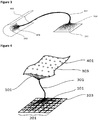
- FIG 3 is a schematic diagram showing the device of the invention used to apply IR radiation to a non-flat target surface.
- IR radiation is emitted from the IR source 201.
- the IR source 201 may be an array of individual IR LEDs 103, although this is not shown in the figure.
- the IR radiation emitted from the IR source 201 is coupled into the inlets of a set of glass fibres 101. This may be via one or more optical elements 102 (not shown), optionally a lens.
- the outlets of the glass fibres 101 are held in place by a support 303, which allows the outlets of the glass fibres 101 to lie in a flexible outlet surface 303.
- the glass fibres are collected into a fibre bundle 301 between the IR source 201 and the outlet surface 303.
- the flexible outlet surface 303 is adapted to and located next to the surface of a target 302. This allows IR radiation from the IR source 201 to be applied to the surface of the target 302 to heat it.
- Figure 4 is a schematic diagram showing the device of the invention having an array 201 of IR LEDs 103 and a flexible outlet surface 303.
- IR radiation is emitted from the IR source 201.
- the IR source 201 is shown in the figure as an array 201 of individual IR LEDs 103.
- the IR radiation emitted from the IR source 201 is coupled into the inlets of a set of glass fibres 101. This may be via one or more optical elements 102 (not shown), optionally a lens.
- the IR LEDs 103 of the array 201 are in one-to-one correspondence with the glass fibres 101.
- the outlets 401 of the glass fibres 101 are held in place by a support 303, which allows the outlets 401 of the glass fibres 101 to lie in a flexible outlet surface 303.
- the glass fibres are collected into a fibre bundle 301 between the IR source 201 and the outlet surface 303.
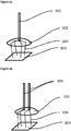
- FIG. 5 is a schematic diagram showing a support element connecting two glass fibres 101.
- the support element comprises arms 502 which are pinioned together at a nexus 503.
- Clamps 501 are pinioned to the ends of the arms 502.
- the claims 501 clamp around the glass fibres 101.
- the support elements hold the glass fibres in a relative spatial configuration, but allow movement to other relative spatial configurations.
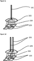
- Figure 6 is a schematic diagram showing a connected network formed by support elements 601. Each support element is attached to two glass fibres 101.
- the glass fibres 101 are arranged in a square matrix with each glass 101 fibre being connected to the 4 adjacent and 4 diagonal neighbouring glass fibres 101 by a support element 601.
- the support elements 601 hold the glass fibres 101 in a relative spatial configuration, but allow movement to other relative spatial configurations.
- the support elements 601 can be according to figure 5 .
- FIG. 7 is a schematic diagram showing glass fibres connected by support elements.
- Each support element makes connections 702 between 4 glass fibres 101 and a nexus 701.
- the glass fibres 101 are arranged in a square matrix with each glass 101 fibre being connected to the 4 diagonal neighbouring glass fibres 101 by support elements.
- the support elements hold the glass fibres 101 in a relative spatial configuration, but allow movement to other relative spatial configurations.
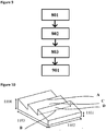
- Figure 8 is a process flow diagram showing the inventive process for heating a target.
- a device according to the invention is provided along with a target surface.
- the outlet surface of the device is adapted to the target surface.
- the adapted outlet surface and the target surface are complementary, thereby allowing the outlet surface to be positioned at a uniform distance from the target surface.
- IR radiation is applied to the target surface from the outlet surface, thereby heating the target surface.
- Figure 9 is a process flow diagram showing the inventive process for making a composite.
- the first 801 second 802 and third 803 steps proceed as in figure 8 .
- the heat treated target surface obtained following step 803 is in a softened or melted state.
- a further part is provided and brought into contact with the heat treated target surface.
- the softened or melted target surface allows a weld joint to be made with the further part.
- the process of the present invention can be used to heat a further target surface on the further part also.
- the weld joint between the target surface and the further part is made by contacting the heat treated target surface with the further heat treated target surface.
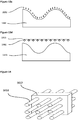
- Figure 10 is a schematic diagram showing a target having a saw tooth target surface.
- the target surface has peaks at a height of 5 cm 1104 from the base and troughs at a height of 1 cm 1101 from the base.
- the base is 25cm 1102 by 30cm 1103. Measuring positions are indicated as follows: A is at the top of a peak, B is at the bottom of a trough, C is half way up a gradient between a peak and a trough and D is half way up a sheer vertical section between a peak and a trough.
- Figure 11 is a schematic diagram showing a target having an undulating target surface.
- the target surface has peaks at a height of 5 cm 1104 from the base and troughs at a height of 1 cm 1101 from the base.
- the base is 25cm 1102 by 30cm 1103. Measuring positions are indicated as follows: A is at the top of a peak, B is at the bottom of a trough and C is half way up a gradient between a peak and a trough.
- Figure 12a shows application of IR radiation to the saw tooth target surface of a target 1001 according to figure 10 using a device having a flexible outlet surface 1003.
- the flexible support 1003 is adapted to the shape of the target surface of the target 1001.
- the outlets of glass fibres which are held by the flexible support 1003 are aligned with the support 1003.
- IR radiation 1002 is therefore emitted perpendicular to the outlet surface and is applied to the target surface in a direction perpendicular to the target surface. This allows a uniform application of IR radiation 1002 to the target surface.
- Figure 12b shows application of IR radiation to the saw tooth target surface of a target 1001 according to figure 10 using a device having a rigid planar outlet surface 1003.
- the planar support 1003 is positioned in a plane parallel to the base of the target 1001.
- the outlets of glass fibres which are held by the planar support 1003 are aligned with the support 1003.
- IR radiation 1002 is therefore emitted perpendicular to the plane of the support and is applied to the target surface in a direction perpendicular to the target basal plane.
- This configuration does not produce a uniform application of IR radiation to the target surface.
- the surface of the peaks receives more radiation than the surface of the troughs and the vertical sections joining adjacent peak and trough receive very little IR radiation because the radiation is emitted in a direction which is oblique to the target surface there.
- Figure 12c shows application of IR radiation to the saw tooth target surface of a target 1001 according to figure 10 using a device having no support.
- Individual glass fibres are adapted to the shape of the target surface and are arranged to have their outlet face perpendicular to the basal plane of the target. IR radiation is thereby applied to the target surface in a direction perpendicular to the basal plane.
- This configuration does not produce a uniform application of IR radiation to the target surface.
- the vertical sections joining adjacent peak and trough receive very little IR radiation because the radiation is emitted in a direction which is oblique to the target surface there.
- Figure 12d shows application of IR radiation to the saw tooth target surface of a target 1001 according to figure 10 using an array of IR LED emitters arranged on a rigid planar support 1003.
- the individual IR LEDs emit radiation 1002 with a higher divergence than IR radiation emitted from a glass fibre.
- This configuration does not produce a uniform application of IR radiation to the target surface.
- the surface of the peaks receives more radiation than the surface of the troughs and the vertical sections joining adjacent peak and trough receive very little IR radiation because the radiation is emitted substantially in a direction which is oblique to the target surface there.
- Figures 13a-13d show application of radiation to the undulating target surface of target of figure 11 . Similar principles are observed as for the saw tooth target of figures 12a-12d .
- Figure 14 shows a set of glass fibres 903 which is held in a square lattice by a layer of rubber 902. The layer of rubber has been formed around the glass fibres 901.
- Optical power flux is measured according to CIE 84-1989.
- Peak emission wavelength and bandwidth are measured according to CIE 63-1984.
- Peak emission wavelength is at a maximum in the spectral emission density.
- Bandwidth is the width of the distribution about the peak emission wavelength for which spectral emission density is greater than or equal to half the peak value.
- Adhesion is measured using the tape test of ASTM D3359-17 using a ranking from 1 to 5, where 1 is the poorest performing and 5 is the best performing.
- a device was provided according to figures 2 and 4 .
- the square array had a spacing between adjacent IR LEDs of 2.5 mm. The array therefore had an overall size of 39.5 mm by 39.5 mm.
- Over each IR LED was positioned a circular collimating lens commercially available from the company Heraeus Noblelight GmbH, Germany having a cross sectional diameter of 1.25 mm. Each lens was at a distance of 1 mm from the corresponding IR LED with the flat side directed towards the IR LED.
- the other end of each glass fibre was incorporated into a flexible support as shown in figure 14 by setting a 5 mm thick layer of UV hardening silicone rubber available from Dowcorning around the fibres to hold their outlet surfaces in a 12 by 12 square array of size 39.5 mm by 39.5 mm.
- the outlet surface was adapted to a non-flat target surface at a distance of 5 mm as shown in figure 10 made of acrylonitrile butadiene styrene such that the outlet surface was at a distance of 5 mm from the target surface.
- IR radiation was applied to the target surface for 5 s by activating the IR LED array.
- Example 1a was repeated but with the IR LED array replaced with an IR VCSEL array.
- the array was a hexagonally packed array of wafer-level integrated VCSEL emitters commercially available from the company Princeton Optronics Inc., USA.
- the emitter surface had a lattice parameter of approximately 0.022 mm and the array had an overall size of 39.5 mm by 39.5 mm.
- Lenses of the same type as in example 1 were positioned over the emitter array with the flat side directed towards the emitter array. The lenses were position in a 12 by 12 square array with lattice parameter 3.5 mm and at a distance of 1 mm from the emitter array.
- the other end of each glass fibre was incorporated into a flexible support as shown in figure 14 by setting a 5 mm thick layer of UV hardening silicone rubber available from Dowcorning around the fibres to hold their outlet surfaces in a 12 by 12 square array of size 39.5 mm by 39.5 mm.
- the outlet surface was adapted to a non-flat target surface as shown in figure 10 made of acrylonitrile butadiene styrene such that the outlet surface was at a distance of 5 mm from the target surface.
- IR radiation was applied to the target surface for 1 s by activating the IR VCSEL array.
- the array of IR LEDs of example 1a was employed without the corresponding lenses, glass fibres or support for the outlet surface. IR radiation was applied to the same surface as in example 1a by positioning the array at a distance of 5 mm from the peaks on the target surface. IR radiation was likewise applied to the target surface for 5 s by activating the IR LED array.
- the array of IR VCSELs of example 1b was employed without the corresponding lenses, glass fibres or support for the outlet surface. IR radiation was applied to the same surface as in example 1b by positioning the array at a distance of 5 mm from the peaks on the target surface. IR radiation was likewise applied to the target surface for 1 s by activating the IR VCSEL array.
- the array of example 1a was employed except that the support was replaced with a rigid planar support.
- the outlet surface had a 12 by 12 square array having lattice parameter 3.5 mm.
- the outlet surface was positioned 5 mm from the peaks on the emitter surface. IR radiation was applied to the target surface for 5 s by activating the IR LED array.
- the array of example 1b was employed except that the support was replaced with a rigid planar support.
- the outlet surface had a 12 by 12 square array having lattice parameter 3.5 mm.
- the outlet surface was positioned 5 mm from the peaks on the emitter surface.
- IR radiation was applied to the target surface for 1 s by activating the IR VCSEL array.
- example 1a The array of example 1a was employed except that the glass fibres were not held by a support.
- the outlet ends of the glass fibres were arranged in a 12 by 12 array over the target surface having a lattice parameter 3.5 mm with their outlet face being parallel to the base of the target and the outlets each lying at a distance of 0 mm from the target surface.
- IR radiation was applied to the target surface for 5 s by activating the IR LED array.
- example 1a The array of example 1a was employed except that the glass fibres were not held by a support.
- the outlet ends of the glass fibres were arranged in a 12 by 12 array over the target surface having a lattice parameter 3.5mm with their outlet face being parallel to the base of the target and the outlets each lying at a distance of 0 mm from the target surface.
- IR radiation was applied to the target surface for 1 s by activating the IR VCSEL array.
- inventive examples 1a and 1b provided a higher uniformity of heating to the target surface than the corresponding comparative examples 2a and 2b respectively.
- Examples 1a, 1b, 2a, 2b, 3a, 3b, 4a and 4b were repeated, but with a target having the shape shown in figure 11 rather than the shape shown in figure 10 .
- the results of the softness testing are presented in table 2.
- Table 2 Example Temperature at A [°C] Temperature at B [°C] Temperature at C [°C] 5a 150 150 150 5b 150 150 150 6a 150 75 100 6b 150 75 100 7a 150 75 100 7b 150 75 100 8a 150 150 150 8b 150 150 150 150
- Examples 1a-8b were repeated except that the target was made of silicon (wafer) and was provided with a coating of polyimide resist precursor. Following irradiation for 5 s, the coating was tested for adhesion onto the silicon wafer surface by a tape test. The results are shown in tables 3 and 4.
Landscapes
- Radiation-Therapy Devices (AREA)
- Physical Or Chemical Processes And Apparatus (AREA)
Priority Applications (2)
| Application Number | Priority Date | Filing Date | Title |
|---|---|---|---|
| EP17194235.2A EP3462810A1 (fr) | 2017-09-29 | 2017-09-29 | Dispositif de chauffage d'une cible ayant un rayonnement ir |
| PCT/EP2018/076311 WO2019063712A1 (fr) | 2017-09-29 | 2018-09-27 | Dispositif de chauffe d'une cible au moyen d'un rayonnement ir |
Applications Claiming Priority (1)
| Application Number | Priority Date | Filing Date | Title |
|---|---|---|---|
| EP17194235.2A EP3462810A1 (fr) | 2017-09-29 | 2017-09-29 | Dispositif de chauffage d'une cible ayant un rayonnement ir |
Publications (1)
| Publication Number | Publication Date |
|---|---|
| EP3462810A1 true EP3462810A1 (fr) | 2019-04-03 |
Family
ID=60043000
Family Applications (1)
| Application Number | Title | Priority Date | Filing Date |
|---|---|---|---|
| EP17194235.2A Withdrawn EP3462810A1 (fr) | 2017-09-29 | 2017-09-29 | Dispositif de chauffage d'une cible ayant un rayonnement ir |
Country Status (2)
| Country | Link |
|---|---|
| EP (1) | EP3462810A1 (fr) |
| WO (1) | WO2019063712A1 (fr) |
Citations (4)
| Publication number | Priority date | Publication date | Assignee | Title |
|---|---|---|---|---|
| JP2002147762A (ja) * | 2000-11-14 | 2002-05-22 | Fuji Photo Film Co Ltd | 食品調理器 |
| US6713713B1 (en) * | 2002-12-18 | 2004-03-30 | Branson Ultrasonics Corporation | Lens to adapt laser intensity for uniform welding |
| EP2543472A1 (fr) * | 2011-07-04 | 2013-01-09 | Rolls-Royce plc | Élément de fixation d'un adhésif pour tenir une pièce de travail |
| US20160007412A1 (en) * | 2014-07-02 | 2016-01-07 | Applied Materials, Inc. | Apparatus, systems, and methods for temperature control of substrates using embedded fiber optics and epoxy optical diffusers |
-
2017
- 2017-09-29 EP EP17194235.2A patent/EP3462810A1/fr not_active Withdrawn
-
2018
- 2018-09-27 WO PCT/EP2018/076311 patent/WO2019063712A1/fr not_active Ceased
Patent Citations (4)
| Publication number | Priority date | Publication date | Assignee | Title |
|---|---|---|---|---|
| JP2002147762A (ja) * | 2000-11-14 | 2002-05-22 | Fuji Photo Film Co Ltd | 食品調理器 |
| US6713713B1 (en) * | 2002-12-18 | 2004-03-30 | Branson Ultrasonics Corporation | Lens to adapt laser intensity for uniform welding |
| EP2543472A1 (fr) * | 2011-07-04 | 2013-01-09 | Rolls-Royce plc | Élément de fixation d'un adhésif pour tenir une pièce de travail |
| US20160007412A1 (en) * | 2014-07-02 | 2016-01-07 | Applied Materials, Inc. | Apparatus, systems, and methods for temperature control of substrates using embedded fiber optics and epoxy optical diffusers |
Also Published As
| Publication number | Publication date |
|---|---|
| WO2019063712A1 (fr) | 2019-04-04 |
Similar Documents
| Publication | Publication Date | Title |
|---|---|---|
| CN103827718B (zh) | 用于固化光纤的具有共定位焦点的双椭圆反射器 | |
| CN106463404B (zh) | 有沟槽引导式光纤加热的温度控制设备、基板温度控制系统、电子器件处理系统及处理方法 | |
| US7202489B2 (en) | LED modifying apparatus and method | |
| KR102164611B1 (ko) | 매립형 광섬유들 및 에폭시 광학 확산기들을 사용하는 기판들의 온도 제어를 위한 장치, 시스템들, 및 방법들 | |
| CN105377784B (zh) | 固化装置、用于紫外固化的光化系统和光化方法 | |
| US8655128B2 (en) | Optical fiber bundle and optical irradiator | |
| EP1697681A2 (fr) | Appareil et procede de modification de diodes electroluminescentes | |
| US9388967B2 (en) | Edge weighted spacing of LEDs for improved uniformity range | |
| EP3462810A1 (fr) | Dispositif de chauffage d'une cible ayant un rayonnement ir | |
| EP3689103B1 (fr) | Dispositif de chauffage sélectif d'une cible avec un rayonnement ir | |
| US12397476B2 (en) | Nested elliptic reflector for curing optical fibers | |
| CN212182757U (zh) | 一种阵列微透镜固化加热头及具有其的激光设备 | |
| CN212182758U (zh) | 一种用于激光固化加热的多头激光设备 | |
| JPS61259202A (ja) | エラストマ−製光フアイバ−の製造方法 |
Legal Events
| Date | Code | Title | Description |
|---|---|---|---|
| PUAI | Public reference made under article 153(3) epc to a published international application that has entered the european phase |
Free format text: ORIGINAL CODE: 0009012 |
|
| AK | Designated contracting states |
Kind code of ref document: A1 Designated state(s): AL AT BE BG CH CY CZ DE DK EE ES FI FR GB GR HR HU IE IS IT LI LT LU LV MC MK MT NL NO PL PT RO RS SE SI SK SM TR |
|
| AX | Request for extension of the european patent |
Extension state: BA ME |
|
| STAA | Information on the status of an ep patent application or granted ep patent |
Free format text: STATUS: THE APPLICATION IS DEEMED TO BE WITHDRAWN |
|
| 18D | Application deemed to be withdrawn |
Effective date: 20191005 |