EP3464764B1 - Serrure de véhicule automobile - Google Patents
Serrure de véhicule automobile Download PDFInfo
- Publication number
- EP3464764B1 EP3464764B1 EP17727553.4A EP17727553A EP3464764B1 EP 3464764 B1 EP3464764 B1 EP 3464764B1 EP 17727553 A EP17727553 A EP 17727553A EP 3464764 B1 EP3464764 B1 EP 3464764B1
- Authority
- EP
- European Patent Office
- Prior art keywords
- sleeve element
- bearing sleeve
- motor vehicle
- bearing
- lever
- Prior art date
- Legal status (The legal status is an assumption and is not a legal conclusion. Google has not performed a legal analysis and makes no representation as to the accuracy of the status listed.)
- Active
Links
Images

Classifications
-
- E—FIXED CONSTRUCTIONS
- E05—LOCKS; KEYS; WINDOW OR DOOR FITTINGS; SAFES
- E05B—LOCKS; ACCESSORIES THEREFOR; HANDCUFFS
- E05B79/00—Mounting or connecting vehicle locks or parts thereof
- E05B79/02—Mounting of vehicle locks or parts thereof
- E05B79/08—Mounting of individual lock elements in the lock, e.g. levers
-
- E—FIXED CONSTRUCTIONS
- E05—LOCKS; KEYS; WINDOW OR DOOR FITTINGS; SAFES
- E05B—LOCKS; ACCESSORIES THEREFOR; HANDCUFFS
- E05B79/00—Mounting or connecting vehicle locks or parts thereof
- E05B79/10—Connections between movable lock parts
- E05B79/20—Connections between movable lock parts using flexible connections, e.g. Bowden cables
-
- E—FIXED CONSTRUCTIONS
- E05—LOCKS; KEYS; WINDOW OR DOOR FITTINGS; SAFES
- E05B—LOCKS; ACCESSORIES THEREFOR; HANDCUFFS
- E05B15/00—Other details of locks; Parts for engagement by bolts of fastening devices
- E05B15/04—Spring arrangements in locks
- E05B2015/0403—Wound springs
- E05B2015/0406—Wound springs wound in a cylindrical shape
- E05B2015/041—Wound springs wound in a cylindrical shape loaded perpendicular to cylinder axis
Definitions
- the invention relates to a motor vehicle lock according to claim 1 and a method for assembling such a motor vehicle lock according to claim 13.
- the motor vehicle lock in question can be assigned to all types of locking elements of a motor vehicle. These include doors, in particular side or rear doors, trunk lids, tailgates, bonnets, load compartment floors or the like.
- the motor vehicle lock is equipped with bearing domes on each of which a plurality of axially spaced levers are mounted.
- the resulting set of levers is often supported on housing components via spacer sleeves.
- the invention is based on the problem of specifying a motor vehicle lock which allows a tolerance-insensitive mounting of, in particular, a plurality of levers on a geometrical lever axis with little manufacturing effort.
- the proposed motor vehicle lock is equipped with a lock mechanism and with a lock housing to accommodate the lock mechanism.
- the lock mechanism has at least one actuating lever pivotable about a geometric lever axis, a bearing sleeve element being provided on which the actuating lever is radially supported.
- the actuating lever is not only mounted radially on the bearing sleeve element, but also mounted axially. It is essential that the actuating lever is coupled to the bearing sleeve element via a bayonet lock for axially bilateral mounting. It is also essential that, within the framework of the assembly of the motor vehicle lock, the actuating lever can be preassembled together with the bearing sleeve element to form a separate unit by producing the bayonet lock.
- the design of the axial lock between the actuating lever and the bearing sleeve element as a bayonet lock is advantageous in that the bayonet lock can be generated with simple assembly movements, in particular in an automated manner, and that the bayonet lock ensures a secure, axially two-sided mounting of the actuating lever without great mechanical effort can be implemented.
- the preferred configurations according to claims 2 to 5 relate to preferred variants for producing the bayonet lock.
- the particularly preferred embodiment according to claim 5 offers the possibility of a simple pre-assembly of the actuating lever and bearing sleeve element in that no precise and therefore complex assembly movements are required during pre-assembly and with a suitable design.
- in the installed state of the motor vehicle lock it is ensured solely by restricting the movement of the actuating lever and the bearing sleeve element that unlocking of the bayonet lock is blocked. A separate locking element for locking the bayonet lock is accordingly not required.
- the bearing sleeve element is axially supported on two sides and can in this respect serve as a spacer.
- the bearing sleeve element provides an axial support, that is, an axial bearing, for at least one additional lever. Because the bearing sleeve element, which is preferably mounted on the bearing dome, simultaneously provides an axial bearing for at least one additional lever, the build-up of undesired tolerance chains from one lever to the other lever can be reliably avoided.
- the actuating lever and the bearing sleeve element form a pre-assembled unit with the formation of the bayonet lock, the pre-assembled unit then being otherwise mounted on the motor vehicle lock.
- the pre-assembly of the actuating lever and the bearing sleeve element allow the parallelization of process steps, the proposed construction of the bearing sleeve element ensuring compliance with predetermined tolerances.
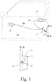
- the motor vehicle lock 1 shown in the drawing is assigned to a side door 1a of a motor vehicle.
- the motor vehicle lock 1 can in principle be used on all types of locking elements of a motor vehicle. In this respect, reference may be made to the introductory part of the description.
- the basic structure of the motor vehicle lock 1 comprises the locking elements lock latch 2 and pawl 3, which interact in a conventional manner.
- the latch 2 can be brought into at least one closed position in which it is in holding engagement with a closing element 4, in particular a striker or a striker.
- the latch 2 is held in its closed position by the pawl 3.
- the excavation of the The pawl 3 is connected to the release of the latch 2 into its open position, which is associated with the release of the locking element 4.
- the side door 1a receives the motor vehicle lock 1, while the locking element 4 is arranged on the motor vehicle body.
- the reverse can also be provided.
- Fig. 1 further shows that an outside door handle 5 and an inside door handle 6 are provided which are each coupled to the motor vehicle lock 1 via Bowden cables 5a, 6a. Depending on the closed state of the motor vehicle lock 1, the pawl 3 can be lifted out by actuating the outside door handle 5 or the inside door handle 6.
- the illustrated motor vehicle lock 1 is equipped with a lock mechanism 7, which here includes all the mechanical components required to implement the lock functions.
- the lock mechanism 7 is accommodated in a lock housing 8, which does not necessarily have to be designed to be closed.
- the term "lock housing” is to be understood broadly. In principle, it can also be that a rear panel or a locking plate is part of the lock housing 8a in this sense.
- the lock mechanism 7 has at least one actuating lever 11 that can be pivoted about a geometric lever axis 10.
- the operating lever 11 is an external operating lever which is coupled to the outside door handle 5 via the Bowden cable 11a.
- Fig. 2 shows that a bearing sleeve element 12 is provided on which the actuating lever 11 is mounted radially. This is best seen by looking at the Fig. 2 , 3 and 4th .
- the actuating lever 11 is axially supported on two sides on the bearing sleeve element 12. This means that the axial adjustability of the actuating lever 11 in both axial directions is defined by the axially bilateral bearing.
- the actuating lever 11 is coupled to the bearing sleeve element 12 via a bayonet catch 13. This in turn results from a synopsis of the Fig. 2 , 3 and 4th .
- At least two actuation levers 11, preferably more than two actuation levers 11, can also be mounted on the bearing sleeve element 12.
- bearing sleeve element 12 preferably more than two bearing sleeve elements 12, are provided, each of which supports at least one actuating lever 11.
- a fixing arrangement (not shown) is preferably provided between the actuating lever 11 and the bearing sleeve element 12.
- the fixing arrangement can be a latching arrangement which has to be locked in place when the bayonet catch 13 is produced. It is also conceivable that during the manufacture of the bayonet lock 13 crushing ribs have to be traversed, which ensure that the bayonet lock cannot be released without an increased expenditure of force.
- a synopsis of the Fig. 3 and 4th shows that the bearing sleeve element 12 is designed to be non-rotatable with the lock housing 8 in relation to the lever axis 10.
- the bearing sleeve element 12 has a support arm 15 which is supported against the lock housing 8 in a rotationally fixed manner with respect to the lever axis 10.
- the support arm 15 has an opening 15a which is pushed onto a bearing dome 16 when the unit 14 is assembled. The fact that the bearing dome 16 is spaced from the lever axis 10 results in the desired support effect.
- the bayonet lock 13 is formed by a bayonet recess 17 on the bearing sleeve element 12 on the one hand and by a bayonet counter-recess 18 on the actuating lever 11 on the other hand.
- the components operating lever 11 and bearing sleeve element 12 can be derived from the in Fig. 2 Slide out the position shown axially into one another.
- the bayonet lock 13 can be moved into the positions shown in FIG Fig. 3 Bring shown, locked state in which the bayonet recess 17 and the bayonet counter-recess 18 form an undercut.
- Pivoting back leads to the bayonet catch 13 assuming its unlocked state. It is essential that only in the locked state ( Fig. 3 ) the axially bilateral bearing between the actuating lever and the bearing sleeve element 12 is provided. In the unlocked state ( Fig. 2 ) on the other hand, an axial adjustment of the actuating lever 11 and the bearing sleeve element 12 is possible.
- the proposed solution enables a particularly secure axially two-sided mounting of the actuating lever 11 on the bearing sleeve element 12.
- the actuating lever 11 and the bearing sleeve element 12 in the installed state of the motor vehicle lock 1 assume a locking pivot position with respect to one another with respect to the bayonet catch 13, so that the bayonet catch 13 is in its locked state as discussed above.
- the arrangement is furthermore preferably such that the actuating lever 11 and the bearing sleeve element 12 in the installed state of the motor vehicle lock 1 are restricted in movement in such a way that unlocking of the bayonet catch 13 is blocked.
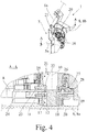
- FIG. 4 The sectional view according to Fig. 4 shows that the bearing sleeve element 12 is axially supported on two sides. There is a support point on part of the lock housing 8, here on an in Fig. 4 only indicated housing cover 8a.
- the bearing sleeve element 12 has an axial extension 19, on which the bayonet recess 17 is arranged here and preferably.
- the axial extension 19 has a further function, namely the function of the axial support of the bearing sleeve element 12 on the lock housing 8, here on the housing cover 8a.
- the axial extension 19 takes on a further function, namely the function of receiving a spring element 20, which in a particularly preferred embodiment is a helical spring element, in particular a leg spring element, for the actuating lever 11.
- the spring element 20 is assigned to another component of the lock mechanism 7.
- Fig. 4 shows that the bearing sleeve element 12 has the function of a spacer, by means of which the actuating lever 11 is held at a predetermined distance from the housing cover 8a.
- the motor vehicle lock 1 has a further bearing dome 21, the bearing sleeve element 12, as in FIG Fig. 4 is arranged coaxially to the bearing dome 21.
- the bearing sleeve element 12 is pushed onto the bearing dome 21.
- the bearing sleeve element 12 can be inserted into the bearing dome 21 or attached to the bearing dome 21.
- the bearing dome 21 is connected to a part of the lock housing 8, preferably with a housing trough 8b, here and preferably in one piece.
- the bearing sleeve element 12 is supported on the housing cover 8a via its axial extension 19.
- the bearing sleeve element 12 is supported axially at its end facing away from the housing cover 8a on the bearing dome 21, here and preferably on a radial shoulder 22 of the bearing dome 21.
- This preferably results in the bearing sleeve element 12 being fixed, in particular clamped, between the housing cover 8a of the lock housing 8 and the bearing dome 21. Additional measures for fastening the bearing sleeve element 12, which can be, for example, an additional riveted connection or the like, are thus omitted.
- the lock mechanism 7 preferably has at least one additional lever 23, 24, here and preferably two additional levers 23, 24, which can be pivoted about the geometric lever axis 10 and which is or are pivotable about the geometric lever axis 10.
- the additional levers 23, 24 are supported here and preferably on the bearing dome 21.
- the bearing points of the additional levers 23, 24 are axially spaced from the bearing point of the actuating lever 11.
- the additional levers 23, 24, like the bearing sleeve element 12, are pushed onto the bearing dome 21.
- the additional lever 23 is the internal operating lever which, when the motor vehicle lock 1 is installed, is coupled to the inside door handle 6 via the Bowden cable 6a.
- the additional lever 24 is a so-called release lever which, depending on the state of the lock, can be actuated by the external actuating lever 11 and / or the internal actuating lever 23 and acts on the pawl 3.
- the two additional levers 23, 24 are arranged between a further radial shoulder 25 of the bearing dome 21 and a circumferential collar 26 of the bearing sleeve element 12 and are thereby axially supported on two sides.
- the axial mounting of the actuating lever 11 on the one hand and the additional levers 23, 24 on the other hand have no alternating, tolerance-related influence on one another.
- the bearing sleeve element 12 has a further axial extension 27, which is designed as an internal operating lever with the Additional lever 23 is in engagement or can be brought, and which supports this additional lever 23 axially on one side.
- the levers 11, 23, 24 of the lever assembly 9 can be kept in an axially defined position with the solution according to the proposal, without this leading to a high level of manufacturing complexity.
- the axial extension 27 protrudes through openings 28 in the release lever 24, which further increases the compactness of the structure overall.
- the actuating lever 11 and the bearing sleeve element 12 form the above-mentioned pre-assembled unit 14 while forming the bayonet lock 13, the pre-assembled unit 14 then subsequently being mounted on the motor vehicle lock 1.
- the pre-assembly results from the transition from Fig. 2 on Fig. 3 .
- the assembly of the preassembled unit 14 on the motor vehicle lock 1 also results from the transition from Fig. 3 on Fig. 4 .
- the motor vehicle lock 1 has a bearing dome 21 mentioned above, the at least one additional lever 23 being attached to the bearing dome 21 in a first step, the preassembled unit being attached to the bearing dome 21 in a second step. Subsequently, it is preferably provided that in a third step the housing cover 8a is otherwise placed on the lock housing 8, whereby the bearing sleeve element 12 is axially supported.
- the bearing sleeve element 12 is made from a plastic material.
- the bearing dome 21 is preferably also made from a plastic material.
- the bearing sleeve element 12 and / or the bearing dome 21 can, however, also be reinforced by other materials, in particular by steel materials. In particular it can be provided that the bearing dome 21 has a steel mandrel for mechanical reinforcement.
Landscapes
- Lock And Its Accessories (AREA)
- Automobile Manufacture Line, Endless Track Vehicle, Trailer (AREA)
- Snaps, Bayonet Connections, Set Pins, And Snap Rings (AREA)
Claims (15)
- Serrure de véhicule automobile comprenant un mécanisme de serrure (7) et un boîtier de serrure (8) pour recevoir le mécanisme de serrure (7), le mécanisme de serrure (7) présentant au moins un levier d'actionnement (11) pouvant pivoter autour d'un axe géométrique de levier (10), un élément de douille palier (12) étant prévu, sur lequel le levier d'actionnement (11) est supporté radialement, le levier d'actionnement (11) étant supporté axialement des deux côtés sur l'élément de douille palier (12) et étant pour cela accouplé à l'élément de palier (12) par le biais d'une fermeture à baïonnette (13), le levier d'actionnement (11) et l'élément de douille palier (12), dans le cadre de la fabrication de la serrure de véhicule automobile (1), pouvant être prémontés en réalisant la fermeture à baïonnette (13) de manière à obtenir une unité séparée (14).
- Serrure de véhicule automobile selon la revendication 1, caractérisée en ce que l'élément de douille palier (12), par rapport à l'axe de levier (10), est réalisé de manière solidaire en rotation du boîtier de serrure (8), de préférence en ce que l'élément de douille palier (12) présente un bras de support (15) qui, par rapport à l'axe de levier (10), s'appuie de manière solidaire en rotation par rapport au boîtier de serrure (8).
- Serrure de véhicule automobile selon la revendication 1 ou 2, caractérisée en ce que la fermeture à baïonnette (13) est formée d'une part par une formation de baïonnette (17) au niveau de l'élément de douille palier (12) et d'autre part par une formation conjuguée de baïonnette (18) au niveau du levier d'actionnement (11).
- Serrure de véhicule automobile selon l'une quelconque des revendications précédentes, caractérisée en ce que la fermeture à baïonnette (13) peut être amenée dans un état verrouillé et dans un état déverrouillé par pivotement du levier d'actionnement (11) par rapport à l'élément de douille palier (12) autour de l'axe de levier (10) et en ce que la fermeture à baïonnette (13) fournit seulement dans l'état verrouillé le support sur palier axial des deux côtés entre le levier d'actionnement (11) et l'élément de palier (12) et permet, dans l'état déverrouillé, un déplacement axial du levier d'actionnement (11) et de l'élément de douille palier (12) l'un par rapport à l'autre.
- Serrure de véhicule automobile selon l'une quelconque des revendications précédentes, caractérisée en ce que le levier d'actionnement (11) et l'élément de douille palier (12) adoptent, dans l'état installé de la serrure de véhicule automobile (1) par rapport à la fermeture à baïonnette (13), une position de pivotement de verrouillage l'un par rapport à l'autre, de préférence en ce que le levier d'actionnement (11) et l'élément de douille palier (12), dans l'état installé de la serrure de véhicule automobile (1), ont un mouvement limité de telle sorte qu'un déverrouillage de la fermeture à baïonnette (13) soit empêché.
- Serrure de véhicule automobile selon l'une quelconque des revendications précédentes, caractérisée en ce que l'élément de douille palier (12) est supporté axialement des deux côtés, de préférence en ce que l'élément de douille palier (12) s'appuie axialement au niveau d'une partie du boîtier de serrure (8), en particulier au niveau d'un couvercle de boîtier (8a).
- Serrure de véhicule automobile selon l'une quelconque des revendications précédentes, caractérisée en ce que l'élément de douille palier (12) présente une saillie axiale (19), de préférence en ce que la formation de baïonnette (17) est disposée au niveau de la saillie axiale (19), et/ou en ce que la saillie axiale (19) sert au support axial de l'élément de douille palier (12) au niveau du boîtier de serrure (8), en particulier au niveau du couvercle de boîtier (8a), et/ou en ce que la saillie axiale (19) sert à recevoir un élément de ressort (20), en particulier un élément de ressort hélicoïdal, pour le levier d'actionnement (11) ou pour un autre composant du mécanisme de serrure (7).
- Serrure de véhicule automobile selon l'une quelconque des revendications précédentes, caractérisée en ce qu'un dôme de palier (21) est prévu, et en ce que l'élément de douille palier (12) est disposé coaxialement par rapport au dôme de palier (21), de préférence en ce que l'élément de douille palier (12) est enfiché sur le dôme de palier (21) ou est enfiché dans le dôme de palier (21) ou est appliqué sur le dôme de palier (21), de préférence en ce que le dôme de palier (21) est connecté à une partie du boîtier de serrure (8), en particulier d'une seule pièce.
- Serrure de véhicule automobile selon la revendication 8, caractérisée en ce que l'élément de douille palier (12) s'appuie axialement sur le dôme de palier (21), en particulier au niveau d'un épaulement radial (22) du dôme de palier (21), de préférence en ce que l'élément de douille palier (12) est fixé, en particulier serré, entre le couvercle de boîtier (8a) du boîtier de serrure (8) et le dôme de palier (21).
- Serrure de véhicule automobile selon la revendication 8 ou 9, caractérisée en ce que le mécanisme de serrure (7) présente au moins un levier supplémentaire (23, 24) pouvant pivoter autour de l'axe géométrique de levier (10), de préférence deux leviers supplémentaires (23, 24) additionnels pouvant pivoter autour de l'axe de levier (10), et en ce que l'au moins un levier supplémentaire (23, 24) est supporté sur le dôme de palier (21).
- Serrure de véhicule automobile selon la revendication 10, caractérisée en ce qu'au moins un levier supplémentaire (21) est supporté axialement des deux côtés d'une part par l'élément de douille palier (12), en particulier un épaulement radial (26) sur l'élément de douille palier (12), et d'autre part par le dôme de palier (21), en particulier un épaulement radial sur le dôme de palier (21).
- Serrure de véhicule automobile selon la revendication 10 ou 11, caractérisée en ce que l'élément de douille palier (12) présente une saillie axiale (27) qui peut être amenée en prise avec un levier supplémentaire (23, 24) supporté sur le dôme de palier (21), et qui supporte axialement d'un côté ce levier supplémentaire (23, 24) .
- Procédé de montage d'une serrure de véhicule automobile (1) selon l'une quelconque des revendications précédentes, dans lequel, dans une étape de prémontage, le levier d'actionnement (11) et l'élément de douille palier (12) constituent une unité prémontée (14) en réalisant la fermeture à baïonnette (13), et l'unité prémontée (14) étant par ailleurs ensuite montée sur la serrure de véhicule automobile (1).
- Procédé selon la revendication 13, caractérisé en ce que la serrure de véhicule automobile (1) présente un dôme de palier (21) et en ce que dans une première étape, l'au moins un levier supplémentaire (23, 24) est enfiché sur le dôme de palier (21) et en ce que dans une deuxième étape, l'unité prémontée (14) est enfichée sur le dôme de palier (21).
- Procédé selon la revendication 13 ou 14, caractérisé en ce que dans une troisième étape, un couvercle de boîtier (8a) est par ailleurs posé sur le boîtier de serrure (8) et de ce fait, l'élément de douille palier (12) est supporté axialement.
Applications Claiming Priority (2)
| Application Number | Priority Date | Filing Date | Title |
|---|---|---|---|
| DE102016110201.6A DE102016110201A1 (de) | 2016-06-02 | 2016-06-02 | Kraftfahrzeugschloss |
| PCT/EP2017/062730 WO2017207422A1 (fr) | 2016-06-02 | 2017-05-26 | Serrure de véhicule automobile |
Publications (2)
| Publication Number | Publication Date |
|---|---|
| EP3464764A1 EP3464764A1 (fr) | 2019-04-10 |
| EP3464764B1 true EP3464764B1 (fr) | 2020-10-14 |
Family
ID=58994916
Family Applications (1)
| Application Number | Title | Priority Date | Filing Date |
|---|---|---|---|
| EP17727553.4A Active EP3464764B1 (fr) | 2016-06-02 | 2017-05-26 | Serrure de véhicule automobile |
Country Status (7)
| Country | Link |
|---|---|
| US (1) | US11371268B2 (fr) |
| EP (1) | EP3464764B1 (fr) |
| JP (1) | JP6824294B2 (fr) |
| KR (1) | KR102178772B1 (fr) |
| CN (1) | CN109328254B (fr) |
| DE (1) | DE102016110201A1 (fr) |
| WO (1) | WO2017207422A1 (fr) |
Families Citing this family (8)
| Publication number | Priority date | Publication date | Assignee | Title |
|---|---|---|---|---|
| DE102015002451A1 (de) * | 2015-02-25 | 2016-08-25 | Kiekert Aktiengesellschaft | Kraftfahrzeugtürverschluss |
| DE102016110201A1 (de) | 2016-06-02 | 2017-12-07 | BROSE SCHLIEßSYSTEME GMBH & CO. KG | Kraftfahrzeugschloss |
| DE102018116313A1 (de) | 2018-04-20 | 2019-10-24 | Kiekert Ag | Schloss für ein kraftfahrzeug |
| DE102018116325A1 (de) * | 2018-07-05 | 2020-01-09 | Kiekert Ag | Schloss für ein Kraftfahrzeug |
| CN110872919B (zh) * | 2018-09-03 | 2023-03-10 | 开开特股份公司 | 汽车锁 |
| DE102019107229A1 (de) * | 2019-03-21 | 2020-09-24 | Kiekert Aktiengesellschaft | Türschloss insbesondere Kraftfahrzeugtürschloss |
| DE102019131179A1 (de) * | 2019-11-19 | 2021-05-20 | Kiekert Aktiengesellschaft | Kraftfahrzeug-Schloss |
| DE102022107657A1 (de) * | 2022-03-31 | 2023-10-05 | Kiekert Aktiengesellschaft | Kraftfahrzeug-Schloss-Betätigungseinheit |
Family Cites Families (23)
| Publication number | Priority date | Publication date | Assignee | Title |
|---|---|---|---|---|
| US2723872A (en) * | 1950-03-29 | 1955-11-15 | Schonitzer | Remote control apparatus |
| DE2101694A1 (de) * | 1971-01-15 | 1972-07-20 | Ymos-Metallwerke Wolf & Becker Gmbh & Co, 6055 Hausen | Türgriff für Kraftfahrzeuge mit flachbauender Hebelübersetzung |
| US5067758A (en) * | 1990-12-21 | 1991-11-26 | Tong-Lung Metal Industry Co., Ltd. | Lock handle assembly with limited angular movement |
| JP3309267B2 (ja) | 1995-06-09 | 2002-07-29 | 株式会社大井製作所 | 複数の回動レバーの支持構造 |
| JP3609217B2 (ja) * | 1996-09-30 | 2005-01-12 | 株式会社大井製作所 | ロック装置 |
| DE10232184A1 (de) | 2002-07-16 | 2004-02-05 | Siemens Ag | Übertragungseinheit für Türschlösser von Kraftfahrzeugen |
| TW590137U (en) * | 2003-04-09 | 2004-06-01 | Tong Lung Metal Ind Co Ltd | Intensifying structure used in horizontal handle |
| AU2006200582B2 (en) * | 2005-02-23 | 2008-09-25 | Aisin Seiki Kabushiki Kaisha | Door lock apparatus for a vehicle |
| JP4618493B2 (ja) | 2005-02-23 | 2011-01-26 | アイシン精機株式会社 | 車両用ドアロック装置 |
| JP4928791B2 (ja) | 2006-01-25 | 2012-05-09 | 三井金属アクト株式会社 | ドアロック装置 |
| DE202007007077U1 (de) * | 2007-05-16 | 2007-08-09 | Kiekert Ag | Befestigungsmittel für Drehteile einer Schließvorrichtung |
| JP2011132771A (ja) * | 2009-12-25 | 2011-07-07 | Aisin Seiki Co Ltd | 車両用ドア開閉装置 |
| IN2015DN00545A (fr) * | 2012-07-31 | 2015-06-26 | Aisin Seiki | |
| DE102013208652A1 (de) * | 2013-05-10 | 2014-11-13 | Kiekert Ag | Befestigungselement zur Anbindung von Übertragungsmitteln an ein Hebelelement |
| JP6331479B2 (ja) * | 2014-02-28 | 2018-05-30 | アイシン精機株式会社 | ロッキングレバー及び車両用ドア開閉装置 |
| DE102014114580A1 (de) * | 2014-10-08 | 2016-04-14 | Kiekert Ag | Kraftfahrzeugtürverschluss |
| DE202014105005U1 (de) * | 2014-10-20 | 2016-01-22 | BROSE SCHLIEßSYSTEME GMBH & CO. KG | Sperrwerk für eine Kraftfahrzeugkomponente |
| EP3192953B1 (fr) * | 2016-01-13 | 2019-10-30 | Huf Hülsbeck & Fürst GmbH & Co. KG | Dispositif de support de poignée de porte de véhicule automobile |
| DE102016110201A1 (de) | 2016-06-02 | 2017-12-07 | BROSE SCHLIEßSYSTEME GMBH & CO. KG | Kraftfahrzeugschloss |
| FR3079258B1 (fr) * | 2018-03-21 | 2022-06-17 | Mgi Coutier Espana Sl | Commande d'ouverture a deverrouillage mecanique de secours |
| DE102018116313A1 (de) * | 2018-04-20 | 2019-10-24 | Kiekert Ag | Schloss für ein kraftfahrzeug |
| US11173968B2 (en) * | 2018-05-17 | 2021-11-16 | Kiekert Ag | Motor vehicle door latch |
| US11761248B2 (en) * | 2018-12-13 | 2023-09-19 | Kiekert Ag | Latch for a motor vehicle |
-
2016
- 2016-06-02 DE DE102016110201.6A patent/DE102016110201A1/de not_active Withdrawn
-
2017
- 2017-05-26 KR KR1020187038003A patent/KR102178772B1/ko active Active
- 2017-05-26 EP EP17727553.4A patent/EP3464764B1/fr active Active
- 2017-05-26 WO PCT/EP2017/062730 patent/WO2017207422A1/fr not_active Ceased
- 2017-05-26 US US16/306,237 patent/US11371268B2/en active Active
- 2017-05-26 JP JP2018563030A patent/JP6824294B2/ja active Active
- 2017-05-26 CN CN201780034435.XA patent/CN109328254B/zh active Active
Non-Patent Citations (1)
| Title |
|---|
| None * |
Also Published As
| Publication number | Publication date |
|---|---|
| CN109328254B (zh) | 2021-07-13 |
| KR20190008963A (ko) | 2019-01-25 |
| WO2017207422A1 (fr) | 2017-12-07 |
| JP6824294B2 (ja) | 2021-02-03 |
| EP3464764A1 (fr) | 2019-04-10 |
| CN109328254A (zh) | 2019-02-12 |
| KR102178772B1 (ko) | 2020-11-13 |
| JP2019525031A (ja) | 2019-09-05 |
| US11371268B2 (en) | 2022-06-28 |
| US20190211588A1 (en) | 2019-07-11 |
| DE102016110201A1 (de) | 2017-12-07 |
Similar Documents
| Publication | Publication Date | Title |
|---|---|---|
| EP3464764B1 (fr) | Serrure de véhicule automobile | |
| EP3612697B1 (fr) | Serrure pour véhicule à moteur | |
| DE102008048773A1 (de) | Kraftfahrzeugtürverschluss | |
| DE102018204199A1 (de) | Fahrzeug-verschluss-verriegelungsanordnung mit anti-verspannungs-verriegelungsmechanismus | |
| EP3994324B1 (fr) | Serrure de porte de véhicule à moteur | |
| EP3059362A1 (fr) | Serrure de véhicule automobile | |
| EP1088142B1 (fr) | Dispositif pour relier une poignee exterieure a un systeme de fermeture | |
| EP3262258B1 (fr) | Fermeture de porte de véhicule automobile | |
| DE19924028A1 (de) | Kraftfahrzeugtür | |
| WO2002022996A1 (fr) | Systeme d'ouverture de porte destine notamment a des vehicules | |
| EP4112851B1 (fr) | Serrure de véhicule automobile, en particulier serrure de portière de véhicule automobile | |
| DE102009051432A1 (de) | Kraftfahrzeugtürverschluss | |
| DE102018113820A1 (de) | Kraftfahrzeugschloss | |
| DE102017122803A1 (de) | Kraftfahrzeugschloss | |
| EP2247810B1 (fr) | Système de verrouillage de porte de véhicule automobile | |
| EP3870785B1 (fr) | Serrure de véhicule automobile, en particulier serrure de porte de véhicule automobile | |
| WO2020048563A1 (fr) | Unité d'entraînement pour des applications en automobile | |
| EP4136300B1 (fr) | Verrou de véhicule automobile, en particulier verrou de portière de véhicule automobile | |
| DE102018121509A1 (de) | Kraftfahrzeugschloss | |
| EP3617432B1 (fr) | Dispositif de fermeture pour une porte | |
| EP1849940A2 (fr) | Dispositif de verrouillage pour une porte coulissante avec des moyens de blocage pour maintenir la porte dans sa position ouverte | |
| DE3419543A1 (de) | Verschluss fuer seitentueren von kraftfahrzeugen | |
| DE102013012592A1 (de) | Kraftfahrzeugtürverschluss | |
| DE102017116665A1 (de) | Kraftfahrzeugschloss | |
| DE102018211254B4 (de) | Anordnung einer Auswerfereinrichtung für ein Flügelelement, insbesondere für eine Klappe, an einem Bauelement eines Kraftwagens, insbesondere eines Personenkraftwagens |
Legal Events
| Date | Code | Title | Description |
|---|---|---|---|
| STAA | Information on the status of an ep patent application or granted ep patent |
Free format text: STATUS: UNKNOWN |
|
| STAA | Information on the status of an ep patent application or granted ep patent |
Free format text: STATUS: THE INTERNATIONAL PUBLICATION HAS BEEN MADE |
|
| PUAI | Public reference made under article 153(3) epc to a published international application that has entered the european phase |
Free format text: ORIGINAL CODE: 0009012 |
|
| STAA | Information on the status of an ep patent application or granted ep patent |
Free format text: STATUS: REQUEST FOR EXAMINATION WAS MADE |
|
| 17P | Request for examination filed |
Effective date: 20190102 |
|
| AK | Designated contracting states |
Kind code of ref document: A1 Designated state(s): AL AT BE BG CH CY CZ DE DK EE ES FI FR GB GR HR HU IE IS IT LI LT LU LV MC MK MT NL NO PL PT RO RS SE SI SK SM TR |
|
| AX | Request for extension of the european patent |
Extension state: BA ME |
|
| RIN1 | Information on inventor provided before grant (corrected) |
Inventor name: GRAUTE, LUDGER Inventor name: JOSCHKO, ROMAN Inventor name: HOFFMANN, ANDREAS Inventor name: REN, PAN |
|
| DAV | Request for validation of the european patent (deleted) | ||
| DAX | Request for extension of the european patent (deleted) | ||
| GRAP | Despatch of communication of intention to grant a patent |
Free format text: ORIGINAL CODE: EPIDOSNIGR1 |
|
| STAA | Information on the status of an ep patent application or granted ep patent |
Free format text: STATUS: GRANT OF PATENT IS INTENDED |
|
| INTG | Intention to grant announced |
Effective date: 20200511 |
|
| GRAS | Grant fee paid |
Free format text: ORIGINAL CODE: EPIDOSNIGR3 |
|
| GRAA | (expected) grant |
Free format text: ORIGINAL CODE: 0009210 |
|
| STAA | Information on the status of an ep patent application or granted ep patent |
Free format text: STATUS: THE PATENT HAS BEEN GRANTED |
|
| AK | Designated contracting states |
Kind code of ref document: B1 Designated state(s): AL AT BE BG CH CY CZ DE DK EE ES FI FR GB GR HR HU IE IS IT LI LT LU LV MC MK MT NL NO PL PT RO RS SE SI SK SM TR |
|
| REG | Reference to a national code |
Ref country code: GB Ref legal event code: FG4D Free format text: NOT ENGLISH |
|
| REG | Reference to a national code |
Ref country code: AT Ref legal event code: REF Ref document number: 1323735 Country of ref document: AT Kind code of ref document: T Effective date: 20201015 Ref country code: CH Ref legal event code: EP |
|
| REG | Reference to a national code |
Ref country code: DE Ref legal event code: R096 Ref document number: 502017007756 Country of ref document: DE |
|
| REG | Reference to a national code |
Ref country code: IE Ref legal event code: FG4D Free format text: LANGUAGE OF EP DOCUMENT: GERMAN |
|
| REG | Reference to a national code |
Ref country code: NL Ref legal event code: MP Effective date: 20201014 |
|
| PG25 | Lapsed in a contracting state [announced via postgrant information from national office to epo] |
Ref country code: GR Free format text: LAPSE BECAUSE OF FAILURE TO SUBMIT A TRANSLATION OF THE DESCRIPTION OR TO PAY THE FEE WITHIN THE PRESCRIBED TIME-LIMIT Effective date: 20210115 Ref country code: FI Free format text: LAPSE BECAUSE OF FAILURE TO SUBMIT A TRANSLATION OF THE DESCRIPTION OR TO PAY THE FEE WITHIN THE PRESCRIBED TIME-LIMIT Effective date: 20201014 Ref country code: NO Free format text: LAPSE BECAUSE OF FAILURE TO SUBMIT A TRANSLATION OF THE DESCRIPTION OR TO PAY THE FEE WITHIN THE PRESCRIBED TIME-LIMIT Effective date: 20210114 Ref country code: RS Free format text: LAPSE BECAUSE OF FAILURE TO SUBMIT A TRANSLATION OF THE DESCRIPTION OR TO PAY THE FEE WITHIN THE PRESCRIBED TIME-LIMIT Effective date: 20201014 Ref country code: PT Free format text: LAPSE BECAUSE OF FAILURE TO SUBMIT A TRANSLATION OF THE DESCRIPTION OR TO PAY THE FEE WITHIN THE PRESCRIBED TIME-LIMIT Effective date: 20210215 |
|
| REG | Reference to a national code |
Ref country code: LT Ref legal event code: MG4D |
|
| PG25 | Lapsed in a contracting state [announced via postgrant information from national office to epo] |
Ref country code: SE Free format text: LAPSE BECAUSE OF FAILURE TO SUBMIT A TRANSLATION OF THE DESCRIPTION OR TO PAY THE FEE WITHIN THE PRESCRIBED TIME-LIMIT Effective date: 20201014 Ref country code: ES Free format text: LAPSE BECAUSE OF FAILURE TO SUBMIT A TRANSLATION OF THE DESCRIPTION OR TO PAY THE FEE WITHIN THE PRESCRIBED TIME-LIMIT Effective date: 20201014 Ref country code: BG Free format text: LAPSE BECAUSE OF FAILURE TO SUBMIT A TRANSLATION OF THE DESCRIPTION OR TO PAY THE FEE WITHIN THE PRESCRIBED TIME-LIMIT Effective date: 20210114 Ref country code: IS Free format text: LAPSE BECAUSE OF FAILURE TO SUBMIT A TRANSLATION OF THE DESCRIPTION OR TO PAY THE FEE WITHIN THE PRESCRIBED TIME-LIMIT Effective date: 20210214 Ref country code: LV Free format text: LAPSE BECAUSE OF FAILURE TO SUBMIT A TRANSLATION OF THE DESCRIPTION OR TO PAY THE FEE WITHIN THE PRESCRIBED TIME-LIMIT Effective date: 20201014 Ref country code: PL Free format text: LAPSE BECAUSE OF FAILURE TO SUBMIT A TRANSLATION OF THE DESCRIPTION OR TO PAY THE FEE WITHIN THE PRESCRIBED TIME-LIMIT Effective date: 20201014 |
|
| PG25 | Lapsed in a contracting state [announced via postgrant information from national office to epo] |
Ref country code: HR Free format text: LAPSE BECAUSE OF FAILURE TO SUBMIT A TRANSLATION OF THE DESCRIPTION OR TO PAY THE FEE WITHIN THE PRESCRIBED TIME-LIMIT Effective date: 20201014 Ref country code: NL Free format text: LAPSE BECAUSE OF FAILURE TO SUBMIT A TRANSLATION OF THE DESCRIPTION OR TO PAY THE FEE WITHIN THE PRESCRIBED TIME-LIMIT Effective date: 20201014 |
|
| REG | Reference to a national code |
Ref country code: DE Ref legal event code: R097 Ref document number: 502017007756 Country of ref document: DE |
|
| PG25 | Lapsed in a contracting state [announced via postgrant information from national office to epo] |
Ref country code: SM Free format text: LAPSE BECAUSE OF FAILURE TO SUBMIT A TRANSLATION OF THE DESCRIPTION OR TO PAY THE FEE WITHIN THE PRESCRIBED TIME-LIMIT Effective date: 20201014 Ref country code: SK Free format text: LAPSE BECAUSE OF FAILURE TO SUBMIT A TRANSLATION OF THE DESCRIPTION OR TO PAY THE FEE WITHIN THE PRESCRIBED TIME-LIMIT Effective date: 20201014 Ref country code: RO Free format text: LAPSE BECAUSE OF FAILURE TO SUBMIT A TRANSLATION OF THE DESCRIPTION OR TO PAY THE FEE WITHIN THE PRESCRIBED TIME-LIMIT Effective date: 20201014 Ref country code: EE Free format text: LAPSE BECAUSE OF FAILURE TO SUBMIT A TRANSLATION OF THE DESCRIPTION OR TO PAY THE FEE WITHIN THE PRESCRIBED TIME-LIMIT Effective date: 20201014 Ref country code: LT Free format text: LAPSE BECAUSE OF FAILURE TO SUBMIT A TRANSLATION OF THE DESCRIPTION OR TO PAY THE FEE WITHIN THE PRESCRIBED TIME-LIMIT Effective date: 20201014 |
|
| PLBE | No opposition filed within time limit |
Free format text: ORIGINAL CODE: 0009261 |
|
| STAA | Information on the status of an ep patent application or granted ep patent |
Free format text: STATUS: NO OPPOSITION FILED WITHIN TIME LIMIT |
|
| PG25 | Lapsed in a contracting state [announced via postgrant information from national office to epo] |
Ref country code: DK Free format text: LAPSE BECAUSE OF FAILURE TO SUBMIT A TRANSLATION OF THE DESCRIPTION OR TO PAY THE FEE WITHIN THE PRESCRIBED TIME-LIMIT Effective date: 20201014 |
|
| 26N | No opposition filed |
Effective date: 20210715 |
|
| PG25 | Lapsed in a contracting state [announced via postgrant information from national office to epo] |
Ref country code: IT Free format text: LAPSE BECAUSE OF FAILURE TO SUBMIT A TRANSLATION OF THE DESCRIPTION OR TO PAY THE FEE WITHIN THE PRESCRIBED TIME-LIMIT Effective date: 20201014 Ref country code: AL Free format text: LAPSE BECAUSE OF FAILURE TO SUBMIT A TRANSLATION OF THE DESCRIPTION OR TO PAY THE FEE WITHIN THE PRESCRIBED TIME-LIMIT Effective date: 20201014 |
|
| PG25 | Lapsed in a contracting state [announced via postgrant information from national office to epo] |
Ref country code: SI Free format text: LAPSE BECAUSE OF FAILURE TO SUBMIT A TRANSLATION OF THE DESCRIPTION OR TO PAY THE FEE WITHIN THE PRESCRIBED TIME-LIMIT Effective date: 20201014 |
|
| REG | Reference to a national code |
Ref country code: CH Ref legal event code: PL |
|
| PG25 | Lapsed in a contracting state [announced via postgrant information from national office to epo] |
Ref country code: CH Free format text: LAPSE BECAUSE OF NON-PAYMENT OF DUE FEES Effective date: 20210531 Ref country code: LI Free format text: LAPSE BECAUSE OF NON-PAYMENT OF DUE FEES Effective date: 20210531 Ref country code: LU Free format text: LAPSE BECAUSE OF NON-PAYMENT OF DUE FEES Effective date: 20210526 Ref country code: MC Free format text: LAPSE BECAUSE OF FAILURE TO SUBMIT A TRANSLATION OF THE DESCRIPTION OR TO PAY THE FEE WITHIN THE PRESCRIBED TIME-LIMIT Effective date: 20201014 |
|
| REG | Reference to a national code |
Ref country code: BE Ref legal event code: MM Effective date: 20210531 |
|
| PG25 | Lapsed in a contracting state [announced via postgrant information from national office to epo] |
Ref country code: IE Free format text: LAPSE BECAUSE OF NON-PAYMENT OF DUE FEES Effective date: 20210526 |
|
| PG25 | Lapsed in a contracting state [announced via postgrant information from national office to epo] |
Ref country code: IS Free format text: LAPSE BECAUSE OF FAILURE TO SUBMIT A TRANSLATION OF THE DESCRIPTION OR TO PAY THE FEE WITHIN THE PRESCRIBED TIME-LIMIT Effective date: 20210214 |
|
| PG25 | Lapsed in a contracting state [announced via postgrant information from national office to epo] |
Ref country code: BE Free format text: LAPSE BECAUSE OF NON-PAYMENT OF DUE FEES Effective date: 20210531 |
|
| PG25 | Lapsed in a contracting state [announced via postgrant information from national office to epo] |
Ref country code: CY Free format text: LAPSE BECAUSE OF FAILURE TO SUBMIT A TRANSLATION OF THE DESCRIPTION OR TO PAY THE FEE WITHIN THE PRESCRIBED TIME-LIMIT Effective date: 20201014 |
|
| REG | Reference to a national code |
Ref country code: AT Ref legal event code: MM01 Ref document number: 1323735 Country of ref document: AT Kind code of ref document: T Effective date: 20220526 |
|
| PG25 | Lapsed in a contracting state [announced via postgrant information from national office to epo] |
Ref country code: HU Free format text: LAPSE BECAUSE OF FAILURE TO SUBMIT A TRANSLATION OF THE DESCRIPTION OR TO PAY THE FEE WITHIN THE PRESCRIBED TIME-LIMIT; INVALID AB INITIO Effective date: 20170526 Ref country code: AT Free format text: LAPSE BECAUSE OF NON-PAYMENT OF DUE FEES Effective date: 20220526 |
|
| P01 | Opt-out of the competence of the unified patent court (upc) registered |
Effective date: 20230803 |
|
| PG25 | Lapsed in a contracting state [announced via postgrant information from national office to epo] |
Ref country code: MK Free format text: LAPSE BECAUSE OF FAILURE TO SUBMIT A TRANSLATION OF THE DESCRIPTION OR TO PAY THE FEE WITHIN THE PRESCRIBED TIME-LIMIT Effective date: 20201014 |
|
| PG25 | Lapsed in a contracting state [announced via postgrant information from national office to epo] |
Ref country code: TR Free format text: LAPSE BECAUSE OF FAILURE TO SUBMIT A TRANSLATION OF THE DESCRIPTION OR TO PAY THE FEE WITHIN THE PRESCRIBED TIME-LIMIT Effective date: 20201014 |
|
| PGFP | Annual fee paid to national office [announced via postgrant information from national office to epo] |
Ref country code: GB Payment date: 20240404 Year of fee payment: 8 |
|
| PGFP | Annual fee paid to national office [announced via postgrant information from national office to epo] |
Ref country code: CZ Payment date: 20240515 Year of fee payment: 8 |
|
| PGFP | Annual fee paid to national office [announced via postgrant information from national office to epo] |
Ref country code: FR Payment date: 20240408 Year of fee payment: 8 |
|
| PG25 | Lapsed in a contracting state [announced via postgrant information from national office to epo] |
Ref country code: MT Free format text: LAPSE BECAUSE OF FAILURE TO SUBMIT A TRANSLATION OF THE DESCRIPTION OR TO PAY THE FEE WITHIN THE PRESCRIBED TIME-LIMIT Effective date: 20201014 |
|
| PGFP | Annual fee paid to national office [announced via postgrant information from national office to epo] |
Ref country code: DE Payment date: 20250531 Year of fee payment: 9 |
|
| PG25 | Lapsed in a contracting state [announced via postgrant information from national office to epo] |
Ref country code: CZ Free format text: LAPSE BECAUSE OF NON-PAYMENT OF DUE FEES Effective date: 20250526 |
|
| GBPC | Gb: european patent ceased through non-payment of renewal fee |
Effective date: 20250526 |
|
| PG25 | Lapsed in a contracting state [announced via postgrant information from national office to epo] |
Ref country code: GB Free format text: LAPSE BECAUSE OF NON-PAYMENT OF DUE FEES Effective date: 20250526 |
|
| PG25 | Lapsed in a contracting state [announced via postgrant information from national office to epo] |
Ref country code: FR Free format text: LAPSE BECAUSE OF NON-PAYMENT OF DUE FEES Effective date: 20250531 |