EP3617432B1 - Dispositif de fermeture pour une porte - Google Patents
Dispositif de fermeture pour une porte Download PDFInfo
- Publication number
- EP3617432B1 EP3617432B1 EP19191937.2A EP19191937A EP3617432B1 EP 3617432 B1 EP3617432 B1 EP 3617432B1 EP 19191937 A EP19191937 A EP 19191937A EP 3617432 B1 EP3617432 B1 EP 3617432B1
- Authority
- EP
- European Patent Office
- Prior art keywords
- locking
- locking element
- door
- blocking
- area
- Prior art date
- Legal status (The legal status is an assumption and is not a legal conclusion. Google has not performed a legal analysis and makes no representation as to the accuracy of the status listed.)
- Active
Links
Images




Classifications
-
- E—FIXED CONSTRUCTIONS
- E05—LOCKS; KEYS; WINDOW OR DOOR FITTINGS; SAFES
- E05B—LOCKS; ACCESSORIES THEREFOR; HANDCUFFS
- E05B83/00—Vehicle locks specially adapted for particular types of wing or vehicle
- E05B83/36—Locks for passenger or like doors
- E05B83/44—Locks for passenger or like doors for recreational vehicles, e.g. caravans or camper vans
-
- E—FIXED CONSTRUCTIONS
- E05—LOCKS; KEYS; WINDOW OR DOOR FITTINGS; SAFES
- E05B—LOCKS; ACCESSORIES THEREFOR; HANDCUFFS
- E05B81/00—Power-actuated vehicle locks
-
- E—FIXED CONSTRUCTIONS
- E05—LOCKS; KEYS; WINDOW OR DOOR FITTINGS; SAFES
- E05B—LOCKS; ACCESSORIES THEREFOR; HANDCUFFS
- E05B81/00—Power-actuated vehicle locks
- E05B81/54—Electrical circuits
- E05B81/90—Manual override in case of power failure
-
- E—FIXED CONSTRUCTIONS
- E05—LOCKS; KEYS; WINDOW OR DOOR FITTINGS; SAFES
- E05C—BOLTS OR FASTENING DEVICES FOR WINGS, SPECIALLY FOR DOORS OR WINDOWS
- E05C19/00—Other devices specially designed for securing wings, e.g. with suction cups
- E05C19/02—Automatic catches, i.e. released by pull or pressure on the wing
- E05C19/022—Released by pushing in the closing direction
Definitions
- the invention relates to a locking device for a door, in particular for a door of a caravan or a mobile home according to the preamble of claim 1.
- the invention also relates to a door with a locking device.
- the invention can be used, in particular, in the case of doors of caravans or mobile homes, which usually have several doors on their outer sides, in order, for example, to close stowage and service areas.
- Luggage or camping utensils can sometimes be stored in the stowage areas and the service areas can be used to hold gas bottles or water containers.
- door is understood to mean very generally devices for closing an opening, in particular on the outside of a vehicle, that is to say also flaps, such as stowage flaps or service flaps, lids, hatches and the like.
- flaps such as stowage flaps or service flaps, lids, hatches and the like.
- the term “door” includes not only the movable door leaf, but also the door frame, which is usually fixed. If, however, a movement of the door is referred to below, this only means a movement of the door leaf and not a movement of the door frame.
- locking devices In order to lock doors, it is known to provide locking devices on these in order to keep the doors or the door leaves in a closed position.
- locking devices usually have one or more locking elements and correspondingly configured locking counterparts into which the locking elements can engage.
- One of the two elements is arranged on the door leaf and the corresponding other element on the door frame. In a closed position, movement of the two elements relative to one another is then prevented in such a way that the door is held in the closed position.
- doors that can be opened or closed via a push-push mechanism have recently been increasingly used, since such doors do not have any handle elements on the outside of the door leaves the door need more.
- push-push mechanisms the locking element and the locking counterpart are then designed in such a way that they interact as a push-push lock.
- a pressure force that is to say a "push”
- this leads to the door leaf initially moving further in the closing direction before the door leaf springs back through the closed position when the force is removed and the door leaf then protrudes above the frame of the door and the door can be opened.
- the locking element must be able to move when the door is opened and closed.
- a door that can be opened and closed using a corresponding locking device according to the push-push principle is, for example, in the EP 3 287 579 A1 described.
- the WO 2015/022 106 A1 relates to a device having a mechanism for bringing a component from an open to a closed state and vice versa.
- the device has a locking part which is mounted displaceably in a receptacle and protrudes from the receptacle by a first width in an open state of the component and by a second width in a closed state and is received in a component receptacle.
- the DE 10 2011 116 067 A1 discloses a lock for a tank or loading flap in a vehicle, which has a locking bolt which can be adjusted between an open and a closed position by opening and closing the flap. This is forcibly guided in the housing of the lock in the direction of its longitudinal axis and around its longitudinal axis against the force of a compression spring.
- the FR 2 930 201 A discloses a lock for a fuel cap which has a locking element in the form of a locking pin which can be held in its locked position by a securing hook.
- the object of the invention is to specify a locking device which itself enables the door to be locked securely in such a way that the door cannot be opened unintentionally.
- the door By means of a blocking device, which can block a movement of the locking element, the door can be safely main-locked so that it can no longer be opened unintentionally.
- the blocking device is itself part of the locking device and acts on the locking element, so that no additional elements are required in addition to the locking device.
- it In order to secure the door accordingly, it must first be brought into the closed position with a "push". In this position the door is initially in a pre-locked position and could be opened again by another "push".
- the blocking device can block a movement of the locking element. Another "push" on the door then no longer leads to the door being opened due to the blocking of the locking element.
- the blocking device In order to open the door again, the blocking device must first release the locking element again.
- the blocking device interacts with the locking element.
- the blocking device can interact directly or indirectly with the locking element and thus reliably prevent a movement of the locking element.
- the blocking device can form a structural unit with the locking element, which enables a compact design.
- Such a compact design cannot be achieved in the case of closure devices which are secured against unintentional opening by an additional blocking device not belonging to the closure device itself.
- the locking counterpart has a guide for the locking element.
- the locking element can be guided in the guide and pass through the guide during a closing or opening process.
- the guide can be used as a control cam, in particular as a heart track, as is known from closure devices working according to the push-push principle. To produce a corresponding guide, this can be milled into the locking counterpart.
- the locking counterpart is designed to be flat, for example plate-shaped, so that it requires very little space.
- the locking counterpart can have fastening means, in particular recesses such as bores, via which it can be connected to the door leaf or to the door frame, for example with screws or bolts.
- fastening means in particular recesses such as bores, via which it can be connected to the door leaf or to the door frame, for example with screws or bolts.
- Such a fastening is characterized by a low installation effort.
- the locking counterpart has a blocking area into which the locking element can fall when moving in the closing direction of the door.
- the blocking area can be designed in such a way that the door is pre-locked in this position, i.e. cannot be opened by a tensile force.
- the blocking area can have a contour corresponding to the locking element, so that the locking element can rest against this contour of the blocking area.
- the locking counterpart has a release area into which the locking element can fall out of the blocking area when the door is moved in the closing direction.
- the locking element is in the release area, the door can be opened.
- the locking element falls automatically from the blocking area into the release area when the door is moved in the closing direction.
- the locking element can leave the closing area independently and then move over the opening area into the release area.
- the locking counterpart has a closing area which is arranged between the release area and the blocking area and which is traversed by the locking element when the door is moved in the closing direction.
- the closing area can be designed in such a way that the locking element is transferred from the release area into the blocking area.
- the closing area can have a run-up contour against which the locking element strikes when the door moves in the closing direction and is then transferred along the run-up contour from the closing area to the blocking area.
- the locking counterpart has an opening area which is arranged between the blocking area and the release area and is traversed by the locking element when the door leaf is moved in the opening direction.
- the locking element In order to move the locking element from the blocking area into the opening area, it can first be moved by a movement in the closing direction of the door, which means that the locking element strikes a stop and is then transferred from the locking position into the opening area.
- the locking element can pass through the opening area independently and then come to rest in the release area.
- the release area and the blocking area can be the areas in which the locking element rests when there is no force acting on the door. This can happen when the door is closed Locking element located in the blocked area and in a ajar position of the door in the release area. It is advantageous if the locking element does not rest in the opening and closing areas, but merely passes through these areas.
- the closing area has a run-on bevel.
- a malfunction of the locking device can be avoided by means of this run-up bevel.
- the run-up bevel can be arranged in the end of the closing area facing the release area, so that the locking element must pass the run-up bevel when it is transferred from the release area into the closing area.
- the opening area which is also in direct contact with the release area, preferably has no run-up bevel, but an edge which can prevent the locking element from being moved out of the release area into the opening area.
- the run-on bevel ensures that the locking element always enters the closing area in the event of a closing movement from the release position.
- the locking element With regard to the movement of the locking element, it is provided that it can be moved in the radial direction.
- a radial movement enables the locking element to be reliably guided in the guide when the door is closed or opened.
- the locking element can move in the radial direction in the guide.
- the locking element can pass through the various areas of the guide.
- the locking element can be prestressed in the radial direction and move against the force of a spring when moving through the guide. It is particularly advantageous if the locking element can move both in the radial direction and in the axial direction. Both in radial
- the locking element can be guided in a straight line in the direction as well as in the axial direction.
- the locking device has a housing in which the locking element and the blocking device are mounted.
- a housing in which the locking element and the blocking device are mounted.
- the blocking device and the locking element are advantageously arranged for the most part in the housing.
- the housing can have a recess through which a part of the locking element can extend and to that extent protrude from the housing. This part can be a locking area of the locking element that is guided in the guide.
- the recess can be designed as an elongated hole in which the locking area of the locking element can move in the radial direction.
- the blocking device can be guided in the housing. It is advantageous if the blocking device and the locking device are mounted or guided on different, in particular on opposite sides, of the housing.
- the locking element or the locking area of the locking element can be designed in the manner of a locking pin and have a cylindrical shape. This enables a smooth movement of the locking area in the guide.
- the housing can have a centering device for centering the locking counterpart.
- the centering device can be designed in such a way that the locking counterpart is centered when the door closes.
- the centering lock can be on the side of the housing be arranged, from which the locking area of the locking element protrudes.
- the locking element is mounted in a movable slide.
- the storage in a slide enables a reliable movement of the locking element in the radial direction.
- the slide can be guided in the housing and the housing can have stops to limit the movement of the slide.
- the locking element can be mounted on the slide, in particular the slide has a guide in which the locking element is axially guided. It is advantageous if the locking element can move in the axial direction relative to the slide.
- the blocking device blocks the particularly radial movement of the locking element in the blocking position. By blocking the, in particular, radial movement of the locking element, it can no longer move in the recess of the housing and thus also no longer move in the guide. If the locking element is in the blocking area of the guide and is prevented from moving radially, the door can no longer be opened and is securely locked.
- the blocking device for blocking the locking element can engage in the slide and prevent it from moving radially.
- the blocking device can engage in the slide in the manner of a locking pin and prevent it from moving in the blocking position.
- the slide can have a depression or a recess, for example in the form of a bore or a blind hole, into which the blocking device can engage. It is advantageous if the bore is designed as an elongated hole, since manufacturing tolerances can also be compensated for by such a design.
- a positive connection can exist between the blocking device and the slide in the blocking position.
- the slide Since the blocking device cannot move in the radial direction with respect to the housing, the slide is also prevented from a corresponding radial movement.
- the blocking device can move relative to the slide for blocking or for releasing the blocking. It is advantageous if this movement takes place orthogonally to the radial movement of the slide and parallel to the axial movement of the locking element.
- the blocking device is arranged on the locking counterpart and can be moved into the guide.
- the blocking device can comprise a blocking element which can be extended in the manner of a blocking pin or a blocking wall.
- the blocking element can prevent a movement of the locking element from the blocking area into the opening area or into the release area.
- two blocking elements can also be provided. When the locking element is in the blocking area of the guide, the two blocking elements can be moved into the guide in such a way that the locking element can no longer move in the guide. By moving the blocking elements into the guide, it is closed and the locking element is prevented from moving radially.
- the blocking device can be actuated via a drive, i.e. moved back and forth.
- the drive can be designed as an electric motor.
- the motor can be arranged in the same housing as the blocking device. If the locking device is used on a vehicle, the motor can be coupled to the central locking of the vehicle.
- the closure device can have a corresponding connection point for this purpose.
- the motor can be coupled to the blocking device via a rotatable eccentric disk. Alternatively, however, other couplings between the motor and the blocking device are also possible, for example the motor and the blocking device can interact in the manner of a rack and pinion gear.
- the blocking device can be unlocked in an emergency.
- the blocking device can also be released by an emergency release if the drive is defective, for example, or the blocking device cannot be moved over it for another reason.
- the blocking device can have a corresponding emergency release for this purpose.
- the blocking device can be manually moved out of the blocking position via the emergency release so that the locking element can be released and it can then move radially again.
- the blocking device can be connected to a rope or to a Bowden cable, via which the blocking device can be emergency unlocked, in particular manually.
- the blocking device for emergency unlocking can be moved out of the blocking position against the force of a spring element.
- the blocking device can be pretensioned in the direction of the blocking position by the spring element. In the blocking position, the blocking device can be moved manually against the force of the spring, regardless of the function of the motor, and thus be unlocked in an emergency. As soon as the emergency release force no longer acts on the blocking device, it can move back into the blocking position by itself due to the spring force. It is advantageous if the blocking device can be emergency unlocked from inside a vehicle.
- the closure device has a detection unit which can detect the position of the blocking device.
- the detection unit enables a statement to be made as to whether the blocking device is in the blocking position or not.
- the detection unit can be connected to a display which can indicate the status or the position of the blocking device.
- the detection unit can also detect the position of the locking element and coordinate this with the position of the blocking device.
- the blocking device is designed in such a way that it can be moved into the guide, collisions between the blocking elements and the locking element can be prevented.
- the detection unit can comprise one or more light barriers.
- the detection unit can also detect the position of the engine.
- the locking counterpart is arranged on a carrier and can be moved relative to the carrier in order to adjust the position of the locking counterpart.
- the position of the locking counterpart relative to the locking element in the closed position can be set. In this way it is possible to adjust the door in such a way that the door leaf does not protrude above the frame of the door in the closed position.
- the contact pressure of the door leaf in the closed position can also be set by setting the position of the locking counterpart.
- the locking element is arranged on the door frame and the locking counterpart is arranged on the door leaf. It is particularly advantageous if the locking element is arranged on the front side on the door frame and the locking counterpart is arranged on the front side on the door leaf.
- the locking element and the locking counterpart can be arranged on the door in such a way that both elements are not visible from the outside when the door is closed.
- Mobile homes and caravans have various doors on the outside, which are mostly used to lock storage or service rooms.
- items of luggage, folding furniture or similar camping utensils can be arranged in the storage spaces.
- Service rooms can be used, for example, to hold gas bottles, waste water containers or the like.
- a large number of corresponding storage and service spaces and therefore also a large number of corresponding doors are therefore often arranged on the outside of mobile homes and caravans.
- a closure device 1 that works on the push-push principle is in the Fig. 1 shown.
- the door leaf 2.1 and the door frame are not shown.
- the locking counterpart 4 is arranged on the door leaf side and the locking element 2 is arranged correspondingly on the frame side.
- the closing direction is in the Fig. 1 denoted by S, so that the locking counterpart 4 arranged on the door leaf 2.1 during a closing process from below against the in the Fig. 2 locking element 3 shown starts up.
- the locking counterpart 4 has a guide 6 in the form of a heart curve, in which the locking element 3 moves when the door is closed or in which the locking element 3 is guided. During a closing movement, the locking element 3 moves back and forth in the recess 8.2 due to the course of the guide 6 in the radial direction R. This is discussed below with regard to the Fig. 12 will be explained in more detail.
- the housing 8 At the front end of the housing 8, in which the locking element 3 is mounted, the housing 8 has two fin-like projections which serve as a centering device 9 and ensure that the locking counterpart 4 and thus also the door leaf 2.1 are centered when the door is closed.
- Fig. 4 is the locking device 1, as well as in the Fig. 1 , shown in the position in which the door is closed.
- the locking counterpart 4 according to Fig. 3 was accordingly from below between the two centering devices 9 according to FIG Fig. 2 emotional.
- the representation of the Fig. 4 differs from the representation of the Fig. 1 only insofar as that the cover 8.1 in the Fig. 4 is not shown.
- the door In the position according to Fig. 4 the door is closed and pre-locked. It can be opened again in the closing direction S by a "push", that is to say by a compressive force, on the door leaf 2.1.
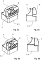
- the locking counterpart 4 mounted on a door leaf 2.1 is shown in different positions. Since the position of the locking counterpart 4 relative to the locking element 3 in the closed position also defines the position of the door leaf 2.1 in the door frame, the position of the door leaf 2.1 relative to the door frame in the closed position can also be set by adjusting the position of the locking counterpart 4.
- the locking counterpart 4 is not directly connected to the door leaf 2.1, but it is mounted on a carrier 7 which is connected to the door leaf 2.1.
- the carrier 7 has corresponding guides for the locking counterpart 4, in which the locking counterpart 4 can move relative to the carrier 7, as shown in FIG Figure 6a can be seen. The locking counterpart 4 can thus also be moved relative to the door leaf 2.1 via the carrier 7.
- Corresponding positioning can, for example, compensate for manufacturing and assembly tolerances.
- the contact pressure of the door or of the door leaf 2.1 on a seal arranged in the door frame can also be adjusted in this way. In the upper maximum position, the contact pressure would be significantly lower than in the lower maximum position.
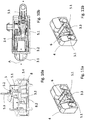
- FIG. 7 is that in Fig. 2 Housing 8 shown in a sectional view.
- a linearly movable slide 3.2 which can be moved back and forth in the radial direction R, is arranged in the housing 8.
- the slide 3.2 In the position shown, the slide 3.2 is in an end position in which the slide 3.2 rests against a stop on the housing 8. In this position it is therefore in accordance with the orientation of the illustration in Fig. 7 only possible to move the carriage 3.2 in the radial direction R upwards.
- the carriage 3.2 is in the in Fig. 7 position shown biased.
- this spring 5.2 is not shown in the figure, but it is located between the other stop of the housing 8 and the slide 3.2.
- the locking element 3 which can be moved in the axial direction A, is arranged in the slide 3.2.
- the carriage 3.2 has a corresponding guide 6 for the locking element 3, which enables axial movement.
- This guide 6 is also in the further Figures 8a, 9a and 10a easy to see, since the locking element 3 is not shown in these.
- the locking element 3 is biased by a spring 3.1 and can be moved in the axial direction A against the spring force into the housing 8 or into the slide 3.2.
- the dimensioning of the locking element 3 is such that a locking area 3.3 of the locking element 3 designed as a locking pin always protrudes from the housing 8.
- the housing 8 has a recess 8.2 designed as an elongated hole, which is also shown in the perspective view of FIG Fig. 2 is easy to see.
- the ends of this recess 8.2 form radial stops for the locking element 3 or for the above locking area 3.3 and to this extent limit the linear movement of the locking element 3 in the radial direction R.
- the locking area 3.3 of the locking element 3 plunges into the locking counterpart 4 or into the guide 6 of the locking counterpart 4, as is the case with regard to the FIGS. 1 to 4 has already been explained.
- the locking element 3 Due to the guide 6, the locking element 3 then moves back and forth in the housing 8 together with the slide 3.2 in the radial direction R. Furthermore, due to the configuration of the guide 6, the locking element 2 also moves in the axial direction A, which in view of the Fig. 12 will be explained in more detail.
- the locking element 2 In order to move the door leaf 2.1 into the closed position with respect to the door frame or to correspondingly open the door again, the locking element 2 must move in the radial direction R. By preventing a movement in the radial direction R, the door can also be prevented from being opened unintentionally. In order to reopen a closed door that has been locked in this way, the locking element 3 must first be released again before the door can then be opened via a "push".
- a door that is pre-locked in the closed position can be opened very easily via a "push"
- precautions must be taken to secure the door against unintentional opening, since in many situations such a simple door opening is not desired. For example, if a motor home drives into a tunnel at high speed, Due to the pressure forces acting on the outside of the mobile home, it can happen that doors arranged on the outside open automatically.
- a blocking device 5 cooperating with the locking element 3 is provided, with which the door can be locked in the pre-locked position.
- the blocking device 5 is described below with reference to FIGS. 8 to 10 described, in which the blocking device 5 is shown in various positions.
- the blocking device 5 is shown in a blocking position in which the slide 3.2 and thus also the locking element 3 cannot be moved in the radial direction R.
- the blocking device 5 has a blocking element 5.1 designed in the manner of a locking bolt, which can engage in a recess 3.4 of the slide 3.2 designed as a blind hole. Since the blocking device 5 or the blocking element 5.1 cannot be moved in the radial direction R, a movement of the carriage 3.2 in the radial direction R is blocked.
- the blocking element 5.1 In order to release the slide 3.2 again, the blocking element 5.1 must be pulled out of the slide 3.2 again.
- a motor drive is provided which, however, is not shown in the figures.
- the drive is connected to an external energy source via connection 8.3 and can be controlled accordingly.
- the blocking element 5.1 of the blocking device 5 is pretensioned in the direction of the blocking position via a spring 5.2. In order to transfer the blocking element 5.1 from the blocking position to the release position, it must be moved accordingly against the force of the spring 5.2. If the motor should fail and a movement of the locking element 3 is blocked, the door can only be opened again when the blocking element 5.1 has been pulled out of the slide 3.2. So that the door can still be opened even if the motor fails, the blocking device 5 has an emergency release 5.3, via which the carriage 3.2 can also be released again manually.
- the emergency release 5.3 is connected to the blocking element 5.1. Via this, the blocking element 5.1 can be moved against the force of the spring 5.2 and the carriage 3.2 can thus be released again.
- the emergency release 5.3 can be moved manually for this purpose via a cable pull, not shown in the figure.
- the blocking device 5 is not arranged in the housing 8, but in or on the locking counterpart 4.
- the corresponding locking counterpart 4 is in the Figures 11a and 11b shown.
- the blocking device 5 has two blocking elements 5.1, which can be moved into the guide 6 to block a movement of the locking element 3.
- the blocking position shown is therefore a movement of the locking area 3.3 of the locking element 3 prevented due to the blocking elements 5.1 and the door cannot be opened.
- the blocking elements 5.1 must release the guide 6 again so that the locking element 3 can then move in the guide 6 again.
- the locking counterpart 4 has a guide 6 in which the locking element 3 is guided during a relative movement between the door leaf 2.1 and the door frame.
- This guide 6 essentially consists of four different areas 6.1 to 6.4. According to the orientation of the Fig. 12 the release area 6.1 is arranged in the upper area of the guide 6.
- the door leaf 2.1 can be moved relative to the door frame. In this position, the door leaf 2.1 protrudes above the door frame, so that the door can be opened, for example, by a manual pulling movement or also by the force of a spring which supports the opening of the door.
- the locking element 3 can be transferred from the release area 6.1 into the closing area 6.2 via the run-up bevel 6.5.
- the locking element 3 moves in the axial direction A.
- the guide 6 also has a blocking area 6.3 in which the locking element 3 is arranged in a locking position.
- the guide 6 also has an opening area 6.4 which connects the blocking area 6.3 with the release area 6.1.
- the locking element 3 In the open position, the locking element 3 is initially in the release area 6.1 of the locking counterpart 4. In this position, the door can be moved in the opening direction and thus opened. To close the door, it and thus the locking element 3 are introduced into the closing area 6.2 via the run-up bevel 6.5. During this movement, the locking element 3 is moved in the recess 8.2. As soon as the locking element 3 has reached the lower end of the closing area 6.2, it moves further to the left into the blocking area 6.3 due to the spring 5.2 acting on the slide 3.2. The door can no longer be opened by pulling force in this position. The shell-shaped configuration of the contour of the guide 6 in the blocking area 6.3 ensures that the locking element 3 cannot move any further. The spring 5.2 acting on the slide 3.2 ensures that the locking element 3 or the locking area 3.3 according to the orientation of the Fig. 12 is pushed to the left.
- FIG Fig. 12 The design of the guide 6 and the functioning of the corresponding areas are shown in FIG Fig. 12 in connection with a blocking device 5 shown, which can be retracted into the guide 6, but they are not limited to this embodiment. Rather, that can be with regard to Fig. 12 described embodiment of the guide 6 can also be used when the blocking device 5 interacts with the carriage 3.2.
Landscapes
- Engineering & Computer Science (AREA)
- Mechanical Engineering (AREA)
- Lock And Its Accessories (AREA)
- Power-Operated Mechanisms For Wings (AREA)
Claims (10)
- Dispositif de fermeture pour une porte, notamment pour une porte d'une caravane ou d'un camping-car, pourvu d'un élément de verrouillage déplaçable (3) qui, dans la position fermée, s'engage dans une contrepartie de verrouillage (4) et pré-verrouille la porte, l'élément de verrouillage (3) et la contrepartie de verrouillage (4) étant configurés de telle sorte qu'ils coopèrent en tant que verrouillage push-push, et pourvu d'un dispositif de blocage (5), qui peut bloquer un déplacement de l'élément de verrouillage (3) pour le verrouillage principal de la porte, l'élément de verrouillage (3) étant déplaçable dans la direction radiale (R) et le dispositif de blocage (5) bloquant, dans la position de blocage, un déplacement radial de l'élément de verrouillage (3),
caractérisé en ce que
l'élément de verrouillage (3) est monté dans un chariot déplaçable (3.2), le dispositif de blocage (5) pouvant s'engager dans le chariot (3.2) et empêcher un déplacement de celui-ci pour le blocage de l'élément de verrouillage (3). - Dispositif selon la revendication 1, caractérisé en ce que le dispositif de blocage (5) forme une unité de construction avec l'élément de verrouillage (3).
- Dispositif selon l'une quelconque des revendications précédentes, caractérisé en ce que la contrepartie de verrouillage (4) comprend un guide (6) pour l'élément de verrouillage (3).
- Dispositif selon l'une quelconque des revendications précédentes, caractérisé en ce que l'élément de verrouillage (3) est déplaçable dans la direction axiale (A).
- Dispositif selon l'une quelconque des revendications précédentes, caractérisé par un boîtier (8), dans lequel l'élément de verrouillage (3) et le dispositif de blocage (5) sont montés.
- Dispositif selon l'une quelconque des revendications précédentes, caractérisé en ce que le dispositif de blocage (5) peut être déverrouillé d'urgence.
- Dispositif selon la revendication 6, caractérisé en ce que le dispositif de blocage (5) peut être déplacé hors de la position de blocage à l'encontre de la force d'un élément ressort pour le déverrouillage d'urgence.
- Dispositif selon l'une quelconque des revendications précédentes, caractérisé en ce que la contrepartie de verrouillage (4) est agencée sur un support (7) et peut être déplacée par rapport au support (7) pour l'ajustement de la position de la contrepartie de verrouillage (4).
- Porte pourvue d'un dispositif de verrouillage (1) selon l'une quelconque des revendications précédentes.
- Porte selon la revendication 9, caractérisée en ce que l'élément de verrouillage (3) est agencé sur le cadre de porte et la contrepartie de verrouillage (4) est agencée sur le panneau de porte (2.1).
Priority Applications (1)
| Application Number | Priority Date | Filing Date | Title |
|---|---|---|---|
| PL19191937T PL3617432T3 (pl) | 2018-08-23 | 2019-08-15 | Urządzenie zamykające do drzwi |
Applications Claiming Priority (1)
| Application Number | Priority Date | Filing Date | Title |
|---|---|---|---|
| DE102018120620.8A DE102018120620A1 (de) | 2018-08-23 | 2018-08-23 | Verschlussvorrichtung für eine Tür |
Publications (2)
| Publication Number | Publication Date |
|---|---|
| EP3617432A1 EP3617432A1 (fr) | 2020-03-04 |
| EP3617432B1 true EP3617432B1 (fr) | 2021-12-22 |
Family
ID=67658984
Family Applications (1)
| Application Number | Title | Priority Date | Filing Date |
|---|---|---|---|
| EP19191937.2A Active EP3617432B1 (fr) | 2018-08-23 | 2019-08-15 | Dispositif de fermeture pour une porte |
Country Status (4)
| Country | Link |
|---|---|
| EP (1) | EP3617432B1 (fr) |
| DE (1) | DE102018120620A1 (fr) |
| ES (1) | ES2907853T3 (fr) |
| PL (1) | PL3617432T3 (fr) |
Cited By (1)
| Publication number | Priority date | Publication date | Assignee | Title |
|---|---|---|---|---|
| DE102023101547A1 (de) * | 2023-01-23 | 2024-07-25 | Emka Beschlagteile Gmbh & Co. Kg | Verschlussvorrichtung |
Family Cites Families (9)
| Publication number | Priority date | Publication date | Assignee | Title |
|---|---|---|---|---|
| DE3915362A1 (de) * | 1988-10-26 | 1990-05-03 | Franzen Soehne S | Schloss, insbesondere fuer moebel bzw. vitrinen |
| DE19711331C5 (de) * | 1997-03-18 | 2012-06-14 | Bayerische Motoren Werke Aktiengesellschaft | Vorrichtung zum Öffnen und Verriegeln einer Kraftfahrzeug-Tankklappe |
| FR2930201B1 (fr) * | 2008-04-18 | 2010-04-23 | Coutier Moulage Gen Ind | Trappe a carburant verrouillable pour vehicule automobile. |
| IT1397541B1 (it) * | 2010-01-14 | 2013-01-16 | Zadi S P A | Dispositivo di bloccaggio, in particolare di tipo "push-push". |
| DE102010050800A1 (de) * | 2010-11-09 | 2012-05-10 | Audi Ag | Verriegelungseinrichtung mit einer Push-Push-Mechanik für einen zwischen einer Schließ- und Offenstellung betätigbaren Behälter oder Deckel, insbesondere von Kraftfahrzeugen |
| DE102011116067A1 (de) * | 2011-07-22 | 2013-01-24 | Kiekert Ag | Tankklappenverriegelung mit reduzierter Anzahl von Bauteilen |
| DE102014106846B4 (de) * | 2013-05-16 | 2022-02-17 | GM Global Technology Operations LLC (n. d. Gesetzen des Staates Delaware) | Push-Push-Verriegelung |
| WO2015022106A1 (fr) * | 2013-08-14 | 2015-02-19 | Dr. Schneider Kunststoffwerke Gmbh | Dispositif pourvu d'un mécanisme « push-push » |
| EP3287579B1 (fr) * | 2016-08-26 | 2022-10-12 | EMKA BESCHLAGTEILE GmbH & Co. KG | Dispositif de fermeture pour porte |
-
2018
- 2018-08-23 DE DE102018120620.8A patent/DE102018120620A1/de not_active Withdrawn
-
2019
- 2019-08-15 ES ES19191937T patent/ES2907853T3/es active Active
- 2019-08-15 EP EP19191937.2A patent/EP3617432B1/fr active Active
- 2019-08-15 PL PL19191937T patent/PL3617432T3/pl unknown
Cited By (1)
| Publication number | Priority date | Publication date | Assignee | Title |
|---|---|---|---|---|
| DE102023101547A1 (de) * | 2023-01-23 | 2024-07-25 | Emka Beschlagteile Gmbh & Co. Kg | Verschlussvorrichtung |
Also Published As
| Publication number | Publication date |
|---|---|
| ES2907853T3 (es) | 2022-04-26 |
| PL3617432T3 (pl) | 2022-03-28 |
| EP3617432A1 (fr) | 2020-03-04 |
| DE102018120620A1 (de) | 2020-02-27 |
Similar Documents
| Publication | Publication Date | Title |
|---|---|---|
| EP3612697B1 (fr) | Serrure pour véhicule à moteur | |
| WO2015139678A1 (fr) | Dispositif de fermeture pour un capot de véhicule automobile | |
| DE102014226981A1 (de) | Schwenkschiebetür-Verriegelungsvorrichtung und Schwenkschiebetür-System | |
| EP3464764B1 (fr) | Serrure de véhicule automobile | |
| DE102017129427B3 (de) | Scharnierverschluss | |
| EP1717392A2 (fr) | Arrangement de serrure supplémentaire pour porte coulissante de véhicule automobile | |
| EP2291571A1 (fr) | Dispositif de fermeture comprenant un ressort à cliquet | |
| EP1947274B1 (fr) | Dispositif d'entraînement pour une ferrure de bielle | |
| DD219985A5 (de) | Ausschwingtuer mit betaetigungseinrichtung | |
| DE102012009414A1 (de) | Frontklappenschloss für eine Fahrzeug-Frontklappe mit Fußgängerschutzstellung | |
| EP2540616B1 (fr) | Mécanisme de fermeture pour portes coulissantes assistées | |
| EP3287579B1 (fr) | Dispositif de fermeture pour porte | |
| EP3847328B1 (fr) | Unité d'entraînement pour des applications en automobile | |
| EP3247854B1 (fr) | Porte comprenant un entraînement de porte avec un entraînement principal et un entraînement auxiliaire et éléments fonctionnels supplémentaires | |
| EP3617432A1 (fr) | Dispositif de fermeture pour une porte | |
| EP2410113B1 (fr) | Verrouillage de protection anti-mines et procédé de déverrouillage du verrouillage de protection anti-mines | |
| DE102016100956A1 (de) | Türantrieb mit Haupt- und Hilfsantrieb und Zusatzfunktionskomponenten | |
| EP2835487A1 (fr) | Dispositif de battant d'un bâtiment | |
| DE102013114180A1 (de) | Kraftfahrzeugtürverschluss | |
| DE102012200640A1 (de) | Antriebsvorrichtung für eine gemeinsame Betätigung eines Zentralverschlusses und des Flügels eines Fensters oder einer Türe | |
| EP2199729A2 (fr) | Couvercle de trou d'homme pivotant, en particulier pour véhicules militaires | |
| DE10200153A1 (de) | Elektromotorische Verriegelungsvorrichtung für Möbel | |
| EP2746506B1 (fr) | Serrure de déclenchement | |
| DE102020112147A1 (de) | Scharnierbaugruppe mit gemeinsamer Betätigung | |
| EP3744932B1 (fr) | Fermeture à crémone à déverrouillage de secours |
Legal Events
| Date | Code | Title | Description |
|---|---|---|---|
| PUAI | Public reference made under article 153(3) epc to a published international application that has entered the european phase |
Free format text: ORIGINAL CODE: 0009012 |
|
| STAA | Information on the status of an ep patent application or granted ep patent |
Free format text: STATUS: THE APPLICATION HAS BEEN PUBLISHED |
|
| AK | Designated contracting states |
Kind code of ref document: A1 Designated state(s): AL AT BE BG CH CY CZ DE DK EE ES FI FR GB GR HR HU IE IS IT LI LT LU LV MC MK MT NL NO PL PT RO RS SE SI SK SM TR |
|
| AX | Request for extension of the european patent |
Extension state: BA ME |
|
| STAA | Information on the status of an ep patent application or granted ep patent |
Free format text: STATUS: REQUEST FOR EXAMINATION WAS MADE |
|
| 17P | Request for examination filed |
Effective date: 20200904 |
|
| RBV | Designated contracting states (corrected) |
Designated state(s): AL AT BE BG CH CY CZ DE DK EE ES FI FR GB GR HR HU IE IS IT LI LT LU LV MC MK MT NL NO PL PT RO RS SE SI SK SM TR |
|
| STAA | Information on the status of an ep patent application or granted ep patent |
Free format text: STATUS: EXAMINATION IS IN PROGRESS |
|
| 17Q | First examination report despatched |
Effective date: 20201211 |
|
| GRAP | Despatch of communication of intention to grant a patent |
Free format text: ORIGINAL CODE: EPIDOSNIGR1 |
|
| STAA | Information on the status of an ep patent application or granted ep patent |
Free format text: STATUS: GRANT OF PATENT IS INTENDED |
|
| INTG | Intention to grant announced |
Effective date: 20210720 |
|
| GRAS | Grant fee paid |
Free format text: ORIGINAL CODE: EPIDOSNIGR3 |
|
| GRAA | (expected) grant |
Free format text: ORIGINAL CODE: 0009210 |
|
| STAA | Information on the status of an ep patent application or granted ep patent |
Free format text: STATUS: THE PATENT HAS BEEN GRANTED |
|
| AK | Designated contracting states |
Kind code of ref document: B1 Designated state(s): AL AT BE BG CH CY CZ DE DK EE ES FI FR GB GR HR HU IE IS IT LI LT LU LV MC MK MT NL NO PL PT RO RS SE SI SK SM TR |
|
| RAP3 | Party data changed (applicant data changed or rights of an application transferred) |
Owner name: EMKA BESCHLAGTEILE GMBH & CO. KG |
|
| REG | Reference to a national code |
Ref country code: GB Ref legal event code: FG4D Free format text: NOT ENGLISH |
|
| REG | Reference to a national code |
Ref country code: CH Ref legal event code: EP |
|
| REG | Reference to a national code |
Ref country code: DE Ref legal event code: R096 Ref document number: 502019003048 Country of ref document: DE |
|
| REG | Reference to a national code |
Ref country code: AT Ref legal event code: REF Ref document number: 1457197 Country of ref document: AT Kind code of ref document: T Effective date: 20220115 |
|
| REG | Reference to a national code |
Ref country code: IE Ref legal event code: FG4D Free format text: LANGUAGE OF EP DOCUMENT: GERMAN |
|
| REG | Reference to a national code |
Ref country code: SE Ref legal event code: TRGR |
|
| REG | Reference to a national code |
Ref country code: LT Ref legal event code: MG9D |
|
| REG | Reference to a national code |
Ref country code: ES Ref legal event code: FG2A Ref document number: 2907853 Country of ref document: ES Kind code of ref document: T3 Effective date: 20220426 |
|
| PG25 | Lapsed in a contracting state [announced via postgrant information from national office to epo] |
Ref country code: RS Free format text: LAPSE BECAUSE OF FAILURE TO SUBMIT A TRANSLATION OF THE DESCRIPTION OR TO PAY THE FEE WITHIN THE PRESCRIBED TIME-LIMIT Effective date: 20211222 Ref country code: LT Free format text: LAPSE BECAUSE OF FAILURE TO SUBMIT A TRANSLATION OF THE DESCRIPTION OR TO PAY THE FEE WITHIN THE PRESCRIBED TIME-LIMIT Effective date: 20211222 Ref country code: FI Free format text: LAPSE BECAUSE OF FAILURE TO SUBMIT A TRANSLATION OF THE DESCRIPTION OR TO PAY THE FEE WITHIN THE PRESCRIBED TIME-LIMIT Effective date: 20211222 Ref country code: BG Free format text: LAPSE BECAUSE OF FAILURE TO SUBMIT A TRANSLATION OF THE DESCRIPTION OR TO PAY THE FEE WITHIN THE PRESCRIBED TIME-LIMIT Effective date: 20220322 |
|
| REG | Reference to a national code |
Ref country code: NL Ref legal event code: MP Effective date: 20211222 |
|
| PG25 | Lapsed in a contracting state [announced via postgrant information from national office to epo] |
Ref country code: NO Free format text: LAPSE BECAUSE OF FAILURE TO SUBMIT A TRANSLATION OF THE DESCRIPTION OR TO PAY THE FEE WITHIN THE PRESCRIBED TIME-LIMIT Effective date: 20220322 Ref country code: LV Free format text: LAPSE BECAUSE OF FAILURE TO SUBMIT A TRANSLATION OF THE DESCRIPTION OR TO PAY THE FEE WITHIN THE PRESCRIBED TIME-LIMIT Effective date: 20211222 Ref country code: HR Free format text: LAPSE BECAUSE OF FAILURE TO SUBMIT A TRANSLATION OF THE DESCRIPTION OR TO PAY THE FEE WITHIN THE PRESCRIBED TIME-LIMIT Effective date: 20211222 Ref country code: GR Free format text: LAPSE BECAUSE OF FAILURE TO SUBMIT A TRANSLATION OF THE DESCRIPTION OR TO PAY THE FEE WITHIN THE PRESCRIBED TIME-LIMIT Effective date: 20220323 |
|
| PG25 | Lapsed in a contracting state [announced via postgrant information from national office to epo] |
Ref country code: NL Free format text: LAPSE BECAUSE OF FAILURE TO SUBMIT A TRANSLATION OF THE DESCRIPTION OR TO PAY THE FEE WITHIN THE PRESCRIBED TIME-LIMIT Effective date: 20211222 |
|
| PG25 | Lapsed in a contracting state [announced via postgrant information from national office to epo] |
Ref country code: SM Free format text: LAPSE BECAUSE OF FAILURE TO SUBMIT A TRANSLATION OF THE DESCRIPTION OR TO PAY THE FEE WITHIN THE PRESCRIBED TIME-LIMIT Effective date: 20211222 Ref country code: SK Free format text: LAPSE BECAUSE OF FAILURE TO SUBMIT A TRANSLATION OF THE DESCRIPTION OR TO PAY THE FEE WITHIN THE PRESCRIBED TIME-LIMIT Effective date: 20211222 Ref country code: RO Free format text: LAPSE BECAUSE OF FAILURE TO SUBMIT A TRANSLATION OF THE DESCRIPTION OR TO PAY THE FEE WITHIN THE PRESCRIBED TIME-LIMIT Effective date: 20211222 Ref country code: PT Free format text: LAPSE BECAUSE OF FAILURE TO SUBMIT A TRANSLATION OF THE DESCRIPTION OR TO PAY THE FEE WITHIN THE PRESCRIBED TIME-LIMIT Effective date: 20220422 Ref country code: EE Free format text: LAPSE BECAUSE OF FAILURE TO SUBMIT A TRANSLATION OF THE DESCRIPTION OR TO PAY THE FEE WITHIN THE PRESCRIBED TIME-LIMIT Effective date: 20211222 Ref country code: CZ Free format text: LAPSE BECAUSE OF FAILURE TO SUBMIT A TRANSLATION OF THE DESCRIPTION OR TO PAY THE FEE WITHIN THE PRESCRIBED TIME-LIMIT Effective date: 20211222 |
|
| REG | Reference to a national code |
Ref country code: DE Ref legal event code: R097 Ref document number: 502019003048 Country of ref document: DE |
|
| PG25 | Lapsed in a contracting state [announced via postgrant information from national office to epo] |
Ref country code: IS Free format text: LAPSE BECAUSE OF FAILURE TO SUBMIT A TRANSLATION OF THE DESCRIPTION OR TO PAY THE FEE WITHIN THE PRESCRIBED TIME-LIMIT Effective date: 20220422 |
|
| PLBE | No opposition filed within time limit |
Free format text: ORIGINAL CODE: 0009261 |
|
| STAA | Information on the status of an ep patent application or granted ep patent |
Free format text: STATUS: NO OPPOSITION FILED WITHIN TIME LIMIT |
|
| PG25 | Lapsed in a contracting state [announced via postgrant information from national office to epo] |
Ref country code: DK Free format text: LAPSE BECAUSE OF FAILURE TO SUBMIT A TRANSLATION OF THE DESCRIPTION OR TO PAY THE FEE WITHIN THE PRESCRIBED TIME-LIMIT Effective date: 20211222 Ref country code: AL Free format text: LAPSE BECAUSE OF FAILURE TO SUBMIT A TRANSLATION OF THE DESCRIPTION OR TO PAY THE FEE WITHIN THE PRESCRIBED TIME-LIMIT Effective date: 20211222 |
|
| 26N | No opposition filed |
Effective date: 20220923 |
|
| PG25 | Lapsed in a contracting state [announced via postgrant information from national office to epo] |
Ref country code: SI Free format text: LAPSE BECAUSE OF FAILURE TO SUBMIT A TRANSLATION OF THE DESCRIPTION OR TO PAY THE FEE WITHIN THE PRESCRIBED TIME-LIMIT Effective date: 20211222 |
|
| PG25 | Lapsed in a contracting state [announced via postgrant information from national office to epo] |
Ref country code: MC Free format text: LAPSE BECAUSE OF FAILURE TO SUBMIT A TRANSLATION OF THE DESCRIPTION OR TO PAY THE FEE WITHIN THE PRESCRIBED TIME-LIMIT Effective date: 20211222 |
|
| PG25 | Lapsed in a contracting state [announced via postgrant information from national office to epo] |
Ref country code: LU Free format text: LAPSE BECAUSE OF NON-PAYMENT OF DUE FEES Effective date: 20220815 |
|
| REG | Reference to a national code |
Ref country code: BE Ref legal event code: MM Effective date: 20220831 |
|
| P01 | Opt-out of the competence of the unified patent court (upc) registered |
Effective date: 20230519 |
|
| PG25 | Lapsed in a contracting state [announced via postgrant information from national office to epo] |
Ref country code: IE Free format text: LAPSE BECAUSE OF NON-PAYMENT OF DUE FEES Effective date: 20220815 |
|
| PG25 | Lapsed in a contracting state [announced via postgrant information from national office to epo] |
Ref country code: BE Free format text: LAPSE BECAUSE OF NON-PAYMENT OF DUE FEES Effective date: 20220831 |
|
| PG25 | Lapsed in a contracting state [announced via postgrant information from national office to epo] |
Ref country code: HU Free format text: LAPSE BECAUSE OF FAILURE TO SUBMIT A TRANSLATION OF THE DESCRIPTION OR TO PAY THE FEE WITHIN THE PRESCRIBED TIME-LIMIT; INVALID AB INITIO Effective date: 20190815 |
|
| PG25 | Lapsed in a contracting state [announced via postgrant information from national office to epo] |
Ref country code: CY Free format text: LAPSE BECAUSE OF FAILURE TO SUBMIT A TRANSLATION OF THE DESCRIPTION OR TO PAY THE FEE WITHIN THE PRESCRIBED TIME-LIMIT Effective date: 20211222 |
|
| PG25 | Lapsed in a contracting state [announced via postgrant information from national office to epo] |
Ref country code: MK Free format text: LAPSE BECAUSE OF FAILURE TO SUBMIT A TRANSLATION OF THE DESCRIPTION OR TO PAY THE FEE WITHIN THE PRESCRIBED TIME-LIMIT Effective date: 20211222 |
|
| PG25 | Lapsed in a contracting state [announced via postgrant information from national office to epo] |
Ref country code: MT Free format text: LAPSE BECAUSE OF FAILURE TO SUBMIT A TRANSLATION OF THE DESCRIPTION OR TO PAY THE FEE WITHIN THE PRESCRIBED TIME-LIMIT Effective date: 20211222 |
|
| PGFP | Annual fee paid to national office [announced via postgrant information from national office to epo] |
Ref country code: DE Payment date: 20240831 Year of fee payment: 6 |
|
| PGFP | Annual fee paid to national office [announced via postgrant information from national office to epo] |
Ref country code: GB Payment date: 20240822 Year of fee payment: 6 |
|
| PGFP | Annual fee paid to national office [announced via postgrant information from national office to epo] |
Ref country code: FR Payment date: 20240814 Year of fee payment: 6 |
|
| PGFP | Annual fee paid to national office [announced via postgrant information from national office to epo] |
Ref country code: CH Payment date: 20240901 Year of fee payment: 6 Ref country code: ES Payment date: 20240918 Year of fee payment: 6 |
|
| PGFP | Annual fee paid to national office [announced via postgrant information from national office to epo] |
Ref country code: AT Payment date: 20240819 Year of fee payment: 6 |
|
| PGFP | Annual fee paid to national office [announced via postgrant information from national office to epo] |
Ref country code: PL Payment date: 20240805 Year of fee payment: 6 |
|
| PGFP | Annual fee paid to national office [announced via postgrant information from national office to epo] |
Ref country code: SE Payment date: 20240821 Year of fee payment: 6 Ref country code: IT Payment date: 20240830 Year of fee payment: 6 |
|
| PGFP | Annual fee paid to national office [announced via postgrant information from national office to epo] |
Ref country code: TR Payment date: 20240807 Year of fee payment: 6 |
|
| REG | Reference to a national code |
Ref country code: DE Ref legal event code: R119 Ref document number: 502019003048 Country of ref document: DE |
|
| REG | Reference to a national code |
Ref country code: CH Ref legal event code: H13 Free format text: ST27 STATUS EVENT CODE: U-0-0-H10-H13 (AS PROVIDED BY THE NATIONAL OFFICE) Effective date: 20260324 |
|
| PG25 | Lapsed in a contracting state [announced via postgrant information from national office to epo] |
Ref country code: AT Free format text: LAPSE BECAUSE OF NON-PAYMENT OF DUE FEES Effective date: 20250815 |
|
| REG | Reference to a national code |
Ref country code: AT Ref legal event code: MM01 Ref document number: 1457197 Country of ref document: AT Kind code of ref document: T Effective date: 20250815 |
|
| PG25 | Lapsed in a contracting state [announced via postgrant information from national office to epo] |
Ref country code: CH Free format text: LAPSE BECAUSE OF NON-PAYMENT OF DUE FEES Effective date: 20250831 |
|
| GBPC | Gb: european patent ceased through non-payment of renewal fee |
Effective date: 20250815 |