EP3465131B1 - Verfahren zur dynamometrischen prüfung eines kraftfahrzeuges - Google Patents
Verfahren zur dynamometrischen prüfung eines kraftfahrzeuges Download PDFInfo
- Publication number
- EP3465131B1 EP3465131B1 EP17807113.0A EP17807113A EP3465131B1 EP 3465131 B1 EP3465131 B1 EP 3465131B1 EP 17807113 A EP17807113 A EP 17807113A EP 3465131 B1 EP3465131 B1 EP 3465131B1
- Authority
- EP
- European Patent Office
- Prior art keywords
- vehicle
- adapter plate
- wheel
- dynamometer
- test unit
- Prior art date
- Legal status (The legal status is an assumption and is not a legal conclusion. Google has not performed a legal analysis and makes no representation as to the accuracy of the status listed.)
- Active
Links
Images


Classifications
-
- G—PHYSICS
- G01—MEASURING; TESTING
- G01M—TESTING STATIC OR DYNAMIC BALANCE OF MACHINES OR STRUCTURES; TESTING OF STRUCTURES OR APPARATUS, NOT OTHERWISE PROVIDED FOR
- G01M17/00—Testing of vehicles
- G01M17/007—Wheeled or endless-tracked vehicles
-
- G—PHYSICS
- G01—MEASURING; TESTING
- G01L—MEASURING FORCE, STRESS, TORQUE, WORK, MECHANICAL POWER, MECHANICAL EFFICIENCY, OR FLUID PRESSURE
- G01L3/00—Measuring torque, work, mechanical power, or mechanical efficiency, in general
- G01L3/16—Rotary-absorption dynamometers, e.g. of brake type
- G01L3/20—Rotary-absorption dynamometers, e.g. of brake type fluid actuated
-
- G—PHYSICS
- G01—MEASURING; TESTING
- G01M—TESTING STATIC OR DYNAMIC BALANCE OF MACHINES OR STRUCTURES; TESTING OF STRUCTURES OR APPARATUS, NOT OTHERWISE PROVIDED FOR
- G01M15/00—Testing of engines
-
- G—PHYSICS
- G01—MEASURING; TESTING
- G01M—TESTING STATIC OR DYNAMIC BALANCE OF MACHINES OR STRUCTURES; TESTING OF STRUCTURES OR APPARATUS, NOT OTHERWISE PROVIDED FOR
- G01M15/00—Testing of engines
- G01M15/04—Testing internal-combustion engines
- G01M15/042—Testing internal-combustion engines by monitoring a single specific parameter not covered by groups G01M15/06 - G01M15/12
- G01M15/044—Testing internal-combustion engines by monitoring a single specific parameter not covered by groups G01M15/06 - G01M15/12 by monitoring power, e.g. by operating the engine with one of the ignitions interrupted; by using acceleration tests
-
- G—PHYSICS
- G01—MEASURING; TESTING
- G01M—TESTING STATIC OR DYNAMIC BALANCE OF MACHINES OR STRUCTURES; TESTING OF STRUCTURES OR APPARATUS, NOT OTHERWISE PROVIDED FOR
- G01M17/00—Testing of vehicles
-
- G—PHYSICS
- G01—MEASURING; TESTING
- G01M—TESTING STATIC OR DYNAMIC BALANCE OF MACHINES OR STRUCTURES; TESTING OF STRUCTURES OR APPARATUS, NOT OTHERWISE PROVIDED FOR
- G01M17/00—Testing of vehicles
- G01M17/007—Wheeled or endless-tracked vehicles
- G01M17/0072—Wheeled or endless-tracked vehicles the wheels of the vehicle co-operating with rotatable rolls
-
- G—PHYSICS
- G01—MEASURING; TESTING
- G01M—TESTING STATIC OR DYNAMIC BALANCE OF MACHINES OR STRUCTURES; TESTING OF STRUCTURES OR APPARATUS, NOT OTHERWISE PROVIDED FOR
- G01M17/00—Testing of vehicles
- G01M17/007—Wheeled or endless-tracked vehicles
- G01M17/0072—Wheeled or endless-tracked vehicles the wheels of the vehicle co-operating with rotatable rolls
- G01M17/0074—Details, e.g. roller construction, vehicle restraining devices
Definitions
- This invention relates to dynamometer testing of vehicles, and in particular to a method for use when dynamometer testing vehicles having at least one wheel shaft and a power source for applying power to said first wheel shaft.
- Dynamometer testing of vehicles is known per se, and can, for example, be carried out by roller type (rolling road) dynamometers equipped with large rollers that support the vehicle wheels, and which are used to apply a brake torque to the drive wheels of the vehicle.
- roller type (rolling road) dynamometers equipped with large rollers that support the vehicle wheels, and which are used to apply a brake torque to the drive wheels of the vehicle.
- Such systems are not always capable of providing the desired measurement accuracy and/or freedom of measurement.
- vehicle transmissions are becoming increasingly complex, and may include various kinds of power sources for providing power to wheel shafts of the vehicle. These power sources can be arranged to provide propelling powers, but also braking powers, e.g. when used for regenerative braking.
- the increased complexity of vehicle transmissions provides corresponding challenges for dynamometer testing systems.
- DE 4136508 A1 discloses a motor vehicle test bench with a wheel coupling having a rotating center rotating with the wheel shaft, the wheel coupling being stationary during testing for vehicle support.
- DE 10 2010 016587 A1 discloses a test arrangement for testing a motor vehicle while the tyres are stationary.
- AT 512 006 A1 also discloses a test arrangement for testing a motor vehicle while the tyres are stationary.
- vehicle dynamometer systems of the kind described above i.e. systems where dynamometer test units comprising a dynamometer power source are connected to the wheel shafts of a vehicle are capable of providing accurate measurement results when testing vehicles. For example, vehicles can be tested during rapid accelerations, and wheel torque throughout the vehicle engine speed range can be measured in an accurate manner.
- a substantial amount of waiting time may be required between tests in order to allow the vehicle to cool down to a desired extent.
- the same vehicle may be set up for testing a large number of times to obtain a total desired accumulated testing time. Since it may take a substantial amount of time for the vehicle to cool off to a desired degree or to be cooled down to a desired temperature, or when the vehicle otherwise is subject to a number of repetitive tests, it is in general required that the vehicle is disconnected from and moved away from testing equipment in order to allow testing of another vehicle using the dynamometer test system in the meantime, e.g. to thereby obtain a higher level of utilization of the dynamometer test system.
- Such relocation of the vehicle require that the vehicle is disconnected from the dynamometer test units and the wheels remounted to the wheel shafts.
- at least two dynamometer test units are used, i.e. one dynamometer test unit for each half shaft (left and right) of a front wheel axle or a rear wheel axle.
- dynamometer test units may be connected to each wheel shaft. This may, however, be the case not only in regard of all-wheel-drive vehicles but also for vehicles where only one axle contains drive wheels but where it may be required or desirable to set also non-driven wheels in rotation during testing.
- the dynamometer test units must be disconnected so that the vehicle wheels can be remounted to the vehicle in order to allow relocation of the vehicle pending an upcoming test during which waiting time other vehicles may be tested.
- the present invention provides a method for facilitating such relocation of the vehicle.
- this is accomplished through the use of an adapter plate which is arranged to be fixed to the wheel shaft, e.g. through the use of fixing means such as wheel fasteners, e.g. wheel nuts, bolts, lugs, and/or studs, being used to secure the wheel to the wheel hub.
- the adapter plate can be arranged to be rigidly coupled to the wheel shaft, or at least in a rotationally fixed manner to rotate with the wheel shaft.
- the adapter plate may comprise holes corresponding to the particular lug/stud pattern being used, and be attached to the wheel hub.
- the adapter plate may be provided with e.g. slots to allow a single adapter plate to be used for a plurality of lug/stud patterns.
- the adapter plate can further be arranged to fixedly connected to an output shaft of a dynamometer test unit to thereby couple the output shaft of the dynamometer test unit to the wheel shaft of the vehicle being tested, so that during testing, the wheel shaft rotates with the output shaft of the dynamometer test unit.
- This can be accomplished, for example by means of e.g. a flanged being rigidly attached to, or forming part of an output shaft of the dynamometer test unit so that the adapter plate and dynamometer test unit can be coupled together using suitable fasteners.
- the adapter plate is arranged to be connected to wheel hub and/or dynamometer test unit by means of any other suitable means.
- spline couplings may be used to obtain a rotationally fixed coupling between adapter plate and wheel hub and/or dynamometer test unit.
- Such coupling may be advantageous e.g. regarding the coupling between adapter plate and dynamometer test unit.
- the dynamometer test unit may comprise a male/female part of a spline coupling that is arranged to engage with a corresponding female/male part of the adapter plate, where the dynamometer test unit may be arranged to, when the vehicle is in position for testing, be maneuvered to engage with the corresponding splines part of the adapter plate.
- the dynamometer test unit may e.g. be secured from movement in axial direction to ensure a maintained rotationally fixed coupling throughout the test.
- the adapter plate in addition, is designed such that, when still being secured to the wheel shaft but being released from the dynamometer test unit, the adapter plate supports the vehicle by taking the place of the wheel to allow for relocation of the vehicle pending a further test. In this way, the vehicle can be relocated supported by the adapter plate so that the removed vehicle wheels need not be remounted between tests. Hence the vehicle can be supported by the adapter plate the time that lapses between tests of the vehicle.
- the adapter plate can be manufactured from any suitable metal such as a metal, e.g. aluminum or steel, or, for example, from a composite material, or any other suitable material, such as a ceramic material.
- a material providing galvanic isolation, or the coupling otherwise providing galvanic isolation between wheel hub and dynamometer test unit may be advantageous, e.g. to avoid earthing of the vehicle through the dynamometer test unit. Such earthing may render problems e.g. when simultaneously charging and testing an electric vehicle.
- the design of the adapter plate may be solid apart from suitable means such as holes and/or slots for allowing attachment according to the above, but the adapter plates may also be of any suitable design for as long as a desired weight can be supported.
- the adapter plate may be of a spoke design.
- the adapter plate is designed to carry at least a weight normally being carried by a vehicle wheel, e.g. a weight in the range 250-1000 kg for a passenger car.
- the adapter plate may be designed with a diameter ensuring a non-negative, i.e. positive belly clearance for all or a plurality of vehicles such as passenger cars being subjected to tests to allow relocation. Oftentimes relocation is performed indoors and/or on level surfaces such as floors so that only a very small belly clearance is required in comparison to belly clearance required in real life driving. Hence, the adapter plate need only provide a clearance sufficient to accomplish the desired relocation of the vehicle. Furthermore, the vehicles need not be relocated by being powered by the vehicle engine, but the vehicles may instead be relocated using e.g. specially designed vehicle movers. Such vehicle movers are known to the person skilled in the art. Naturally, relocation by human force is also possible.
- the adapter plate may be designed to have a diameter substantially corresponding to the wheel diameter normally being used on the vehicle, or a diameter that provides desired functionality for most or all vehicles. In this way, the same or substantially the same belly clearance can be ensured, or at least a sufficient belly clearance.
- the diameter of the adapter plate is at least 450 mm since in general at least this diameter is required to ensure that a sufficient belly clearance is obtained.
- the adapter plate has any diameter in the interval 500 mm to 750 mm.
- the adapter plate has any diameter in the interval 250 mm to 800 mm.
- the outer circumference may be provided with a layer of a softer and/or higher-friction material, such as e.g. rubber/rubber composition to improve maneuverability and/or reduce sound and/or wear on the surface on which the vehicle is present when relocating the vehicle.
- a layer of any other suitable material such as e.g. polyurethane, may be used.
- the method also includes:
- a method that allow for relocation of the vehicle without the need for remounting the actual vehicle wheels.
- a vehicle that has been subjected to one test can be relocated to a suitable area pending a further test, and when the vehicle again is to be tested the time for setting up the test can be significantly reduced since the adapter plates are already attached to the vehicle and ready to be fixedly connected to the dynamometer test units. In this way substantial amounts of time and effort can be saved.
- adapter plates when testing vehicles, adapter plates may be selected not only on the basis e.g. of radius to support the vehicle when relocating the vehicle, but adapter plates of different weights may also be provided e.g. to allow testing using a desired moment of inertia of dynamometer test unit and/or wheel shaft. In this way, e.g. torsional oscillations/vibrations in the powertrain can be tested and/or real life driving on roads and/or tyre-to-road interaction be tested with high accuracy.
- the adapter plate can hence be selected e.g. to obtain desired and different testing conditions, where the adapter plate can be selected so that the dynamometer test unit mimics the wheel with high accuracy, but where heavier adapter plates can be used e.g. to further evaluate torsional vibrations in the powertrain.
- hub centering rings may be utilized in a manner similar to when used with wheel rims to facilitate centering the adapter plate to the wheel hub.
- the method according to the invention can be performed in a vehicle dynamometer system
- the dynamometer test units are of any suitable kind, e.g. having an electrical machine and/or hydraulic pump as power source for applying power to a wheel shaft being tested.
- the dynamometer test unit may be of a kind having two (or more) dynamometer power sources for providing power to a same wheel shaft of the vehicle, where one of said power sources can be an electrical machine.
- the dynamometer test unit is designed for testing passenger cars.
- the invention is also suitable for use in dynamometer testing of motorcycles having two or more wheels, where the wheels are attached to the motorcycle in a car-like manner, which is becoming increasingly common. In case of motorcycles, it may often be sufficient that only one wheel (wheel shaft) is connected to a dynamometer test unit.
- the dynamometer test unit may be designed such that connection to the adapter plate while the vehicle is supported by the adapter plate(s) is possible, and where, when connected to the adapter plate, the dynamometer test unit may be raised, e.g. through the use of built-in lifting means, to clear the adapter plate(s) from the floor while simultaneously supporting the weight of the vehicle.
- Fig. 1 discloses a vehicle 100 set up for being tested with a vehicle dynamometer system in a method according to the present invention.
- the vehicle 100 is a two-wheel drive vehicle, and includes front axle wheel shafts, or half shafts 105, 106, and rear axle wheel shafts 112, 113.
- the wheels of the vehicle 100 are not shown due to the vehicle being set up for dynamometer testing.
- the disclosed vehicle 100 includes a drive train, which includes a power source such as a combustion engine 101 which is connected to a gearbox 102.
- the gearbox 102 can be of any suitable kind and, e.g., consist of a manual transmission or an automatic transmission.
- the front axle wheel (half) shafts 105, 106 extend from the gear box to the front axle wheels of the vehicle 100.
- a vehicle dynamometer system is connected to the vehicle 100, and includes dynamometer test units 110, 111.
- the dynamometer test units 110, 111 are connected to a measuring and control system 114, such as e.g. a computer with associated display 115, by means of which the tests are controlled, and by means of which an operator of the system can initiate tests and provide necessary information for performing the dynamometer tests.
- the two test units 110, 111 are basically identical and operate in the same way.
- the measuring and control system 114 transmits control signals to the dynamometer test units to request desired load (torque) and rotational speed. Torque and rotational speed can be measured in different ways, as explained below.
- the dynamometer test units 110-111 can consist of substantially identical test units, and are described more in detail in fig 2 .
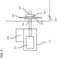
- Fig. 2 shows an example of the set-up for one half shaft more in detail.
- Each dynamometer test unit 110, 111 includes a dynamometer in the form of a power source assembly, e.g. comprising one or more hydrostatic pumps 201.
- the power source assembly is further provided with means for measuring the torque applied to an output shaft 202 of the test unit 111.
- the use of a hydrostatic pump assembly as power-absorbing means in the dynamometer is only exemplary.
- the invention can also be realized with other types of power-absorbing means.
- an electrical machine may be utilized as power source of a test unit 111 to apply torque to the wheel shaft of the vehicle.
- a combination of power sources may also be utilized in each test unit, i.e.
- plural power source may be utilized to apply torque to a wheel shaft.
- any combination of one or more hydrostatic pump assembly and/or one or more electrical machines being connected to a single wheel shaft.
- the dynamometer further comprises a support 206 carrying the weight of the elements of the test unit supported thereby as well as a portion of the weight of the car being tested.
- the support further carries the torque applied to the dynamometer by the driven vehicle shaft 106 and prevents the test unit from rotating. Exemplary designs of the dynamometer test unit and vehicle dynamometer system can be found in previous applications from the applicant and/or inventors of the present application.
- the output shaft 202 of the test unit 111 is arranged to be rigidly connected to a wheel shaft 106 of the vehicle 100.
- the rigid connection is accomplished by removing the vehicle wheel and attaching the output shaft 202 of the dynamometer test unit to the wheel hub 203 using a circular adapter plate 204, so as to obtain a rigid connection between vehicle 100 and dynamometer test unit 111 in a simple manner.
- the adapter plate 204 is adapted to fit the outer or wheel-carrying end of the half shaft 106 of the car 100 and to be secured by fasteners in place of the rim of the wheel.
- the adapter plate 204 can be rigidly but releasably fastened e.g. to the wheel hub 203, e.g. utilizing the existing wheel fasteners of the vehicle 100, or fasteners of a similar kind e.g. differing in length.
- the rigid connection has, inter alia, the advantage that rotational speed of the wheel shaft can be measured by a suitable sensor measuring rotational speed of the output shaft 202 of the hydrostatic pump assembly 201.
- the adapter plate 204 is further fixedly connected to the output shaft 202 of the dynamometer test unit 111. This can be accomplished, for example using a circular coupling flange 205 which e.g. can be welded to a clamped-on collar on the output shaft 202.
- the adapter plate 204 is rigidly but releasably secured by means of fasteners such as bolts to the coupling flange 205.
- the adapter plate is further arranged to be axially aligned with the coupling flange 205 so that the half shaft 106 thereby also is aligned or substantially aligned with output shaft 202, the output shaft 202 and half shaft 106 thereby being rotationally locked to each other.
- the dynamometer test units 111, 112 which e.g. can be standing freely on a floor, are thus connected to the vehicle only by means of a (rigid) coupling to the wheel shafts (wheel hubs) (and possibly some kind of electronic wire connection for communication with the vehicle control system), and may also be arranged to "carry" the weight of the vehicle in place of the wheel that has been taken off.
- This is known per se e.g. from earlier patent applications having one or more of the inventors of the present invention as inventors and/or the applicant of the present application as applicant. Also the testing is known per se e.g. from said earlier patent applications.
- the adapter plate 204 is designed such that the vehicle when being disconnected from the output shaft 202 can be supported by the adapter plate 204 without remounting the vehicle wheel.
- the weight of the vehicle is supported by the dynamometer test unit 111 and the height of the output shaft being controlled such that the adapter plate rotates freely without touching ground during testing.
- the output shaft is preferably journaled close to the coupling flange 205 to reduce bending moment that the set-up is subjected to during testing.
- FIG. 3A shows a cross sectional view of the adapter plate 204
- fig. 3B shows a front view of the adapter plate 204
- the adapter plate 204 comprises a protruding portion 301 on the side designed to face the wheel hub of the vehicle.
- the protruding portion 301 is further provided with a surface 302 being designed to contact a corresponding surface on the wheel hub in place of the rim of a wheel.
- the adapter plate comprises a center hole 303 for receiving a corresponding protruding portion of the wheel hub assembly. That is, a hole corresponding to the conventional center hole of the wheel rim.
- the center hole 303 can be arranged to be adapted to the vehicle being tested or, alternatively, have a larger diameter so that e.g. centering rings can be used if required to facilitate centering of the adapter plate to the wheel hub of the vehicle being tested.
- the adapter plate is provided with slots 304 designed to take the place of conventional wheel rim holes, where e.g. conventional fasteners such as nuts or bolts can be used to secure the adapter plate to the wheel hub.
- slots instead of holes increases usability of a single adapter plate for vehicles having different bolt/stud circle diameters, where the center hole can be designed to fit a plurality of different lug/stud patterns.
- the adapter plate may comprise holes corresponding to the particular lug/stud pattern being used, and be attached to the wheel hub.
- the adapter plate may be provided with e.g. slots to allow a single adapter plate to be used for a plurality of lug/stud patterns.
- the adapter plate further comprises holes 306 to be used for aligning with a flange according to the above and for securing the adapter plate to the flange using suitable fasteners.
- the adapter plate can be manufactured from any suitable material such as a metal, e.g. aluminum or steel, or, for example, from a composite material, or any other suitable material.
- a metal e.g. aluminum or steel
- the design may be solid it can be preferable to use e.g. a spoke design as shown in figs. 3A-B . since the adapter plate is intended to, when being disconnected from the dynamometer test unit, carry the weight of the vehicle in place of a wheel there are design constraints in this regard, although the forces that the adapter plate is being subjected during relocation in general is considerable smaller in comparison to forces a wheel is subjected to during real life driving.
- the adapter plate may be designed in various diameters to account for differences in wheel diameter of different vehicles. However, since the adapter plate is primarily intended for use to facilitate relocation of a vehicle e.g. within a testing vicinity, a single adapter plate having a single diameter may be used to fulfil these requirements with regard to e.g. most or all passenger cars. Essentially the requirement is to provide a sufficient belly clearance to allow relocating the vehicle without causing damage to vehicle chassis/wheel suspension. Oftentimes relocation is performed indoors and/or on level surfaces such as floors so that only a very small belly clearance is required in comparison to belly clearance required in real life driving. Also, as was mentioned above, the vehicle need not be relocated by motoring using the vehicle power source, but a vehicle mover may be used to effect the relocation.
- the diameter of the adapter plate may be designed to be least 250 mm since in general at least this diameter ensure that a sufficient belly clearance is obtained irrespective of passenger car being used. According to one embodiment the adapter plate has any diameter in the interval 500 mm to 750 mm. According to one embodiment, the adapter plate has any diameter in the interval 250 mm to 800 mm.
- Figs. 3A-B further shows an outer circumference of the adapter plate being provided with a rubber layer 307 to increase friction, and thereby maneuverability, and to reduce wear on the surface on which the vehicle is being transported during relocating of the vehicle.
- a layer of any other suitable material may be used instead, and the need for an outer layer may depend on the material being used in manufacturing the adapter plate.
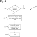
- the invention relates to methods for relocating a vehicle, and an exemplary method is shown in fig. 4 .
- step 401 it is determined whether the vehicle is to be relocated pending a further test of the vehicle to be performed.
- step 402 the adapter plate is disconnected from the dynamometer test unit while still remaining secured to the wheel shaft (half shaft).
- all tested shafts can be arranged to be disconnected in the same manner leaving the adapter plates secured to the vehicle. Since the adapter plates preferably do not touch ground during testing, e.g. jacks can be used to support the vehicle while the adapter plates are disconnected form the dynamometer test unit.
- the vehicle When all adapter plats have been disconnected, and possibly wiring used in the testing, the vehicle is free to be relocated, supported by adapter plates only or a combination of adapter plates and wheels, although at least one wheel hub is supported by an adapter plate and no wheel.
- the vehicle can be relocated to the dynamometer test system supported by the one or more adapter plates. Consequently, according to the invention, it is provided adapter plates that allow for relocation of the vehicle in a manner that significantly may reduce the time it takes to set up a test since the adapter plates are already attached to the vehicle and ready to be fixedly connected to the dynamometer test units.
- each dynamometer test unit comprises a single power source consisting of an electrical machine.
- the dynamometer test unit comprises two or more individually controllable power sources, which can be electrical machines, hydraulic pumps or any suitable combination thereof. If two or more power sources are used for a single dynamometer test unit, the moment of inertia can be separately determined for the power sources so that only moment of inertia (power sources) currently participating in the measurements are used when compensating the results.
- the present invention has been exemplified in connection with testing of a particular kind of vehicles.
- the present invention is applicable for testing of any kind of vehicle, such as hybrid vehicles or conventional two or four wheel drive combustion engine vehicles, or any other kind of hybrid vehicle other than what has been disclosed above.
- more than two dynamometer test units can be used for being connected to more than two wheels, and it is also contemplated that only one wheel shaft is connected to a dynamometer test unit, e.g. if an electric motor of the vehicle acts only on one wheel shaft.
Landscapes
- Physics & Mathematics (AREA)
- General Physics & Mathematics (AREA)
- Chemical & Material Sciences (AREA)
- Engineering & Computer Science (AREA)
- Combustion & Propulsion (AREA)
- Testing Of Engines (AREA)
- Testing Of Devices, Machine Parts, Or Other Structures Thereof (AREA)
Claims (9)
- Verfahren zur dynamometrischen Prüfung eines Fahrzeugs (100) in einem Fahrzeugdynamometersystem, umfassend mindestens eine Dynamometerprüfeinheit (110, 111) mit einer Stromquelle (201), wobei die Stromquelle (201) eine Ausgangswelle (202) umfasst, die zur Drehung mit einer Fahrzeugradwelle (105, 106) angeordnet ist, wobei das System ferner eine Adapterplatte (204) umfasst, wobei die Adapterplatte (204) eine Einrichtung zum Zulassen einer festen Verbindung der Adapterplatte (204) mit einer Radnabe (203) der Fahrzeugradwelle (105, 106) umfasst und die Adapterplatte (204) ferner eine Einrichtung zum Zulassen einer festen Verbindung zur Ausgangswelle (202) der Prüfeinheit (110, 111) umfasst, um dadurch die Ausgangswelle (202) der Dynamometerprüfeinheit (110, 111) starr mit der Radwelle (105, 106) zu koppeln, die folgenden Schritte umfassend:- Verlagern des Fahrzeugs (100) unter Verwendung der Adapterplatte (204), wobei die Adapterplatte (204) derart ausgestaltet ist, dass, wenn sie starr mit der Radnabe (203) gekoppelt, jedoch von der Dynamometerprüfeinheit (110, 111) getrennt ist, die Adapterplatte (204) das Fahrzeug (100) abstützt, wobei die Adapterplatte (204) mit der Radwelle (205, 206) drehfest gekoppelt ist, sodass sich die Adapterplatte (204) während der Prüfung mit der Radwelle (205, 206) dreht, und wobei die Adapterplatte (204) einen Außenumfang zum Berühren der Fläche, auf der ein Fahrzeug (100) beim Abstützen des Fahrzeugs (100) vorhanden ist, umfasst,dadurch gekennzeichnet, dass: während der Prüfung das Gewicht des Fahrzeugs von der Dynamometerprüfeinheit (110, 111) abgestützt wird und die Höhe der Ausgangswelle (202) derart gesteuert wird, dass sich die Adapterplatte frei dreht, ohne den Boden zu berühren.
- Verfahren nach Anspruch 1, ferner Folgendes umfassend:- Abstützen von mindestens zwei Radwellen (105, 106) durch je eine Adapterplatte (204) beim Verlagern des Fahrzeugs (100).
- Verfahren nach Anspruch 1 oder 2, wobei die Adapterplatte (204) einen Durchmesser aufweist, der im Wesentlichen dem Raddurchmesser des geprüften Fahrzeugs (100) entspricht.
- Verfahren nach einem der Ansprüche 1-3, ferner umfassend:- Auswählen einer Adapterplatte (204), die zusätzlich eine Adapterplatte (204) ist, die ein Gewicht aufweist, das auf Grundlage eines gewünschten Trägheitsmoments der Dynamometerprüfeinheit (110, 111) und/oder Radwelle (105, 106) beim Prüfen ausgewählt wird.
- Verfahren nach einem der Ansprüche 1-4, wobei die Adapterplatte (204) dazu ausgestaltet ist, einen derartigen Durchmesser aufzuweisen, dass ein Bauchspielraum des Fahrzeugs (100) beim Abstützen des Fahrzeugs (100) erreicht wird.
- Verfahren nach einem der Ansprüche 1-5, wobei eine Schicht aus Kautschuk oder einer Kautschukzusammensetzung an einem Außenrand der Adapterplatte (204) vorgesehen ist, um die Fläche zu berühren, auf der ein Fahrzeug (100) beim Abstützen des Fahrzeugs (100) vorhanden ist.
- Verfahren nach einem der Ansprüche 1-6, wobei die Adapterplatte (204) einen Durchmesser von mindestens 450 mm aufweist.
- Verfahren nach einem der Ansprüche 1-7, wobei die Adapterplatte (204) einen Durchmesser in einem der folgenden Intervalle aufweist: 250 mm bis 800 mm; 500 mm bis 750 mm.
- Verfahren nach einem der Ansprüche 1-8, wobei die Adapterplatte (204) eine Speichengestaltung aufweist.
Applications Claiming Priority (2)
| Application Number | Priority Date | Filing Date | Title |
|---|---|---|---|
| SE1650758A SE539808C2 (en) | 2016-05-31 | 2016-05-31 | Method and system for use in dynamometer testing of a motor vehicle |
| PCT/SE2017/050573 WO2017209681A1 (en) | 2016-05-31 | 2017-05-30 | Method and system for use in dynamometer testing of a motor vehicle |
Publications (3)
| Publication Number | Publication Date |
|---|---|
| EP3465131A1 EP3465131A1 (de) | 2019-04-10 |
| EP3465131A4 EP3465131A4 (de) | 2020-01-22 |
| EP3465131B1 true EP3465131B1 (de) | 2024-08-14 |
Family
ID=60477385
Family Applications (1)
| Application Number | Title | Priority Date | Filing Date |
|---|---|---|---|
| EP17807113.0A Active EP3465131B1 (de) | 2016-05-31 | 2017-05-30 | Verfahren zur dynamometrischen prüfung eines kraftfahrzeuges |
Country Status (6)
| Country | Link |
|---|---|
| US (1) | US10739234B2 (de) |
| EP (1) | EP3465131B1 (de) |
| JP (1) | JP6941628B2 (de) |
| CN (1) | CN109219739B (de) |
| SE (1) | SE539808C2 (de) |
| WO (1) | WO2017209681A1 (de) |
Families Citing this family (9)
| Publication number | Priority date | Publication date | Assignee | Title |
|---|---|---|---|---|
| SE540688C2 (en) * | 2017-05-16 | 2018-10-09 | Rototest Int Ab | Method and system for use in dynamometer testing of a motor vehicle |
| WO2019053940A1 (ja) * | 2017-09-15 | 2019-03-21 | 東洋電機製造株式会社 | シャシダイナモ装置用負荷モータ |
| CN111929078A (zh) * | 2020-08-31 | 2020-11-13 | 中汽研汽车检验中心(天津)有限公司 | 一种基于SiC模块用电动汽车能耗测量装置 |
| DE102021205144B3 (de) | 2021-05-20 | 2022-09-01 | Zf Friedrichshafen Ag | Prüfrad für einen Antriebsstrangprüfstand und Antriebsstrangprüfstand |
| DE102021205741B3 (de) | 2021-06-08 | 2022-09-15 | Zf Friedrichshafen Ag | Abstellmodul für einen Antriebsstrangprüfstand |
| CN113466703B (zh) * | 2021-06-30 | 2023-02-17 | 中国汽车技术研究中心有限公司 | 燃料电池汽车冷启动测试方法、电子设备及介质 |
| JP7338757B1 (ja) * | 2022-08-04 | 2023-09-05 | 株式会社明電舎 | 車両試験装置用のハブ連結装置 |
| CN115308100A (zh) * | 2022-08-17 | 2022-11-08 | 北京理工大学 | 一种机动车刹车颗粒物测量系统和方法 |
| SE2450792A1 (en) * | 2024-07-10 | 2026-01-11 | Rototest Int Ab | Method and apparatus for dynamometer testing of a motor vehicle |
Family Cites Families (21)
| Publication number | Priority date | Publication date | Assignee | Title |
|---|---|---|---|---|
| US4092855A (en) * | 1977-01-28 | 1978-06-06 | Caterpillar Tractor Co. | Dynamometer and coupling for a test stand |
| US4062234A (en) * | 1977-01-28 | 1977-12-13 | Caterpillar Tractor Co. | Dynamometer test stand |
| US4277972A (en) * | 1979-12-06 | 1981-07-14 | Modular Data Systems, Inc. | Engine dynamometer |
| US4669318A (en) | 1984-03-29 | 1987-06-02 | Nils G. Engstrom | Apparatus for dynamometer testing of motor vehicles |
| DE4136508A1 (de) * | 1991-11-06 | 1993-05-13 | Renk Ag | Kraftfahrzeugpruefstand |
| US5323644A (en) * | 1992-07-06 | 1994-06-28 | Ford Motor Company | Traction control road simulator |
| CN2306504Y (zh) * | 1997-07-24 | 1999-02-03 | 湖南省长沙汽车检测站 | 前轮驱动机动车测速、测功定位机 |
| JP4082101B2 (ja) * | 2002-06-18 | 2008-04-30 | トヨタ自動車株式会社 | シャシダイナモ装置および車両試験方法 |
| JP4232612B2 (ja) * | 2003-11-20 | 2009-03-04 | 株式会社明電舎 | シャシーダイナモメータ |
| EP2018534B1 (de) * | 2006-05-16 | 2017-10-25 | Rototest International AB | Vefahren und vorrichtung zur dynamometrischen prüfung eines kraftfahrzeuges und von fahrzeugkomponenten |
| KR100803847B1 (ko) * | 2006-05-26 | 2008-02-14 | 현대자동차주식회사 | 엔진의 성능시험용 회전장치 |
| CN201212854Y (zh) * | 2008-01-11 | 2009-03-25 | 北京欧润特科技有限公司 | 转毂底盘测功机 |
| JP5137789B2 (ja) * | 2008-11-18 | 2013-02-06 | 独立行政法人交通安全環境研究所 | 模擬車輪および車両試験装置 |
| DE202010018277U1 (de) * | 2010-04-22 | 2015-05-15 | Ipetronik Gmbh & Co. Kg | Radsatz |
| DE202010006682U1 (de) * | 2010-05-11 | 2010-08-05 | Horiba Europe Gmbh | Prüfstand für Lastkraftwagen und Adaptervorrichtung dafür |
| EP2580566B1 (de) * | 2010-06-14 | 2019-11-13 | Rototest International AB | Verfahren und vorrichtung zur dynamometrischen prüfung eines kraftfahrzeugs |
| AT512006A1 (de) | 2011-10-11 | 2013-04-15 | Seibt Kristl & Co Gmbh | Vorrichtung für ein prüfrad zum prüfen des antriebsstrangs eines fahrzeugs und prüfrad |
| ES2732202T3 (es) * | 2013-12-09 | 2019-11-21 | Rototest Int Ab | Método y sistema para su uso en una prueba dinamométrica de un vehículo motorizado |
| SE538492C2 (sv) * | 2014-03-31 | 2016-08-02 | Rototest Int Ab | Förfarande och system för användning vid dynamometerprovningav ett motorfordon |
| US9752961B2 (en) * | 2014-06-19 | 2017-09-05 | Avl Test Systems, Inc. | Dual-purpose dynamometer |
| CN204330349U (zh) * | 2014-12-20 | 2015-05-13 | 重庆凯特动力科技有限公司 | 一种测功机安全保护装置 |
-
2016
- 2016-05-31 SE SE1650758A patent/SE539808C2/en unknown
-
2017
- 2017-05-30 JP JP2018560158A patent/JP6941628B2/ja active Active
- 2017-05-30 WO PCT/SE2017/050573 patent/WO2017209681A1/en not_active Ceased
- 2017-05-30 EP EP17807113.0A patent/EP3465131B1/de active Active
- 2017-05-30 US US16/305,749 patent/US10739234B2/en active Active
- 2017-05-30 CN CN201780033696.XA patent/CN109219739B/zh active Active
Also Published As
| Publication number | Publication date |
|---|---|
| CN109219739B (zh) | 2021-03-02 |
| SE1650758A1 (en) | 2017-12-01 |
| US20190368972A1 (en) | 2019-12-05 |
| SE539808C2 (en) | 2017-12-05 |
| CN109219739A (zh) | 2019-01-15 |
| JP6941628B2 (ja) | 2021-09-29 |
| US10739234B2 (en) | 2020-08-11 |
| WO2017209681A1 (en) | 2017-12-07 |
| EP3465131A1 (de) | 2019-04-10 |
| JP2019518211A (ja) | 2019-06-27 |
| EP3465131A4 (de) | 2020-01-22 |
Similar Documents
| Publication | Publication Date | Title |
|---|---|---|
| US10739234B2 (en) | Method and system for use in dynamometer testing of a motor vehicle | |
| US9109973B2 (en) | Test wheel arrangement with rotary mounting blocking device | |
| EP3635360B1 (de) | Verfahren und system zur verwendung in der dynamometerprüfung eines kraftfahrzeugs | |
| EP2652476B1 (de) | Verfahren und vorrichtung zur dynamometrischen prüfung eines kraftfahrzeugs | |
| US11506551B2 (en) | Method and apparatus for dynamometer testing of a motor vehicle | |
| JP7229137B2 (ja) | 自動車試験システム | |
| US11529862B2 (en) | Systems and methods for improving propulsion of a vehicle using selectively attachable hub motors and rotatable axles | |
| US4862736A (en) | Method and apparatus for the transfer of forces and/or moments in vehicle testing | |
| US11761501B2 (en) | Friction simulating device | |
| US20250251311A1 (en) | Apparatus and method for testing automated vehicles | |
| US4324133A (en) | Torque measuring device | |
| RU126294U1 (ru) | Мобильный стенд для экспресс-диагностики тормозных механизмов легковых транспортных средств | |
| RU2335753C1 (ru) | Стенд для силовых испытаний колесного транспортного средства | |
| CN218481236U (zh) | 一种差速器综合试验台 | |
| JPH0348514Y2 (de) | ||
| RU2456184C1 (ru) | Передвижной прицеп-стенд для диагностики, регулировки, ремонта, установки тормозной системы колес автомобилей | |
| CN115885162A (zh) | 用于驱动系测试台的耦联模块、输出模块和驱动系测试台 | |
| CN207423540U (zh) | 一种新能源汽车检测器具 | |
| US20250198881A1 (en) | Steerable synchronized wheelspeed dynomometer system | |
| WO2019151934A1 (en) | Method and apparatus for dynamometer testing of a motor vehicle | |
| CN212321066U (zh) | 一种电子限滑差速器试验台架 | |
| CN214607462U (zh) | 鼓式制动器连接结构、车辆制动系统及车辆 | |
| JPH1019739A (ja) | シャシダイナモメータとそのドラム移動機構 | |
| US20190195288A1 (en) | Housing Drive Connection For A Constant Velocity Joint | |
| WO2026015058A1 (en) | Method and apparatus for dynamometer testing of a motor vehicle |
Legal Events
| Date | Code | Title | Description |
|---|---|---|---|
| STAA | Information on the status of an ep patent application or granted ep patent |
Free format text: STATUS: THE INTERNATIONAL PUBLICATION HAS BEEN MADE |
|
| PUAI | Public reference made under article 153(3) epc to a published international application that has entered the european phase |
Free format text: ORIGINAL CODE: 0009012 |
|
| STAA | Information on the status of an ep patent application or granted ep patent |
Free format text: STATUS: REQUEST FOR EXAMINATION WAS MADE |
|
| 17P | Request for examination filed |
Effective date: 20181126 |
|
| AK | Designated contracting states |
Kind code of ref document: A1 Designated state(s): AL AT BE BG CH CY CZ DE DK EE ES FI FR GB GR HR HU IE IS IT LI LT LU LV MC MK MT NL NO PL PT RO RS SE SI SK SM TR |
|
| AX | Request for extension of the european patent |
Extension state: BA ME |
|
| DAV | Request for validation of the european patent (deleted) | ||
| DAX | Request for extension of the european patent (deleted) | ||
| A4 | Supplementary search report drawn up and despatched |
Effective date: 20191219 |
|
| RIC1 | Information provided on ipc code assigned before grant |
Ipc: G01M 15/04 20060101ALI20191213BHEP Ipc: G01M 17/007 20060101AFI20191213BHEP |
|
| STAA | Information on the status of an ep patent application or granted ep patent |
Free format text: STATUS: EXAMINATION IS IN PROGRESS |
|
| 17Q | First examination report despatched |
Effective date: 20220221 |
|
| GRAP | Despatch of communication of intention to grant a patent |
Free format text: ORIGINAL CODE: EPIDOSNIGR1 |
|
| STAA | Information on the status of an ep patent application or granted ep patent |
Free format text: STATUS: GRANT OF PATENT IS INTENDED |
|
| INTG | Intention to grant announced |
Effective date: 20240410 |
|
| GRAS | Grant fee paid |
Free format text: ORIGINAL CODE: EPIDOSNIGR3 |
|
| GRAA | (expected) grant |
Free format text: ORIGINAL CODE: 0009210 |
|
| STAA | Information on the status of an ep patent application or granted ep patent |
Free format text: STATUS: THE PATENT HAS BEEN GRANTED |
|
| AK | Designated contracting states |
Kind code of ref document: B1 Designated state(s): AL AT BE BG CH CY CZ DE DK EE ES FI FR GB GR HR HU IE IS IT LI LT LU LV MC MK MT NL NO PL PT RO RS SE SI SK SM TR |
|
| REG | Reference to a national code |
Ref country code: GB Ref legal event code: FG4D |
|
| REG | Reference to a national code |
Ref country code: CH Ref legal event code: EP |
|
| REG | Reference to a national code |
Ref country code: DE Ref legal event code: R096 Ref document number: 602017084101 Country of ref document: DE |
|
| REG | Reference to a national code |
Ref country code: IE Ref legal event code: FG4D |
|
| REG | Reference to a national code |
Ref country code: LT Ref legal event code: MG9D |
|
| REG | Reference to a national code |
Ref country code: NL Ref legal event code: MP Effective date: 20240814 |
|
| P01 | Opt-out of the competence of the unified patent court (upc) registered |
Free format text: CASE NUMBER: APP_62890/2024 Effective date: 20241126 |
|
| PG25 | Lapsed in a contracting state [announced via postgrant information from national office to epo] |
Ref country code: NO Free format text: LAPSE BECAUSE OF FAILURE TO SUBMIT A TRANSLATION OF THE DESCRIPTION OR TO PAY THE FEE WITHIN THE PRESCRIBED TIME-LIMIT Effective date: 20241114 |
|
| REG | Reference to a national code |
Ref country code: AT Ref legal event code: MK05 Ref document number: 1713691 Country of ref document: AT Kind code of ref document: T Effective date: 20240814 |
|
| PG25 | Lapsed in a contracting state [announced via postgrant information from national office to epo] |
Ref country code: PL Free format text: LAPSE BECAUSE OF FAILURE TO SUBMIT A TRANSLATION OF THE DESCRIPTION OR TO PAY THE FEE WITHIN THE PRESCRIBED TIME-LIMIT Effective date: 20240814 Ref country code: PT Free format text: LAPSE BECAUSE OF FAILURE TO SUBMIT A TRANSLATION OF THE DESCRIPTION OR TO PAY THE FEE WITHIN THE PRESCRIBED TIME-LIMIT Effective date: 20241216 Ref country code: FI Free format text: LAPSE BECAUSE OF FAILURE TO SUBMIT A TRANSLATION OF THE DESCRIPTION OR TO PAY THE FEE WITHIN THE PRESCRIBED TIME-LIMIT Effective date: 20240814 Ref country code: GR Free format text: LAPSE BECAUSE OF FAILURE TO SUBMIT A TRANSLATION OF THE DESCRIPTION OR TO PAY THE FEE WITHIN THE PRESCRIBED TIME-LIMIT Effective date: 20241115 Ref country code: NL Free format text: LAPSE BECAUSE OF FAILURE TO SUBMIT A TRANSLATION OF THE DESCRIPTION OR TO PAY THE FEE WITHIN THE PRESCRIBED TIME-LIMIT Effective date: 20240814 |
|
| PG25 | Lapsed in a contracting state [announced via postgrant information from national office to epo] |
Ref country code: BG Free format text: LAPSE BECAUSE OF FAILURE TO SUBMIT A TRANSLATION OF THE DESCRIPTION OR TO PAY THE FEE WITHIN THE PRESCRIBED TIME-LIMIT Effective date: 20240814 |
|
| PG25 | Lapsed in a contracting state [announced via postgrant information from national office to epo] |
Ref country code: LV Free format text: LAPSE BECAUSE OF FAILURE TO SUBMIT A TRANSLATION OF THE DESCRIPTION OR TO PAY THE FEE WITHIN THE PRESCRIBED TIME-LIMIT Effective date: 20240814 |
|
| PG25 | Lapsed in a contracting state [announced via postgrant information from national office to epo] |
Ref country code: AT Free format text: LAPSE BECAUSE OF FAILURE TO SUBMIT A TRANSLATION OF THE DESCRIPTION OR TO PAY THE FEE WITHIN THE PRESCRIBED TIME-LIMIT Effective date: 20240814 Ref country code: IS Free format text: LAPSE BECAUSE OF FAILURE TO SUBMIT A TRANSLATION OF THE DESCRIPTION OR TO PAY THE FEE WITHIN THE PRESCRIBED TIME-LIMIT Effective date: 20241214 |
|
| PG25 | Lapsed in a contracting state [announced via postgrant information from national office to epo] |
Ref country code: HR Free format text: LAPSE BECAUSE OF FAILURE TO SUBMIT A TRANSLATION OF THE DESCRIPTION OR TO PAY THE FEE WITHIN THE PRESCRIBED TIME-LIMIT Effective date: 20240814 |
|
| PG25 | Lapsed in a contracting state [announced via postgrant information from national office to epo] |
Ref country code: RS Free format text: LAPSE BECAUSE OF FAILURE TO SUBMIT A TRANSLATION OF THE DESCRIPTION OR TO PAY THE FEE WITHIN THE PRESCRIBED TIME-LIMIT Effective date: 20241114 Ref country code: ES Free format text: LAPSE BECAUSE OF FAILURE TO SUBMIT A TRANSLATION OF THE DESCRIPTION OR TO PAY THE FEE WITHIN THE PRESCRIBED TIME-LIMIT Effective date: 20240814 |
|
| PG25 | Lapsed in a contracting state [announced via postgrant information from national office to epo] |
Ref country code: RS Free format text: LAPSE BECAUSE OF FAILURE TO SUBMIT A TRANSLATION OF THE DESCRIPTION OR TO PAY THE FEE WITHIN THE PRESCRIBED TIME-LIMIT Effective date: 20241114 Ref country code: PT Free format text: LAPSE BECAUSE OF FAILURE TO SUBMIT A TRANSLATION OF THE DESCRIPTION OR TO PAY THE FEE WITHIN THE PRESCRIBED TIME-LIMIT Effective date: 20241216 Ref country code: PL Free format text: LAPSE BECAUSE OF FAILURE TO SUBMIT A TRANSLATION OF THE DESCRIPTION OR TO PAY THE FEE WITHIN THE PRESCRIBED TIME-LIMIT Effective date: 20240814 Ref country code: NO Free format text: LAPSE BECAUSE OF FAILURE TO SUBMIT A TRANSLATION OF THE DESCRIPTION OR TO PAY THE FEE WITHIN THE PRESCRIBED TIME-LIMIT Effective date: 20241114 Ref country code: NL Free format text: LAPSE BECAUSE OF FAILURE TO SUBMIT A TRANSLATION OF THE DESCRIPTION OR TO PAY THE FEE WITHIN THE PRESCRIBED TIME-LIMIT Effective date: 20240814 Ref country code: LV Free format text: LAPSE BECAUSE OF FAILURE TO SUBMIT A TRANSLATION OF THE DESCRIPTION OR TO PAY THE FEE WITHIN THE PRESCRIBED TIME-LIMIT Effective date: 20240814 Ref country code: IS Free format text: LAPSE BECAUSE OF FAILURE TO SUBMIT A TRANSLATION OF THE DESCRIPTION OR TO PAY THE FEE WITHIN THE PRESCRIBED TIME-LIMIT Effective date: 20241214 Ref country code: HR Free format text: LAPSE BECAUSE OF FAILURE TO SUBMIT A TRANSLATION OF THE DESCRIPTION OR TO PAY THE FEE WITHIN THE PRESCRIBED TIME-LIMIT Effective date: 20240814 Ref country code: GR Free format text: LAPSE BECAUSE OF FAILURE TO SUBMIT A TRANSLATION OF THE DESCRIPTION OR TO PAY THE FEE WITHIN THE PRESCRIBED TIME-LIMIT Effective date: 20241115 Ref country code: FI Free format text: LAPSE BECAUSE OF FAILURE TO SUBMIT A TRANSLATION OF THE DESCRIPTION OR TO PAY THE FEE WITHIN THE PRESCRIBED TIME-LIMIT Effective date: 20240814 Ref country code: ES Free format text: LAPSE BECAUSE OF FAILURE TO SUBMIT A TRANSLATION OF THE DESCRIPTION OR TO PAY THE FEE WITHIN THE PRESCRIBED TIME-LIMIT Effective date: 20240814 Ref country code: BG Free format text: LAPSE BECAUSE OF FAILURE TO SUBMIT A TRANSLATION OF THE DESCRIPTION OR TO PAY THE FEE WITHIN THE PRESCRIBED TIME-LIMIT Effective date: 20240814 Ref country code: AT Free format text: LAPSE BECAUSE OF FAILURE TO SUBMIT A TRANSLATION OF THE DESCRIPTION OR TO PAY THE FEE WITHIN THE PRESCRIBED TIME-LIMIT Effective date: 20240814 |
|
| PG25 | Lapsed in a contracting state [announced via postgrant information from national office to epo] |
Ref country code: RO Free format text: LAPSE BECAUSE OF FAILURE TO SUBMIT A TRANSLATION OF THE DESCRIPTION OR TO PAY THE FEE WITHIN THE PRESCRIBED TIME-LIMIT Effective date: 20240814 Ref country code: SM Free format text: LAPSE BECAUSE OF FAILURE TO SUBMIT A TRANSLATION OF THE DESCRIPTION OR TO PAY THE FEE WITHIN THE PRESCRIBED TIME-LIMIT Effective date: 20240814 Ref country code: DK Free format text: LAPSE BECAUSE OF FAILURE TO SUBMIT A TRANSLATION OF THE DESCRIPTION OR TO PAY THE FEE WITHIN THE PRESCRIBED TIME-LIMIT Effective date: 20240814 |
|
| PG25 | Lapsed in a contracting state [announced via postgrant information from national office to epo] |
Ref country code: EE Free format text: LAPSE BECAUSE OF FAILURE TO SUBMIT A TRANSLATION OF THE DESCRIPTION OR TO PAY THE FEE WITHIN THE PRESCRIBED TIME-LIMIT Effective date: 20240814 |
|
| PG25 | Lapsed in a contracting state [announced via postgrant information from national office to epo] |
Ref country code: CZ Free format text: LAPSE BECAUSE OF FAILURE TO SUBMIT A TRANSLATION OF THE DESCRIPTION OR TO PAY THE FEE WITHIN THE PRESCRIBED TIME-LIMIT Effective date: 20240814 |
|
| PG25 | Lapsed in a contracting state [announced via postgrant information from national office to epo] |
Ref country code: IT Free format text: LAPSE BECAUSE OF FAILURE TO SUBMIT A TRANSLATION OF THE DESCRIPTION OR TO PAY THE FEE WITHIN THE PRESCRIBED TIME-LIMIT Effective date: 20240814 Ref country code: SK Free format text: LAPSE BECAUSE OF FAILURE TO SUBMIT A TRANSLATION OF THE DESCRIPTION OR TO PAY THE FEE WITHIN THE PRESCRIBED TIME-LIMIT Effective date: 20240814 |
|
| REG | Reference to a national code |
Ref country code: DE Ref legal event code: R097 Ref document number: 602017084101 Country of ref document: DE |
|
| PLBE | No opposition filed within time limit |
Free format text: ORIGINAL CODE: 0009261 |
|
| STAA | Information on the status of an ep patent application or granted ep patent |
Free format text: STATUS: NO OPPOSITION FILED WITHIN TIME LIMIT |
|
| 26N | No opposition filed |
Effective date: 20250515 |
|
| PG25 | Lapsed in a contracting state [announced via postgrant information from national office to epo] |
Ref country code: SE Free format text: LAPSE BECAUSE OF FAILURE TO SUBMIT A TRANSLATION OF THE DESCRIPTION OR TO PAY THE FEE WITHIN THE PRESCRIBED TIME-LIMIT Effective date: 20240814 |
|
| REG | Reference to a national code |
Ref country code: CH Ref legal event code: H13 Free format text: ST27 STATUS EVENT CODE: U-0-0-H10-H13 (AS PROVIDED BY THE NATIONAL OFFICE) Effective date: 20251223 |
|
| PG25 | Lapsed in a contracting state [announced via postgrant information from national office to epo] |
Ref country code: LU Free format text: LAPSE BECAUSE OF NON-PAYMENT OF DUE FEES Effective date: 20250530 |
|
| PG25 | Lapsed in a contracting state [announced via postgrant information from national office to epo] |
Ref country code: CH Free format text: LAPSE BECAUSE OF NON-PAYMENT OF DUE FEES Effective date: 20250531 |
|
| REG | Reference to a national code |
Ref country code: BE Ref legal event code: MM Effective date: 20250531 |
|
| PG25 | Lapsed in a contracting state [announced via postgrant information from national office to epo] |
Ref country code: MC Free format text: LAPSE BECAUSE OF FAILURE TO SUBMIT A TRANSLATION OF THE DESCRIPTION OR TO PAY THE FEE WITHIN THE PRESCRIBED TIME-LIMIT Effective date: 20240814 |
|
| PGFP | Annual fee paid to national office [announced via postgrant information from national office to epo] |
Ref country code: GB Payment date: 20260331 Year of fee payment: 10 |
|
| PG25 | Lapsed in a contracting state [announced via postgrant information from national office to epo] |
Ref country code: IE Free format text: LAPSE BECAUSE OF NON-PAYMENT OF DUE FEES Effective date: 20250530 |
|
| PG25 | Lapsed in a contracting state [announced via postgrant information from national office to epo] |
Ref country code: BE Free format text: LAPSE BECAUSE OF NON-PAYMENT OF DUE FEES Effective date: 20250531 |
|
| PG25 | Lapsed in a contracting state [announced via postgrant information from national office to epo] |
Ref country code: LT Free format text: LAPSE BECAUSE OF FAILURE TO SUBMIT A TRANSLATION OF THE DESCRIPTION OR TO PAY THE FEE WITHIN THE PRESCRIBED TIME-LIMIT Effective date: 20240814 |
|
| PGFP | Annual fee paid to national office [announced via postgrant information from national office to epo] |
Ref country code: DE Payment date: 20260519 Year of fee payment: 10 |
|
| PGFP | Annual fee paid to national office [announced via postgrant information from national office to epo] |
Ref country code: FR Payment date: 20260519 Year of fee payment: 10 |
|
| PG25 | Lapsed in a contracting state [announced via postgrant information from national office to epo] |
Ref country code: CY Free format text: LAPSE BECAUSE OF FAILURE TO SUBMIT A TRANSLATION OF THE DESCRIPTION OR TO PAY THE FEE WITHIN THE PRESCRIBED TIME-LIMIT Effective date: 20240814 |