EP3465754B1 - Ensemble de diodes électroluminescentes compact - Google Patents
Ensemble de diodes électroluminescentes compact Download PDFInfo
- Publication number
- EP3465754B1 EP3465754B1 EP17808003.2A EP17808003A EP3465754B1 EP 3465754 B1 EP3465754 B1 EP 3465754B1 EP 17808003 A EP17808003 A EP 17808003A EP 3465754 B1 EP3465754 B1 EP 3465754B1
- Authority
- EP
- European Patent Office
- Prior art keywords
- light
- emitting diode
- emitting diodes
- housing
- vehicle
- Prior art date
- Legal status (The legal status is an assumption and is not a legal conclusion. Google has not performed a legal analysis and makes no representation as to the accuracy of the status listed.)
- Active
Links
Images



Classifications
-
- B—PERFORMING OPERATIONS; TRANSPORTING
- B60—VEHICLES IN GENERAL
- B60Q—ARRANGEMENT OF SIGNALLING OR LIGHTING DEVICES, THE MOUNTING OR SUPPORTING THEREOF OR CIRCUITS THEREFOR, FOR VEHICLES IN GENERAL
- B60Q9/00—Arrangement or adaptation of signal devices not provided for in one of main groups B60Q1/00 - B60Q7/00, e.g. haptic signalling
-
- H—ELECTRICITY
- H10—SEMICONDUCTOR DEVICES; ELECTRIC SOLID-STATE DEVICES NOT OTHERWISE PROVIDED FOR
- H10W—GENERIC PACKAGES, INTERCONNECTIONS, CONNECTORS OR OTHER CONSTRUCTIONAL DETAILS OF DEVICES COVERED BY CLASS H10
- H10W90/00—Package configurations
-
- B—PERFORMING OPERATIONS; TRANSPORTING
- B60—VEHICLES IN GENERAL
- B60R—VEHICLES, VEHICLE FITTINGS, OR VEHICLE PARTS, NOT OTHERWISE PROVIDED FOR
- B60R1/00—Optical viewing arrangements; Real-time viewing arrangements for drivers or passengers using optical image capturing systems, e.g. cameras or video systems specially adapted for use in or on vehicles
- B60R1/12—Mirror assemblies combined with other articles, e.g. clocks
- B60R1/1207—Mirror assemblies combined with other articles, e.g. clocks with lamps; with turn indicators
-
- F—MECHANICAL ENGINEERING; LIGHTING; HEATING; WEAPONS; BLASTING
- F21—LIGHTING
- F21S—NON-PORTABLE LIGHTING DEVICES; SYSTEMS THEREOF; VEHICLE LIGHTING DEVICES SPECIALLY ADAPTED FOR VEHICLE EXTERIORS
- F21S43/00—Signalling devices specially adapted for vehicle exteriors, e.g. brake lamps, direction indicator lights or reversing lights
- F21S43/10—Signalling devices specially adapted for vehicle exteriors, e.g. brake lamps, direction indicator lights or reversing lights characterised by the light source
- F21S43/13—Signalling devices specially adapted for vehicle exteriors, e.g. brake lamps, direction indicator lights or reversing lights characterised by the light source characterised by the type of light source
- F21S43/14—Light emitting diodes [LED]
-
- G—PHYSICS
- G09—EDUCATION; CRYPTOGRAPHY; DISPLAY; ADVERTISING; SEALS
- G09G—ARRANGEMENTS OR CIRCUITS FOR CONTROL OF INDICATING DEVICES USING STATIC MEANS TO PRESENT VARIABLE INFORMATION
- G09G3/00—Control arrangements or circuits, of interest only in connection with visual indicators other than cathode-ray tubes
- G09G3/20—Control arrangements or circuits, of interest only in connection with visual indicators other than cathode-ray tubes for presentation of an assembly of a number of characters, e.g. a page, by composing the assembly by combination of individual elements arranged in a matrix no fixed position being assigned to or needed to be assigned to the individual characters or partial characters
- G09G3/22—Control arrangements or circuits, of interest only in connection with visual indicators other than cathode-ray tubes for presentation of an assembly of a number of characters, e.g. a page, by composing the assembly by combination of individual elements arranged in a matrix no fixed position being assigned to or needed to be assigned to the individual characters or partial characters using controlled light sources
- G09G3/30—Control arrangements or circuits, of interest only in connection with visual indicators other than cathode-ray tubes for presentation of an assembly of a number of characters, e.g. a page, by composing the assembly by combination of individual elements arranged in a matrix no fixed position being assigned to or needed to be assigned to the individual characters or partial characters using controlled light sources using electroluminescent panels
- G09G3/32—Control arrangements or circuits, of interest only in connection with visual indicators other than cathode-ray tubes for presentation of an assembly of a number of characters, e.g. a page, by composing the assembly by combination of individual elements arranged in a matrix no fixed position being assigned to or needed to be assigned to the individual characters or partial characters using controlled light sources using electroluminescent panels semiconductive, e.g. using light-emitting diodes [LED]
-
- H—ELECTRICITY
- H05—ELECTRIC TECHNIQUES NOT OTHERWISE PROVIDED FOR
- H05B—ELECTRIC HEATING; ELECTRIC LIGHT SOURCES NOT OTHERWISE PROVIDED FOR; CIRCUIT ARRANGEMENTS FOR ELECTRIC LIGHT SOURCES, IN GENERAL
- H05B45/00—Circuit arrangements for operating light-emitting diodes [LED]
- H05B45/10—Controlling the intensity of the light
-
- F—MECHANICAL ENGINEERING; LIGHTING; HEATING; WEAPONS; BLASTING
- F21—LIGHTING
- F21W—INDEXING SCHEME ASSOCIATED WITH SUBCLASSES F21K, F21L, F21S and F21V, RELATING TO USES OR APPLICATIONS OF LIGHTING DEVICES OR SYSTEMS
- F21W2103/00—Exterior vehicle lighting devices for signalling purposes
- F21W2103/30—Hazard lights
-
- F—MECHANICAL ENGINEERING; LIGHTING; HEATING; WEAPONS; BLASTING
- F21—LIGHTING
- F21Y—INDEXING SCHEME ASSOCIATED WITH SUBCLASSES F21K, F21L, F21S and F21V, RELATING TO THE FORM OR THE KIND OF THE LIGHT SOURCES OR OF THE COLOUR OF THE LIGHT EMITTED
- F21Y2115/00—Light-generating elements of semiconductor light sources
- F21Y2115/10—Light-emitting diodes [LED]
Definitions
- the present invention is directed to a compact light-emitting diode arrangement which can be used generically, but which is particularly advantageous for use in a vehicle due to its compact design.
- the compact light-emitting diode arrangement can be used as interior lighting in an automobile.
- the present invention is further directed to a vehicle component having the compact light-emitting diode arrangement.
- a method for producing the compact light-emitting diode arrangement is proposed, as well as a computer program product with control commands which implement the proposed method.
- WO 2008/025625 shows a light-emitting module with at least one light-emitting diode (LED) arranged on a substrate, the substrate being designed as a silicon substrate and the light-emitting diode as a light-emitting diode chip.
- LED light-emitting diode
- WO 2009/140947 A2 shows an optoelectronic module comprising a carrier substrate layer with various circuits that have been pre-structured in or on the carrier substrate layer at wafer level in front-end processes.
- DE 10 2011 004 746 A1 shows a semiconductor lighting device with a housing, at least one heat sink accommodated in the housing, the heat sink being thermally connected to the at least one semiconductor light source, and an active cooling device accommodated in the housing.
- light-emitting diodes are used in many application scenarios, in particular in the automotive sector. For example, it is known to connect light-emitting diodes in series in such a way that they create the optical illusion of a continuous band. For this purpose, it is known to use light-emitting diodes to address for example by means of pulse width modulation in such a way that the brightness is dimmed. It is thus possible to connect several light-emitting diodes linearly in series and thus optically create a circumferential band. For this purpose, it is possible to control the individual light-emitting diodes in such a way that, in their interaction, they generate an optically moving light strip.
- individual light-emitting diodes which are initially switched off, are dimmed up to full luminosity and then dimmed down again.
- the optical illusion of a wave is created within a band of light-emitting diodes.
- light-emitting diodes also provide safety-relevant functions.
- light-emitting diodes are known which function as warning lights or simply provide ambient light.
- high demands are placed on the light-emitting diodes used, since they must work reliably and, in particular, should be color-true. So here is the technical hurdle to make a light-emitting diode generally compact, but still to guarantee the reliability and color fidelity.
- a compact light-emitting diode arrangement for use in a vehicle having a plurality of light-emitting diodes, the light-emitting diodes, together with a control unit which is set up to adjust the brightness intensity of the light-emitting diodes, being arranged in one piece in a common housing.
- the proposed compact light-emitting diode arrangement can be used in a large number of application scenarios, it is particularly suitable for use in a vehicle, preferably in a vehicle interior. This is the case because the integration of the light-emitting diodes with the control unit leads to a small size of the light-emitting diode unit and thus a particularly compact light-emitting diode arrangement is created.
- a vehicle interior for example, which is within a foreseeable range.
- individual vehicle parts are typically not heated excessively because, for example, only large-area car parts heat up under solar radiation to such an extent that they suffer from considerable heat generation.
- the proposed light-emitting diode arrangement is therefore particularly suitable for use in a vehicle interior which typically does not fall below a certain temperature limit and furthermore does not exceed a certain upper temperature limit.
- different requirements apply here than with regard to conventional light-emitting diodes, which are exposed to greater temperature fluctuations.
- a vehicle has a characteristic use of the light-emitting diodes in such a way that, for example, light-emitting diode operation for longer than 10 hours is rather untypical. It was particularly surprisingly found here that even with a temperature development of the light-emitting diodes per se, the construction of a light-emitting diode arrangement can nevertheless be designed to be compact.
- the temperature fluctuations are essentially limited to a vehicle starting process which can still have a very low or very high temperature inside the vehicle.
- the driver will subjectively regulate the temperature to be comfortable for him and thus set a moderate, typically uniform temperature.
- a vehicle interior is therefore generally an air-conditioned area which nevertheless requires compensation for a brightness intensity of the light-emitting diodes due to solar radiation or heating.
- a lane change assistant can be implemented, for example, which signals to the driver by means of a light-emitting diode in an exterior mirror that an offset vehicle is driving in a blind spot.
- This light can only give a signal as long as the vehicle is in this blind spot and therefore changing lanes is impossible. If a vehicle leaves the blind spot, the LED goes out again. It is also possible to issue a warning by increasing the brightness of one that is already in operation To give light emitting diode. A predominant color setting can be retained here.
- a new type of compact light-emitting diode arrangement can be created which is suitable for use scenarios that only provide for a brief operation of the light-emitting diode arrangement.
- This can, for example, be an application scenario that provides for the light-emitting diodes to light up for less than one day.
- a plurality of light-emitting diodes can be present, for example, as three or four light-emitting diodes, each of which provides red, green or blue light and optionally also provides white light.
- a plurality of light-emitting diodes can, however, also be implemented in such a way that these light-emitting diode groups are connected in series, in such a way that a continuous band or a flat light-emitting diode arrangement is created. It is particularly advantageous to arrange the plurality of light-emitting diodes in such a way that the optical impression of a single luminous means of a certain geometry is created. An arrangement that provides a rectangle or a band is particularly suitable here.
- the light-emitting diodes are addressed by means of a control unit, which sets the respective brightness intensity.
- the control unit is also suitable to set a mixing ratio of the individual light-emitting diodes with regard to their emission in such a way that a desired color tone or a certain light intensity is established. It is possible here for the control unit to communicate with other components which are arranged outside the light-emitting diode arrangement. However, the control unit takes over the direct communication with the individual light emitting diodes and controls them in the desired manner. For example, a higher-level control unit can also be provided, which in turn communicates with the individual control units of different lighting means.
- a continuous wave of a light-emitting diode strip can be generated in such a way that an external control unit responds to the different control units of a respective light-emitting diode arrangement.
- the higher-level control unit can be a microcontroller or, in general, a controller.
- the control unit is set up to set the brightness intensity of the light-emitting diodes in each case in such a way that the light-emitting diodes can be set individually with regard to their light intensity. It is thus also possible to simultaneously control three or four light-emitting diodes of the type that a certain mixing ratio is established. However, due to aging processes, individual light-emitting diodes can decrease in brightness in the course of their life cycle. It can even be possible to replace a single light-emitting diode or a group of light-emitting diodes.
- a light-emitting diode group can be summarized as three or four light-emitting diodes, for example, which provide red, green and blue and optionally white light.
- control unit together with the light-emitting diodes is arranged in one piece in a common housing.
- One-piece here means that the individual light-emitting diodes, that is to say the plurality of light-emitting diodes, and the control unit are connected to one another in such a way that they cannot be separated without being destroyed.
- the plurality of light-emitting diodes and the control unit per se are designed in one piece by means of direct contact, but rather the housing creates an exchangeable unit which includes the control unit and the plurality of light-emitting diodes. This again results in the technical effect that in the case of maintenance units, the entirety of the light-emitting diodes and control unit can be replaced.
- the light-emitting diode arrangement has to be analyzed with regard to the underlying fault.
- this is overcome in that the control unit and the plurality of light-emitting diodes are arranged in one piece in a housing. In this way, a compact light-emitting diode unit is created, which can easily be replaced as a whole.
- the conductor tracks are typically non-destructive, since they are only of minimal length.
- the light-emitting diodes and the control unit are spatially separated from one another, which is why longer conductor tracks are necessary there. Only the proposed arrangement overcomes this disadvantage and the arrangement created is less prone to errors.
- the housing can preferably be a housing such as is generally provided for light-emitting diodes.
- a plastic housing that encloses the light-emitting diodes is particularly suitable here. It is therefore particularly advantageous according to the invention that the control unit and the light-emitting diodes are arranged in a common housing which is to be provided for the light-emitting diodes anyway. This does not prevent that further carrier elements have to be provided or that, for example, the light-emitting diodes are encased with a further, transparent plastic.
- a chip housing, also referred to as a package is particularly suitable as the housing.
- the control unit together with a communication unit and a light-emitting diode driver is installed in the housing.
- a microcontroller implements a specific logic, which is implemented by the light-emitting diode driver in such a way that the light-emitting diodes are addressed with a specific voltage or current intensity.
- the individual light-emitting diodes are thus adapted with regard to their brightness intensity.
- both components namely the control unit and the light-emitting diode driver, are arranged protectively within the housing. This creates a robust yet compact design.
- the light-emitting diodes are addressed exclusively by the driver.
- LED driver, control unit and communication are on one chip.
- This has the advantage that only a direct connection between the LED driver and the light-emitting diodes has to be created.
- this implies that no further components which communicate with the light-emitting diodes need to be arranged within the housing. It is thus possible to implement only a small number of external data lines in the proposed arrangement. This in turn ensures that the controlling components which act directly on the light-emitting diodes can be arranged in the common housing in a single work step.
- further, higher-level control devices are to be provided which, however, communicate with the respective control unit.
- These superordinate units can, for example, control a lighting behavior of the individual light-emitting diode groups in such a way that a certain optical effect, for example a wave, occurs.
- the LED driver and the communication interface are not listed here. These can be provided such that the communication interface communicates with a microcontroller arranged externally to the housing. However, this communication interface is designed to be passive and only reacts to instructions from the microcontroller as an external higher-level unit.
- the LED driver only receives the signals from the control unit.
- the control unit is therefore the only component within a housing that actively calculates and communicates with the other components in a logical manner. For example, the control unit receives a command to dim the LED by means of the communication unit and, for this purpose, calculates the pulse width modulation in the LED driver to suitably control it. Thus, no microcontroller is explicitly provided in the housing.
- measuring units are provided in the housing.
- This has the advantage that special sensors can be arranged which measure a brightness intensity of the light-emitting diodes. It is possible to record absolute values of the individual brightnesses of the light emitting diodes. Corresponding processing steps can then be carried out, for example, by the microcontroller, which is located in the same housing as the light-emitting diodes. It is particularly advantageous that the measuring units can also be integrated into the housing in a technically simple manner and are also protected. An efficient manufacturing method is thus realized.
- only the plurality of light-emitting diodes and the control unit are provided as active functional components in the housing.
- This has the advantage that it ensures that the housing is actually provided in such a way that no further components of an on-board system have to be arranged in the housing.
- a person skilled in the art can already recognize a large number of housings, in which case a housing in particular is to be provided, such as, for example, conventional light-emitting diodes Procedure protects. If such a light-emitting diode assembly is now installed in a terminal, it could be incorrectly assumed that a housing of the terminal replaces the housing according to the invention.
- the housing is a housing which typically only comprises the control unit and the individual light-emitting diodes.
- Additional passive components can be provided here.
- conductor tracks or bonding wires can be provided.
- Further passive components can be designed as communication interfaces or LED drivers.
- the housing is in the form of a light-emitting diode housing.
- a housing which only integrates the light-emitting diodes and the control unit in such a way that a replaceable component is created.
- the proposed housing is generally restricted to a type of construction that is typically also used with regard to light-emitting diodes.
- this can be a transparent or a semitransparent housing.
- transparent or semi-transparent and partially opaque surfaces are provided within the housing.
- the plurality of light-emitting diodes is in the form of a red light-emitting diode, a green light-emitting diode, a blue light-emitting diode and an optional white light-emitting diode.
- This has the advantage that existing light-emitting diode assemblies can be reused and, in particular, that these light-emitting diodes are particularly suitable for the proposed arrangement.
- a white light-emitting diode is only to be provided as an option in order to react to a specific application scenario. It is proposed according to the invention to operate the smallest possible number of light-emitting diodes in the proposed arrangement, since these generate heat.
- a small number of light-emitting diodes has the advantage that the disadvantageous generation of heat is avoided as far as possible.
- an aging process of light emitting diodes is not accelerated.
- light-emitting diodes are generally subject to an aging process, which can be attributed in particular to the development of heat, it is particularly advantageous to provide only three light-emitting diodes, that is to say a red, a green and a blue light-emitting diode. In general, however, it is possible to install any number of light-emitting diodes.
- a vehicle component with a compact light-emitting diode arrangement comprising a plurality of light-emitting diodes, the light-emitting diodes, together with a control unit which is set up to set the brightness intensity of the light-emitting diodes, being arranged in one piece in a common housing.
- corresponding light-emitting diodes can provide a warning, which in turn can be particularly safety-critical.
- special requirements are placed on light-emitting diodes in a vehicle, since they must be compact, reliable and true to color.
- the proposed light-emitting diode arrangement is particularly suitable for vehicle components.
- the present invention is also directed to vehicle components per se, which benefit from the fact that a compact light-emitting diode arrangement is provided. In particular, this creates the technical effect that more light-emitting diode units can be arranged in a limited space within the vehicle component than is possible according to the prior art.
- the present invention thus creates an advantageous light-emitting diode arrangement which is also easier to adapt in terms of its geometry. Since the control unit is no longer arranged externally to the light-emitting diodes, almost any geometry can now be implemented. In particular, external conductor tracks are avoided which, according to the prior art, connect the light-emitting diodes to the control unit. Since these conductor tracks are no longer necessary or are only installed to a very small extent within the housing, a particularly robust structure is created which is particularly advantageous in a vehicle. Surprisingly, it was also found that the proposed structure is particularly suitable within a vehicle, despite the compact design, since light-emitting diodes are typically not switched on in continuous operation.
- vehicle components can be provided which are particularly durable and yet have a large number of light-emitting diodes. Due to the shorter switch-on times, the technical hurdle is overcome that the light-emitting diodes emit heat in an operation and could thus impair the control unit. So while known methods arrange the control unit outside the housing of the light-emitting diodes, according to the invention it is particularly advantageous to arrange the control unit within the housing despite the technical hurdle of heat generation. Longer operation of the light-emitting diodes of several hours can thus be accepted, since no impairment due to the development of heat is to be expected here.
- the proposed arrangement is also advantageous because a housing can also be created for the control unit in an efficient manner, which housing protects it from moisture.
- vehicle components are provided that are also particularly protected without a great technical effort being created.
- the special protection provided by the common housing is not only used for built-in vehicle components, but rather the common housing ensures that the stored components are protected and can be kept for a longer period of time.
- the vehicle component is in the form of a trim strip, an interior mirror, an exterior mirror, a warning light, an interior light and / or a vehicle light.
- a decorative strip for example, the technical effect occurs that a large number of light-emitting diodes can be installed in a given space due to the compact design. This is particularly important in the vehicle interior, which is always limited.
- the arrangement according to the invention enables particularly aesthetic effects to be set through the large number of light-emitting diodes to be installed.
- warning lights With regard to an interior mirror or a warning light, there is the advantage that, in turn, a large number of light-emitting diodes can be installed without the color fidelity or reliability being impaired. With such components, the operating times of the light-emitting diodes are relatively short, which is why little heat development and less aging are to be expected. Thus, for example, warning lights retain the desired color over a long period of time and do not lose any of their unreliability. Since the aging process is low, the brightness intensity is only slightly influenced, which is why the proposed vehicle component can also be used as an interior light.
- the object is also achieved by a method for producing a compact light-emitting diode arrangement for use in a vehicle, comprising providing a plurality of light-emitting diodes, a control unit being provided which is set up to set the brightness intensity of the light-emitting diodes and to arrange the provided plurality of light emitting diodes and the provided control unit takes place in one piece in a common housing.
- the proposed method is thus suitable for producing an assembly as already described.
- the method is particularly suitable for producing a vehicle component.
- the light-emitting diode arrangement is introduced into a vehicle component.
- This has the advantage that an existing vehicle component can be upgraded according to the invention in such a way that the compact light-emitting diode arrangement is used there.
- vehicle components that have already been produced can also be upgraded particularly advantageously.
- This also enables the proposed method to be incorporated into an existing production process.
- the vehicle component is designed as a trim strip, an interior mirror, an exterior mirror, a warning light, an interior light and / or a vehicle light.
- the arrangement of the provided plurality of light-emitting diodes and the provided control unit in the housing is carried out in one work step.
- This has the advantage that, for example, the light-emitting diodes and the control unit can be integrated into the housing at the same time, which is why little technical effort is required to implement the proposed invention.
- the manufacturing processes are significantly simplified and fewer work steps have to be provided overall.
- the object is also achieved by a computer program product with control commands which implement the proposed method.
- the method can thus be provided as software or in terms of hardware.
- the method is suitable for producing the proposed arrangement and thus structural features of the arrangement can also be simulated accordingly as method steps. Structural features shown are realized by at least one process step in production. Furthermore, the individual method steps create structural features which are reflected in the proposed arrangement.
- the computer program product is suitable to provide control commands which implement the corresponding method steps.
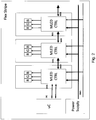
- Figure 1 shows above a microcontroller MC that communicates with an LED driver.
- the LED driver is connected to the light-emitting diodes via corresponding pins or bonds.
- several conductor tracks are necessary which connect the LED driver and the housing as well as the microcontroller MC and the control unit StW to the LED driver. This is particularly error-prone and expensive to manufacture.
- there is also the technical hurdle of integrating corresponding external assemblies into the common housing since the generation of heat from the light-emitting diodes is disadvantageous.
- the invention it was recognized that when the corresponding light-emitting diode arrangement is used in a vehicle, no heat generation that would damage such a design is to be expected.
- it is technically difficult to arrange corresponding assemblies within the housing since these are very fine structures, which is why the person skilled in the art always arranges corresponding components external to the housing.
- FIG. 2 shows control units in the form of controllers.
- the control units can be so-called multi-LED controllers. This is in the present Figure 2 marked as MLED CTRL.
- a microcontroller MC or controller is generally used to denote semiconductor chips that contain a processor and, at the same time, peripheral functions.
- the control unit StW also program control unit or control unit, is a functional unit of a processor that controls the sequence of command processing, thus loading commands, decoding and interpreting them if necessary.
- controllers and control units are different in their functional scope.
- the MLED controller takes on the task of controlling the LEDs. Since the individual MLED controllers do not have a control unit, they can only be addressed via the microcontroller.
- main controller that is to say a so-called main controller.
- main controllers these components are often not formed in one piece.
- controllers often cannot set the brightness intensity, but only the mixing ratio of the LEDs to provide a color value.
- housings are known in which the LEDs are not arranged in the housing, but protrude from it.
- Figure 2 is a plan view, a design is described here which provides that the light-emitting diodes protrude from the housing.
- FIG. 3 now shows the LED housing P according to the invention, which provides both the control unit on the right side and the individual light emitting diodes R, G and B on the left side. It is thus achieved that a single common housing P is to be provided, which protects both the light-emitting diodes and the control unit.
- the housing is a housing P which has viewing windows such that the luminous intensity of the light-emitting diodes can be perceived from outside the housing P.
- a chip housing, also referred to as package P is particularly suitable as the housing.
- control unit StW and the LED driver in one piece or, in the present view, to arrange the control unit StW above and the LED driver below. It is also possible to arrange the driver between the light-emitting diodes and the control unit StW. This again has the advantage that any geometries can be realized and thus a multitude of application scenarios is possible. In this way, a particularly compact design is created without aging processes becoming significant.
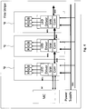
- Figure 4 shows light-emitting diodes connected in series with a separate LED driver, a separate control unit and a separate communication interface Com.
- the control unit has been moved into the housing P and, compared to known arrangements, the control unit StW, which is set up to set the brightness intensity of the light-emitting diodes LED, is arranged in one piece in the common housing P.
- a microcontroller MC it is possible for a microcontroller MC to issue a command and only respond to a selection of light-emitting diodes.
- a plurality of light-emitting diodes can thus be addressed at the same time. For example, the first and the third light-emitting diode are addressed.
- the communication interface Com receives the command in each case.
- the respective control unit recognizes whether its identification has been addressed and forwards the signal to the LED Driver.
- the first control unit recognizes that it has been addressed, decodes a brightness value and controls the LED driver in such a way that it adjusts the intensity. This also represents only one aspect of the invention.
- control unit can only calculate a control signal for the LED driver.
- the control unit can thus perform pulse width modulation and vary the amplitude.
- the color scheme of the light-emitting diode LED can be set using the mixing ratio, the brightness intensity can be set using a pulse width modulation and the brightness intensity can be set using an amplitude of the signal of the pulse width modulation.
- no peripheral functions can be provided as a controller or a microcontroller does. This creates a particularly efficient type of construction that can be provided efficiently.
- the LED drivers communicate alone and directly with the RGB LED units without the need for a controller.
- This has the advantage that the components can be manufactured separately and in a specialized manner.
- standardized LED drivers can be reused, while specialized control units StW can be installed.
- a separate control unit and a separate communication interface these can therefore be provided as separate, separate components and the respective scope of functions can be set individually. Only when they are assembled can they be arranged in one piece and thus compactly.
- Figure 5 shows a schematic flow diagram of a method for producing a compact light-emitting diode arrangement for use in a vehicle, comprising providing 100 a plurality of light-emitting diodes, a control unit 101 being provided which is set up to set the brightness intensity of the light-emitting diodes in each case, and an arrangement 102 of the provided plurality of light emitting diodes and the provided control unit takes place in one piece in a common housing.
- the control unit can be provided before the light-emitting diodes are provided.
- several light-emitting diodes can also be provided, which are arranged together with the control unit in a common housing.
- a computer program product with control commands which implement the proposed method is not shown here.
- the method can be provided as software or hardware.
Landscapes
- Engineering & Computer Science (AREA)
- Physics & Mathematics (AREA)
- Mechanical Engineering (AREA)
- Optics & Photonics (AREA)
- General Engineering & Computer Science (AREA)
- Human Computer Interaction (AREA)
- Microelectronics & Electronic Packaging (AREA)
- Multimedia (AREA)
- Computer Hardware Design (AREA)
- General Physics & Mathematics (AREA)
- Theoretical Computer Science (AREA)
- Arrangements Of Lighting Devices For Vehicle Interiors, Mounting And Supporting Thereof, Circuits Therefore (AREA)
- Led Device Packages (AREA)
Claims (13)
- Ensemble compact de diodes électroluminescentes destiné à être utilisé dans un véhicule, présentant une pluralité de diodes électroluminescentes, dans lequel les diodes électroluminescentes sont disposées en un seule pièce dans un boîtier de puce conjointement avec une unité de commande qui est conçue pour régler l'intensité lumineuse de chacune des diodes électroluminescentes, et des surfaces transparentes ou semi-transparentes ainsi que partiellement opaques sont prévues à l'intérieur du boîtier pour créer des zones de fenêtre au moyen desquelles l'intensité lumineuse de la diode électroluminescente peut être perçue de l'extérieur du boîtier, caractérisé en ce qu'une couche de vernis est prévue de telle sorte que l'unité de commande à l'intérieur du boîtier soit protégée contre l'émission des diodes électroluminescentes.
- Ensemble de diodes électroluminescentes selon la revendication 1, caractérisé en ce que l'unité de commande est installée dans le boîtier de puce conjointement avec une unité de communication et un circuit d'attaque de diodes électroluminescentes.
- Ensemble de diodes électroluminescentes selon la revendication 1 ou 2, caractérisé en ce que les diodes électroluminescentes sont activées uniquement par l'unité de commande.
- Ensemble de diodes électroluminescentes selon l'une des revendications précédentes, caractérisé en ce que des unités de mesure sont prévues dans le boîtier de puce.
- Ensemble de diodes électroluminescentes selon l'une des revendications 1 ou 3, caractérisé en ce que seules la pluralité de diodes électroluminescentes et l'unité de commande sont prévues dans le boîtier de puce en tant que composants fonctionnels actifs.
- Ensemble de diodes électroluminescentes selon l'une des revendications précédentes, caractérisé en ce que la pluralité de diodes électroluminescentes est présente sous la forme d'une diode électroluminescente rouge, d'une diode électroluminescente verte, d'une diode électroluminescente bleue et d'une diode électroluminescente blanche optionnelle.
- Composant de véhicule avec un ensemble compact de diodes électroluminescentes selon la revendication 1.
- Composant de véhicule selon la revendication 7, caractérisé en ce que le composant de véhicule est présent sous la forme d'une baguette enjoliveuse, d'un rétroviseur intérieur, d'un rétroviseur extérieur, d'un voyant d'avertissement, d'un luminaire intérieur et/ou d'un feu de véhicule.
- Composant de véhicule selon la revendication 7 ou 8, caractérisé en ce que plusieurs ensembles de diodes électroluminescentes sont connectés en série.
- Procédé de fabrication d'un ensemble compact de diodes électroluminescentes destiné à être utilisé dans un véhicule, présentant les étapes consistant à mettre à disposition une pluralité de diodes électroluminescentes, à mettre à disposition une unité de commande, qui est conçue pour régler l'intensité lumineuse de chacune des diodes électroluminescentes, et à disposer la pluralité de diodes électroluminescentes mise à disposition et l'unité de commande mise à disposition en une seule pièce dans un boîtier de puce commun, et dans lequel des surfaces transparentes ou semi-transparentes ainsi que partiellement opaques sont prévues à l'intérieur du boîtier pour créer des zones de fenêtre au moyen desquelles l'intensité lumineuse de la diode électroluminescente peut être perçue de l'extérieur du boîtier, caractérisé en ce qu'une couche de vernis est prévue de telle sorte que l'unité de commande à l'intérieur du boîtier soit protégée contre l'émission des diodes électroluminescentes.
- Procédé selon la revendication 10, caractérisé en ce que l'ensemble de diodes électroluminescentes est placé dans un composant de véhicule.
- Procédé selon la revendication 11, caractérisé en ce que le composant de véhicule est réalisé sous la forme d'une baguette enjoliveuse, d'un rétroviseur intérieur, d'un rétroviseur extérieur, d'un voyant d'avertissement, d'un luminaire intérieur et/ou d'un feu de véhicule.
- Procédé selon l'une des revendications 10 à 12, caractérisé en ce que l'étape consistant à disposer la pluralité de diodes électroluminescentes mise à disposition et de l'unité de commande mise à disposition dans le boîtier de puce est réalisée en une seule opération.
Applications Claiming Priority (2)
| Application Number | Priority Date | Filing Date | Title |
|---|---|---|---|
| DE102016014649.4A DE102016014649A1 (de) | 2016-12-08 | 2016-12-08 | Kompakte Leuchtdioden-Anordnung |
| PCT/EP2017/001349 WO2018103880A1 (fr) | 2016-12-08 | 2017-11-16 | Ensemble de diodes électroluminescentes compact |
Publications (2)
| Publication Number | Publication Date |
|---|---|
| EP3465754A1 EP3465754A1 (fr) | 2019-04-10 |
| EP3465754B1 true EP3465754B1 (fr) | 2021-01-13 |
Family
ID=60543495
Family Applications (1)
| Application Number | Title | Priority Date | Filing Date |
|---|---|---|---|
| EP17808003.2A Active EP3465754B1 (fr) | 2016-12-08 | 2017-11-16 | Ensemble de diodes électroluminescentes compact |
Country Status (11)
| Country | Link |
|---|---|
| US (1) | US10688926B2 (fr) |
| EP (1) | EP3465754B1 (fr) |
| JP (1) | JP6595133B2 (fr) |
| KR (1) | KR102111897B1 (fr) |
| CN (1) | CN109417069B (fr) |
| CA (1) | CA3028830C (fr) |
| DE (1) | DE102016014649A1 (fr) |
| ES (1) | ES2856084T3 (fr) |
| MY (1) | MY177782A (fr) |
| SG (1) | SG11201811486TA (fr) |
| WO (1) | WO2018103880A1 (fr) |
Families Citing this family (10)
| Publication number | Priority date | Publication date | Assignee | Title |
|---|---|---|---|---|
| DE102016014649A1 (de) | 2016-12-08 | 2018-06-14 | Inova Semiconductors Gmbh | Kompakte Leuchtdioden-Anordnung |
| DE102018010305C5 (de) | 2018-09-10 | 2026-02-19 | Inova Semiconductors Gmbh | Segmentierte Steuerungsanordnung |
| DE102018007143B4 (de) | 2018-09-10 | 2019-10-10 | Inova Semiconductors Gmbh | Effiziente Leitungstreibervorrichtung zur Datenflusskontrolle |
| DE102018007144B4 (de) | 2018-09-10 | 2019-10-10 | Inova Semiconductors Gmbh | Leitungstreibervorrichtung zur Datenflusskontrolle |
| DE102018010311B3 (de) | 2018-09-10 | 2019-12-05 | Inova Semiconductors Gmbh | Effiziente Leitungstreibervorrichtung zur Datenflusskontrolle |
| DE202018006224U1 (de) | 2018-09-10 | 2019-08-28 | Inova Semiconductors Gmbh | Effiziente Leitungstreibervorrichtung zur Datenflusskontrolle |
| DE102018010307B4 (de) | 2018-09-10 | 2020-01-09 | Inova Semiconductors Gmbh | Segmentierte Steuerungsanordnung |
| DE102018007141C5 (de) | 2018-09-10 | 2025-05-15 | Inova Semiconductors Gmbh | Segmentierte Steuerungsanordnung |
| TWI696785B (zh) * | 2019-01-11 | 2020-06-21 | 億光電子工業股份有限公司 | 用於移動載具之照明裝置 |
| DE102019002119B4 (de) | 2019-03-25 | 2020-06-10 | Inova Semiconductors Gmbh | Ansteuern von Ausführungseinheiten |
Citations (4)
| Publication number | Priority date | Publication date | Assignee | Title |
|---|---|---|---|---|
| WO2008025625A1 (fr) * | 2006-08-30 | 2008-03-06 | Robert Bosch Gmbh | Module luminescent |
| US20090021955A1 (en) * | 2007-07-17 | 2009-01-22 | I/O Controls Corporation | Control network for led-based lighting system in a transit vehicle |
| WO2009140947A2 (fr) * | 2008-05-23 | 2009-11-26 | Osram Opto Semiconductors Gmbh | Module optoélectronique |
| DE102011004746A1 (de) * | 2011-02-25 | 2012-08-30 | Osram Ag | Halbleiter-Leuchtmodul und Fahrzeugleuchte |
Family Cites Families (22)
| Publication number | Priority date | Publication date | Assignee | Title |
|---|---|---|---|---|
| JP2001093305A (ja) * | 1999-09-28 | 2001-04-06 | Toyoda Gosei Co Ltd | 照明装置 |
| US6885035B2 (en) * | 1999-12-22 | 2005-04-26 | Lumileds Lighting U.S., Llc | Multi-chip semiconductor LED assembly |
| PT1422975E (pt) * | 2000-04-24 | 2010-07-09 | Philips Solid State Lighting | Produto base de leds |
| JP2005053381A (ja) * | 2003-08-06 | 2005-03-03 | Mitsubishi Motors Corp | 車両用ヘッドランプの配光制御装置 |
| US20070031631A1 (en) * | 2005-08-04 | 2007-02-08 | Imation Corp. | Ultra-violet protection of data storage media |
| JP5207812B2 (ja) * | 2008-04-25 | 2013-06-12 | 京セラ株式会社 | 発光デバイスおよび発光デバイスの製造方法 |
| US9056584B2 (en) * | 2010-07-08 | 2015-06-16 | Gentex Corporation | Rearview assembly for a vehicle |
| DE102011009108A1 (de) * | 2011-01-21 | 2012-07-26 | Diehl Aerospace Gmbh | Leuchtmittel |
| TWI444088B (zh) * | 2011-03-11 | 2014-07-01 | Nat Univ Tsing Hua | 不具色分離現象之彩色發光二極體顯示裝置 |
| KR20120124840A (ko) * | 2011-05-04 | 2012-11-14 | 삼성전자주식회사 | 발광 다이오드 구동 장치 및 발광 다이오드 구동 방법 |
| US20130134898A1 (en) * | 2011-11-29 | 2013-05-30 | International Business Machines Corporation | Light Emitting Diode Producing Any Desired Color |
| JP2013200442A (ja) * | 2012-03-26 | 2013-10-03 | Nippon Seiki Co Ltd | 表示装置 |
| US9431369B2 (en) * | 2012-12-13 | 2016-08-30 | Taiwan Semiconductor Manufacturing Company, Ltd. | Antenna apparatus and method |
| DE102013210261B4 (de) * | 2013-06-03 | 2018-03-22 | Lisa Dräxlmaier GmbH | Beleuchtungsvorrichtung für ein Fahrzeug |
| US9362234B2 (en) * | 2014-01-07 | 2016-06-07 | Freescale Semiconductor, Inc. | Shielded device packages having antennas and related fabrication methods |
| WO2015177047A1 (fr) * | 2014-05-19 | 2015-11-26 | Styrolution Group Gmbh | Film composite de copolymère de styrène |
| US9991163B2 (en) * | 2014-09-25 | 2018-06-05 | X-Celeprint Limited | Small-aperture-ratio display with electrical component |
| US9818725B2 (en) * | 2015-06-01 | 2017-11-14 | X-Celeprint Limited | Inorganic-light-emitter display with integrated black matrix |
| JP2016122731A (ja) * | 2014-12-25 | 2016-07-07 | ローム株式会社 | 光半導体装置およびその製造方法 |
| US11195787B2 (en) * | 2016-02-17 | 2021-12-07 | Infineon Technologies Ag | Semiconductor device including an antenna |
| DE102016014649A1 (de) | 2016-12-08 | 2018-06-14 | Inova Semiconductors Gmbh | Kompakte Leuchtdioden-Anordnung |
| CN108511400B (zh) * | 2018-03-16 | 2023-10-03 | 盛合晶微半导体(江阴)有限公司 | 天线的封装结构及封装方法 |
-
2016
- 2016-12-08 DE DE102016014649.4A patent/DE102016014649A1/de active Pending
-
2017
- 2017-11-16 CA CA3028830A patent/CA3028830C/fr active Active
- 2017-11-16 WO PCT/EP2017/001349 patent/WO2018103880A1/fr not_active Ceased
- 2017-11-16 ES ES17808003T patent/ES2856084T3/es active Active
- 2017-11-16 US US16/467,894 patent/US10688926B2/en active Active
- 2017-11-16 KR KR1020197001657A patent/KR102111897B1/ko active Active
- 2017-11-16 JP JP2018568400A patent/JP6595133B2/ja active Active
- 2017-11-16 SG SG11201811486TA patent/SG11201811486TA/en unknown
- 2017-11-16 EP EP17808003.2A patent/EP3465754B1/fr active Active
- 2017-11-16 MY MYPI2019002882A patent/MY177782A/en unknown
- 2017-11-16 CN CN201780039909.XA patent/CN109417069B/zh active Active
Patent Citations (4)
| Publication number | Priority date | Publication date | Assignee | Title |
|---|---|---|---|---|
| WO2008025625A1 (fr) * | 2006-08-30 | 2008-03-06 | Robert Bosch Gmbh | Module luminescent |
| US20090021955A1 (en) * | 2007-07-17 | 2009-01-22 | I/O Controls Corporation | Control network for led-based lighting system in a transit vehicle |
| WO2009140947A2 (fr) * | 2008-05-23 | 2009-11-26 | Osram Opto Semiconductors Gmbh | Module optoélectronique |
| DE102011004746A1 (de) * | 2011-02-25 | 2012-08-30 | Osram Ag | Halbleiter-Leuchtmodul und Fahrzeugleuchte |
Also Published As
| Publication number | Publication date |
|---|---|
| KR20190020075A (ko) | 2019-02-27 |
| CN109417069B (zh) | 2022-09-27 |
| CA3028830A1 (fr) | 2018-06-14 |
| CN109417069A (zh) | 2019-03-01 |
| JP2019523548A (ja) | 2019-08-22 |
| JP6595133B2 (ja) | 2019-10-23 |
| CA3028830C (fr) | 2020-10-27 |
| SG11201811486TA (en) | 2019-01-30 |
| US20200070720A1 (en) | 2020-03-05 |
| WO2018103880A1 (fr) | 2018-06-14 |
| US10688926B2 (en) | 2020-06-23 |
| DE102016014649A1 (de) | 2018-06-14 |
| KR102111897B1 (ko) | 2020-05-15 |
| EP3465754A1 (fr) | 2019-04-10 |
| MY177782A (en) | 2020-09-23 |
| ES2856084T3 (es) | 2021-09-27 |
Similar Documents
| Publication | Publication Date | Title |
|---|---|---|
| EP3465754B1 (fr) | Ensemble de diodes électroluminescentes compact | |
| WO2017153026A1 (fr) | Procédé et dispositif de compensation de luminosité d'une led | |
| EP4236631B1 (fr) | Agencement de commande segmenté | |
| EP3453229A1 (fr) | Dispositif d'éclairage | |
| EP2469596A2 (fr) | Module d'éclairage pour un dispositif d'éclairage d'un véhicule automobile doté de sources lumineuses semi-conductrices agencées sur un substrat de silicium | |
| EP2695010A2 (fr) | Élément carte de circuit imprimé doté d'au moins une del | |
| DE102015118497A1 (de) | Beleuchtungsvorrichtung für ein fahrzeug und verfahren zur beleuchtung eines fahrzeugs | |
| EP3707967B1 (fr) | Méthode et appareil pour ajuster une longueur d'ondes constante | |
| EP2765445A1 (fr) | Unité à LED avec lentille | |
| DE102017127597A1 (de) | Optoelektronisches bauelement und verfahren zum herstellen eines optoelektronischen bauelements | |
| EP3466756B1 (fr) | Conduit de lumière en cascade pouvant être animé | |
| WO2026037601A1 (fr) | Dispositif optoélectronique et procédé de fonctionnement de dispositif optoélectronique | |
| EP2394372B1 (fr) | Dispositif d'éclairage | |
| DE102007052854A1 (de) | Verfahren und Vorrichtung zur Steuerung der Lichtabgabe einer LED-Leuchte | |
| DE102009031403A1 (de) | Leuchtelement, Leuchte und Verfahren zum Betrieb des Leuchtelements | |
| WO2020208080A1 (fr) | Composant optoélectronique, système et son procédé de fabrication | |
| DE102016105491A1 (de) | Herstellung von halbleiterbauelementen | |
| DE102022001884B4 (de) | Scheibenbaugruppe für ein Kraftfahrzeug | |
| EP3873778B1 (fr) | Procédé de fabrication d'un ensemble de sources lumineuses et ensemble de sources lumineuses fabriqué selon un tel procédé | |
| EP2473007B1 (fr) | Module DEL pour la stabilisation passive du flux lumineux | |
| DE102018010305B4 (de) | Segmentierte Steuerungsanordnung | |
| DE102018010307B4 (de) | Segmentierte Steuerungsanordnung | |
| WO2018172173A1 (fr) | Ensemble électroluminescent comprenant un élément semi-conducteur électroluminescent | |
| WO2022128820A1 (fr) | Dispositif optoélectronique, ensemble d'éclairage et courroie de placement | |
| WO2017190979A1 (fr) | Dispositif d'éclairage |
Legal Events
| Date | Code | Title | Description |
|---|---|---|---|
| STAA | Information on the status of an ep patent application or granted ep patent |
Free format text: STATUS: UNKNOWN |
|
| STAA | Information on the status of an ep patent application or granted ep patent |
Free format text: STATUS: THE INTERNATIONAL PUBLICATION HAS BEEN MADE |
|
| PUAI | Public reference made under article 153(3) epc to a published international application that has entered the european phase |
Free format text: ORIGINAL CODE: 0009012 |
|
| STAA | Information on the status of an ep patent application or granted ep patent |
Free format text: STATUS: REQUEST FOR EXAMINATION WAS MADE |
|
| 17P | Request for examination filed |
Effective date: 20190102 |
|
| AK | Designated contracting states |
Kind code of ref document: A1 Designated state(s): AL AT BE BG CH CY CZ DE DK EE ES FI FR GB GR HR HU IE IS IT LI LT LU LV MC MK MT NL NO PL PT RO RS SE SI SK SM TR |
|
| AX | Request for extension of the european patent |
Extension state: BA ME |
|
| DAV | Request for validation of the european patent (deleted) | ||
| DAX | Request for extension of the european patent (deleted) | ||
| GRAP | Despatch of communication of intention to grant a patent |
Free format text: ORIGINAL CODE: EPIDOSNIGR1 |
|
| STAA | Information on the status of an ep patent application or granted ep patent |
Free format text: STATUS: GRANT OF PATENT IS INTENDED |
|
| GRAS | Grant fee paid |
Free format text: ORIGINAL CODE: EPIDOSNIGR3 |
|
| INTG | Intention to grant announced |
Effective date: 20201026 |
|
| GRAA | (expected) grant |
Free format text: ORIGINAL CODE: 0009210 |
|
| STAA | Information on the status of an ep patent application or granted ep patent |
Free format text: STATUS: THE PATENT HAS BEEN GRANTED |
|
| AK | Designated contracting states |
Kind code of ref document: B1 Designated state(s): AL AT BE BG CH CY CZ DE DK EE ES FI FR GB GR HR HU IE IS IT LI LT LU LV MC MK MT NL NO PL PT RO RS SE SI SK SM TR |
|
| REG | Reference to a national code |
Ref country code: GB Ref legal event code: FG4D Free format text: NOT ENGLISH |
|
| REG | Reference to a national code |
Ref country code: CH Ref legal event code: EP |
|
| REG | Reference to a national code |
Ref country code: IE Ref legal event code: FG4D Free format text: LANGUAGE OF EP DOCUMENT: GERMAN |
|
| REG | Reference to a national code |
Ref country code: DE Ref legal event code: R096 Ref document number: 502017009084 Country of ref document: DE |
|
| REG | Reference to a national code |
Ref country code: AT Ref legal event code: REF Ref document number: 1355185 Country of ref document: AT Kind code of ref document: T Effective date: 20210215 |
|
| REG | Reference to a national code |
Ref country code: SE Ref legal event code: TRGR |
|
| REG | Reference to a national code |
Ref country code: NL Ref legal event code: FP |
|
| REG | Reference to a national code |
Ref country code: LT Ref legal event code: MG9D |
|
| PG25 | Lapsed in a contracting state [announced via postgrant information from national office to epo] |
Ref country code: BG Free format text: LAPSE BECAUSE OF FAILURE TO SUBMIT A TRANSLATION OF THE DESCRIPTION OR TO PAY THE FEE WITHIN THE PRESCRIBED TIME-LIMIT Effective date: 20210413 Ref country code: LT Free format text: LAPSE BECAUSE OF FAILURE TO SUBMIT A TRANSLATION OF THE DESCRIPTION OR TO PAY THE FEE WITHIN THE PRESCRIBED TIME-LIMIT Effective date: 20210113 Ref country code: NO Free format text: LAPSE BECAUSE OF FAILURE TO SUBMIT A TRANSLATION OF THE DESCRIPTION OR TO PAY THE FEE WITHIN THE PRESCRIBED TIME-LIMIT Effective date: 20210413 Ref country code: PT Free format text: LAPSE BECAUSE OF FAILURE TO SUBMIT A TRANSLATION OF THE DESCRIPTION OR TO PAY THE FEE WITHIN THE PRESCRIBED TIME-LIMIT Effective date: 20210513 Ref country code: FI Free format text: LAPSE BECAUSE OF FAILURE TO SUBMIT A TRANSLATION OF THE DESCRIPTION OR TO PAY THE FEE WITHIN THE PRESCRIBED TIME-LIMIT Effective date: 20210113 Ref country code: HR Free format text: LAPSE BECAUSE OF FAILURE TO SUBMIT A TRANSLATION OF THE DESCRIPTION OR TO PAY THE FEE WITHIN THE PRESCRIBED TIME-LIMIT Effective date: 20210113 Ref country code: GR Free format text: LAPSE BECAUSE OF FAILURE TO SUBMIT A TRANSLATION OF THE DESCRIPTION OR TO PAY THE FEE WITHIN THE PRESCRIBED TIME-LIMIT Effective date: 20210414 |
|
| PG25 | Lapsed in a contracting state [announced via postgrant information from national office to epo] |
Ref country code: PL Free format text: LAPSE BECAUSE OF FAILURE TO SUBMIT A TRANSLATION OF THE DESCRIPTION OR TO PAY THE FEE WITHIN THE PRESCRIBED TIME-LIMIT Effective date: 20210113 Ref country code: LV Free format text: LAPSE BECAUSE OF FAILURE TO SUBMIT A TRANSLATION OF THE DESCRIPTION OR TO PAY THE FEE WITHIN THE PRESCRIBED TIME-LIMIT Effective date: 20210113 Ref country code: RS Free format text: LAPSE BECAUSE OF FAILURE TO SUBMIT A TRANSLATION OF THE DESCRIPTION OR TO PAY THE FEE WITHIN THE PRESCRIBED TIME-LIMIT Effective date: 20210113 |
|
| REG | Reference to a national code |
Ref country code: ES Ref legal event code: FG2A Ref document number: 2856084 Country of ref document: ES Kind code of ref document: T3 Effective date: 20210927 |
|
| PG25 | Lapsed in a contracting state [announced via postgrant information from national office to epo] |
Ref country code: IS Free format text: LAPSE BECAUSE OF FAILURE TO SUBMIT A TRANSLATION OF THE DESCRIPTION OR TO PAY THE FEE WITHIN THE PRESCRIBED TIME-LIMIT Effective date: 20210513 |
|
| REG | Reference to a national code |
Ref country code: DE Ref legal event code: R097 Ref document number: 502017009084 Country of ref document: DE |
|
| PG25 | Lapsed in a contracting state [announced via postgrant information from national office to epo] |
Ref country code: EE Free format text: LAPSE BECAUSE OF FAILURE TO SUBMIT A TRANSLATION OF THE DESCRIPTION OR TO PAY THE FEE WITHIN THE PRESCRIBED TIME-LIMIT Effective date: 20210113 Ref country code: CZ Free format text: LAPSE BECAUSE OF FAILURE TO SUBMIT A TRANSLATION OF THE DESCRIPTION OR TO PAY THE FEE WITHIN THE PRESCRIBED TIME-LIMIT Effective date: 20210113 Ref country code: SM Free format text: LAPSE BECAUSE OF FAILURE TO SUBMIT A TRANSLATION OF THE DESCRIPTION OR TO PAY THE FEE WITHIN THE PRESCRIBED TIME-LIMIT Effective date: 20210113 |
|
| PLBE | No opposition filed within time limit |
Free format text: ORIGINAL CODE: 0009261 |
|
| STAA | Information on the status of an ep patent application or granted ep patent |
Free format text: STATUS: NO OPPOSITION FILED WITHIN TIME LIMIT |
|
| PG25 | Lapsed in a contracting state [announced via postgrant information from national office to epo] |
Ref country code: DK Free format text: LAPSE BECAUSE OF FAILURE TO SUBMIT A TRANSLATION OF THE DESCRIPTION OR TO PAY THE FEE WITHIN THE PRESCRIBED TIME-LIMIT Effective date: 20210113 Ref country code: SK Free format text: LAPSE BECAUSE OF FAILURE TO SUBMIT A TRANSLATION OF THE DESCRIPTION OR TO PAY THE FEE WITHIN THE PRESCRIBED TIME-LIMIT Effective date: 20210113 Ref country code: RO Free format text: LAPSE BECAUSE OF FAILURE TO SUBMIT A TRANSLATION OF THE DESCRIPTION OR TO PAY THE FEE WITHIN THE PRESCRIBED TIME-LIMIT Effective date: 20210113 |
|
| 26N | No opposition filed |
Effective date: 20211014 |
|
| PG25 | Lapsed in a contracting state [announced via postgrant information from national office to epo] |
Ref country code: AL Free format text: LAPSE BECAUSE OF FAILURE TO SUBMIT A TRANSLATION OF THE DESCRIPTION OR TO PAY THE FEE WITHIN THE PRESCRIBED TIME-LIMIT Effective date: 20210113 |
|
| PG25 | Lapsed in a contracting state [announced via postgrant information from national office to epo] |
Ref country code: SI Free format text: LAPSE BECAUSE OF FAILURE TO SUBMIT A TRANSLATION OF THE DESCRIPTION OR TO PAY THE FEE WITHIN THE PRESCRIBED TIME-LIMIT Effective date: 20210113 |
|
| PG25 | Lapsed in a contracting state [announced via postgrant information from national office to epo] |
Ref country code: IS Free format text: LAPSE BECAUSE OF FAILURE TO SUBMIT A TRANSLATION OF THE DESCRIPTION OR TO PAY THE FEE WITHIN THE PRESCRIBED TIME-LIMIT Effective date: 20210513 |
|
| PG25 | Lapsed in a contracting state [announced via postgrant information from national office to epo] |
Ref country code: MC Free format text: LAPSE BECAUSE OF FAILURE TO SUBMIT A TRANSLATION OF THE DESCRIPTION OR TO PAY THE FEE WITHIN THE PRESCRIBED TIME-LIMIT Effective date: 20210113 |
|
| REG | Reference to a national code |
Ref country code: CH Ref legal event code: PL |
|
| PG25 | Lapsed in a contracting state [announced via postgrant information from national office to epo] |
Ref country code: LU Free format text: LAPSE BECAUSE OF NON-PAYMENT OF DUE FEES Effective date: 20211116 Ref country code: BE Free format text: LAPSE BECAUSE OF NON-PAYMENT OF DUE FEES Effective date: 20211130 |
|
| REG | Reference to a national code |
Ref country code: BE Ref legal event code: MM Effective date: 20211130 |
|
| PG25 | Lapsed in a contracting state [announced via postgrant information from national office to epo] |
Ref country code: IE Free format text: LAPSE BECAUSE OF NON-PAYMENT OF DUE FEES Effective date: 20211116 |
|
| PG25 | Lapsed in a contracting state [announced via postgrant information from national office to epo] |
Ref country code: CY Free format text: LAPSE BECAUSE OF FAILURE TO SUBMIT A TRANSLATION OF THE DESCRIPTION OR TO PAY THE FEE WITHIN THE PRESCRIBED TIME-LIMIT Effective date: 20210113 |
|
| PG25 | Lapsed in a contracting state [announced via postgrant information from national office to epo] |
Ref country code: LI Free format text: LAPSE BECAUSE OF NON-PAYMENT OF DUE FEES Effective date: 20220630 Ref country code: HU Free format text: LAPSE BECAUSE OF FAILURE TO SUBMIT A TRANSLATION OF THE DESCRIPTION OR TO PAY THE FEE WITHIN THE PRESCRIBED TIME-LIMIT; INVALID AB INITIO Effective date: 20171116 Ref country code: CH Free format text: LAPSE BECAUSE OF NON-PAYMENT OF DUE FEES Effective date: 20220630 |
|
| P01 | Opt-out of the competence of the unified patent court (upc) registered |
Effective date: 20230912 |
|
| REG | Reference to a national code |
Ref country code: AT Ref legal event code: MM01 Ref document number: 1355185 Country of ref document: AT Kind code of ref document: T Effective date: 20221116 |
|
| PG25 | Lapsed in a contracting state [announced via postgrant information from national office to epo] |
Ref country code: AT Free format text: LAPSE BECAUSE OF NON-PAYMENT OF DUE FEES Effective date: 20221116 |
|
| PG25 | Lapsed in a contracting state [announced via postgrant information from national office to epo] |
Ref country code: MK Free format text: LAPSE BECAUSE OF FAILURE TO SUBMIT A TRANSLATION OF THE DESCRIPTION OR TO PAY THE FEE WITHIN THE PRESCRIBED TIME-LIMIT Effective date: 20210113 |
|
| PG25 | Lapsed in a contracting state [announced via postgrant information from national office to epo] |
Ref country code: MT Free format text: LAPSE BECAUSE OF FAILURE TO SUBMIT A TRANSLATION OF THE DESCRIPTION OR TO PAY THE FEE WITHIN THE PRESCRIBED TIME-LIMIT Effective date: 20210113 |
|
| REG | Reference to a national code |
Ref country code: DE Ref legal event code: R079 Ref document number: 502017009084 Country of ref document: DE Free format text: PREVIOUS MAIN CLASS: H01L0025075000 Ipc: H10H0029240000 |
|
| PG25 | Lapsed in a contracting state [announced via postgrant information from national office to epo] |
Ref country code: TR Free format text: LAPSE BECAUSE OF FAILURE TO SUBMIT A TRANSLATION OF THE DESCRIPTION OR TO PAY THE FEE WITHIN THE PRESCRIBED TIME-LIMIT Effective date: 20210113 |
|
| PGFP | Annual fee paid to national office [announced via postgrant information from national office to epo] |
Ref country code: NL Payment date: 20251119 Year of fee payment: 9 |
|
| PGFP | Annual fee paid to national office [announced via postgrant information from national office to epo] |
Ref country code: DE Payment date: 20251118 Year of fee payment: 9 |
|
| PGFP | Annual fee paid to national office [announced via postgrant information from national office to epo] |
Ref country code: GB Payment date: 20251120 Year of fee payment: 9 |
|
| PGFP | Annual fee paid to national office [announced via postgrant information from national office to epo] |
Ref country code: IT Payment date: 20251128 Year of fee payment: 9 |
|
| PGFP | Annual fee paid to national office [announced via postgrant information from national office to epo] |
Ref country code: FR Payment date: 20251120 Year of fee payment: 9 |
|
| PGFP | Annual fee paid to national office [announced via postgrant information from national office to epo] |
Ref country code: SE Payment date: 20251119 Year of fee payment: 9 |
|
| PGFP | Annual fee paid to national office [announced via postgrant information from national office to epo] |
Ref country code: ES Payment date: 20251216 Year of fee payment: 9 |