EP3466367A1 - Système de stockage pour instruments médicaux - Google Patents
Système de stockage pour instruments médicaux Download PDFInfo
- Publication number
- EP3466367A1 EP3466367A1 EP18204465.1A EP18204465A EP3466367A1 EP 3466367 A1 EP3466367 A1 EP 3466367A1 EP 18204465 A EP18204465 A EP 18204465A EP 3466367 A1 EP3466367 A1 EP 3466367A1
- Authority
- EP
- European Patent Office
- Prior art keywords
- receiving sleeve
- receiving
- hollow body
- tool
- matrix
- Prior art date
- Legal status (The legal status is an assumption and is not a legal conclusion. Google has not performed a legal analysis and makes no representation as to the accuracy of the status listed.)
- Granted
Links
Images


Classifications
-
- A—HUMAN NECESSITIES
- A61—MEDICAL OR VETERINARY SCIENCE; HYGIENE
- A61C—DENTISTRY; APPARATUS OR METHODS FOR ORAL OR DENTAL HYGIENE
- A61C3/00—Dental tools or instruments
- A61C3/04—Supports for holding tooth drills in order of use
-
- A—HUMAN NECESSITIES
- A61—MEDICAL OR VETERINARY SCIENCE; HYGIENE
- A61B—DIAGNOSIS; SURGERY; IDENTIFICATION
- A61B50/00—Containers, covers, furniture or holders specially adapted for surgical or diagnostic appliances or instruments, e.g. sterile covers
- A61B50/20—Holders specially adapted for surgical or diagnostic appliances or instruments
-
- A—HUMAN NECESSITIES
- A61—MEDICAL OR VETERINARY SCIENCE; HYGIENE
- A61B—DIAGNOSIS; SURGERY; IDENTIFICATION
- A61B50/00—Containers, covers, furniture or holders specially adapted for surgical or diagnostic appliances or instruments, e.g. sterile covers
- A61B50/30—Containers specially adapted for packaging, protecting, dispensing, collecting or disposing of surgical or diagnostic appliances or instruments
-
- A—HUMAN NECESSITIES
- A61—MEDICAL OR VETERINARY SCIENCE; HYGIENE
- A61B—DIAGNOSIS; SURGERY; IDENTIFICATION
- A61B50/00—Containers, covers, furniture or holders specially adapted for surgical or diagnostic appliances or instruments, e.g. sterile covers
- A61B50/30—Containers specially adapted for packaging, protecting, dispensing, collecting or disposing of surgical or diagnostic appliances or instruments
- A61B50/34—Baskets
-
- A—HUMAN NECESSITIES
- A61—MEDICAL OR VETERINARY SCIENCE; HYGIENE
- A61C—DENTISTRY; APPARATUS OR METHODS FOR ORAL OR DENTAL HYGIENE
- A61C19/00—Dental auxiliary appliances
- A61C19/02—Protective casings, e.g. boxes for instruments; Bags
-
- A—HUMAN NECESSITIES
- A61—MEDICAL OR VETERINARY SCIENCE; HYGIENE
- A61B—DIAGNOSIS; SURGERY; IDENTIFICATION
- A61B50/00—Containers, covers, furniture or holders specially adapted for surgical or diagnostic appliances or instruments, e.g. sterile covers
- A61B2050/005—Containers, covers, furniture or holders specially adapted for surgical or diagnostic appliances or instruments, e.g. sterile covers with a lid or cover
- A61B2050/0058—Containers, covers, furniture or holders specially adapted for surgical or diagnostic appliances or instruments, e.g. sterile covers with a lid or cover closable by translation
- A61B2050/006—Containers, covers, furniture or holders specially adapted for surgical or diagnostic appliances or instruments, e.g. sterile covers with a lid or cover closable by translation perpendicular to the lid plane, e.g. by a downward movement
-
- A—HUMAN NECESSITIES
- A61—MEDICAL OR VETERINARY SCIENCE; HYGIENE
- A61B—DIAGNOSIS; SURGERY; IDENTIFICATION
- A61B50/00—Containers, covers, furniture or holders specially adapted for surgical or diagnostic appliances or instruments, e.g. sterile covers
- A61B2050/005—Containers, covers, furniture or holders specially adapted for surgical or diagnostic appliances or instruments, e.g. sterile covers with a lid or cover
- A61B2050/0067—Types of closures or fasteners
- A61B2050/0074—Toggle latches or clamps
Definitions
- the present invention relates to a storage system for medical instruments, in particular dental instruments, according to the preamble of patent claim 1.
- Drilling or milling heads are used, each on / in a instrument drive comprehensive handpiece removably on / can be plugged. This allows the surgeon, during operation of the handpiece, to change the instrument head inserted / inserted on the handpiece, depending on the requirements of the application.
- the tools are usually kept sorted in a surgical tool set.
- the tools are not loosely stored, but added to receiving sleeves, which are inserted in a hole matrix of the tool set or fixed therein.
- the receiving sleeves are often color-coded.
- a template with printed surgical paths can be placed on the receptacles to further simplify the selection of the required tool.
- Surgical tools in particular dental tools or lathe tools of this type have a distal tool engaging portion and a proximal shaft portion, wherein receiving sleeves with different diameters of the werkzugmethodö Maschinenen allow the correct and precise fit of tools with different shaft diameters. Furthermore, the receiving sleeves are color-coded for a simpler finding a required tool by a surgeon, preferably a printed template provided sit, which can be placed over the receptacles and printed with surgical paths and names of each recorded in one of the receptacles tools.
- the amount of time involved is very large and the many steps in the cleaning process (disassembly into parts, cleaning of each part) provide many opportunities for damage to the tool set or user errors in cleaning. Since due to the massive structure of the receiving sleeves cleaning liquids can hardly penetrate into the receiving opening of the receiving sleeves, if necessary, a manual post-cleaning of the receiving openings must be performed.
- plastic components of conventional tool sets must be made of special temperature-resistant plastic, which increases the manufacturing costs.
- soiling of plastic often lasts longer than on other materials such as metal, which makes cleaning the tool set even more difficult.
- the massive structure of conventional tool sets and their plastic manufacturing material proves to be disadvantageous.
- tool sets and receiving sleeves for surgical instruments are known from the prior art, which do not allow a cleaning of the recorded surgical instruments in fitted state of the tool set (storage box) due to the massive structure of the receptacles and tool sets.
- the invention has for its object to provide a receiving sleeve, as well as a holding device for this receiving sleeve and a surgical instrument set, the efficient and simplified cleaning of the tool set, preferably in the assembled state, and the surgical contained therein Instruments, enable.
- a basic idea of the invention is essentially that both the receiving sleeve and the entire tool set (or receiving box with sleeve-holding device and receiving sleeve) by a filigree design as permeable as possible for cleaning or drying fluid, so that as much cleaning or Drying fluid can reach the tools included in the tool set.
- Another basic idea of the invention consists essentially in the use of the receiving sleeves inserted in the tool set with a type of inner tool holder provided, which holds the inserted tool substantially point or line, so that between inserted tool and receiving sleeve (radial) free spaces remain that can be used for large-scale flow around the inserted tool with cleaning fluid.
- the core of the present invention is accordingly, the receiving sleeve, and the components of the receiving sleeve supporting the support device and the holding device receiving tool set (box), in which the receiving sleeve is inserted, and possibly any additional additional parts of the tool set according to the invention (in filigree - / Gerüstbauweise) as a broken body of light construction, so as to ensure a circumferential permeability to cleaning fluids and to produce only small contact surfaces with the tool.
- a light construction is understood to be a construction of a body / box in which the body / box has as many recesses as possible and as much as possible breaks through.
- a solid construction is understood to mean a construction of a body / box in which the body / box has few to no recesses and therefore has little or no break through.
- the term "light structure" is preferably defined in that the total area of the openings / gaps in the receiving sleeve / in the box is greater than the total area covered by the sleeve / box material.
- the receiving sleeve thus consists of a body of light construction (scaffold construction) according to the above definition in the form of a Hollow cylinder / hollow body having an axial tool receiving / insertion at a first axial end into which surgical tools can be inserted, wherein the hollow cylinder / hollow body of the receiving sleeve is adapted to minimize the contact surface between receiving sleeve and a tool received therein and a maximum fluid flow (radial) through the hollow body of the receiving sleeve and to allow the recorded in the receiving sleeve tool.
- the receiving sleeve is in this case in one piece z. B. by injection molding or by the rapid prototyping method (sintering method) made of a plastic and is characterized by a possible flat surface without gaps or undercuts to counteract a deposition of contaminants.
- the receiving sleeve has on its inside a number of elastically deformable projections (or clamping arms / retaining claws), which preferably form a funnel inside the hollow cylinder of the receiving sleeve, which narrows in the insertion direction of a male tool.
- elastically deformable projections or clamping arms / retaining claws
- the diameter of the radially limited by the clamping arms cavity is radially expanded and the clamping arms are resiliently pressed in the radial direction to the outside.
- the inserted tool is clamped in the cavity of the hollow cylinder between the clamping arms.
- the clamping arms are preferably designed so that the contact surface between clamp arms and recorded tool is as low as possible (line and / or punctiform). Since the surface of the tool forms a contact point with the hollow body of the receiving sleeve only at the points / lines defined by the clamping arms, the majority of the surface of the portion of the tool accommodated in the receiving sleeve is not in contact with the hollow body of the receiving sleeve and is thus of Cleaning fluid can be rinsed.
- the clamping arms on the inside of the receiving sleeve are not formed integrally with the hollow body of the receiving sleeve, but separately, for example, made of metal and embedded in the hollow body of the receiving sleeve. Such production of the clamping arms has an advantageous effect on the life and robustness of the receiving sleeve.
- the receiving sleeve has on its inside a number of rigid, axially extending projections (or axially extending guide arms / longitudinal ribs), which preferably form a funnel within the hollow cylinder / hollow body of the receiving sleeve, which narrows in the insertion direction of a male tool ,
- the projections / guide arms additionally form a collecting base (stop) in the hollow cylinder at another end portion (opposite the insertion opening) of the receiving sleeve in order to prevent too deep insertion of a tool into the receiving sleeve.
- a receiving sleeve according to the invention may have only a number of Leitarmen, only a number of clamping arms or even a combination of control and clamping arms.
- the receiving sleeve can be inserted into a holding device preferably consisting of two parallel spaced perforated plates or matrices and firmly anchored therein, the receiving sleeve in one embodiment of the invention on its outer side (shell side) at least one elastically deformable radially projecting projection or retaining wedge. If the receiving sleeve is inserted, for example, in a hole of the holding device (hole matrix / perforated plate), then the projection / retaining wedge is pressed inwards by the limitation of the hole in the radial direction of the hollow cylinder.
- the receiving sleeve in the hole of the hole matrix is then held in position by the projection with complete axial insertion of the receiving sleeve into the holding device (perforated plate) the projection behind the hole the holding device (perforated plate) applies and thus axially against the mounting device (hole matrix / perforated plate) is supported.
- this additionally comprises a circumferential annular projection (collar) along the circumference of the hollow cylinder in the region of the insertion and at the axial distance to the retaining wedge, which rests in the inserted state of the receiving sleeve in the holding device on a hole matrix preferably with round holes and thus prevents unwanted movement of the receiving sleeve in the insertion direction and a passing / pushing through the receiving sleeve through a round hole of the matrix.
- the fixture / hole matrix between the collar and the retaining wedge is axially fixed.
- the circumferential projection is flattened on its side facing the insertion opening of the receiving sleeve so that a printed stencil can be placed in a form-fitting manner on the flattened side of the annular projection.
- the circumferential annular projection on its side facing away from the insertion of the receiving sleeve side recesses / axial projections whereby the axial contact area between the collar and the matrix of the support device is reduced and any dirt that collects between receiving sleeve and mounting device, efficiently washed away by cleaning fluid can be.
- a holding device comprises, for example, a first hole matrix (perforated plate) with round holes, in each of which a receiving sleeve is inserted and further parallel to this hole matrix, a second, second matrix (perforated plate), for example, with angular recesses / holes whose recess surfaces are smaller than that Surfaces of the round holes of the first matrix, and aligned with the round holes of the first hole matrix.
- the rigid positioning of the receiving sleeve in cross-section are angular, so that they engage positively in the corners of the angular recesses of the second matrix and can prevent displacement / rotation of the receiving sleeve. If a second matrix with differently shaped recesses / holes is used, it is within the scope of the invention to adapt the positioning pins of the receiving sleeves accordingly, so that the positioning pins engage in a form-fitting manner in a respective recess / hole of the second matrix.
- the receiving sleeve in one embodiment comprises at its lower end at least one elastically deformable, hook-shaped and axially extending projection (latching arm) which is similar to the positioning formed so that it positively engage, for example, in a corner of an angular recess of the second matrix of a mounting device and / or the preferably angular recess can engage behind axially.
- a receiving sleeve in a holding device according to the invention with the two matrices arranged in parallel, of which a first matrix round holes and a second matrix has angular recesses / holes, which are aligned with the round holes of the first matrix, inserted, the receiving sleeve by a round Press the hole of the first matrix until the hollow cylinder comes to lie on its collar on the first matrix and axially fixes the first matrix between itself and the retaining wedge.
- the at least one elastically deformable latching arm is pressed at the other end of the hollow body through the recess / polygonal hole of the second matrix until the hook-shaped projection of the latching arm snaps behind the second matrix and thus prevents movement and falling out of the receiving sleeve against the insertion direction. Since the recess surface of the second matrix is smaller than the hole surface of the first matrix, the receiving sleeve adapted to the hole surface of the first matrix is supported axially with its hollow body on the second matrix and thus fixes the second matrix between the hollow body and the axially projecting latching arm. This also defines the axial distance between the two matrices.
- a receiving sleeve in one embodiment, both at least one locking arm, and a retaining arm (retaining wedge), so sets the receiving sleeve the distance between the first and second matrix, since the first matrix on the hook-shaped projection of the retaining arm comes to rest and the second matrix is held in position by the hook-shaped projection of the locking arm.
- Another aspect of the present invention relates to a tool set for storing and cleaning surgical tools / dental tools, which identifies at least one receiving sleeve according to the invention as described above. Furthermore, the tool set has a plurality of outer walls and at least one inner wall (bottom and / or insert) as a holding device, which has the shape of two parallel spaced Lochmatrices according to the above description, in which the at least one receiving sleeve according to the invention is used / used.
- the tool set has the construction of a box / basket with a bottom (perforated plate or wire mesh), a lid (perforated plate or wire mesh) preferably with a handle and a plurality of outer walls (frame).
- the lid has at least two of its outer walls in each case a centering plate, which facilitates a precise fit placing the lid on the box.
- the lid may have at least one of its corners a centering pin which engages in a centering hole in at least one corresponding corner of the bottom / side wall / box and thus ensures a snug fit placing the lid on the box.
- the lid is preferably held by a closure on the box.
- the closure may have the form of a resilient strap, which can be pushed onto the closed holding device from the outside and encompasses the lid and box / bottom of the closed holding device.
- a resilient sheet or a hinged metal sheet may be used which engages around the box / bottom of the closed support device and also engages a recess in a side wall of the cover.
- the bottom of the box / basket forms a holding device according to the above description for the receiving sleeves according to the invention.
- the tool set may have an inner wall / insert / intermediate floor, which preferably has the shape of two parallel to the bottom of the box arranged and parallel spaced sheets each having a punched hole matrix according to the above-described mounting device.
- receiving sleeves as described above.
- the outer / side walls and the at least one inner wall / the holding device of light construction for example of a perforated material, preferably made of a metal grid or screen or a perforated plate.
- a perforated material preferably made of a metal grid or screen or a perforated plate.
- metal in the manufacture of the holding device and / or the box also has the advantage that the metal can withstand the high temperatures, for example during sterilization, contamination sticks only slightly to the metal surface and the drying of the fixture / the box faster and more thorough than in a production of the fixture / the box made of plastic.
- the holding device according to the invention may also comprise other bearing elements for surgical instruments, for example bearing elements of the prior art Aesculap instrument organization system (AIOS).
- AIOS Aesculap instrument organization system
- the design of the mounting device can be adjusted accordingly.
- 80% of the surface of the fixture has a hole matrix for inserting receptacles, while the remaining 20% of the surface has a different pattern for attaching other instruments, such as those shown in Figs. B. AIOS bearing elements of known structure.
- an intermediate floor be retracted parallel to the ground, which then forms the mounting device described above, are used in the receiving sleeves.
- This intermediate level consists of the above-described first and second matrices, for example, each have round holes and preferably angular recesses / holes are inserted into the receiving sleeves according to the described construction, wherein the receiving sleeves are held by any retaining arms, positioning pins and locking arms in position and if necessary, fix the distance of the matrices of the intermediate floor as described above.
- Such an intermediate floor preferably has at least one corner foot, which engages in at least one corresponding recess in an inner projection on an outer wall of the box and thus ensures a snug fit placing the intermediate floor on the bottom part of the box.
- the tool set alternatively comprises a plastic box containing a holding device according to the invention in the form of an intermediate floor.
- the surgical tools can be stored in this case in the tool set according to the invention, for cleaning the tools they remain in the mounting device and the mounting device can in fitted state from the tool set / box removed and cleaned. After cleaning, the assembled mounting device is re-inserted into the plastic box.
- the plastic box of the tool set is in this case of solid construction, which has the advantage that the sterility of the surgical tools can be ensured for a longer period and yet the cleaning of surgical tools is much easier.
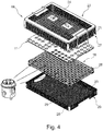
- the tool set 19 has the Fig. 4 the construction of a box with a bottom part 20, which is preferably designed as a holding device for receiving sleeves 1, a cover 22 having a handle 24 and a plurality of outer walls (frame). Furthermore, the tool set 19 has a closure 21 in the form of a resilient strap, which from the outside to the closed box can be pushed and lid 22 and bottom part 20 of the closed box engages around.
- the tool set 19 preferably includes an intermediate floor 16 as a (further) mounting device, can be used in the receiving sleeves 1 according to the invention as described below.
- an intermediate floor 16 as a (further) mounting device
- a printed template 11 can be placed on the intermediate floor 26 .
- the bottom part 20 of the tool set 19 has a grid 23 for attaching AIOS bearing elements.
- the outer walls, the lid 22, the bottom part 20 and the optional intermediate floor 16 of the tool set 19 are of light construction, i. H. made of a perforated material, here made of a metal grid or perforated plates.
- This has the advantage that cleaning fluids can easily penetrate into the tool set 19 and wash around the tools 14 accommodated in the receiving sleeves 1.
- the tool set 19 according to the invention does not have to be disassembled for cleaning or the tools 14 to be removed, but the entire tool set 19 can be cleaned in the assembled state without compromising the thoroughness of cleaning the tool set 19 or the tools 14 contained therein.
- the intermediate floor 16 preferably has at least one corner foot 25, which engages in at least one corresponding recess 26 in a projection on an outer wall of the bottom part 20 of the tool set 19 and so ensures an accurate placement of the intermediate floor 16 on the bottom part 20 of the tool set 19 and the intermediate floor 16 holds in position.
- the lid 22 also has at least one of its corners on a centering pin 27 which engages in a hole 28 in at least one corresponding corner of the intermediate floor 16, thus ensuring a snug fit placing the lid 22 on the box.
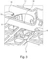
- the holding device for the receiving sleeves 1 in the form of the bottom part 20 and / or the intermediate floor 16 is according to the Fig. 3 formed from two parallel spaced perforated plates 17, 18, which are preferably interconnected. On the one perforated plate 17 are round holes and on the other perforated plate 18 are preferably rectangular Aussparrungen / holes except, wherein the holes of both perforated plates 17, 18 are arranged overlapping (co-axial), such that a receiving sleeve 1 in two superimposed holes of both perforated plates 17, 18 can be inserted.
- FIG. 1a shows in perspective view in the direction of insertion of a tool 14, a receiving sleeve 1 according to the invention with a hollow body (or hollow cylinder) 2 of light construction (Filigranbauweise) with an axial tool receiving opening 3 at its first axial end into which surgical tools 14 can be inserted ,
- the receiving sleeve 1 is in this case made in one piece preferably by injection molding or rapid prototyping method (sintering method) made of plastic.
- the receiving sleeve 1 has three or more elastically deformable, axially extending clamping arms 4, which preferably form a funnel within the hollow cylinder 2 of the receiving sleeve 1, which narrows in the insertion direction of a male tool 14.
- the diameter of the radially limited by the clamping arms 4 cavity is widened and the clamping arms 4 are pressed in the radial direction to the outside. Due to the elastic tension of the clamping arms 4, the inserted tool 14 is clamped in the cavity of the hollow cylinder 2 between the clamping arms 4.
- the clamping arms 4 are preferably formed so that the contact surface 15 between clamping arms 4 and 14 recorded tool 14 is as low as possible (dot / line).
- the clamping arms hold the tool at a radial distance from the hollow body 2.
- the clamping arms 4 on the inside of the receiving sleeve 1 may not be formed integrally with the hollow body 2 of the receiving sleeve 1, but separately manufactured, for example, made of metal and embedded in the hollow body 2 of the receiving sleeve 1. Such manufacture of the clamping arms 4 has an advantageous effect on the life and robustness of the receiving sleeve 1.
- the receiving sleeve 1 on its inside three or more rigid guide arms / longitudinal ribs 5, which are seen within the hollow cylinder 2 of the receiving sleeve 1 in the circumferential direction between the clamping arms 4 and also form a funnel, which narrows in the direction of insertion of a male tool 14 ,
- the rigid guide arms / longitudinal ribs 5 insertion of a tool 14 is prevented with too large shaft diameter in the receiving sleeve 1, as the guide arms 5, in contrast to the clamping arms 4 are not elastically deformable and thus clearly define a maximum shaft diameter of an insertable tool 14.
- the receiving sleeve 1 can be inserted into the holding device consisting of the two matrices 17, 18 and firmly anchored therein, as in particular in the Fig. 3 is shown, the receiving sleeve 1 further comprises on its outer surface / lateral surface according to the Fig. 1a at least one elastically deformable retaining arm / retaining wedge 6. If the receiving sleeve 1, for example, in a round hole of a hole matrix 17 (see Fig. 3 ) of the retaining device described above, the retaining arm / retaining wedge 6 is pressed by the radial boundary of the hole in the radial direction of the hollow cylinder 2 inwards.
- the retaining arm / retaining wedge 6 engages behind the hole matrix 17 as soon as the receiving sleeve 1 reaches the axial position in the round hole of the one hole matrix 17.
- the receiving opening 3 facing the free end of the retaining arm / retaining wedge 6 is formed as a radially outwardly extending projection / claw, which lies flat behind the one hole matrix 17 axially.
- FIG. 1b shows viewed in perspective view opposite to the direction of insertion of a tool 14 viewed, the receiving sleeve 1 from FIG. 1a ,
- the guide arms / longitudinal ribs 5 form a collecting tray / end stop 7 in the hollow cylinder 2 of the receiving sleeve 1 in order to prevent too deep insertion of a tool 14 into the receiving sleeve 1.
- the guide arms 5 are at their axial ends relative to the tool insertion end connected by a cross bar, which represents the collecting tray / end stop 7.
- the receiving sleeve 1 preferably has at its opposite axial end opposite the insertion end three rigid positioning longitudinal pins 8, which hold the receiving sleeve 1 in position when it is inserted into a holding device according to the above description.
- the positioning pins 8 of the receiving sleeve 1 are square / triangular in cross-section, so that they form fit in the corners of the angular recesses of the other matrix 18 according to the Fig. 3 engage and prevent a displacement / rotation of the receiving sleeve 1 in the holding device.
- the receiving sleeve 1 also has at its insertion opening 3 opposite axial end at least one elastically deformable hook-shaped latching arm 9 which extends axially similar to the positioning pin 8 and is formed so that it positively, for example, in a corner of an angular recess of the other matrix 18 of Engage holding device and this matrix 18 can engage behind axially, as shown in the Fig. 3 is shown.
- a receiving sleeve 1 is inserted into a holding device according to the invention (bottom 20 or intermediate layer 28) with two matrices 17, 18 arranged in parallel, of which the first matrix has 17 round holes and the second matrix 18 arranged in parallel therewith has angular recesses with the round holes the first matrix 17 are aligned, the receiving sleeve 1 is pressed through a round hole of the first matrix 17 until the hollow cylinder 2 comes to rest on the second matrix 18, as in particular in the Fig. 3 is shown.
- the at least one elastically deformable latching arm 9 is pressed through the recess of the second matrix 18 with angular holes until the hook-shaped projection of the latching arm 9 snaps behind the second matrix 18 and thus prevents movement and falling out of the receiving sleeve 1 against the insertion direction.
- the receiving sleeve 1 determines the parallel distance between the first and second matrix 17, 18, since the first matrix 17 comes to rest on the hook-shaped projection of the retaining arm 6 and the second Matrix 18 is held by the hook-shaped projection of the latching arm 9 in position.
- the receiving sleeve 1 further has a circumferential annular projection or collar 10 along the circumference of the hollow cylinder 2 at its one axial end portion in the region of the insertion opening 3, which rests in the inserted state of the receiving sleeve 1 in the mounting device on the first matrix 17 and thereby the first matrix 17 clamps axially between itself and the radial projection of the retaining arm / retaining wedge 6 and thus the parallel distance between the first and second matrix 17, 18 according to the Fig. 3 fixed.
- a circumferential annular projection or collar 10 along the circumference of the hollow cylinder 2 at its one axial end portion in the region of the insertion opening 3, which rests in the inserted state of the receiving sleeve 1 in the mounting device on the first matrix 17 and thereby the first matrix 17 clamps axially between itself and the radial projection of the retaining arm / retaining wedge 6 and thus the parallel distance between the first and second matrix 17, 18 according to the Fig. 3 fixed.
- the circumferential projection 10 is flattened on its side facing the first end of the receiving sleeve 1, so that a printed template 11 can be placed on the flattened side of the annular projection 10 in a form-fitting manner. Furthermore, the circumferential annular projection 10 on its side facing the second end of the receiving sleeve 1 side recesses 13, whereby the contact surface 15 between the circumferential projection 10 and the first matrix 17 of the holding device is reduced and any dirt accumulating between receiving sleeve 1 and mounting device, can be washed away efficiently by cleaning fluid.
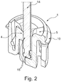
- FIG. 2 shows a cross section through a receiving sleeve 1 with a surgical tool 14 received therein.
- the tool 14 is therefore only at the defined contact points / - lines 15 in clamping contact with the clamping arms 4 and the collecting tray 7 of the receiving sleeve 1.
- the clamping arms 4 are preferably designed so that the contact points 15 between clamp arms 4 and 14 recorded tool as possible are small. Since the surface of the tool 14 bears frictionally only at the contact points 15 on the hollow body 2 of the receiving sleeve 1, is the Most of the surface of the received in the receiving sleeve 1 portion of the tool 14 is not in contact with the hollow body 2 of the receiving sleeve 1 and is thus um Hughesbar of cleaning fluid.
- FIG. 3 finally shows a receiving sleeve 1, which is inserted in the intermediate floor 16 or in the bottom 20 of the tool set 19 according to the invention.
- the intermediate floor 16 and / or the floor 20 consists of the two sheets arranged parallel to one another, one sheet having the stamped hole matrix 17 and the other sheet having the matrix 18 of angular recesses which are aligned with the circular holes of the matrix 17.
- the area of the angular recess of the matrix 18 is smaller than the area of the circular hole of the matrix 17.
- FIG. 3 It is clearly evident how the positioning pins 8 of the receiving sleeve 1 positively engage in each case in a corner of an angular recess of the matrix 18 and thus prevent rotation of the receiving sleeve 1 used.
- the latching arm 9 positively engages in a further corner of the angular recess of the matrix 18, wherein the hook-shaped projection of the latching arm 9 pushes under the sheet of the matrix 18 and thus anchored the receiving sleeve 1 in the intermediate floor 16 and in the bottom part 20.
- the radial projection of the retaining arm 6 pushes under the sheet of the matrix 17 and additionally serves to anchor the receiving sleeve 1 in the intermediate floor 16 or in the bottom 20th
- the distance between the two matrices 17 and 18 is, as already indicated, defined by the spacing between the projections of the latching arm 9 and the retention arm 6, on each of which the matrix 17 and the matrix 18 come to lie.
- the matrix 17 between the circumferential projection / collar 10 and the projection of the retaining arm 6 is held in position, while the matrix 18 is fixed between the hook-shaped projection of the latching arm 9 and the circumference of the hollow cylinder 2.
Landscapes
- Health & Medical Sciences (AREA)
- Life Sciences & Earth Sciences (AREA)
- Surgery (AREA)
- Veterinary Medicine (AREA)
- Public Health (AREA)
- Animal Behavior & Ethology (AREA)
- General Health & Medical Sciences (AREA)
- Heart & Thoracic Surgery (AREA)
- Nuclear Medicine, Radiotherapy & Molecular Imaging (AREA)
- Engineering & Computer Science (AREA)
- Biomedical Technology (AREA)
- Medical Informatics (AREA)
- Molecular Biology (AREA)
- Dentistry (AREA)
- Oral & Maxillofacial Surgery (AREA)
- Epidemiology (AREA)
- Dental Tools And Instruments Or Auxiliary Dental Instruments (AREA)
- Surgical Instruments (AREA)
Applications Claiming Priority (3)
| Application Number | Priority Date | Filing Date | Title |
|---|---|---|---|
| DE102014109197.3A DE102014109197A1 (de) | 2014-07-01 | 2014-07-01 | Lagerungssystem für medizinische Instrumente |
| PCT/EP2015/063576 WO2016000962A1 (fr) | 2014-07-01 | 2015-06-17 | Système de stockage d'instruments médicaux |
| EP15729480.2A EP3164095B1 (fr) | 2014-07-01 | 2015-06-17 | Système de stockage d'instruments médicaux |
Related Parent Applications (2)
| Application Number | Title | Priority Date | Filing Date |
|---|---|---|---|
| EP15729480.2A Division EP3164095B1 (fr) | 2014-07-01 | 2015-06-17 | Système de stockage d'instruments médicaux |
| EP15729480.2A Division-Into EP3164095B1 (fr) | 2014-07-01 | 2015-06-17 | Système de stockage d'instruments médicaux |
Publications (2)
| Publication Number | Publication Date |
|---|---|
| EP3466367A1 true EP3466367A1 (fr) | 2019-04-10 |
| EP3466367B1 EP3466367B1 (fr) | 2020-09-09 |
Family
ID=53404571
Family Applications (2)
| Application Number | Title | Priority Date | Filing Date |
|---|---|---|---|
| EP18204465.1A Active EP3466367B1 (fr) | 2014-07-01 | 2015-06-17 | Système de stockage pour instruments médicaux |
| EP15729480.2A Active EP3164095B1 (fr) | 2014-07-01 | 2015-06-17 | Système de stockage d'instruments médicaux |
Family Applications After (1)
| Application Number | Title | Priority Date | Filing Date |
|---|---|---|---|
| EP15729480.2A Active EP3164095B1 (fr) | 2014-07-01 | 2015-06-17 | Système de stockage d'instruments médicaux |
Country Status (7)
| Country | Link |
|---|---|
| US (2) | US10278790B2 (fr) |
| EP (2) | EP3466367B1 (fr) |
| JP (2) | JP6896429B2 (fr) |
| CN (2) | CN106535810B (fr) |
| DE (1) | DE102014109197A1 (fr) |
| ES (2) | ES2725459T3 (fr) |
| WO (1) | WO2016000962A1 (fr) |
Families Citing this family (13)
| Publication number | Priority date | Publication date | Assignee | Title |
|---|---|---|---|---|
| JP6863899B2 (ja) * | 2015-03-09 | 2021-04-21 | ストラウマン ホールディング アーゲー | 医療器具の保管のためのカセット |
| US11058507B2 (en) * | 2017-01-25 | 2021-07-13 | Edward STOLARSKI | Surgical draping holster system |
| JP7301265B2 (ja) | 2018-11-21 | 2023-07-03 | パナソニックエナジー株式会社 | 円筒体の搬送用保持具 |
| US10898244B2 (en) * | 2018-11-16 | 2021-01-26 | DePuy Synthes Products, Inc. | Packaging for trochanteric femoral nail telescoping head element |
| DE102021106109A1 (de) | 2021-03-12 | 2022-09-15 | Aesculap Ag | Aufnahme-Expanderhülse sowie Werkzeugset |
| DE102021106111A1 (de) | 2021-03-12 | 2022-09-15 | Aesculap Ag | Aufnahme-Expanderhülse sowie Werkzeugset |
| DE102021106110A1 (de) * | 2021-03-12 | 2022-09-15 | Aesculap Ag | Aufnahme-Expanderhülse sowie Werkzeugset |
| JP7478119B2 (ja) * | 2021-05-27 | 2024-05-02 | 富士フイルムヘルスケア株式会社 | プローブホルダ |
| EP4452122A4 (fr) * | 2021-12-22 | 2025-12-17 | Saban Ventures Pty Ltd | Dispositif de retenue d'un objet dans un appareil de stérilisation/désinfection |
| USD1073068S1 (en) | 2022-06-03 | 2025-04-29 | Saban Ventures Pty Limited | Accessory for holding a medical device |
| DE102023000231A1 (de) | 2023-01-27 | 2024-08-01 | Robert Simmoteit | Stift und Lagerungssystem |
| DE102023127412A1 (de) * | 2023-10-09 | 2025-04-10 | Aesculap Ag | Klemmvorrichtung und Werkzeugaufnahme |
| DE102024121708A1 (de) | 2024-07-30 | 2026-02-05 | Aesculap Ag | Aufnahme-Expanderhülse sowie Werkzeuglagerungsset |
Citations (2)
| Publication number | Priority date | Publication date | Assignee | Title |
|---|---|---|---|---|
| US20130046289A1 (en) * | 2011-08-17 | 2013-02-21 | Symmetry Medical Manufacturing, Inc. | Grommet Device with Flexible Bowed Members and Methods of Using Thereof |
| US20130064709A1 (en) * | 2011-09-14 | 2013-03-14 | Symmetry Medical Manufacturing, Inc. | Removable Grommet Device and Method of Using Thereof |
Family Cites Families (31)
| Publication number | Priority date | Publication date | Assignee | Title |
|---|---|---|---|---|
| DE1275438B (de) * | 1966-02-25 | 1968-08-14 | Karlsruhe Augsburg Iweka | Selbstzentrierender Halter fuer Tuben an einer Tubenfuell- und -schliessmaschine |
| US4798292A (en) * | 1987-04-03 | 1989-01-17 | Biomedical Laser Industries | Sterilization, storage, and presentation container for surgical instruments |
| US4919264A (en) * | 1988-08-04 | 1990-04-24 | Shinall Kimberly A | Medical needle removing and disposing system |
| DE69308493T2 (de) * | 1992-06-29 | 1997-10-23 | Dade Int Inc | Träger für proberöhrchen |
| US5533700A (en) * | 1995-02-16 | 1996-07-09 | Porter; Dennis | Holder for a container |
| SE9500777D0 (sv) * | 1995-03-03 | 1995-03-03 | Pharmacia Ab | Provrörshållarinsats |
| US5941366A (en) * | 1996-09-19 | 1999-08-24 | Labotix Automation, Inc. | Transport system for biospecimens |
| US5918740A (en) | 1997-05-05 | 1999-07-06 | Carr Metal Products, Inc. | Instrument cassette |
| US5897090A (en) * | 1997-11-13 | 1999-04-27 | Bayer Corporation | Puck for a sample tube |
| US6176369B1 (en) * | 1998-10-08 | 2001-01-23 | Gebo Conveyors, Consultants & Systems, Inc. | Steerable carrier puck |
| JP3096685B2 (ja) * | 1999-03-05 | 2000-10-10 | 照明 伊藤 | 試験管ホルダー |
| DE19916025A1 (de) * | 1999-04-09 | 2000-10-12 | Kaltenbach & Voigt | Vorrichtung zur Aufnahme von länglichen Werkzeugen in einer bestimmten Aufnahmeposition, insbesondere zur Aufnahme von Wurzelkanalfeilen |
| US6343690B1 (en) * | 1999-10-18 | 2002-02-05 | Coulter International Corp. | Specimen carrier for automated transport system and method and apparatus for identifying same |
| US6494822B1 (en) * | 2000-09-01 | 2002-12-17 | Unova Ip Corp | Tool retention mechanism |
| FI114661B (fi) * | 2001-04-03 | 2004-11-30 | Thermo Clinical Labsystems Oy | Koeputkialusta |
| JP3721341B2 (ja) * | 2002-05-14 | 2005-11-30 | 株式会社アイディエス | 試験管保持用アダプター |
| US7066329B2 (en) * | 2003-07-21 | 2006-06-27 | Riley Medical, Inc. | Medical instrument holding and presentation system |
| US20050161355A1 (en) * | 2003-11-26 | 2005-07-28 | Hu-Friedy Mfg. Co., Inc. | Configurable cassettes |
| JP4056982B2 (ja) * | 2004-03-17 | 2008-03-05 | 株式会社アイディエス | 試験管ホルダー |
| US7232038B2 (en) * | 2004-04-27 | 2007-06-19 | Whitney Steven G | Disposable test tube rack |
| US7910067B2 (en) * | 2005-04-19 | 2011-03-22 | Gen-Probe Incorporated | Sample tube holder |
| DE102007015154A1 (de) * | 2007-03-22 | 2008-09-25 | Aesculap Ag & Co. Kg | Haltevorrichtung für ein Implantat |
| DE202007016144U1 (de) * | 2007-11-16 | 2008-02-14 | Busch & Co. Kg | Bohrerständer |
| DE202009002639U1 (de) * | 2009-02-26 | 2009-05-07 | Medartis Ag | Träger und Halterung für chirurgische Gegenstände |
| US20120138495A1 (en) * | 2009-11-09 | 2012-06-07 | Bettenhausen Cary A | Universal surgical fastener sterilization caddy |
| CN201701325U (zh) * | 2010-04-14 | 2011-01-12 | 鑫锐兴业有限公司 | 多功能牙针包装盒 |
| US8936151B2 (en) * | 2010-04-17 | 2015-01-20 | Michael Abene | Dental instrument securing system |
| PT2502675E (pt) * | 2011-03-25 | 2014-04-23 | Symbion Medical Systems S Rl | Suporte de recipiente e porta-recipiente |
| EP2698123B1 (fr) * | 2012-08-15 | 2016-10-05 | Dentsply IH AB | Système de plateau et procédé de préparation d'une feuille d'informations personnalisée |
| US20140171801A1 (en) | 2012-12-19 | 2014-06-19 | General Electric Company | Medical device support apparatus |
| EP2759277B1 (fr) * | 2013-01-23 | 2020-05-27 | Symmetry Medical Manufacturing, Inc. | Plateau de dispositif médical et procédé de formation du plateau de dispositif médical |
-
2014
- 2014-07-01 DE DE102014109197.3A patent/DE102014109197A1/de not_active Withdrawn
-
2015
- 2015-06-17 JP JP2016575365A patent/JP6896429B2/ja active Active
- 2015-06-17 ES ES15729480T patent/ES2725459T3/es active Active
- 2015-06-17 EP EP18204465.1A patent/EP3466367B1/fr active Active
- 2015-06-17 WO PCT/EP2015/063576 patent/WO2016000962A1/fr not_active Ceased
- 2015-06-17 CN CN201580036147.9A patent/CN106535810B/zh active Active
- 2015-06-17 EP EP15729480.2A patent/EP3164095B1/fr active Active
- 2015-06-17 US US15/322,254 patent/US10278790B2/en active Active
- 2015-06-17 ES ES18204465T patent/ES2834337T3/es active Active
- 2015-06-17 CN CN201911261438.4A patent/CN111202588B/zh active Active
-
2019
- 2019-03-29 US US16/369,256 patent/US11278373B2/en active Active
-
2021
- 2021-06-09 JP JP2021096884A patent/JP7360421B2/ja active Active
Patent Citations (2)
| Publication number | Priority date | Publication date | Assignee | Title |
|---|---|---|---|---|
| US20130046289A1 (en) * | 2011-08-17 | 2013-02-21 | Symmetry Medical Manufacturing, Inc. | Grommet Device with Flexible Bowed Members and Methods of Using Thereof |
| US20130064709A1 (en) * | 2011-09-14 | 2013-03-14 | Symmetry Medical Manufacturing, Inc. | Removable Grommet Device and Method of Using Thereof |
Also Published As
| Publication number | Publication date |
|---|---|
| JP6896429B2 (ja) | 2021-06-30 |
| CN111202588B (zh) | 2023-05-09 |
| EP3164095A1 (fr) | 2017-05-10 |
| DE102014109197A1 (de) | 2016-01-07 |
| JP2021154139A (ja) | 2021-10-07 |
| CN111202588A (zh) | 2020-05-29 |
| US10278790B2 (en) | 2019-05-07 |
| ES2725459T3 (es) | 2019-09-24 |
| JP7360421B2 (ja) | 2023-10-12 |
| EP3466367B1 (fr) | 2020-09-09 |
| ES2834337T3 (es) | 2021-06-17 |
| US20170143449A1 (en) | 2017-05-25 |
| JP2017522957A (ja) | 2017-08-17 |
| EP3164095B1 (fr) | 2019-03-13 |
| CN106535810B (zh) | 2019-12-10 |
| US11278373B2 (en) | 2022-03-22 |
| CN106535810A (zh) | 2017-03-22 |
| US20190223981A1 (en) | 2019-07-25 |
| WO2016000962A1 (fr) | 2016-01-07 |
Similar Documents
| Publication | Publication Date | Title |
|---|---|---|
| EP3164095B1 (fr) | Système de stockage d'instruments médicaux | |
| EP2027829B1 (fr) | Glissière de foret pourvue d'une butée | |
| DE2740335A1 (de) | Wegwerfbehaelter fuer einmalkanuelen | |
| DE202004004844U1 (de) | Schraubendreher für Knochenschrauben | |
| DE102010017624A1 (de) | Haltevorrichtung zum Reinigen und Lagern chirurgischer Handstücke und Siebkorb mit einer solchen Halterung | |
| DE60309639T2 (de) | Anzugsanker für eine zahnärztliche magnetische Haltevorrichtung | |
| EP4110224B1 (fr) | Douille expansible de réception et jeu d'instruments | |
| EP4110223B1 (fr) | Manchon de support extensible et ensemble d'outils | |
| EP4304513B1 (fr) | Manchon de support expansible et ensemble d'instruments | |
| DE3201800A1 (de) | Griff fuer rotierende zahnaertzliche wurzelkanalbehandlungsinstrumente | |
| EP1827282B1 (fr) | Element auxiliaire pour le reglage longitudinal d'implants de l'oreille moyenne | |
| DE202019005200U1 (de) | Behälter zum Reinigen von chirurgischen Instrumenten | |
| DE102021122276A1 (de) | Aufnahmeanordnung zur Aufnahme von chirurgischen Instrumenten mit werkzeugspezifischer Instrumentenaufnahme und betreffendes Herstellungsverfahren | |
| DE102014106373A1 (de) | Fräswerkzeug für prothetische chirurgische eingriffe | |
| EP0818296B1 (fr) | Objet moulé par injection et dispositif pour sa fabrication | |
| DE102021107077B4 (de) | Bohrer für den Alveolarknochen | |
| DE102024121708A1 (de) | Aufnahme-Expanderhülse sowie Werkzeuglagerungsset | |
| DE102023000231A1 (de) | Stift und Lagerungssystem | |
| DE202016008465U1 (de) | Spülkorb zum Aufnehmen von mehreren Behältern und Verwendung eines solchen Spülkorbes | |
| DE102023130810B3 (de) | Verbissschutzvorrichtung für Terminaltriebe von Bäumen | |
| DE19916025A1 (de) | Vorrichtung zur Aufnahme von länglichen Werkzeugen in einer bestimmten Aufnahmeposition, insbesondere zur Aufnahme von Wurzelkanalfeilen | |
| DE202019101306U1 (de) | Bohrhülsen-Führungshülsenanordnung für chirurgische Bohrinstrumente | |
| DE102024105951A1 (de) | Medizinische Aufbereitungsvorrichtung mit zylinderförmiger Filterkartusche | |
| EP4475562A1 (fr) | Ensemble de maintenance de prothèse auditive | |
| DE10326183A1 (de) | Vorrichtungen und Verfahren zur Gewinnung, Wiedergewinnung und Präparation von Abstrich-Zellmaterial |
Legal Events
| Date | Code | Title | Description |
|---|---|---|---|
| PUAI | Public reference made under article 153(3) epc to a published international application that has entered the european phase |
Free format text: ORIGINAL CODE: 0009012 |
|
| STAA | Information on the status of an ep patent application or granted ep patent |
Free format text: STATUS: THE APPLICATION HAS BEEN PUBLISHED |
|
| AC | Divisional application: reference to earlier application |
Ref document number: 3164095 Country of ref document: EP Kind code of ref document: P |
|
| AK | Designated contracting states |
Kind code of ref document: A1 Designated state(s): AL AT BE BG CH CY CZ DE DK EE ES FI FR GB GR HR HU IE IS IT LI LT LU LV MC MK MT NL NO PL PT RO RS SE SI SK SM TR |
|
| STAA | Information on the status of an ep patent application or granted ep patent |
Free format text: STATUS: REQUEST FOR EXAMINATION WAS MADE |
|
| 17P | Request for examination filed |
Effective date: 20191010 |
|
| RBV | Designated contracting states (corrected) |
Designated state(s): AL AT BE BG CH CY CZ DE DK EE ES FI FR GB GR HR HU IE IS IT LI LT LU LV MC MK MT NL NO PL PT RO RS SE SI SK SM TR |
|
| RIC1 | Information provided on ipc code assigned before grant |
Ipc: A61B 50/30 20160101ALN20200220BHEP Ipc: A61C 19/02 20060101ALI20200220BHEP Ipc: A61B 50/00 20160101ALN20200220BHEP Ipc: A61C 3/04 20060101AFI20200220BHEP Ipc: A61B 50/20 20160101ALN20200220BHEP Ipc: A61B 50/34 20160101ALN20200220BHEP |
|
| GRAP | Despatch of communication of intention to grant a patent |
Free format text: ORIGINAL CODE: EPIDOSNIGR1 |
|
| STAA | Information on the status of an ep patent application or granted ep patent |
Free format text: STATUS: GRANT OF PATENT IS INTENDED |
|
| INTG | Intention to grant announced |
Effective date: 20200330 |
|
| GRAS | Grant fee paid |
Free format text: ORIGINAL CODE: EPIDOSNIGR3 |
|
| GRAA | (expected) grant |
Free format text: ORIGINAL CODE: 0009210 |
|
| STAA | Information on the status of an ep patent application or granted ep patent |
Free format text: STATUS: THE PATENT HAS BEEN GRANTED |
|
| AC | Divisional application: reference to earlier application |
Ref document number: 3164095 Country of ref document: EP Kind code of ref document: P |
|
| AK | Designated contracting states |
Kind code of ref document: B1 Designated state(s): AL AT BE BG CH CY CZ DE DK EE ES FI FR GB GR HR HU IE IS IT LI LT LU LV MC MK MT NL NO PL PT RO RS SE SI SK SM TR |
|
| REG | Reference to a national code |
Ref country code: GB Ref legal event code: FG4D Free format text: NOT ENGLISH |
|
| REG | Reference to a national code |
Ref country code: AT Ref legal event code: REF Ref document number: 1310602 Country of ref document: AT Kind code of ref document: T Effective date: 20200915 Ref country code: CH Ref legal event code: EP |
|
| REG | Reference to a national code |
Ref country code: DE Ref legal event code: R096 Ref document number: 502015013442 Country of ref document: DE |
|
| REG | Reference to a national code |
Ref country code: IE Ref legal event code: FG4D Free format text: LANGUAGE OF EP DOCUMENT: GERMAN |
|
| REG | Reference to a national code |
Ref country code: LT Ref legal event code: MG4D |
|
| PG25 | Lapsed in a contracting state [announced via postgrant information from national office to epo] |
Ref country code: GR Free format text: LAPSE BECAUSE OF FAILURE TO SUBMIT A TRANSLATION OF THE DESCRIPTION OR TO PAY THE FEE WITHIN THE PRESCRIBED TIME-LIMIT Effective date: 20201210 Ref country code: LT Free format text: LAPSE BECAUSE OF FAILURE TO SUBMIT A TRANSLATION OF THE DESCRIPTION OR TO PAY THE FEE WITHIN THE PRESCRIBED TIME-LIMIT Effective date: 20200909 Ref country code: FI Free format text: LAPSE BECAUSE OF FAILURE TO SUBMIT A TRANSLATION OF THE DESCRIPTION OR TO PAY THE FEE WITHIN THE PRESCRIBED TIME-LIMIT Effective date: 20200909 Ref country code: SE Free format text: LAPSE BECAUSE OF FAILURE TO SUBMIT A TRANSLATION OF THE DESCRIPTION OR TO PAY THE FEE WITHIN THE PRESCRIBED TIME-LIMIT Effective date: 20200909 Ref country code: HR Free format text: LAPSE BECAUSE OF FAILURE TO SUBMIT A TRANSLATION OF THE DESCRIPTION OR TO PAY THE FEE WITHIN THE PRESCRIBED TIME-LIMIT Effective date: 20200909 Ref country code: NO Free format text: LAPSE BECAUSE OF FAILURE TO SUBMIT A TRANSLATION OF THE DESCRIPTION OR TO PAY THE FEE WITHIN THE PRESCRIBED TIME-LIMIT Effective date: 20201209 Ref country code: BG Free format text: LAPSE BECAUSE OF FAILURE TO SUBMIT A TRANSLATION OF THE DESCRIPTION OR TO PAY THE FEE WITHIN THE PRESCRIBED TIME-LIMIT Effective date: 20201209 |
|
| REG | Reference to a national code |
Ref country code: NL Ref legal event code: MP Effective date: 20200909 |
|
| PG25 | Lapsed in a contracting state [announced via postgrant information from national office to epo] |
Ref country code: RS Free format text: LAPSE BECAUSE OF FAILURE TO SUBMIT A TRANSLATION OF THE DESCRIPTION OR TO PAY THE FEE WITHIN THE PRESCRIBED TIME-LIMIT Effective date: 20200909 Ref country code: PL Free format text: LAPSE BECAUSE OF FAILURE TO SUBMIT A TRANSLATION OF THE DESCRIPTION OR TO PAY THE FEE WITHIN THE PRESCRIBED TIME-LIMIT Effective date: 20200909 Ref country code: LV Free format text: LAPSE BECAUSE OF FAILURE TO SUBMIT A TRANSLATION OF THE DESCRIPTION OR TO PAY THE FEE WITHIN THE PRESCRIBED TIME-LIMIT Effective date: 20200909 |
|
| PG25 | Lapsed in a contracting state [announced via postgrant information from national office to epo] |
Ref country code: SM Free format text: LAPSE BECAUSE OF FAILURE TO SUBMIT A TRANSLATION OF THE DESCRIPTION OR TO PAY THE FEE WITHIN THE PRESCRIBED TIME-LIMIT Effective date: 20200909 Ref country code: CZ Free format text: LAPSE BECAUSE OF FAILURE TO SUBMIT A TRANSLATION OF THE DESCRIPTION OR TO PAY THE FEE WITHIN THE PRESCRIBED TIME-LIMIT Effective date: 20200909 Ref country code: PT Free format text: LAPSE BECAUSE OF FAILURE TO SUBMIT A TRANSLATION OF THE DESCRIPTION OR TO PAY THE FEE WITHIN THE PRESCRIBED TIME-LIMIT Effective date: 20210111 Ref country code: RO Free format text: LAPSE BECAUSE OF FAILURE TO SUBMIT A TRANSLATION OF THE DESCRIPTION OR TO PAY THE FEE WITHIN THE PRESCRIBED TIME-LIMIT Effective date: 20200909 Ref country code: EE Free format text: LAPSE BECAUSE OF FAILURE TO SUBMIT A TRANSLATION OF THE DESCRIPTION OR TO PAY THE FEE WITHIN THE PRESCRIBED TIME-LIMIT Effective date: 20200909 |
|
| PG25 | Lapsed in a contracting state [announced via postgrant information from national office to epo] |
Ref country code: AL Free format text: LAPSE BECAUSE OF FAILURE TO SUBMIT A TRANSLATION OF THE DESCRIPTION OR TO PAY THE FEE WITHIN THE PRESCRIBED TIME-LIMIT Effective date: 20200909 Ref country code: IS Free format text: LAPSE BECAUSE OF FAILURE TO SUBMIT A TRANSLATION OF THE DESCRIPTION OR TO PAY THE FEE WITHIN THE PRESCRIBED TIME-LIMIT Effective date: 20210109 |
|
| REG | Reference to a national code |
Ref country code: DE Ref legal event code: R097 Ref document number: 502015013442 Country of ref document: DE |
|
| REG | Reference to a national code |
Ref country code: ES Ref legal event code: FG2A Ref document number: 2834337 Country of ref document: ES Kind code of ref document: T3 Effective date: 20210617 |
|
| PG25 | Lapsed in a contracting state [announced via postgrant information from national office to epo] |
Ref country code: SK Free format text: LAPSE BECAUSE OF FAILURE TO SUBMIT A TRANSLATION OF THE DESCRIPTION OR TO PAY THE FEE WITHIN THE PRESCRIBED TIME-LIMIT Effective date: 20200909 |
|
| PLBE | No opposition filed within time limit |
Free format text: ORIGINAL CODE: 0009261 |
|
| STAA | Information on the status of an ep patent application or granted ep patent |
Free format text: STATUS: NO OPPOSITION FILED WITHIN TIME LIMIT |
|
| 26N | No opposition filed |
Effective date: 20210610 |
|
| PG25 | Lapsed in a contracting state [announced via postgrant information from national office to epo] |
Ref country code: SI Free format text: LAPSE BECAUSE OF FAILURE TO SUBMIT A TRANSLATION OF THE DESCRIPTION OR TO PAY THE FEE WITHIN THE PRESCRIBED TIME-LIMIT Effective date: 20200909 Ref country code: DK Free format text: LAPSE BECAUSE OF FAILURE TO SUBMIT A TRANSLATION OF THE DESCRIPTION OR TO PAY THE FEE WITHIN THE PRESCRIBED TIME-LIMIT Effective date: 20200909 |
|
| PG25 | Lapsed in a contracting state [announced via postgrant information from national office to epo] |
Ref country code: MC Free format text: LAPSE BECAUSE OF FAILURE TO SUBMIT A TRANSLATION OF THE DESCRIPTION OR TO PAY THE FEE WITHIN THE PRESCRIBED TIME-LIMIT Effective date: 20200909 |
|
| REG | Reference to a national code |
Ref country code: CH Ref legal event code: PL |
|
| REG | Reference to a national code |
Ref country code: BE Ref legal event code: MM Effective date: 20210630 |
|
| PG25 | Lapsed in a contracting state [announced via postgrant information from national office to epo] |
Ref country code: LU Free format text: LAPSE BECAUSE OF NON-PAYMENT OF DUE FEES Effective date: 20210617 |
|
| PG25 | Lapsed in a contracting state [announced via postgrant information from national office to epo] |
Ref country code: LI Free format text: LAPSE BECAUSE OF NON-PAYMENT OF DUE FEES Effective date: 20210630 Ref country code: IE Free format text: LAPSE BECAUSE OF NON-PAYMENT OF DUE FEES Effective date: 20210617 Ref country code: CH Free format text: LAPSE BECAUSE OF NON-PAYMENT OF DUE FEES Effective date: 20210630 |
|
| PG25 | Lapsed in a contracting state [announced via postgrant information from national office to epo] |
Ref country code: BE Free format text: LAPSE BECAUSE OF NON-PAYMENT OF DUE FEES Effective date: 20210630 |
|
| REG | Reference to a national code |
Ref country code: AT Ref legal event code: MM01 Ref document number: 1310602 Country of ref document: AT Kind code of ref document: T Effective date: 20210617 |
|
| PG25 | Lapsed in a contracting state [announced via postgrant information from national office to epo] |
Ref country code: AT Free format text: LAPSE BECAUSE OF NON-PAYMENT OF DUE FEES Effective date: 20210617 |
|
| PG25 | Lapsed in a contracting state [announced via postgrant information from national office to epo] |
Ref country code: NL Free format text: LAPSE BECAUSE OF NON-PAYMENT OF DUE FEES Effective date: 20200923 Ref country code: CY Free format text: LAPSE BECAUSE OF FAILURE TO SUBMIT A TRANSLATION OF THE DESCRIPTION OR TO PAY THE FEE WITHIN THE PRESCRIBED TIME-LIMIT Effective date: 20200909 |
|
| PG25 | Lapsed in a contracting state [announced via postgrant information from national office to epo] |
Ref country code: HU Free format text: LAPSE BECAUSE OF FAILURE TO SUBMIT A TRANSLATION OF THE DESCRIPTION OR TO PAY THE FEE WITHIN THE PRESCRIBED TIME-LIMIT; INVALID AB INITIO Effective date: 20150617 |
|
| PG25 | Lapsed in a contracting state [announced via postgrant information from national office to epo] |
Ref country code: MK Free format text: LAPSE BECAUSE OF FAILURE TO SUBMIT A TRANSLATION OF THE DESCRIPTION OR TO PAY THE FEE WITHIN THE PRESCRIBED TIME-LIMIT Effective date: 20200909 |
|
| PG25 | Lapsed in a contracting state [announced via postgrant information from national office to epo] |
Ref country code: TR Free format text: LAPSE BECAUSE OF FAILURE TO SUBMIT A TRANSLATION OF THE DESCRIPTION OR TO PAY THE FEE WITHIN THE PRESCRIBED TIME-LIMIT Effective date: 20200909 |
|
| PG25 | Lapsed in a contracting state [announced via postgrant information from national office to epo] |
Ref country code: MT Free format text: LAPSE BECAUSE OF FAILURE TO SUBMIT A TRANSLATION OF THE DESCRIPTION OR TO PAY THE FEE WITHIN THE PRESCRIBED TIME-LIMIT Effective date: 20200909 |
|
| PGFP | Annual fee paid to national office [announced via postgrant information from national office to epo] |
Ref country code: DE Payment date: 20250618 Year of fee payment: 11 |
|
| PGFP | Annual fee paid to national office [announced via postgrant information from national office to epo] |
Ref country code: GB Payment date: 20250620 Year of fee payment: 11 |
|
| PGFP | Annual fee paid to national office [announced via postgrant information from national office to epo] |
Ref country code: FR Payment date: 20250618 Year of fee payment: 11 |
|
| PGFP | Annual fee paid to national office [announced via postgrant information from national office to epo] |
Ref country code: ES Payment date: 20250718 Year of fee payment: 11 |
|
| PGFP | Annual fee paid to national office [announced via postgrant information from national office to epo] |
Ref country code: IT Payment date: 20250630 Year of fee payment: 11 |