EP3466714A1 - Halbzeug für die herstellung von heftstreifen - Google Patents
Halbzeug für die herstellung von heftstreifen Download PDFInfo
- Publication number
- EP3466714A1 EP3466714A1 EP18196710.0A EP18196710A EP3466714A1 EP 3466714 A1 EP3466714 A1 EP 3466714A1 EP 18196710 A EP18196710 A EP 18196710A EP 3466714 A1 EP3466714 A1 EP 3466714A1
- Authority
- EP
- European Patent Office
- Prior art keywords
- strip
- tape
- stitching
- unwinding
- holes
- Prior art date
- Legal status (The legal status is an assumption and is not a legal conclusion. Google has not performed a legal analysis and makes no representation as to the accuracy of the status listed.)
- Granted
Links
Images
Classifications
-
- B—PERFORMING OPERATIONS; TRANSPORTING
- B42—BOOKBINDING; ALBUMS; FILES; SPECIAL PRINTED MATTER
- B42F—SHEETS TEMPORARILY ATTACHED TOGETHER; FILING APPLIANCES; FILE CARDS; INDEXING
- B42F11/00—Filing appliances with separate intermediate holding means
Definitions
- the present invention relates to a semi-finished, more precisely a Abrollband for singling in stitching strips, the at least two Abheftlöcher and / or a centrally disposed slot along the direction for performing a band, equidistant perforations for engaging a spiked roller and a label for authentication and determination of the type and Quality of Abrollbandes and the length of the separated adhesive strips by a sensor include.
- the unwinding belt is designed such that it can be detected automatically by a device for applying adhesive strip from a rolling strip on sheet material, by means of a sensor on the guide means and fed via a spiked roller acting as a feed device and the HeftstMail by a equipped with a cutting device An horrbalken without waste Sheet material can be applied.
- a striping machine automatically sticks from below stapling strips against unfolded sheets or the last layer of folded sheets. This way, documents, drawings, layouts of different formats can be uniformly provided with adhesive strips and secure against tearing. By using adhesive strips with Abheftlöchern the sheets can be filed without a cumbersome diagonal fold introduced or the sheets must be subsequently punched.
- sheets, in particular official documents can be sealed or sealed by means of stitching strips with a closed slot over a banderole which is passed through the slots.
- WO 2004/039605 A2 discloses a tacking tape dispenser for the application of tacking tabs on sheets which is capable of applying various types of holes, such as double or quadruple punching, to sheets.
- the transport of the HeftstMailbandes is applied to the applicator via a sprocket provided as a feed device whose prong-shaped pin engage in transport holes of the HeftstMailbandes realized.
- the spiked roller is rotated by a predetermined angle so that the stitching strip is fed to the applicator and onto the sheet can be applied.
- a different number of holes on the stitching strip can only be achieved with a special tape strip in which the holes comply with standard distances between the adjoining sections. Different types of tape, such as European or Scandinavian standard, can not be processed with this tape dispenser.
- the international patent application WO 2015/135653 A1 discloses a HeftstMailautomaten for applying HeftstMail on sheet goods, in which the transport of the HeftstMailbandes on the winding of the adhesive film covering masking tape takes place.
- the cover strip is separated by a deflection of the HeftstMailband and wound on a roll, while being guided by the winding of the cover strip of the HeftstMail on a An horrbalken.
- the stitching tape is conveyed in this embodiment in the running direction by the cover strip is moved over a pulley against the direction of the stitching tape and wound.
- the An horrinken is equipped with an optical sensor that detects the Abheftlöcher the tape tab, and so different types of Heftstreiftenpen can be automatically detected and processed by a control unit.
- the masking tape is not very tear-resistant, since it really only has the task to cover the adhesive film and not be responsible by train for unwinding and conveying the entire tape strip. Therefore, if the cover strip tears, the entire device stops, has to be opened manually and the tape has to be re-threaded manually.
- this type of drive is clearly inferior to a spiked roller, since on the one hand the cover band has a certain elasticity, which makes the precise advancement of the adhesive tape harder.
- the masking tape is due to its task to cover the adhesive film so that when removing the masking tape no adhesive remains, but the adhesive remains entirely on the HeftstMailband provided with a slightly lubricious surface, causing the masking tape very poorly wound on itself leaves. Even if the winding of the cover strip runs without errors, the diameter of the winding increases as the number of windings of the wound cover tape increases, so that the cover strip is wound up faster and faster with the drive speed remaining constant, thus carrying the tape strip faster and faster, which results in accurate positioning of the strip tape makes it difficult.
- the tape strip can not be processed lossless.
- a length of multiple Heftstsammlungabitesen is on overlapping masking tape required when inserting the HeftstMailbandes in the HeftstMailautomaten so that the cover strip can be rolled up.
- the corresponding adhesive strips are not available for application to the sheet and must be manually separated and removed by the user of the HeftstMailautomatens.
- the manual separation of the protruding tape strips poses a certain security risk and a certain effort for the user, since he must remove the tape with clean adhesive tape clean and straight within the HeftstMailautomatens and without the adhesive film inadvertently to bring with a component of the device in contact, remove ,
- the position and type of the tape is determined from the filing holes only when a complete tape portion has passed the sensor on the pressure bar.
- This tape strip portion can also no longer be applied to the sheets and must be disposed of manually by the user as waste.
- a tacking tape can not be used without waste in such a HeftstMailautomaten and the effort of threading the HeftstMailbandes to the point that the HeftstMailautomat is ready for use is still relatively high and complicated and thus operator unfriendly.
- a stapling hole strip for filing documents in a ring binder the strip being provided with holes in each of which a slot ends and the transparent edge of which is provided with rubber for adhering documents, is disclosed in the patent FR 633 478 A described.
- a half-means consisting of a band-shaped carrier film, on which a plurality of removable tacking strips is applied transversely to the tape direction, is disclosed in the European patent application EP 0 864 442 A1 described.
- the stitching strips have an adhesive part for attachment to sheets and a non-adhesive area with filing holes.
- the stitching strips are detached by means of a device over an edge of the carrier film and glued to a sheet.
- the object of the present invention is therefore to provide a half-weight in the form of a Abrollbandes for separating stitching strips, which is designed such that the Abrollband inserted without waste and as easy as possible in a device for applying adhesive tape on sheets, automatically detected, authenticated and retracted can.
- the stitching strips of the Abrollbandes to be separated should also be suitable for various filing formats and as universally applicable for a recognized by the associated device and also allow instead of or in addition to the filing the binding by means of banderole.
- the unwinding strip according to the invention for singling into stitching strips consists of a stitching strip tape with picking holes and / or slots along the running direction, and with equidistant perforations along the running direction for engaging a spiked roller, a continuous adhesive film covering the binding strip on one side, a protective tape covering the adhesive film and along the Running direction identical markings are provided with a predetermined distance to determine the nature and quality of the Abrollbandes and the length of the individual stitching strips by a sensor.
- the Abrollband can be separated by means of a device stapling strips and applied to sheets, the device comprises a take-off roll, equipped with a sensor for detecting the mark guide means, acting as a feed device spiked roller with drive, an applicator with drive and a control unit for controlling the Spiked roller drive and the applicator drive for automatically loading and positioning the tacking tape in accordance with the identifications detected by the sensor.
- the transport of the perforated adhesive tape by means of a spiked roller has significant advantages in terms of the precision of the transport of the adhesive tape and very low susceptibility and has therefore been very successful. Moreover, over is a spiked roller drive also in principle the carriage in both directions, ie in the unwinding and in the winding direction of the tape strip Heft possible, whereby a very precise positioning of the HeftstMailbandes can be done.
- the inventive Abrollband is equipped with markings with or at a predetermined distance along the direction, which are detected by the sensor of the device.
- the sensor is connected via a control unit with the drive of the spiked roller and the drive of the applicator, so that the advancement of the adhesive tape and the application of the tacking strip on sheet material takes place automatically and without intervention of the user.
- the markings in the Abrollband have three functions.
- the type of HeftstMailbandes is recognized by the markings such.
- an authentication of the Abrollbandes to determine whether it is a suitable for the device for cutting and attaching the separated stitching strips Abrollband is or a plagiarism, which could lead to malfunction in use or even damage the device.
- markings of the Abrollbandes are designed so that they can be detected by a sensor, preferably an optical sensor.
- a warning signal is preferably displayed or output by the device, or the device stops until an authenticated unwinding belt has been inserted, in order to prevent malfunctions and even damage to the device.
- This guide means is also immobile, so that the sensor is attached to an immovable part of the device, resulting in a very low susceptibility and high accuracy of the measurement of the sensor.
- the feed through the spiked roller is controlled according to the type of stitching tape detected, so that different types of tape with different lengths and holes or slots such as slots and slots, such as a European 2-hole tape with 111 mm Length or a Scandinavian 2-hole adhesive strip with 134 mm length as well as a French adhesive strip with slot for a band can be processed by the device according to the invention.
- different types of tape with different lengths and holes or slots such as slots and slots, such as a European 2-hole tape with 111 mm Length or a Scandinavian 2-hole adhesive strip with 134 mm length as well as a French adhesive strip with slot for a band can be processed by the device according to the invention.
- the type and position of the tape tab tape according to the invention are determined by the sensor of the device before the tape tab strip is fed to the applicator.
- the tape strip is automatically guided on the applicator and placed in the correct position for application to the sheet. This is possible only because the sensor is located on a guide means at least one tack strip length away from the applicator and not on the applicator itself, which e.g. could be a stamp.
- the senor already detects when inserting an unwinding, whether it is authentic or it is a plagiarized inferior quality, which can lead to disturbances or even damage to the device for applying the adhesive strips. Accordingly, the device warns the user by an appropriate indication that the loaded unwinding belt may cause malfunction when operated, or the device will stop functioning altogether until the unwinding belt has been replaced with an authenticated unwinding belt. This authentication takes place via the additional markings, which are not identical with the perforation and also with the perforation.
- the perforation for engaging the prongs of a spiked roller the perforation for engaging the prongs of a spiked roller
- the marking which the position of the tape strip for loss-free separation the type of tape strip such as European, Scandinavian or French type and for authentication the Abrollbandes and possibly generating a corresponding warning or stopping the device is used.
- the perforation is thus different and not identical to the markings and the markings are different and not identical to the picking holes and / or slots and the picking holes and / or slots are different and not identical to the perforation.
- engaging a spiked roller (7) refers to the engagement of the spikes of a spiked roller (7).
- the present invention thus relates to a Abrollband (3) for singling in the adhesive strip (17), the at least two Abheftlöcher and / or a centrally disposed slot along the direction for performing a band, equidistant perforations (19) for engaging a spiked roller (7) and a marking (20) for authentication and determination of the type and quality of the Abrollbandes (3) and the length of the separated adhesive strips (17) by a sensor
- the unwinding belt (3) comprises a stitching tape (4) with picking holes and / or slots along the direction of travel, and with equidistant perforations (19) along the running direction for engaging a spiked roller (7), a one-sided covering the binding tape (4) Adhesive film (18) and a protective film (10) covering the adhesive film (18), and wherein in the stitching tape (4) along the direction identical identifications (20) with a predetermined distance for authentication and determination of the nature and quality of the Abrollbandes (3) and the length of the separated adhesive strips (17) are provided by a sensor and
- the Abrollband invention (3) combines several advantages and solves several problems at the same time, for which there are only partial or none in the prior art Solutions exist. It is automatically detected, fed into the device without loss and placed exactly by the feed by means of a spiked roller, protects the device against malfunctions and damage and can be used for a wide variety of formats on sheets and various types of stitches and / or bindings.
- the advantages of the Abrollbandes invention are that the HeftstMailband is automatically brought after insertion into a device described herein by the user in the position for application to the sheets and that no excess, no longer usable adhesive strips incurred as waste, the user must be removed consuming after inserting the HeftstMailbandes.
- the number of applied or the still located on the unwinding tape can be determined by the sensor and the consumption of stitching strips or the remaining on the Abrollband remaining stitching strips can be displayed in addition to an optional display.
- the present invention relates to a Abrollband (3) for singling in Heftstsammlung (17), the at least two Abheftlöcher and / or a centrally disposed slot along the direction for performing a band, equidistant perforations (19) for engaging a spiked roller (7) and a Marking (20) for determining the type and quality of the Abrollbandes (3) and the length of the separated adhesive strips (17) by a sensor, wherein the unwinding belt (3) consists of a stitching tape (4) with picking holes and / or slots along the direction of travel, and with equidistant perforations (19) along the running direction for engaging a spiked roller (7), a stitching tape (4) one-sided covering, continuous adhesive film (18) and the adhesive film (18) covering the protective tape (10), characterized in that in the HeftstMailband (4) along the direction identical identifications (20) with a predetermined distance for determining the Art and quality of the Abrollbandes (3) and the length of the separated stitching strips (17) are provided
- markings refers to markings in the inventive unwind tapes that can be detected by a sensor.
- the markings are identical in size and type to a type of stitching strip and are located at the same location on each stitching strip portion of a rolling strip, so that the sensor of the inventive device is capable of determining the nature and quality of the rolling strip as well as the length of the individual stitching strip sections.
- On each stitching strip portion of a rolling strip there is a mark at the same location, so that the spacing of the marks is predetermined by the length of the stitching strip portion.
- the markings of the inventive unwinding belts may be present at any location of the stitching strip section, with the exception of the perforation for engaging a spiked roller, possibly existing filing holes and any existing slots for performing a banderole.
- the markings may be on one side or on both sides of the Abrollb basic invention or be continuous recesses. If the markings are on the side with the continuous adhesive film and the protective tape, or if the markings are continuous recesses, the markings are on the part of the unwinding tape which is not coated with the adhesive film and the cover tape, with the exception of the perforation for engaging a spiked roller , any existing filing holes and any existing slots for performing a banderole.
- the present invention also relates to a unwinding strip for singling in a stripping strip, comprising at least two picking holes and / or a centrally arranged slot along the direction of passing a band, equidistant perforations for engaging a spiked roller and a marking for authentication and for determining the type and quality the Abrollbandes and the length of the separated stitching strips by a sensor, wherein the Abrollband from a HeftstMail with Abheftlöchern and / or slots along the direction, and with equidistant perforations along the direction of engagement of a spiked roller, the HeftstNeillband unilaterally covering, continuous adhesive film and a masking tape covering the adhesive tape, and wherein in the stitching tape along the direction identical identifications with a predetermined distance for authentication and for determining the nature and quality of Abrollb andes as well as the length of the individual stitching strips are provided by a sensor, and the marking
- the markings are different from the perforations and also different from the puncture holes and / or slots.
- the perforations in turn are different from the filing holes and / or slots.
- the markings and perforations as well as filing holes and / or slots on the strip to be separated and separated stitching strip at different positions.
- the markings between the perforations in the direction of the Abrollbandes wherein the distance of the Marking to the nearest perforation between 4 mm and 10 mm, preferably 4 mm and 8 mm, and most preferably 4.2 mm and 6.2 mm.
- the present invention also relates to a unwinding strip for singling in a stripping strip, comprising at least two picking holes and / or a centrally arranged slot along the direction of passing a band, equidistant perforations for engaging a spiked roller and a marking for authentication and for determining the type and quality the Abrollbandes and the length of the separated stitching strips by a sensor, wherein the Abrollband from a HeftstMail with Abheftlöchern and / or slots along the direction, and with equidistant perforations along the direction of engagement of a spiked roller, the HeftstMailband unilaterally covering, continuous adhesive film and a masking tape covering the adhesive tape, and wherein in the stitching tape along the direction identical identifications with a predetermined distance for authentication and for determining the nature and quality of Abrollb andes as well as the length of the separated adhesive strips are provided by a sensor between the perforations in the direction of the Abrollbandes.
- Perforation is the series of recesses, preferably holes, understood along the direction of the Abrollbandes, in which engage the spines of the spiked roller. Accordingly, these recesses or holes always have the same distance from each other, i. Equidistant, corresponding to the distances of the spines on the spiked roller, which usually has 5, 6, 7, or 8 spines and preferably 5 or 6 spines.
- a stitching strip portion of the inventive roll-off belt preferably has 3 to 10 equidistant perforations, more preferably 3 to 8 equidistant perforations, and more preferably 4 to 6 equidistant perforations. Therefore, the present invention also relates to a unwinding strip for singling in a stripping strip, comprising at least two picking holes and / or a centrally arranged slot along the direction of passing a band, equidistant perforations for engaging a spiked roller and a marking for authentication and for determining the type and quality the Abrollbandes and the length of the separated stitching strips by a sensor, wherein the Abrollband from a HeftstMail with Abheftlöchern and / or slots along the direction, and with equidistant perforations along the direction of engagement of a spiked roller, the HeftstNeillband unilaterally covering, continuous adhesive film and a protective tape covering the adhesive film, the adhesive strips having 3 to 8 equidistant
- the stitching strip portions of the inventive unwinding web comprise at least two picking holes and / or a centrally disposed slot along the direction of passing a banderole, equidistant perforations for engaging a spiked roller, and identification for authentication and determination of the type and quality of the unwinding web and the Length of the individual stitching strips by a sensor, wherein the unwinding strip of a Heftstsammlungband with Abheftlöchern and / or slots along the direction, and with equidistant perforations along the direction of engagement of a spiked roller, a HeftstMailband unilaterally covering, continuous adhesive film and the adhesive film covering Guard tape, wherein the stitching strips 5 or 6 have equidistant perforations, and wherein in the stitching tape along the direction identical identifications with predetermined Distance from the authentication and to determine the nature and quality of the Abrollbandes and the length of the individual stitching strips are provided by a sensor.
- the distance p of the equidistant perforations is preferably between 18 mm and 27 mm, more preferably between 20 mm and 25 mm, even more preferably between 21 mm and 23 mm, even more preferably between 22 mm and 22.5 mm and most preferably 22.225 mm.
- the present invention also relates to a unwinding strip for singling in a stripping strip, comprising at least two picking holes and / or a centrally arranged slot along the direction of passing a band, equidistant perforations for engaging a spiked roller and a marking for authentication and for determining the type and quality the Abrollbandes and the length of the separated stitching strips by a sensor, wherein the Abrollband from a HeftstMail with Abheftlöchern and / or slots along the direction, and with equidistant perforations along the direction of engagement of a spiked roller, the HeftstMailband unilaterally covering, continuous adhesive film and a masking tape covering the adhesive tape, wherein the distance p of the equidistant perforations 20 mm to 25 mm, and wherein in the HeftstMailband along the direction identical identifications with a predetermined distance to Authentication and to determine the nature and quality of the Abrollbandes and the length of the individual
- the markings of the invention Abrollb can either recesses, holes or depressions in the Abrollband or barcodes, QR codes, labels, stickers, imprints or labels that can be detected by the sensor of the device according to the invention. Therefore, the present invention also relates to a unwinding strip for singling in a stripping strip, comprising at least two picking holes and / or a centrally arranged slot along the direction of passing a band, equidistant perforations for engaging a spiked roller and a marking for authentication and for determining the type and quality the Abrollbandes and the length of the separated stitching strips by a sensor, wherein the Abrollband from a HeftstMailband with Abheftlöchern and / or slots along the direction, and with equidistant perforations along the direction of engagement of a spiked roller, the HeftstNeillband unilaterally covering, continuous adhesive film and a masking tape covering the adhesive tape, and wherein in the stitching tape along the direction identical identifications with
- the markings of the invention Abrollb may have any shape.
- They can be round, oval, angular, star-shaped, line-shaped or square.
- an embodiment of the present invention relates to a Abrollband for separation into stitching strips, the at least two Abheftlöcher and / or a centrally disposed slot along the direction for performing a band, equidistant perforations for engaging a spiked roller and a label for authentication and for determining the type and Quality of the Abrollbandes and the length of the separated adhesive strips by a sensor, wherein the Abrollband from a HeftstMail with Abheftlöchern and / or slots along the direction, and with equidistant perforations along the direction of engagement of a spiked roller, the HeftstNeillband unilaterally covering, continuous adhesive film and a protective tape covering the adhesive film, and wherein in the tape strip along the direction identical holes with predetermined distance for authentication and for determining the type and quality d it Abrollbandes and the length of the individual stitching strips are provided by a sensor.
- a particularly preferred embodiment of the present invention relates to a Abrollband for singling in stitching strips, the at least two Abheftlöcher and / or a centrally disposed slot along the direction for performing a band, equidistant perforations for engaging a spiked roller and a label for authentication and for determining the type and the quality of the Abrollbandes and the length of the separated adhesive strips by a sensor, wherein the Abrollband of a HeftstMail with Abheftlöchern and / or slots along the direction, and with equidistant perforations along the direction of engagement of a spiked roller, the HeftstMail unilaterally covering, continuous Adhesive film and a protective film covering the adhesive film consists, and wherein in the HeftstMail next to the perforation along the direction identical holes with a predetermined distance for authentication and to determine the nature and quality of the Abrollbandes and the length of the separated adhesive strips are provided by a sensor.
- the Abrollband invention can be provided with Abheftlöchern and / or with a slot for carrying a band.
- the number of Abheftlöchern per Heftstsammlungabites can be arbitrary; however, it must be at least 2.
- a stitching strip portion may correspond to the 2-hole standard and have 4 holes or even have only two picking holes.
- the filing holes can be of any shape, but are preferably and conveniently circular or oblong round, as in the Scandinavian tape type.
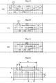
- Figures 2 - 6 show stitching strip portions with Abheftlöchern the Abrollb selected invention, in which the markings are in the form of holes next to the perforation along the direction.
- Preferred as Abheftlöcher are two double holes as in Figures 2-4 shown or two double holes together with a slot or longitudinal slot as in FIG. 4 shown.
- the stitching strip portions of the unwinding tape according to the invention have picking holes. Therefore, the present invention also relates to a Abrollband for singling in stitching strips comprising at least two Abheftlöcher, equidistant perforations for engaging a spiked roller and a label for authentication and for determining the nature and quality of the Abrollbandes and the length of the separated adhesive strips by a sensor, wherein the Abrollband from a HeftstMail with Abheftlöchern and with equidistant perforations along the direction of engagement of a spiked roller, the HeftstMailband unilaterally covering, continuous adhesive film and the adhesive film covering protective tape, and wherein in the HeftstMailband along the direction identical identifications with a predetermined distance for authentication and are provided for determining the type and quality of the Abrollbandes and the length of the individual stitching strips by a sensor.
- a Abrollband for singling in stitching strips comprising at least two Abheftlöcher, equidistant
- the stitching strip portions of the inventive unwind strip 4 include stitching holes in two pairs, equidistant perforations for engaging a spiked roller, and identification for authentication and determination of the nature and quality of the unwinding strip and the length of the singulated stitching strips by a sensor, wherein the unwinding strip consists of a Heftstsammlungband with Abheftlöchern and with equidistant perforations along the direction of engagement of a spiked roller, the HeftstMailband unilaterally covering, continuous adhesive film and the adhesive film covering protective tape, and wherein in the HeftstMailband along the direction identical identifiers with a predetermined distance for authentication and for determining the Type and quality of the Abrollbandes and the length of the separated stitching strips are provided by a sensor.
- the stitching strip portions of the inventive unwind strip 4 comprise stitch holes in two pairs and a centrally located slot along the direction of passing a banderole, equidistant perforations for engaging a spiked roller, and identification for authentication and determination of the nature and quality of the unwinding strip and length the separated stitching strip by a sensor
- the Abrollband consists of a Heftstsammlungband with Abheftlöchern and / or slots along the direction, and with equidistant perforations along the direction of engagement of a spiked roller, a HeftstMakeband unilaterally covering, continuous adhesive film and a protective film covering the adhesive tape
- identical Markings are provided with a predetermined distance for authentication and for determining the nature and quality of the Abrollbandes and the length of the individual stitching strips by a sensor.
- the present invention also relates to a Abrollband for singling in stitching strips, which as Abheftlöcher two double holes and optionally a centrally located slot along the direction for performing a band and equidistant perforations for engaging a spiked roller and a label for authentication and for determining the type and quality the Abrollbandes and the length of the separated stitching strips by a sensor, wherein the Abrollband from a HeftstMail with Abheftlöchern and / or slots along the direction, and with equidistant perforations along the direction of engagement of a spiked roller, the HeftstMailband unilaterally covering, continuous adhesive film and a protective tape covering the adhesive film, and wherein in the HeftstMailband along the direction identical identifications with a predetermined distance for authentication and for determining the type and quality t of Abrollbandes and the length of the separated fastening strip are provided by a sensor.
- the markings are not covered by the guard band.
- the markings are different from the perforations and also different from the tacking double holes and the optional slots.
- the perforations in turn are different from the binned double holes and the optional slots.
- the distance d of the punch holes of a hole pair depends on the size of the hole and the type.
- the distance d is preferably constant, so that all the stitching strips of a roll-off tape have pairs of holes of identical spacing d.
- the distance d is 10 mm to 20 mm. It is also preferable if the distance d is 10 mm. Likewise, a distance d of 20 mm is preferred.
- the present invention also relates to a unwinding strip for stapling strips comprising 4 picking holes in two pairs, equidistant perforations for engaging a spiked roller and identification for authentication and determination of the nature and quality of the unwinding strip and the length of the singulated binding strips by a sensor
- the unwinding tape consists of a stitching tape with picking holes and slots along the Running direction, and with equidistant perforations along the running direction for engaging a spiked roller, a tacking tape unilaterally covering, continuous adhesive film and a protective film covering the adhesive film and wherein the distance d of the Abheftlöcher a hole pair 10 mm to 20 mm, and wherein in the HeftstMail along the direction identical identifications are provided with a predetermined distance for authentication and for determining the nature and quality of the Abrollbandes and the length of the individual stitching strips by a sensor.
- the stitching strip portions of the inventive unwind strip 4 include picking holes in two pairs and a centrally located slot along the direction of passing a banderole, equidistant perforations for engaging a spiked roller, and identification for authentication and determination of the nature and quality of the unwinding web as well as Length of the individual stitching strips by a sensor, wherein the unwinding strip consists of a Heftstsammlungband with Abheftlöchern and slots along the direction, and with equidistant perforations along the direction of engagement of a spiked roller, a HeftstMakeband unilaterally covering, continuous adhesive film and a protective film covering the adhesive tape and wherein the distance d of the Abheftlöcher a hole pair is 10 mm to 20 mm, and wherein in the HeftstMailband along the direction identical identifications with a predetermined distance for authentication and for determining the type and quality of the Abrollbandes and the length of the individual stitching strips are provided by a sensor
- the unwinding strip according to the invention may be provided with slots, wherein each stitching strip section has a slot along the direction of travel with respect to the adhesive strip.
- the slot allows several documents provided with the stitching strip according to the invention to be firmly bound to a banderole. Documents that are firmly connected to each other via the band guided through the slots can not be replaced or removed due to the bonding of the band. They are closed or sealed with it. This is particularly advantageous for document collections where it must be ensured that no subsequent change has been or can be made.
- the slot on the stitching strip according to the invention is closed, ie it has no open ends, through which, for example, a closed or glued banderole can be subsequently removed without causing the banderole must be destroyed.
- the slot preferably extends in the longitudinal direction of the stitching strip and is preferably arranged centrally in the longitudinal direction of the stitching strip on the stitching strip. If the stitching strip is additionally equipped with at least two picking holes, the slot is preferably located between the picking holes. If the Abheftlöcher arranged in pairs of holes, such as a 4-hole perforation, so the slot is located in the longitudinal direction preferably between the pairs of holes on the stitching strip.
- the present invention also relates to a Abrollband for singling in stitching strips having a centrally disposed slot along the direction for performing a band, equidistant perforations for engaging a spiked roller and a label for authentication and to determine the nature and quality of the Abrollbandes and the length of the comprising a stitching strip by a sensor
- the unwinding strip consists of a HeftstMailband with slots along the direction and with equidistant perforations along the direction of engagement of a spiked roller, a HeftstMailband unilaterally covering, continuous adhesive film and a protective film covering the adhesive film, and wherein in the HeftstMailband along the direction identical identifiers with a predetermined distance for authentication and to determine the nature and quality of the Abrollbandes and the length of the separated HeftstMake by a Sensor are provided. (please refer FIG. 5 ).
- the stitching strips of the inventive unwind strip comprise a closed slot for passing a banderole, equidistant perforations for engaging a spiked roller, and a tag for authenticating and determining the nature and quality of the unwinding strip and the length of the singulated tacking strips by a sensor, wherein the unwinding strip from a HeftstMailband with closed slots and with equidistant perforations along the direction of engagement of a spiked roller, the HeftstMailband unilaterally covering, continuous adhesive film and the adhesive film covering protective tape, and wherein in the HeftstMailband along the direction identical identifiers with a predetermined distance for authentication and to determine the nature and quality of the Abrollbandes and the length of the separated adhesive strips are provided by a sensor.
- the stitching strips of the inventive unwinding belt comprise at least two stitching holes and a closed slot for passing a band, equidistant perforations for engaging a spiked roller and a marking for authentication and for determining the type and quality of the unwinding strip and the length of the separated binding strips by a
- the unwinding belt is comprised of a tacking tape having picking holes, closed slots and equidistant perforations along the running direction for engaging a spiked roller, a continuous adhesive film overlying the binding tape and a protective tape covering the adhesive film, and wherein in the stitching tape along the direction of travel Identical identifications with a predetermined distance for authentication and for determining the type and quality of the Abrollbandes and the length of the separated adhesive strips by a n sensor are provided.
- the stitching strips of the inventive unwinding web comprise at least two picking holes and a centrally disposed slot along the direction of passing a banderole, equidistant perforations for engaging a spiked roller, and identification for authentication and determination of the nature and quality of the unwinding web and the length of the unwinding web isolated stitching strip by a sensor
- the unwinding strip consists of a Heftstsammlungband with Abheftlöchern, with slots and equidistant perforations along the direction of engagement of a spiked roller, a HeftstMakeband unilaterally covering, continuous adhesive film and a protective film covering the adhesive tape, and wherein in the HeftstMailband along the direction identical identifications with a predetermined distance for authentication and to determine the nature and quality of the Abrollbandes and the length of the separated Heftst Tires are provided by a sensor.
- the slit for passing a banderole preferably has a length s of 40 mm to 50 mm, more preferably 42 mm to 48 mm and most preferably a length of 45 mm.
- the present invention also relates to a unwinding belt for singling in tacking strips having at least two picking holes and / or a centrally disposed slot along the direction of travel of 40mm to 50mm length for passing a banderole, equidistant perforations for engaging a spiked roller and marking for authentication and for determining the nature and quality of the Abrollbandes and the length of the separated adhesive strips by a sensor, wherein the Abrollband from a HeftstMail with Abheftlöchern and / or slots along the direction and with equidistant perforations along the direction of engagement of a Spiked roller, a tape covering the tape on one side, continuous adhesive film and a protective film covering the adhesive tape, and wherein in the HeftstMailband along the direction identical identifier
- the stitching strip sections of the unwinding strip according to the invention can in principle have any desired width b and an arbitrary length l.
- the size of the stitching strip sections of the unwinding strip according to the invention preferably corresponds to the European standard with a length I of 111 mm or the Scandinavian standard with a length of 133.3 mm.
- the present invention also relates to a unwinding roll for singling in strips of 111 mm length, comprising at least two picking holes and / or a centrally located slot along the direction of passing a banderole, equidistant perforations for engaging a spiked roller and a marking for authentication and for determining the type and quality of the Abrollbandes and the length of the separated adhesive strips by a sensor, wherein the Abrollband from a HeftstMail with Abheftlöchern and / or slots along the direction and with equidistant perforations along the direction of engagement of a spiked roller, the HeftstMail one-sided covering, continuous adhesive film and a protective tape covering the adhesive film, and wherein in the HeftstMailband along the direction identical identifications with a predetermined distance for authentication and for determining the Ar t and quality of the Abrollbandes and the length of the separated stitching strips are provided by a sensor.
- the present invention also relates to a Abrollband for separation into adhesive strips having a length of 133.3 mm, the at least two Abheftlöcher and / or a centrally disposed slot along the direction for performing a band, equidistant perforations for engaging a spiked roller and a marking for Authentication and for determining the nature and quality of the Abrollbandes and the length of the individual stitching strips by a sensor, wherein the Abrollband from a HeftstMail with Abheftlöchern and / or slots along the direction and with equidistant perforations along the direction of engagement of a spiked roller, a the HeftstMail one-sided covering, continuous adhesive film and a protective film covering the adhesive film, and wherein in the HeftstMailband along the direction identical identifications with a predetermined distance for authentication and for determining the type and quality of the Abrollbandes and the length of the individual stitching strips are provided by a sensor.
- the stitching strip portions of the inventive unwind strip 4 include picking holes in two pairs and a centrally located slot along the direction of passing a banderole, equidistant perforations for engaging a spiked roller, and identification for authentication and determination of the nature and quality of the unwinding web as well as Length of the individual stitching strips by a sensor, wherein the unwinding strip consists of a Heftstsammlungband with Abheftlöchern and slots along the direction, and with equidistant perforations along the direction of engagement of a spiked roller, a HeftstMail unilaterally covering, continuous adhesive film and a protective film covering the adhesive tape and wherein the spacing d1 of the pairs of holes on a tacking strip is 60 mm and the tacking strip is 111 mm long, and wherein in the tacking tape along the direction of travel identically identifies conditions with a predetermined distance for authentication and to determine the nature and quality of the Abrollbandes and the length of the separated
- the stitching strip portions of the inventive unwind strip 4 include picking holes in two pairs, equidistant perforations for engaging a spiked roller and identification for authentication and for determining the nature and quality of the unwinding strip and the length of the singulated binding strips by a sensor, the unwinding strip being a stitching tape with Abheftlöchern and with equidistant perforations along the direction of engagement of a spiked roller, the HeftstMailband unilaterally covering, continuous adhesive film and the adhesive film covering protective tape and wherein the distance d1 of the hole pairs on a Heftstsammlung 60 mm and the HeftstMake 111 mm long and wherein in the stitching tape along the direction identical identifications with a predetermined distance for authentication and for determining the nature and quality of the Abrollbandes and the length of verei nzelten stitching strips are provided by a sensor.
- the stitching strip portions of the inventive unwind strip 4 comprise stitching holes in two pairs and a centrally located slot along the direction of passing a banderole, equidistant perforations for engaging a spiked roller, and a tag for authenticating and determining the nature and quality of the unwinding belt, and the length of the singulated tacking strips by a sensor
- the unwinding belt comprising a tacking tape with picking holes and slots along the direction of travel, and with equidistant perforations along the running direction for engaging a spiked, a tacking tape and wherein the distance d1 of the pairs of holes on a stitching strip is 71 mm and the stitching strip is 133.3 mm long, and wherein in the stitching strip along the direction identical identifications with a predetermined distance for authentication and are provided for determining the type and quality of the Abrollbandes and the length of the individual stitching strips by a sensor.
- the stitching strip portions of the inventive unwind strip 4 include picking holes in two pairs, equidistant perforations for engaging a spiked roller and identification for authentication and for determining the nature and quality of the unwinding strip and the length of the singulated binding strips by a sensor, the unwinding strip being a stitching tape with Abheftlöchern and with equidistant perforations along the direction of engagement of a spiked roller, the HeftstMailband unilaterally covering, continuous adhesive film and a protective film covering the adhesive tape and wherein the distance d1 of the hole pairs on a HeftstMail is 71 mm and the HeftstMake 133.3 mm long, and wherein in the HeftstMailband along the direction identical identifications with a predetermined distance for authentication and to determine the nature and quality of the Abrollbandes and the length of the ver individual stitching strips are provided by a sensor.
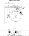
- FIG. 1 shows a device (1) for automatic and waste-free application of the adhesive strips on sheets, in which the inventive unwinding roll (3) on a take-off roll (2) is mounted.
- the stitching tape (4) is guided via a guide means (6) to a spiked roller (7) acting as a feed device, the protective tape (10) of the adhesive film (18) removed via a deflection roller (8), and forwarded to an applicator (12).
- a guide means (7) can serve for example a rail.
- the present invention also relates to a tacking strip applied to a sheet by means of a device (1), comprising a take-off roll (2) provided with a roll-off strip according to any one of claims 1-13
- Sensor (5) for the detection of the markings (20) equipped guide means (6) acting as a feed device spiked roller (7) with drive (15), a with a cutting device (11) equipped An horrbalken with drive (13) and a control unit (14 ) for controlling the spiked roller drive (15) and the applicator drive (13) for automatically loading and positioning the tacking tape (4) in accordance with the identifications (20) detected by the sensor (5).
- a sensor is attached, which detects the markings (20) of the HeftstMailes (4) and in contact with a control unit (14).
- the guide means is an immovable component of the device according to the invention, so that additional loading of the cables and connections connected to the sensor does not occur due to movement of the sensor.
- the feed device is a spiked roller (7) which has pins at regular intervals so that it engages in the regularly running perforation (19) of the stitching tape (4).
- the spiked roller is driven by a drive (15), which is preferably a stepper motor, and is in contact with the control unit (14).
- the guide means (7) may also be a rail, so that the device for applying stripe of a rolling strip with markings on sheets, a take-off roll, equipped with a sensor for detecting the mark guide means acting as a feed device spiked roller with drive, an applicator with drive and a control unit for controlling the spiked roller drive and the applicator drive for automatically loading and positioning the tacking tape in accordance with the identifications detected by the sensor, wherein the guide means is a rail.
- the application device (12) preferably consists of a stamp or a pressure bar, which applies the tacking strip (17) to the sheet goods located in the sheet-goods guide (16).
- the blade guide ensures that the stitching strip is applied to the sheet in the correct position.
- the application device (12) is moved via the drive (13) in the direction of sheet guide (16).
- the drive (13) is connected to the control unit (14).
- the control unit (14) can be mounted anywhere on the device, for example on the applicator (12).
- the separation into stitching strips (17) takes place on the applicator device (12) by means of a cutting device (11).
- the Cutting device is preferably a knife.
- the knife is either directly on the applicator or may be mounted between the spiked roller and the applicator. In both cases, the separation takes place to HeftstMail the hub of the applicator in the direction of sheet guide.
- the tacking tape applicator apparatus may include a rolling stock with markings on sheets, a take-off roll, a guide means equipped with a mark detection sensor, a power take-up sprocket with drive, a power take-up device and a sprocket drive control unit the applicator drive for automatically loading and positioning the tacking tape in accordance with the identifications detected by the sensor, the applicator being a driving pressure bar equipped with a cutting device.
- the control unit (14) controls, according to the markings (20) on the tacking tape (4) detected by the sensor (5), the advancement of the tacking tape over the drive of the spiked roller (15) and the application of the tacking tape to the sheet material via the drive of the applicator (13).
- the control unit determines the length and type of the stitching strip on the basis of the number of steps required by the drive of the spiked roller so that the sensor detects the next marking starting from a detected label. Based on the automatically detected tape type, the tape tab is automatically retracted, i. so guided on the applicator that a tape strip can be singled in the correct position and applied to the sheets.
- the term "inserting” is understood here to mean that the user of the device attaches a unwinding roll to the unwinding roll, guides the stitching strip tape over the guide means to the spiked roll and separates the protective tape from the stitching strip tape by way of a deflection roll in front of the spiked roll.
- the insertion does not mean that the user guides the tape strip to the applicator or positioned on the applicator. Not even a positioning of the tacking tape on the spiked roller is required, as was necessary in the prior art embodiments, where there were three false and only one correct way for a spiked roller with, for example, 8 spines to perforate the tacking tape with perforation on the spiked roller to lay.
- waste-free insertion that when inserting the Abrollbandes no surplus and no longer usable adhesive strips incurred on the applicator and must be removed by the user before the first application to sheets of HeftstMakeband.
- the term “retraction” or “positioning” is understood to mean that the inserted tacking tape is oriented on the applicator so that a tacking tape can be singulated in position and applied to sheets.
- the device described herein may additionally be provided with a display that indicates to the user the consumption of stitching strips and / or a roll-off tape jam.
- the tacking tape applicator apparatus may include a roll-off tape with markings on sheets, a take-off roll, a guide means equipped with a detection sensor, a power take-up sprocket with drive, a power take-up device, a sprocket drive control unit, and the like the applicator drive for automatically loading and positioning the tacking tape in accordance with the identifications detected by the sensor and a display for the indication of the tacking tape consumption and / or a Abrollbandstaus.
- the device for applying adhesive strips to sheets may be part of a folding machine that folds sheets and then automatically provides the folded sheets with tape.
- the folding machine may also include a device for applying adhesive strip from a rolling strip with markings on sheet goods, a take-off roll, equipped with a sensor for detecting the marks guide means, acting as a feed device spiked roller with drive, an applicator with drive and a control unit for Controlling the spiked roller drive and the applicator drive for automatically loading and positioning the tacking tape in accordance with the identifications detected by the sensor.
Landscapes
- Folding Of Thin Sheet-Like Materials, Special Discharging Devices, And Others (AREA)
- Adhesive Tapes (AREA)
Abstract
Description
- Die vorliegende Erfindung betrifft ein Halbzeug, genauer ein Abrollband zur Vereinzelung in Heftstreifen, die mindestens zwei Abheftlöcher und/oder einen mittig angeordneten Schlitz entlang der Laufrichtung zum Durchführen einer Banderole, äquidistante Perforierungen zum Eingreifen einer Stachelwalze und eine Kennzeichnung zur Authentifizierung und Bestimmung der Art und Qualität des Abrollbandes sowie der Länge der vereinzelten Heftstreifen durch einen Sensor umfassen. Das Abrollband ist derart ausgestaltet, dass es von einer Vorrichtung zur Aufbringung von Heftstreifen von einem Abrollband auf Blattware, mittels eines Sensors am Führungsmittel automatisch erkannt und über eine als Vorschubeinrichtung wirkende Stachelwalze eingezogen werden kann und die Heftstreifen durch einen mit einer Schneidevorrichtung ausgestattetem Andruckbalken abfallfrei auf Blattware aufgebracht werden können.
- Ein Heftstreifenautomat klebt automatisch von unten Heftstreifen gegen ausgefaltete Blattware bzw. die letzte Lage gefalteter Blattware. So können Dokumente, Zeichnungen, Pläne unterschiedlicher Formate gleichmäßig mit Heftstreifen fest und einreißsicher versehen werden. Durch die Verwendung von Heftstreifen mit Abheftlöchern kann die Blattware abgeheftet werden, ohne dass eine umständliche Schrägfalte eingebracht oder die Blattware nachträglich gelocht werden muss. Zudem kann Blattware, insbesondere amtliche Dokumente mittels Heftstreifen mit einem geschlossenen Schlitz über eine Banderole, die durch die Schlitze durchgeführt ist, verschlossen oder versiegelt werden.
- Dem Fachmann sind Heftstreifenautomaten für einen bestimmten Heftstreifentyp aus dem Stand der Technik bekannt.
WO 2004/039605 A2 offenbart einen Heftstreifenautomaten für das Aufbringen von Heftstreifen auf Blattware, der in der Lage ist, verschiedene Lochanzahltypen, wie z.B. Zweifach- oder Vierfachlochung auf Blattware aufzubringen. Dabei wird der Transport des Heftstreifenbandes zur Aufbringeinrichtung über eine als Vorschubeinrichtung vorgesehene Stachelrolle, deren stachelförmige Zapfen in Transportlöcher des Heftstreifenbandes eingreifen, realisiert. Entsprechend der Länge des Heftstreifens und der gewünschten Lochanzahl wird die Stachelrolle um einen vorgegebenen Winkel gedreht, so dass der Heftstreifen der Aufbringeinrichtung zugeführt wird und auf die Blattware aufgebracht werden kann. Eine unterschiedliche Lochanzahl auf dem Heftstreifen kann nur mit einem speziellen Heftstreifenband erreicht werden, bei dem die Löcher normgerechte Abstände zwischen den aneinander angrenzenden Abschnitten einhalten. Verschiedene Heftstreifentypen, wie beispielsweise nach dem europäischen oder skandinavischen Standard können mit diesem Heftstreifenautomaten nicht verarbeitet werden. - Die internationale Patentanmeldung
WO 2015/135653 A1 offenbart einen Heftstreifenautomaten zum Aufbringen von Heftstreifen auf Blattware, bei dem der Transport des Heftstreifenbandes über das Aufwickeln des Klebefilm bedeckenden Abdeckbandes erfolgt. Dazu wird das Abdeckband über ein Umlenkmittel vom Heftstreifenband getrennt und auf einer Rolle aufgewickelt, während durch das Aufwickeln des Abdeckbandes der Heftstreifen auf einen Andruckbalken geführt wird. Das Heftstreifenband wird bei dieser Ausführungsform in Laufrichtung befördert, indem das Abdeckband über eine Umlenkrolle entgegen der Laufrichtung des Heftstreifenbandes bewegt und aufgewickelt wird. Der Andruckbalken ist mit einem optischen Sensor ausgestattet, der die Abheftlöcher des Heftstreifenbandes detektiert, und so unterschiedliche Heftstreifentypen automatisch erkannt und über eine Steuereinheit verarbeitet werden können. Der Vorschub durch das Aufwickeln des Abdeckbandes führt jedoch zu diversen Störungen. Das Abdeckband ist nicht sonderlich reißfest, da es eigentlich nur die Aufgabe hat, den Klebefilm abzudecken und nicht durch Zug für das Abwickeln und Befördern des gesamten Heftstreifenbandes verantwortlich zu sein. Reißt daher das Abdeckband, steht die gesamte Vorrichtung still, muss manuell geöffnet und das Heftstreifenband manuell erneut eingefädelt werden. Zudem ist diese Antriebsart einer Stachelwalze deutlich unterlegen, da zum einen das Abdeckband eine gewisse Elastizität besitzt, welche den präzisen Vorschub des Heftstreifenbandes erschwert. Zum anderen ist das Abdeckband aufgrund seiner Aufgabe, den Klebefilm so abzudecken, dass beim Abziehen des Abdeckbandes kein Kleber daran verbleibt, sondern der Kleber gänzlich auf dem Heftstreifenband zurückbleibt, mit einer leicht gleitfähigen Oberfläche versehen, wodurch sich das Abdeckband sehr schlecht auf sich selbst aufwickeln lässt. Selbst wenn das Aufwickeln des Abdeckbandes fehlerfrei verläuft, so nimmt mit zunehmender Anzahl der Wicklungen des aufgewickelten Abdeckbandes der Durchmesser der Aufwicklung zu, so dass bei gleichbleibender Antriebsgeschwindigkeit das Abdeckband immer schneller aufgewickelt und damit das Heftstreifenband immer schneller befördert wird, was eine genaue Positionierung des Heftstreifenbandes recht schwierig macht. Darüber hinaus erzeugt das Aufwickeln des Abdeckbandes entgegen der Vorschubrichtung des Heftstreifenbandes beim Zuführen des Heftstreifenbandes auf den Andruckbalken Spannungen im Heftstreifenband, die eine ungenaue und ungleichmäßige Positionierung des Heftstreifens zur Folge haben. Ferner ermöglicht diese Art des Antriebs nur ein Abwickeln des Heftstreifenbandes von der Abwickelrolle aber keine Rückwärtsbewegung des Heftstreifenbandes, was eine Stachelwalze grundsätzlich ermöglicht. Die Vorrichtung gemäßWO 2015/135653 A1 weist somit vor allem hinsichtlich der Beförderung des Heftstreifenbandes deutliche Nachteile auf, welche es zu beheben gilt. - Ein weiterer Nachteil besteht darin, dass das Heftstreifenband nicht verlustfrei verarbeitet werden kann. Bei dieser Variante des Vorschubs wird beim Einlegen des Heftstreifenbandes in den Heftstreifenautomaten eine Länge von mehreren Heftstreifenabschnitten an überstehendem Abdeckband benötigt, damit das Abdeckband aufgerollt werden kann. Die entsprechenden Heftstreifen stehen zum Aufbringen auf die Blattware nicht zur Verfügung und müssen vom Nutzer des Heftstreifenautomatens manuell abgetrennt und entfernt werden. Das manuelle Abtrennen der überstehenden Heftstreifen stellt ein gewisses Sicherheitsrisiko und einen gewissen Aufwand für den Nutzer dar, da er innerhalb des Heftstreifenautomatens die Heftstreifen mit freigelegtem Klebefilm sauber und gerade abtrennen und ohne den Klebefilm versehentlich mit einem Bauteil der Vorrichtung in Berührung zu bringen, entnehmen muss.
- Ferner werden beim Einlegen des Heftstreifenbandes die Position und der Typ des Heftstreifens anhand der Abheftlöcher erst ermittelt, wenn ein vollständiger Heftstreifenabschnitt den Sensor auf dem Andruckbalken passiert hat. Dieser Heftstreifenabschnitt kann ebenfalls nicht mehr auf die Blattware aufgebracht werden und muss vom Nutzer manuell als Abfall entsorgt werden. Ein Heftstreifenband kann somit nicht abfallfrei in einen solchen Heftstreifenautomaten eingesetzt werden und der Aufwand des Einfädelns des Heftstreifenbandes bis hin zu dem Punkt, dass der Heftstreifenautomat einsatzbereit ist, ist insgesamt noch relativ hoch und kompliziert und damit bedienerunfreundlich.
- Ein Heftlochstreifen zum Abheften von Dokumenten in einem Ringbuch, wobei der Streifen mit Löchern ausgestattet ist, in denen jeweils ein Schlitz endet und dessen transparenter Rand mit Gummi zum Ankleben von Dokumenten versehen ist, wird in der Patentschrift
FR 633 478 A - Ein Halbmittel bestehend aus einer bandförmigen Trägerfolie, auf der eine Vielzahl von ablösbaren Heftstreifen quer zur Bandrichtung aufgebracht ist, wird in der europäischen Patentanmeldung
EP 0 864 442 A1 beschrieben. Die Heftstreifen besitzen einen klebenden Teil zur Anbringung an Blattware und einen nicht klebenden Bereich mit Abheftlöchern. Die Heftstreifen werden mittels einer Vorrichtung über eine Kante von der Trägerfolie abgelöst und auf ein Blatt geklebt. - Aufgabe der vorliegenden Erfindung ist es daher, ein Halbmittel in Form eines Abrollbandes zur Vereinzelung von Heftstreifen bereitzustellen, das derart ausgestaltet ist, dass das Abrollband abfallfrei und möglichst einfach in eine Vorrichtung zur Aufbringung von Heftstreifen auf Blattware eingelegt, automatisch erkannt, authentifiziert und eingezogen werden kann. Die zu vereinzelnden Heftstreifen des Abrollbandes sollen zudem für verschiedene Abheftformate geeignet sein und möglichst universell einsetzbar zum einen von der zugehörigen Vorrichtung erkannt werden und auch anstelle oder zusätzlich zur Abheftung das Zusammenbinden mittels Banderole zulassen.
- Diese Aufgabe wird durch die technische Lehre der unabhängigen Ansprüche der vorliegenden Erfindung gelöst. Weitere vorteilhafte Ausgestaltungen der Erfindung ergeben sich aus den abhängigen Ansprüchen, der Beschreibung sowie den Beispielen.
- Das erfindungsgemäße Abrollband zur Vereinzelung in Heftstreifen besteht aus einem Heftstreifenband mit Abheftlöchern und/oder Schlitzen entlang der Laufrichtung, und mit äquidistanten Perforierungen entlang der Laufrichtung zum Eingreifen einer Stachelwalze, einem das Heftstreifenband einseitig bedeckenden, durchgängigen Klebefilm, einem den Klebefilm abdeckendes Schutzband sowie entlang der Laufrichtung identische Kennzeichnungen mit vorbestimmtem Abstand zur Bestimmung der Art und Qualität des Abrollbandes sowie der Länge der vereinzelten Heftstreifen durch einen Sensor vorgesehen sind.
Das Abrollband kann mittels einer Vorrichtung zu Heftstreifen vereinzelt und auf Blattware aufgebracht werden, wobei die Vorrichtung eine Abwickelrolle, ein mit einem Sensor zur Detektion der Kennzeichnungen ausgestattetes Führungsmittel, eine als Vorschubeinrichtung wirkende Stachelwalze mit Antrieb, eine Aufbringeinrichtung mit Antrieb und eine Steuereinheit zur Steuerung des Stachelwalzenantriebs und des Aufbringeinrichtungsantriebs zur automatischen Beladung und Positionierung des Heftstreifenbandes gemäß den vom Sensor detektierten Kennzeichnungen umfasst. - Die Beförderung des perforierten Heftstreifenbandes mittels einer Stachelwalze hat deutliche Vorteile hinsichtlich der Präzision der Beförderung des Heftstreifenbandes und sehr geringen Störanfälligkeit und hat sich daher sehr bewährt. Zudem ist über einen Stachelwalzenantrieb auch grundsätzlich die Beförderung in beide Richtungen, d.h. in Abwickelrichtung als auch in Aufwickelrichtung des Heftstreifenbandes möglich, wodurch eine sehr präzise Positionierung des Heftstreifenbandes erfolgen kann.
- Zur Lösung der Aufgabe ist das erfindungsgemäße Abrollband mit Kennzeichnungen mit bzw. in vorbestimmtem Abstand entlang der Laufrichtung ausgestattet, die vom Sensor der Vorrichtung erkannt werden. Somit kann der Typ und die Position des Heftstreifenbandes automatisch von der Vorrichtung erkannt werden. Zudem ist der Sensor über eine Steuereinheit mit dem Antrieb der Stachelwalze und dem Antrieb der Aufbringeinrichtung verbunden, sodass der Vorschub des Heftstreifenbandes und das Aufbringen des Heftstreifens auf Blattware automatisch und ohne Eingreifen des Nutzers erfolgt.
- Die Kennzeichnungen im Abrollband haben aber drei Funktionen. Neben der Detektion der Position des Heftstreifenbandes, um ein abfallfreies Vereinzeln der Heftstreifen zu gewährleisten, wird durch die Kennzeichnungen auch die Art des Heftstreifenbandes erkannt wie z.B. zu vereinzelnde Heftstreifen mit beispielsweise Einfachlochung, mit Doppellochung sowie mit oder ohne Schlitz für eine Banderole usw.. Als dritte Funktion erfolgt über die Kennzeichnungen eine Authentifizierung des Abrollbandes zur Feststellung, ob es sich um ein für die Vorrichtung zum Schneiden und Anbringen der vereinzelten Heftstreifen geeignetes Abrollband handelt oder um ein Plagiat, welches bei Verwendung zu Fehlfunktionen führt oder sogar die Vorrichtung beschädigen könnte. Somit sind Kennzeichnungen des Abrollbandes so ausgestaltet, dass sie durch einen Sensor, vorzugsweise einen optischen Sensor erkannt werden können. Im Falle einer nicht erfolgten Authentifizierung wird vorzugsweise durch die Vorrichtung ein Warnsignal angezeigt oder ausgegeben oder die Vorrichtung stoppt, bis ein authentifiziertes Abrollband eingelegt wurde, um Fehlfunktionen bis hin zu Beschädigungen der Vorrichtung zu vermeiden.
- Dieses Führungsmittel ist zudem unbeweglich, so dass der Sensor an einem unbeweglichen Teil der Vorrichtung angebracht ist, was zu einer sehr geringen Störanfälligkeit und hohen Genauigkeit der Messung des Sensors führt.
- Der Vorschub durch die Stachelwalze wird entsprechend des erkannten Heftstreifentyps gesteuert, sodass unterschiedliche Heftstreifentypen mit unterschiedlichen Längen und Lochungen bzw. Aussparungen wie Schlitzen und Langlöchern, wie beispielsweise ein europäischer 2-Loch-Heftstreifen mit 111 mm Länge oder ein skandinavischer 2-Loch-Heftstreifen mit 134 mm Länge als auch ein französischer Heftstreifen mit Schlitz für eine Banderole von der erfindungsgemäßen Vorrichtung verarbeitet werden können.
- Der Typ und die Position des erfindungsgemäßen Heftstreifenbandes werden vom Sensor der Vorrichtung ermittelt, bevor das Heftstreifenband auf die Aufbringeinrichtung zugeführt wird. Dadurch kann beim Einlegen eines neuen Heftstreifenbandes in Form einer Rolle auf die Abwickelrolle das Heftstreifenband automatisch auf die Aufbringeinrichtung geführt und in die richtige Position zum Aufbringen auf die Blattware gebracht werden. Dies ist nur möglich, weil der Sensor sich an einem Führungsmittel mindestens eine Heftstreifenlänge entfernt von der Aufbringeinrichtung befindet und nicht an der Aufbringeinrichtung selbst, welche z.B. ein Stempel sein könnte.
- Zudem erkennt der Sensor bereits beim Einlegen einer Abwickelrolle, ob diese authentisch ist oder es sich um ein Plagiat minderer Qualität handelt, welche zu Störungen oder sogar Beschädigungen der Vorrichtung zum Aufbringen der Heftstreifen führen kann. Entsprechend warnt die Vorrichtung den Benutzer durch eine entsprechende Anzeige, dass das eingelegte Abrollband zu Funktionsstörungen führen kann, wenn es betrieben wird oder die Vorrichtung stellt ihre Funktion gänzlich ein, bis das Abrollband gegen ein authentifiziertes Abrollband ausgetauscht worden ist. Diese Authentifizierung erfolgt über die zusätzlichen Kennzeichnungen, welche nicht mit der Perforierung und auch nicht mit der Lochung identisch sind.
- Dies bedeutet, dass sich drei verschiedene Arten von funktionellen Bereichen auf dem Heftstreifen befinden, nämlich zum einen die Perforierung zum Eingreifen der Stacheln einer Stachelwalze, zum zweiten die Lochung in Form von beispielsweise einer Einfachlochung, Doppellochung, Schlitz oder Kombinationen aus Einfachlochung und Schlitz oder Doppellochung und Schlitz, welche zum Abheften in eine entsprechende Akte oder einen entsprechenden Ordner oder zum Durchführen einer Banderole dienen und zum dritten die Kennzeichnung, welche die Position des Heftstreifens zwecks verlustfreiem Vereinzeln, den Typ des Heftstreifens wie z.B. europäischer, skandinavischer oder französischer Typ und zur Authentifizierung des Abrollbandes und evtl. Erzeugung einer entsprechenden Warnung oder das Anhalten der Vorrichtung dient. Diese Funktionen der drei funktionellen Bereiche sind strikt getrennt, d.h. zwei Löcher der Perforierung dienen z.B. nicht für die Abheftung oder dienen nicht als Kennzeichnung für die Authentifizierung, die Kennzeichnungen für die Position, Typ und Authentifizierung dienen nicht für die Abheftung und auch nicht zum Eingreifen der Stachelwalze sofern es sich bei den Kennzeichnungen überhaupt um Löcher handelt und entsprechend dienen die Lochungen zum Abheften oder die Schlitze zum Durchführen von Banderolen nicht als Kennzeichnung für Position, Typ und Authentifizierung und auch nicht zum Eingreifen der Stachelwalze.
- Die Perforierung ist somit verschieden und nicht identisch mit den Kennzeichnungen und die Kennzeichnungen sind verschieden und nicht identisch mit den Abheftlöchern und/oder Schlitzen und die Abheftlöcher und/oder Schlitze sind verschieden und nicht identisch zur Perforierung.
- Die vorliegende Erfindung betrifft somit ein Abrollband (3) zur Vereinzelung in Heftstreifen (17), die mindestens zwei Abheftlöcher und/oder einen mittig angeordneten Schlitz entlang der Laufrichtung zum Durchführen einer Banderole, äquidistante Perforierungen (19) zum Eingreifen einer Stachelwalze (7) und eine Kennzeichnung (20) zur Authentifizierung und Bestimmung der Art und Qualität des Abrollbandes (3) sowie der Länge der vereinzelten Heftstreifen (17) durch einen Sensor umfassen,
wobei das Abrollband (3) aus einem Heftstreifenband (4) mit Abheftlöchern und/oder Schlitzen entlang der Laufrichtung, und mit äquidistanten Perforierungen (19) entlang der Laufrichtung zum Eingreifen einer Stachelwalze (7), einem das Heftstreifenband (4) einseitig bedeckenden, durchgängigen Klebefilm (18) und einem den Klebefilm (18) abdeckendes Schutzband (10) besteht,
und wobei in dem Heftstreifenband (4) entlang der Laufrichtung identische Kennzeichnungen (20) mit vorbestimmtem Abstand zur Authentifizierung und Bestimmung der Art und Qualität des Abrollbandes (3) sowie der Länge der vereinzelten Heftstreifen (17) durch einen Sensor vorgesehen sind. - Der Begriff "zum Eingreifen einer Stachelwalze (7)" bezeichnet konkreter natürlich das Eingreifen der Stacheln einer Stachelwalze (7).
- Vorzugsweise betrifft die vorliegende Erfindung ein Abrollband (3) zur Vereinzelung in Heftstreifen (17), die mindestens zwei Abheftlöcher und/oder einen mittig angeordneten Schlitz entlang der Laufrichtung zum Durchführen einer Banderole, äquidistante Perforierungen (19) zum Eingreifen einer Stachelwalze (7) und eine Kennzeichnung (20) zur Authentifizierung und Bestimmung der Art und Qualität des Abrollbandes (3) sowie der Länge der vereinzelten Heftstreifen (17) durch einen Sensor umfassen,
wobei das Abrollband (3) aus einem Heftstreifenband (4) mit Abheftlöchern und/oder Schlitzen entlang der Laufrichtung, und mit äquidistanten Perforierungen (19) entlang der Laufrichtung zum Eingreifen einer Stachelwalze (7), einem das Heftstreifenband (4) einseitig bedeckenden, durchgängigen Klebefilm (18) und einem den Klebefilm (18) abdeckendes Schutzband (10) besteht,
und wobei in dem Heftstreifenband (4) entlang der Laufrichtung identische Kennzeichnungen (20) mit vorbestimmtem Abstand zur Authentifizierung und Bestimmung der Art und Qualität des Abrollbandes (3) sowie der Länge der vereinzelten Heftstreifen (17) durch einen Sensor vorgesehen sind und die Kennzeichnungen verschieden und nicht identisch mit den äquidistanten Perforierungen (19) und den Abheftlöchern und/oder Schlitzen sind. - Die Begriffe "verschieden und nicht identisch" bedeuten, dass auch keine teilweise Übereinstimmung vorliegt, z.B. in dem Sinne, dass zwei Löcher der insgesamt z.B. 20 Löcher umfassenden Perforierung auf einem Heftstreifen zum Abheften dienen oder dass ein Loch der Perforierung oder ein Loch der Abheftlöcher als Kennzeichnung dienen. Perforierungen, Abheftlöcher und Kennzeichnungen sind strikt voneinander verschieden und auch an unterschiedlichen Stellen auf dem Heftstreifen angebracht.
- Die vorliegende Erfindung betrifft somit ein Abrollband (3) zur Vereinzelung in Heftstreifen (17), die mindestens zwei Abheftlöcher und/oder einen mittig angeordneten Schlitz entlang der Laufrichtung zum Durchführen einer Banderole, äquidistante Perforierungen (19) zum Eingreifen einer Stachelwalze (7) und eine Kennzeichnung (20) zur Authentifizierung und Bestimmung der Art und Qualität des Abrollbandes (3) sowie der Länge der vereinzelten Heftstreifen (17) durch einen Sensor umfassen,
wobei das Abrollband (3) aus einem Heftstreifenband (4) mit Abheftlöchern und/oder Schlitzen entlang der Laufrichtung, und mit äquidistanten Perforierungen (19) entlang der Laufrichtung zum Eingreifen einer Stachelwalze (7), einem das Heftstreifenband (4) einseitig bedeckenden, durchgängigen Klebefilm (18) und einem den Klebefilm (18) abdeckendes Schutzband (10) besteht,
und wobei in dem Heftstreifenband (4) entlang der Laufrichtung identische Kennzeichnungen (20) mit vorbestimmtem Abstand zur Authentifizierung und Bestimmung der Art und Qualität des Abrollbandes (3) sowie der Länge der vereinzelten Heftstreifen (17) durch einen Sensor vorgesehen sind und die Kennzeichnungen, die äquidistanten Perforierungen (19) und die Abheftlöcher und/oder Schlitze an verschiedenen Positionen auf dem Heftstreifenband (4) angeordnet sind. - Das erfindungsgemäße Abrollband (3) vereint etliche Vorteile und löst mehrere Probleme gleichzeitig, wofür es im Stand der Technik nur partielle oder gar keine Lösungen gibt. Es wird automatisch erkannt, verlustfrei in die Vorrichtung eingezogen und exakt durch den Vorschub mittels Stachelwalze platziert, schützt die Vorrichtung vor Fehlfunktionen und Beschädigungen und kann für unterschiedlichste Formate an Blattware und unterschiedlichste Arten von Heftungen und/oder Bindungen eingesetzt werden.
- Im Gegensatz zu den im Stand der Technik beschriebenen Lösungen, ist ein manuelles Eingreifen des Nutzers nach dem Einlegen des Heftstreifenbandes nicht mehr erforderlich, denn aufgrund der frühzeitigen Erkennung des Heftstreifentyps entsteht kein überschüssiger, nicht mehr verwendbarer Heftstreifenabfall, der vom Nutzer aus der Aufbringeinrichtung aufwendig und vorsichtig entfernt werden muss. Zudem entfällt die erste Positionierung des Heftstreifenbandes nach dem Einlegen des Heftstreifenbandes durch den Nutzer.
- Somit bestehen die Vorteile des erfindungsgemäßen Abrollbandes darin, dass das Heftstreifenband automatisch nach dem Einlegen in eine hierin beschriebene Vorrichtung durch den Nutzer in die Position zum Aufbringung auf die Blattware gebracht wird und dass keine überschüssigen, nicht mehr verwendbaren Heftstreifen als Abfall anfallen, die vom Nutzer nach dem Einlegen des Heftstreifenbandes aufwendig entfernt werden müssen.
- Weiterhin kann über den Sensor die Anzahl der aufgebrachten bzw. der noch auf dem Abrollband befindlichen Heftstreifen ermittelt werden und der Verbrauch an Heftstreifen bzw. die noch auf dem Abrollband vorhandenen restlichen Heftstreifen können zusätzlich über eine optionale Anzeige dargestellt werden.
- Die vorliegende Erfindung betrifft ein Abrollband (3) zur Vereinzelung in Heftstreifen (17), die mindestens zwei Abheftlöcher und/oder einen mittig angeordneten Schlitz entlang der Laufrichtung zum Durchführen einer Banderole, äquidistante Perforierungen (19) zum Eingreifen einer Stachelwalze (7) und eine Kennzeichnung (20) zur Bestimmung der Art und Qualität des Abrollbandes (3) sowie der Länge der vereinzelten Heftstreifen (17) durch einen Sensor umfassen,
wobei das Abrollband (3) aus einem Heftstreifenband (4) mit Abheftlöchern und/oder Schlitzen entlang der Laufrichtung, und mit äquidistanten Perforierungen (19) entlang der Laufrichtung zum Eingreifen einer Stachelwalze (7), einem das Heftstreifenband (4) einseitig bedeckenden, durchgängigen Klebefilm (18) und einem den Klebefilm (18) abdeckendes Schutzband (10) besteht, dadurch gekennzeichnet, dass in dem Heftstreifenband (4) entlang der Laufrichtung identische Kennzeichnungen (20) mit vorbestimmtem Abstand zur Bestimmung der Art und Qualität des Abrollbandes (3) sowie der Länge der vereinzelten Heftstreifen (17) durch einen Sensor vorgesehen sind. - Vorzugsweise betrifft die vorliegende Erfindung ein Abrollband (3) zur Vereinzelung in Heftstreifen (17), die mindestens zwei Abheftlöcher und/oder einen mittig angeordneten Schlitz entlang der Laufrichtung zum Durchführen einer Banderole, äquidistante Perforierungen (19) zum Eingreifen einer Stachelwalze (7) und eine Kennzeichnung (20) zur Authentifizierung und Bestimmung der Art und Qualität des Abrollbandes (3) sowie der Länge der vereinzelten Heftstreifen (17) durch einen Sensor umfassen,
wobei das Abrollband (3) aus einem Heftstreifenband (4) mit Abheftlöchern und/oder Schlitzen entlang der Laufrichtung, und mit äquidistanten Perforierungen (19) entlang der Laufrichtung zum Eingreifen einer Stachelwalze (7), einem das Heftstreifenband (4) einseitig bedeckenden, durchgängigen Klebefilm (18) und einem den Klebefilm (18) abdeckendes Schutzband (10) besteht,
und wobei in dem Heftstreifenband (4) entlang der Laufrichtung identische Kennzeichnungen (20) mit vorbestimmtem Abstand zur Authentifizierung und Bestimmung der Art und Qualität des Abrollbandes (3) sowie der Länge der vereinzelten Heftstreifen (17) durch einen Sensor vorgesehen sind und die Kennzeichnungen, Perforierungen und Abheftlöcher und/oder Schlitze sich an unterschiedlichen Orten auf dem Heftstreifen befinden. - Der Begriff "Kennzeichnungen" wie hierin verwendet bezieht sich auf Markierungen in den erfindungsgemäßen Abrollbändern, die durch einen Sensor erkannt werden können. Die Kennzeichnungen sind für einen Heftstreifentyp in Größe und Art identisch und befinden sich auf jedem Heftstreifenabschnitt eines Abrollbandes an derselben Stelle, sodass der Sensor der erfindungsgemäßen Vorrichtung in der Lage ist, die Art und Qualität des Abrollbandes sowie die Länge der einzelnen Heftstreifenabschnitte zu bestimmen. Auf jedem Heftstreifenabschnitt eines Abrollbandes befindet sich eine Kennzeichnung an derselben Stelle, sodass der Abstand der Kennzeichnungen durch die Länge des Heftstreifenabschnitts vorbestimmt ist.
- Die Kennzeichnungen der erfindungsgemäßen Abrollbänder können an einer beliebigen Stelle des Heftstreifenabschnitts vorhanden sein, mit Ausnahme der Perforierung zum Eingreifen einer Stachelwalze, eventuell vorhandener Abheftlöcher und eventuell vorhandener Schlitze zum Durchführen einer Banderole. Die Kennzeichnungen können sich auf einer Seite oder auf beiden Seiten der erfindungsgemäßen Abrollbänder befinden oder durchgehende Aussparungen sein. Sind die Kennzeichnungen auf der Seite mit dem durchgängigen Klebefilm und dem Schutzband oder sind die Kennzeichnungen durchgehende Aussparungen, so befinden sich die Kennzeichnungen auf dem Teil des Abrollbandes, das nicht mit dem Klebefilm und dem Abdeckband beschichtet ist, mit Ausnahme der Perforierung zum Eingreifen einer Stachelwalze, eventuell vorhandener Abheftlöcher und eventuell vorhandener Schlitze zum Durchführen einer Banderole.
- In einer Ausführungsform werden die Kennzeichnungen nicht von dem Schutzband überdeckt. Daher betrifft die vorliegende Erfindung auch ein Abrollband zur Vereinzelung in Heftstreifen, die mindestens zwei Abheftlöcher und/oder einen mittig angeordneten Schlitz entlang der Laufrichtung zum Durchführen einer Banderole, äquidistante Perforierungen zum Eingreifen einer Stachelwalze und eine Kennzeichnung zur Authentifizierung und zur Bestimmung der Art und Qualität des Abrollbandes sowie der Länge der vereinzelten Heftstreifen durch einen Sensor umfassen, wobei das Abrollband aus einem Heftstreifenband mit Abheftlöchern und/oder Schlitzen entlang der Laufrichtung, und mit äquidistanten Perforierungen entlang der Laufrichtung zum Eingreifen einer Stachelwalze, einem das Heftstreifenband einseitig bedeckenden, durchgängigen Klebefilm und einem den Klebefilm abdeckendes Schutzband besteht, und wobei in dem Heftstreifenband entlang der Laufrichtung identische Kennzeichnungen mit vorbestimmtem Abstand zur Authentifizierung und zur Bestimmung der Art und Qualität des Abrollbandes sowie der Länge der vereinzelten Heftstreifen durch einen Sensor vorgesehen sind, und die Kennzeichnungen nicht von dem Schutzband überdeckt werden.
- In allen hierin offenbarten Ausführungsformen sind vorzugsweise die Kennzeichnungen verschieden von den Perforierungen und auch verschieden von den Abheftlöchern und/oder Schlitzen. Die Perforierungen wiederum sind ihrerseits verschieden von den Abheftlöchern und/oder Schlitzen. In allen hierin offenbarten Ausführungsformen befinden sich vorzugsweise Kennzeichnungen und Perforierungen sowie Abheftlöcher und/oder Schlitze auf dem Abrollband (3) an unterschiedlichen Positionen. Damit befinden sich vorzugsweise auch die Kennzeichnungen und Perforierungen sowie Abheftlöcher und/oder Schlitze auf dem zu vereinzelnden und vereinzelten Heftstreifen an unterschiedlichen Positionen.
- In einer bevorzugten Ausführungsform befinden sich die Kennzeichnungen zwischen den Perforierungen in Laufrichtung des Abrollbandes, wobei der Abstand der Kennzeichnung zur nächstliegenden Perforierung zwischen 4 mm und 10 mm, bevorzugt 4 mm und 8 mm und am meisten bevorzugt 4,2 mm und 6,2 mm beträgt. Daher betrifft die vorliegende Erfindung auch ein Abrollband zur Vereinzelung in Heftstreifen, die mindestens zwei Abheftlöcher und/oder einen mittig angeordneten Schlitz entlang der Laufrichtung zum Durchführen einer Banderole, äquidistante Perforierungen zum Eingreifen einer Stachelwalze und eine Kennzeichnung zur Authentifizierung und zur Bestimmung der Art und Qualität des Abrollbandes sowie der Länge der vereinzelten Heftstreifen durch einen Sensor umfassen, wobei das Abrollband aus einem Heftstreifenband mit Abheftlöchern und/oder Schlitzen entlang der Laufrichtung, und mit äquidistanten Perforierungen entlang der Laufrichtung zum Eingreifen einer Stachelwalze, einem das Heftstreifenband einseitig bedeckenden, durchgängigen Klebefilm und einem den Klebefilm abdeckendes Schutzband besteht, und wobei in dem Heftstreifenband entlang der Laufrichtung identische Kennzeichnungen mit vorbestimmtem Abstand zur Authentifizierung und zur Bestimmung der Art und Qualität des Abrollbandes sowie der Länge der vereinzelten Heftstreifen durch einen Sensor zwischen den Perforierungen in Laufrichtung des Abrollbandes vorgesehen sind.
- Als Perforierung wird die Reihe von Aussparungen, vorzugsweise Löchern, entlang der Laufrichtung des Abrollbandes verstanden, in die die Stacheln der Stachelwalze eingreifen. Dementsprechend haben diese Aussparungen bzw. Löcher immer denselben Abstand zueinander, d.h. äquidistant, entsprechend der Abstände der Stacheln auf der Stachelwalze, welche in der Regel 5, 6, 7, oder 8 Stacheln und vorzugsweise 5 oder 6 Stacheln aufweist.
- Ein Heftstreifenabschnitt des erfindungsgemäßen Abrollbandes besitzt vorzugsweise 3 bis 10 äquidistante Perforierungen, bevorzugter 3 bis 8 äquidistante Perforierungen und noch bevorzugter 4 bis 6 äquidistante Perforierungen. Daher betrifft die vorliegende Erfindung auch ein Abrollband zur Vereinzelung in Heftstreifen, die mindestens zwei Abheftlöcher und/oder einen mittig angeordneten Schlitz entlang der Laufrichtung zum Durchführen einer Banderole, äquidistante Perforierungen zum Eingreifen einer Stachelwalze und eine Kennzeichnung zur Authentifizierung und zur Bestimmung der Art und Qualität des Abrollbandes sowie der Länge der vereinzelten Heftstreifen durch einen Sensor umfassen, wobei das Abrollband aus einem Heftstreifenband mit Abheftlöchern und/oder Schlitzen entlang der Laufrichtung, und mit äquidistanten Perforierungen entlang der Laufrichtung zum Eingreifen einer Stachelwalze, einem das Heftstreifenband einseitig bedeckenden, durchgängigen Klebefilm und einem den Klebefilm abdeckendes Schutzband besteht, wobei die Heftstreifen 3 bis 8 äquidistante Perforierungen aufweisen, und wobei in dem Heftstreifenband entlang der Laufrichtung identische Kennzeichnungen mit vorbestimmtem Abstand zur Authentifizierung und zur Bestimmung der Art und Qualität des Abrollbandes sowie der Länge der vereinzelten Heftstreifen durch einen Sensor vorgesehen sind.
- In einer bevorzugten Ausführungsform umfassen die Heftstreifenabschnitte des erfindungsgemäßen Abrollbands mindestens zwei Abheftlöcher und/oder einen mittig angeordneten Schlitz entlang der Laufrichtung zum Durchführen einer Banderole, äquidistante Perforierungen zum Eingreifen einer Stachelwalze und eine Kennzeichnung zur Authentifizierung und zur Bestimmung der Art und Qualität des Abrollbandes sowie der Länge der vereinzelten Heftstreifen durch einen Sensor umfassen, wobei das Abrollband aus einem Heftstreifenband mit Abheftlöchern und/oder Schlitzen entlang der Laufrichtung, und mit äquidistanten Perforierungen entlang der Laufrichtung zum Eingreifen einer Stachelwalze, einem das Heftstreifenband einseitig bedeckenden, durchgängigen Klebefilm und einem den Klebefilm abdeckendes Schutzband besteht, wobei die Heftstreifen 5 oder 6 äquidistante Perforierungen aufweisen, und wobei in dem Heftstreifenband entlang der Laufrichtung identische Kennzeichnungen mit vorbestimmtem Abstand zur Authentifizierung und zur Bestimmung der Art und Qualität des Abrollbandes sowie der Länge der vereinzelten Heftstreifen durch einen Sensor vorgesehen sind.
- Der Abstand p der äquidistanten Perforierungen liegt vorzugweise zwischen 18 mm und 27 mm, noch bevorzugter zwischen 20 mm und 25 mm, noch bevorzugter zwischen 21 mm und 23 mm noch bevorzugter zwischen 22 mm und 22,5 mm und am bevorzugtesten 22,225 mm. Daher betrifft die vorliegende Erfindung auch ein Abrollband zur Vereinzelung in Heftstreifen, die mindestens zwei Abheftlöcher und/oder einen mittig angeordneten Schlitz entlang der Laufrichtung zum Durchführen einer Banderole, äquidistante Perforierungen zum Eingreifen einer Stachelwalze und eine Kennzeichnung zur Authentifizierung und zur Bestimmung der Art und Qualität des Abrollbandes sowie der Länge der vereinzelten Heftstreifen durch einen Sensor umfassen, wobei das Abrollband aus einem Heftstreifenband mit Abheftlöchern und/oder Schlitzen entlang der Laufrichtung, und mit äquidistanten Perforierungen entlang der Laufrichtung zum Eingreifen einer Stachelwalze, einem das Heftstreifenband einseitig bedeckenden, durchgängigen Klebefilm und einem den Klebefilm abdeckendes Schutzband besteht, wobei der Abstand p der äquidistanten Perforierungen 20 mm bis 25 mm, und wobei in dem Heftstreifenband entlang der Laufrichtung identische Kennzeichnungen mit vorbestimmtem Abstand zur Authentifizierung und zur Bestimmung der Art und Qualität des Abrollbandes sowie der Länge der vereinzelten Heftstreifen durch einen Sensor vorgesehen sind.
- Die Kennzeichnungen der erfindungsgemäßen Abrollbänder können entweder Aussparungen, Löcher oder Vertiefungen im Abrollband oder Barcodes, QR-Codes, Labels, Aufkleber, Aufdrucke oder Etiketten sein, die vom Sensor der erfindungsgemäßen Vorrichtung erfasst werden können. Daher betrifft die vorliegende Erfindung auch ein Abrollband zur Vereinzelung in Heftstreifen, die mindestens zwei Abheftlöcher und/oder einen mittig angeordneten Schlitz entlang der Laufrichtung zum Durchführen einer Banderole, äquidistante Perforierungen zum Eingreifen einer Stachelwalze und eine Kennzeichnung zur Authentifizierung und zur Bestimmung der Art und Qualität des Abrollbandes sowie der Länge der vereinzelten Heftstreifen durch einen Sensor umfassen, wobei das Abrollband aus einem Heftstreifenband mit Abheftlöchern und/oder Schlitzen entlang der Laufrichtung, und mit äquidistanten Perforierungen entlang der Laufrichtung zum Eingreifen einer Stachelwalze, einem das Heftstreifenband einseitig bedeckenden, durchgängigen Klebefilm und einem den Klebefilm abdeckendes Schutzband besteht, und wobei in dem Heftstreifenband entlang der Laufrichtung identische Kennzeichnungen mit vorbestimmtem Abstand zur Authentifizierung und zur Bestimmung der Art und Qualität des Abrollbandes sowie der Länge der vereinzelten Heftstreifen durch einen Sensor vorgesehen sind, wobei die Kennzeichnungen Aussparungen, Löcher, Vertiefungen, Barcodes, QR-Codes, Labels, Aufkleber, Aufdrucke oder Etiketten sind.
- Vorzugsweise sind die Kennzeichnungen der erfindungsgemäßen Abrollbänder Löcher. Dabei können die Löcher eine beliebige Form besitzen. Sie können beispielsweise rund, oval, eckig, sternförmig, strichförmig oder quadratisch sein.
- Somit betrifft eine Ausführungsform der vorliegenden Erfindung ein Abrollband zur Vereinzelung in Heftstreifen, die mindestens zwei Abheftlöcher und/oder einen mittig angeordneten Schlitz entlang der Laufrichtung zum Durchführen einer Banderole, äquidistante Perforierungen zum Eingreifen einer Stachelwalze und eine Kennzeichnung zur Authentifizierung und zur Bestimmung der Art und Qualität des Abrollbandes sowie der Länge der vereinzelten Heftstreifen durch einen Sensor umfassen, wobei das Abrollband aus einem Heftstreifenband mit Abheftlöchern und/oder Schlitzen entlang der Laufrichtung, und mit äquidistanten Perforierungen entlang der Laufrichtung zum Eingreifen einer Stachelwalze, einem das Heftstreifenband einseitig bedeckenden, durchgängigen Klebefilm und einem den Klebefilm abdeckendes Schutzband besteht, und wobei in dem Heftstreifenband entlang der Laufrichtung identische Löcher mit vorbestimmten Abstand zur Authentifizierung und zur Bestimmung der Art und Qualität des Abrollbandes sowie der Länge der vereinzelten Heftstreifen durch einen Sensor vorgesehen sind.
- Eine besonders bevorzugte Ausführungsform der vorliegenden Erfindung betrifft ein Abrollband zur Vereinzelung in Heftstreifen, die mindestens zwei Abheftlöcher und/oder einen mittig angeordneten Schlitz entlang der Laufrichtung zum Durchführen einer Banderole, äquidistante Perforierungen zum Eingreifen einer Stachelwalze und eine Kennzeichnung zur Authentifizierung und zur Bestimmung der Art und Qualität des Abrollbandes sowie der Länge der vereinzelten Heftstreifen durch einen Sensor umfassen, wobei das Abrollband aus einem Heftstreifenband mit Abheftlöchern und/oder Schlitzen entlang der Laufrichtung, und mit äquidistanten Perforierungen entlang der Laufrichtung zum Eingreifen einer Stachelwalze, einem das Heftstreifenband einseitig bedeckenden, durchgängigen Klebefilm und einem den Klebefilm abdeckendes Schutzband besteht, und wobei in dem Heftstreifenband neben der Perforierung entlang der Laufrichtung identische Löcher mit vorbestimmten Abstand zur Authentifizierung und zur Bestimmung der Art und Qualität des Abrollbandes sowie der Länge der vereinzelten Heftstreifen durch einen Sensor vorgesehen sind.
- Es ist somit zwischen den Kennzeichnungen, welche vom Sensor erkannt werden und den Aussparungen bzw. Löchern der Perforierung, welche nicht dazu dienen, vom Sensor erkannt zu werden zu unterscheiden. Dies bedeutet, dass die Aussparungen oder Löcher der Perforierung selbst nicht als Kennzeichnungen dienen können, welche vom Sensor erkannt werden sollen. Es ist aber möglich, dass die Aussparungen oder Löcher der Perforierung weitere Ausgestaltungen wie z.B. Ränder, Umrandungen oder ähnliches aufweisen, welche als Kennzeichnungen dienen, die dann vom Sensor erkannt werden können.
- Das erfindungsgemäße Abrollband kann mit Abheftlöchern und/oder mit einem Schlitz zur Durchführung einer Banderole versehen sein. Die Anzahl an Abheftlöchern je Heftstreifenabschnitt kann beliebig sein; es müssen jedoch mindestens 2 sein. So kann ein Heftstreifenabschnitt dem 2-Lochstandard entsprechen und 4 Löcher aufweisen oder auch nur zwei Abheftlöcher besitzen. Die Abheftlöcher können eine beliebige Form aufweisen, sind aber vorzugsweise und zweckmäßig kreisförmig oder länglich rund, wie beim Skandinavischen Heftstreifentyp.
Figuren 2 - 6 zeigen Heftstreifenabschnitte mit Abheftlöchern der erfindungsgemäßen Abrollbänder, bei denen die Kennzeichnungen in Form von Löchern neben der Perforierung entlang der Laufrichtung sind. Bevorzugt als Abheftlöcher sind zwei Doppellöcher wie inFiguren 2 - 4 gezeigt oder zwei Doppellöcher zusammen mit einem Schlitz bzw. Längsschlitz wie inFigur 4 dargestellt. - In einer Ausführungsform besitzen die Heftstreifenabschnitte des erfindungsgemäßen Abrollbands Abheftlöcher. Daher betrifft die vorliegende Erfindung auch ein Abrollband zur Vereinzelung in Heftstreifen, die mindestens zwei Abheftlöcher, äquidistante Perforierungen zum Eingreifen einer Stachelwalze und eine Kennzeichnung zur Authentifizierung und zur Bestimmung der Art und Qualität des Abrollbandes sowie der Länge der vereinzelten Heftstreifen durch einen Sensor umfassen, wobei das Abrollband aus einem Heftstreifenband mit Abheftlöchern und mit äquidistanten Perforierungen entlang der Laufrichtung zum Eingreifen einer Stachelwalze, einem das Heftstreifenband einseitig bedeckenden, durchgängigen Klebefilm und einem den Klebefilm abdeckendes Schutzband besteht, und wobei in dem Heftstreifenband entlang der Laufrichtung identische Kennzeichnungen mit vorbestimmtem Abstand zur Authentifizierung und zur Bestimmung der Art und Qualität des Abrollbandes sowie der Länge der vereinzelten Heftstreifen durch einen Sensor vorgesehen sind.
- In einer Ausführungsform umfassen die Heftstreifenabschnitte des erfindungsgemäßen Abrollbands 4 Abheftlöcher in zwei Paaren, äquidistante Perforierungen zum Eingreifen einer Stachelwalze und eine Kennzeichnung zur Authentifizierung und zur Bestimmung der Art und Qualität des Abrollbandes sowie der Länge der vereinzelten Heftstreifen durch einen Sensor, wobei das Abrollband aus einem Heftstreifenband mit Abheftlöchern und mit äquidistanten Perforierungen entlang der Laufrichtung zum Eingreifen einer Stachelwalze, einem das Heftstreifenband einseitig bedeckenden, durchgängigen Klebefilm und einem den Klebefilm abdeckendes Schutzband besteht, und wobei in dem Heftstreifenband entlang der Laufrichtung identische Kennzeichnungen mit vorbestimmtem Abstand zur Authentifizierung und zur Bestimmung der Art und Qualität des Abrollbandes sowie der Länge der vereinzelten Heftstreifen durch einen Sensor vorgesehen sind.
- In einer Ausführungsform umfassen die Heftstreifenabschnitte des erfindungsgemäßen Abrollbands 4 Abheftlöcher in zwei Paaren und einen mittig angeordneten Schlitz entlang der Laufrichtung zum Durchführen einer Banderole, äquidistante Perforierungen zum Eingreifen einer Stachelwalze und eine Kennzeichnung zur Authentifizierung und zur Bestimmung der Art und Qualität des Abrollbandes sowie der Länge der vereinzelten Heftstreifen durch einen Sensor, wobei das Abrollband aus einem Heftstreifenband mit Abheftlöchern und/oder Schlitzen entlang der Laufrichtung, und mit äquidistanten Perforierungen entlang der Laufrichtung zum Eingreifen einer Stachelwalze, einem das Heftstreifenband einseitig bedeckenden, durchgängigen Klebefilm und einem den Klebefilm abdeckendes Schutzband besteht, und wobei in dem Heftstreifenband entlang der Laufrichtung identische Kennzeichnungen mit vorbestimmtem Abstand zur Authentifizierung und zur Bestimmung der Art und Qualität des Abrollbandes sowie der Länge der vereinzelten Heftstreifen durch einen Sensor vorgesehen sind.
- Somit betrifft die vorliegende Erfindung auch ein Abrollband zur Vereinzelung in Heftstreifen, die als Abheftlöcher zwei Doppellöcher und optional einen mittig angeordneten Schlitz entlang der Laufrichtung zum Durchführen einer Banderole und äquidistante Perforierungen zum Eingreifen einer Stachelwalze und eine Kennzeichnung zur Authentifizierung und zur Bestimmung der Art und Qualität des Abrollbandes sowie der Länge der vereinzelten Heftstreifen durch einen Sensor umfassen, wobei das Abrollband aus einem Heftstreifenband mit Abheftlöchern und/oder Schlitzen entlang der Laufrichtung, und mit äquidistanten Perforierungen entlang der Laufrichtung zum Eingreifen einer Stachelwalze, einem das Heftstreifenband einseitig bedeckenden, durchgängigen Klebefilm und einem den Klebefilm abdeckendes Schutzband besteht, und wobei in dem Heftstreifenband entlang der Laufrichtung identische Kennzeichnungen mit vorbestimmtem Abstand zur Authentifizierung und zur Bestimmung der Art und Qualität des Abrollbandes sowie der Länge der vereinzelten Heftstreifen durch einen Sensor vorgesehen sind.
- Vorzugsweise sind die Kennzeichnungen nicht von dem Schutzband überdeckt.
- Vorzugsweise sind die Kennzeichnungen verschieden von den Perforierungen und auch verschieden von den Abheftdoppellöchern und den optionalen Schlitzen. Die Perforierungen wiederum sind ihrerseits verschieden von den Abheftdoppellöchern und den optionalen Schlitzen. Vorzugsweise befinden sich die Kennzeichnungen und Perforierungen sowie die Abheftdoppellöcher und die optionalen Schlitze auf dem Abrollband (3) und damit auch den zu vereinzelnden und vereinzelten Heftstreifen an unterschiedlichen Positionen.
- Der Abstand d der Abheftlöcher eines Lochpaares hängt von der Größe des Lochs und dem Typ ab. Für einen Heftstreifentyp ist der Abstand d vorzugsweise konstant, sodass alle Heftstreifen eines Abrollbandes Lochpaare mit identischem Abstand d aufweisen. Vorzugsweise beträgt der Abstand d 10 mm bis 20 mm. Bevorzugt ist auch, wenn der Abstand d 10 mm beträgt. Ebenso ist ein Abstand d von 20 mm bevorzugt. Somit betrifft die vorliegende Erfindung ebenfalls ein Abrollband zur Vereinzelung in Heftstreifen, die 4 Abheftlöcher in zwei Paaren, äquidistante Perforierungen zum Eingreifen einer Stachelwalze und eine Kennzeichnung zur Authentifizierung und zur Bestimmung der Art und Qualität des Abrollbandes sowie der Länge der vereinzelten Heftstreifen durch einen Sensor umfassen, wobei das Abrollband aus einem Heftstreifenband mit Abheftlöchern und Schlitzen entlang der Laufrichtung, und mit äquidistanten Perforierungen entlang der Laufrichtung zum Eingreifen einer Stachelwalze, einem das Heftstreifenband einseitig bedeckenden, durchgängigen Klebefilm und einem den Klebefilm abdeckendes Schutzband besteht und wobei der Abstand d der Abheftlöcher eines Lochpaares 10 mm bis 20 mm beträgt, und wobei in dem Heftstreifenband entlang der Laufrichtung identische Kennzeichnungen mit vorbestimmtem Abstand zur Authentifizierung und zur Bestimmung der Art und Qualität des Abrollbandes sowie der Länge der vereinzelten Heftstreifen durch einen Sensor vorgesehen sind.
- In einer weiteren Ausführungsform umfassen die Heftstreifenabschnitte des erfindungsgemäßen Abrollbands 4 Abheftlöcher in zwei Paaren und einen mittig angeordneten Schlitz entlang der Laufrichtung zum Durchführen einer Banderole, äquidistante Perforierungen zum Eingreifen einer Stachelwalze und eine Kennzeichnung zur Authentifizierung und zur Bestimmung der Art und Qualität des Abrollbandes sowie der Länge der vereinzelten Heftstreifen durch einen Sensor, wobei das Abrollband aus einem Heftstreifenband mit Abheftlöchern und Schlitzen entlang der Laufrichtung, und mit äquidistanten Perforierungen entlang der Laufrichtung zum Eingreifen einer Stachelwalze, einem das Heftstreifenband einseitig bedeckenden, durchgängigen Klebefilm und einem den Klebefilm abdeckendes Schutzband besteht und wobei der Abstand d der Abheftlöcher eines Lochpaares 10 mm bis 20 mm beträgt, und wobei in dem Heftstreifenband entlang der Laufrichtung identische Kennzeichnungen mit vorbestimmtem Abstand zur Authentifizierung und zur Bestimmung der Art und Qualität des Abrollbandes sowie der Länge der vereinzelten Heftstreifen durch einen Sensor vorgesehen sind.
- In einer weiteren Ausführungsform kann das erfindungsgemäße Abrollband mit Schlitzen versehen sein, wobei jeder Heftstreifenabschnitt einen Schlitz entlang der Laufrichtung gegenüber dem Klebestreifen aufweist. Der Schlitz erlaubt es mehrere mit dem erfindungsgemäßen Heftstreifen versehene Dokumente mit einer Banderole fest zu verbinden. Dokumente, die über die durch die Schlitze geführte Banderole miteinander fest verbunden sind, können aufgrund der Verklebung der Banderole nicht mehr ausgetauscht oder entfernt werden. Sie sind damit verschlossen oder versiegelt. Dies ist besonders vorteilhaft bei Dokumentensammlungen, bei denen sichergestellt werden muss, dass keine nachträgliche Veränderung vorgenommen worden ist bzw. vorgenommen werden kann.
- Es ist daher vorteilhaft, dass der Schlitz auf dem erfindungsgemäßen Heftstreifen geschlossen ist, d.h. er hat keine offenen Enden, durch die beispielsweise eine geschlossene oder verklebte Banderole nachträglich entfernt werden kann, ohne dass dabei die Banderole zerstört werden muss.
- Der Schlitz verläuft vorzugsweise in Längsrichtung des Heftstreifens und ist vorzugsweise mittig in Längsrichtung des Heftstreifens auf dem Heftstreifen angeordnet. Ist der Heftstreifen zusätzlich mit mindestens 2 Abheftlöchern ausgestattet, so befindet sich der Schlitz vorzugsweise zwischen den Abheftlöchern. Sind die Abheftlöcher in Lochpaaren angeordnet, wie beispielsweise einer 4-fach Lochung, so befindet sich der Schlitz in Längsrichtung vorzugsweise zwischen den Lochpaaren auf dem Heftstreifen.
- Somit betrifft die vorliegende Erfindung auch ein Abrollband zur Vereinzelung in Heftstreifen, die einen mittig angeordneten Schlitz entlang der Laufrichtung zum Durchführen einer Banderole, äquidistante Perforierungen zum Eingreifen einer Stachelwalze und eine Kennzeichnung zur Authentifizierung und zur Bestimmung der Art und Qualität des Abrollbandes sowie der Länge der vereinzelten Heftstreifen durch einen Sensor umfassen, wobei das Abrollband aus einem Heftstreifenband mit Schlitzen entlang der Laufrichtung und mit äquidistanten Perforierungen entlang der Laufrichtung zum Eingreifen einer Stachelwalze, einem das Heftstreifenband einseitig bedeckenden, durchgängigen Klebefilm und einem den Klebefilm abdeckendes Schutzband besteht, und wobei in dem Heftstreifenband entlang der Laufrichtung identische Kennzeichnungen mit vorbestimmtem Abstand zur Authentifizierung und zur Bestimmung der Art und Qualität des Abrollbandes sowie der Länge der vereinzelten Heftstreifen durch einen Sensor vorgesehen sind. (siehe
Figur 5 ). - In einer Ausführungsform umfassen die Heftstreifen des erfindungsgemäßen Abrollbands einen geschlossenen Schlitz zum Durchführen einer Banderole, äquidistante Perforierungen zum Eingreifen einer Stachelwalze und eine Kennzeichnung zur Authentifizierung und zur Bestimmung der Art und Qualität des Abrollbandes sowie der Länge der vereinzelten Heftstreifen durch einen Sensor, wobei das Abrollband aus einem Heftstreifenband mit geschlossenen Schlitzen und mit äquidistanten Perforierungen entlang der Laufrichtung zum Eingreifen einer Stachelwalze, einem das Heftstreifenband einseitig bedeckenden, durchgängigen Klebefilm und einem den Klebefilm abdeckendes Schutzband besteht, und wobei in dem Heftstreifenband entlang der Laufrichtung identische Kennzeichnungen mit vorbestimmtem Abstand zur Authentifizierung und zur Bestimmung der Art und Qualität des Abrollbandes sowie der Länge der vereinzelten Heftstreifen durch einen Sensor vorgesehen sind.
- In einer weiteren Ausführungsform umfassen die Heftstreifen des erfindungsgemäßen Abrollbands mindestens zwei Abheftlöcher und einen geschlossenen Schlitz zum Durchführen einer Banderole, äquidistante Perforierungen zum Eingreifen einer Stachelwalze und eine Kennzeichnung zur Authentifizierung und zur Bestimmung der Art und Qualität des Abrollbandes sowie der Länge der vereinzelten Heftstreifen durch einen Sensor, wobei das Abrollband aus einem Heftstreifenband mit Abheftlöchern, mit geschlossenen Schlitzen und mit äquidistanten Perforierungen entlang der Laufrichtung zum Eingreifen einer Stachelwalze, einem das Heftstreifenband einseitig bedeckenden, durchgängigen Klebefilm und einem den Klebefilm abdeckendes Schutzband besteht, und wobei in dem Heftstreifenband entlang der Laufrichtung identische Kennzeichnungen mit vorbestimmtem Abstand zur Authentifizierung und zur Bestimmung der Art und Qualität des Abrollbandes sowie der Länge der vereinzelten Heftstreifen durch einen Sensor vorgesehen sind.
- In einer weiteren Ausführungsform umfassen die Heftstreifen des erfindungsgemäßen Abrollbands mindestens zwei Abheftlöcher und einen mittig angeordneten Schlitz entlang der Laufrichtung zum Durchführen einer Banderole, äquidistante Perforierungen zum Eingreifen einer Stachelwalze und eine Kennzeichnung zur Authentifizierung und zur Bestimmung der Art und Qualität des Abrollbandes sowie der Länge der vereinzelten Heftstreifen durch einen Sensor, wobei das Abrollband aus einem Heftstreifenband mit Abheftlöchern, mit Schlitzen und mit äquidistanten Perforierungen entlang der Laufrichtung zum Eingreifen einer Stachelwalze, einem das Heftstreifenband einseitig bedeckenden, durchgängigen Klebefilm und einem den Klebefilm abdeckendes Schutzband besteht, und wobei in dem Heftstreifenband entlang der Laufrichtung identische Kennzeichnungen mit vorbestimmtem Abstand zur Authentifizierung und zur Bestimmung der Art und Qualität des Abrollbandes sowie der Länge der vereinzelten Heftstreifen durch einen Sensor vorgesehen sind.
- Der Schlitz zum Durchführen einer Banderole hat vorzugsweise eine Länge s von 40 mm bis 50 mm, bevorzugter von 42 mm bis 48 mm und am meisten bevorzugt eine Länge von 45 mm. Somit betrifft die vorliegende Erfindung auch ein Abrollband zur Vereinzelung in Heftstreifen, die mindestens zwei Abheftlöcher und/oder einen mittig angeordneten Schlitz entlang der Laufrichtung mit einer Länge von 40 mm bis 50 mm zum Durchführen einer Banderole, äquidistante Perforierungen zum Eingreifen einer Stachelwalze und eine Kennzeichnung zur Authentifizierung und zur Bestimmung der Art und Qualität des Abrollbandes sowie der Länge der vereinzelten Heftstreifen durch einen Sensor umfassen, wobei das Abrollband aus einem Heftstreifenband mit Abheftlöchern und/oder Schlitzen entlang der Laufrichtung und mit äquidistanten Perforierungen entlang der Laufrichtung zum Eingreifen einer Stachelwalze, einem das Heftstreifenband einseitig bedeckenden, durchgängigen Klebefilm und einem den Klebefilm abdeckendes Schutzband besteht, und wobei in dem Heftstreifenband entlang der Laufrichtung identische Kennzeichnungen mit vorbestimmtem Abstand zur Authentifizierung und zur Bestimmung der Art und Qualität des Abrollbandes sowie der Länge der vereinzelten Heftstreifen durch einen Sensor vorgesehen sind.
- Die Heftstreifenabschnitte des erfindungsgemäßen Abrollbands können prinzipiell eine beliebige Breite b und eine beliebige Länge I aufweisen. Vorzugsweise entspricht die Größe der Heftstreifenabschnitte des erfindungsgemäßen Abrollbands dem europäischen Standard mit einer Länge I von 111 mm oder dem skandinavischen Standard mit einer Länge von 133,3 mm. Somit betrifft die vorliegende Erfindung auch ein Abrollband zur Vereinzelung in Heftstreifen mit einer Länge von 111 mm, die mindestens zwei Abheftlöcher und/oder einen mittig angeordneten Schlitz entlang der Laufrichtung zum Durchführen einer Banderole, äquidistante Perforierungen zum Eingreifen einer Stachelwalze und eine Kennzeichnung zur Authentifizierung und zur Bestimmung der Art und Qualität des Abrollbandes sowie der Länge der vereinzelten Heftstreifen durch einen Sensor umfassen, wobei das Abrollband aus einem Heftstreifenband mit Abheftlöchern und/oder Schlitzen entlang der Laufrichtung und mit äquidistanten Perforierungen entlang der Laufrichtung zum Eingreifen einer Stachelwalze, einem das Heftstreifenband einseitig bedeckenden, durchgängigen Klebefilm und einem den Klebefilm abdeckendes Schutzband besteht, und wobei in dem Heftstreifenband entlang der Laufrichtung identische Kennzeichnungen mit vorbestimmtem Abstand zur Authentifizierung und zur Bestimmung der Art und Qualität des Abrollbandes sowie der Länge der vereinzelten Heftstreifen durch einen Sensor vorgesehen sind.
- Ebenso betrifft die vorliegende Erfindung auch ein Abrollband zur Vereinzelung in Heftstreifen mit einer Länge von 133,3 mm, die mindestens zwei Abheftlöcher und/oder einen mittig angeordneten Schlitz entlang der Laufrichtung zum Durchführen einer Banderole, äquidistante Perforierungen zum Eingreifen einer Stachelwalze und eine Kennzeichnung zur Authentifizierung und zur Bestimmung der Art und Qualität des Abrollbandes sowie der Länge der vereinzelten Heftstreifen durch einen Sensor umfassen, wobei das Abrollband aus einem Heftstreifenband mit Abheftlöchern und/oder Schlitzen entlang der Laufrichtung und mit äquidistanten Perforierungen entlang der Laufrichtung zum Eingreifen einer Stachelwalze, einem das Heftstreifenband einseitig bedeckenden, durchgängigen Klebefilm und einem den Klebefilm abdeckendes Schutzband besteht, und wobei in dem Heftstreifenband entlang der Laufrichtung identische Kennzeichnungen mit vorbestimmtem Abstand zur Authentifizierung und zur Bestimmung der Art und Qualität des Abrollbandes sowie der Länge der vereinzelten Heftstreifen durch einen Sensor vorgesehen sind.
- In einer weiteren Ausführungsform umfassen die Heftstreifenabschnitte des erfindungsgemäßen Abrollbands 4 Abheftlöcher in zwei Paaren und einen mittig angeordneten Schlitz entlang der Laufrichtung zum Durchführen einer Banderole, äquidistante Perforierungen zum Eingreifen einer Stachelwalze und eine Kennzeichnung zur Authentifizierung und zur Bestimmung der Art und Qualität des Abrollbandes sowie der Länge der vereinzelten Heftstreifen durch einen Sensor, wobei das Abrollband aus einem Heftstreifenband mit Abheftlöchern und Schlitzen entlang der Laufrichtung, und mit äquidistanten Perforierungen entlang der Laufrichtung zum Eingreifen einer Stachelwalze, einem das Heftstreifenband einseitig bedeckenden, durchgängigen Klebefilm und einem den Klebefilm abdeckendes Schutzband besteht und wobei der Abstand d1 der Lochpaare auf einem Heftstreifen 60 mm beträgt und der Heftstreifen 111 mm lang ist, und wobei in dem Heftstreifenband entlang der Laufrichtung identische Kennzeichnungen mit vorbestimmtem Abstand zur Authentifizierung und zur Bestimmung der Art und Qualität des Abrollbandes sowie der Länge der vereinzelten Heftstreifen durch einen Sensor vorgesehen sind.
- In einer weiteren Ausführungsform umfassen die Heftstreifenabschnitte des erfindungsgemäßen Abrollbands 4 Abheftlöcher in zwei Paaren, äquidistante Perforierungen zum Eingreifen einer Stachelwalze und eine Kennzeichnung zur Authentifizierung und zur Bestimmung der Art und Qualität des Abrollbandes sowie der Länge der vereinzelten Heftstreifen durch einen Sensor, wobei das Abrollband aus einem Heftstreifenband mit Abheftlöchern und mit äquidistanten Perforierungen entlang der Laufrichtung zum Eingreifen einer Stachelwalze, einem das Heftstreifenband einseitig bedeckenden, durchgängigen Klebefilm und einem den Klebefilm abdeckendes Schutzband besteht und wobei der Abstand d1 der Lochpaare auf einem Heftstreifen 60 mm beträgt und der Heftstreifen 111 mm lang ist, und wobei in dem Heftstreifenband entlang der Laufrichtung identische Kennzeichnungen mit vorbestimmtem Abstand zur Authentifizierung und zur Bestimmung der Art und Qualität des Abrollbandes sowie der Länge der vereinzelten Heftstreifen durch einen Sensor vorgesehen sind.
- In einer weiteren Ausführungsform umfassen die Heftstreifenabschnitte des erfindungsgemäßen Abrollbands 4 Abheftlöcher in zwei Paaren und einen mittig angeordneten Schlitz entlang der Laufrichtung zum Durchführen einer Banderole, äquidistante Perforierungen zum Eingreifen einer Stachelwalze und eine Kennzeichnung zur Authentifizierung und zur Bestimmung der Art und Qualität des Abrollbandes sowie der Länge der vereinzelten Heftstreifen durch einen Sensor, wobei das Abrollband aus einem Heftstreifenband mit Abheftlöchern und Schlitzen entlang der Laufrichtung, und mit äquidistanten Perforierungen entlang der Laufrichtung zum Eingreifen einer Stachelwalze, einem das Heftstreifenband einseitig bedeckenden, durchgängigen Klebefilm und einem den Klebefilm abdeckendes Schutzband besteht und wobei der Abstand d1 der Lochpaare auf einem Heftstreifen 71 mm beträgt und der Heftstreifen 133,3 mm lang ist, und wobei in dem Heftstreifenband entlang der Laufrichtung identische Kennzeichnungen mit vorbestimmtem Abstand zur Authentifizierung und zur Bestimmung der Art und Qualität des Abrollbandes sowie der Länge der vereinzelten Heftstreifen durch einen Sensor vorgesehen sind.
- In einer weiteren Ausführungsform umfassen die Heftstreifenabschnitte des erfindungsgemäßen Abrollbands 4 Abheftlöcher in zwei Paaren, äquidistante Perforierungen zum Eingreifen einer Stachelwalze und eine Kennzeichnung zur Authentifizierung und zur Bestimmung der Art und Qualität des Abrollbandes sowie der Länge der vereinzelten Heftstreifen durch einen Sensor, wobei das Abrollband aus einem Heftstreifenband mit Abheftlöchern und mit äquidistanten Perforierungen entlang der Laufrichtung zum Eingreifen einer Stachelwalze, einem das Heftstreifenband einseitig bedeckenden, durchgängigen Klebefilm und einem den Klebefilm abdeckendes Schutzband besteht und wobei der Abstand d1 der Lochpaare auf einem Heftstreifen 71 mm beträgt und der Heftstreifen 133,3 mm lang ist, und wobei in dem Heftstreifenband entlang der Laufrichtung identische Kennzeichnungen mit vorbestimmtem Abstand zur Authentifizierung und zur Bestimmung der Art und Qualität des Abrollbandes sowie der Länge der vereinzelten Heftstreifen durch einen Sensor vorgesehen sind.
-
Figur 1 zeigt eine Vorrichtung (1) zur automatischen und abfallfreien Aufbringung der Heftstreifen auf Blattware, bei der das erfindungsgemäße Abrollband (3) auf einer Abwickelrolle (2) angebracht ist. Das Heftstreifenband (4) wird über ein Führungsmittel (6) zu einer als Vorschubeinrichtung wirkenden Stachelwalze (7) geführt, das Schutzband (10) des Klebefilms (18) über eine Umlenkrolle (8) entfernt, und zu einer Aufbringeinrichtung (12) weitergeleitet. Als Führungsmittel (7) kann beispielsweise eine Schiene dienen. - Somit betrifft die vorliegende Erfindung ebenfalls Heftstreifen, die mittels einer Vorrichtung (1) auf Blattware aufgebracht ist, umfassend eine mit einem Abrollband gemäß einem der Ansprüche 1 - 13 ausgestatteten Abwickelrolle (2), ein mit einem Sensor (5) zur Detektion der Kennzeichnungen (20) ausgestattetem Führungsmittel (6), eine als Vorschubeinrichtung wirkende Stachelwalze (7) mit Antrieb (15), ein mit einer Schneidevorrichtung (11) ausgestatteter Andruckbalken mit Antrieb (13) und eine Steuereinheit (14) zur Steuerung des Stachelwalzenantriebs (15) und des Aufbringeinrichtungsantriebs (13) zur automatischen Beladung und Positionierung des Heftstreifenbandes (4) gemäß den vom Sensor (5) detektierten Kennzeichnungen (20.
- An dem Führungsmittel (7) ist ein Sensor befestigt, der die Kennzeichnungen (20) des Heftstreifenbandes (4) detektiert und in Kontakt mit einer Steuereinheit (14) ist. Bei dem Führungsmittel handelt es sich im Gegensatz zur Aufbringeinrichtung um ein unbewegliches Bestandteil der erfindungsgemäßen Vorrichtung, sodass zusätzliche Belastungen der am Sensor angeschlossenen Kabel und Verbindungen durch eine Bewegung des Sensors nicht auftreten.
- Die Vorschubeinrichtung ist eine Stachelwalze (7), die in regelmäßigen Abständen Zapfen aufweist, so dass diese in die regelmäßig verlaufende Perforierung (19) des Heftstreifenbandes (4) eingreift. Die Stachelwalze wird über einen Antrieb (15), der vorzugsweise ein Schrittmotor ist, angetrieben und sie steht in Kontakt mit der Steuereinheit (14).
- Das Führungsmittel (7) kann ebenso eine Schiene sein, sodass die Vorrichtung zur Aufbringung von Heftstreifen von einem Abrollband mit Kennzeichnungen auf Blattware, eine Abwickelrolle, ein mit einem Sensor zur Detektion der Kennzeichnungen ausgestattetes Führungsmittel, eine als Vorschubeinrichtung wirkende Stachelwalze mit Antrieb, eine Aufbringeinrichtung mit Antrieb und eine Steuereinheit zur Steuerung des Stachelwalzenantriebs und des Aufbringeinrichtungsantriebs zur automatischen Beladung und Positionierung des Heftstreifenbandes gemäß den vom Sensor detektierten Kennzeichnungen umfasst, wobei das Führungsmittel eine Schiene ist.
- Die Aufbringeinrichtung (12) besteht vorzugsweise aus einem Stempel oder einem Andruckbalken, der den Heftstreifen (17) auf die in der Blattwarenführung (16) befindliche Blattware aufbringt. Durch die Blattwarenführung wird gewährleistet, dass der Heftstreifen an der richtigen Position an die Blattware angelegt wird. Die Aufbringeinrichtung (12) wird über den Antrieb (13) in Richtung Blattwarenführung (16) bewegt. Der Antrieb (13) ist mit der Steuereinheit (14) verbunden. Die Steuereinheit (14) kann an einer beliebigen Stelle der Vorrichtung, z.B. an der Aufbringeinrichtung (12) montiert sein. Die Vereinzelung zu Heftstreifen (17) erfolgt auf der Aufbringeinrichtung (12) durch eine Schneidevorrichtung (11). Die Schneidevorrichtung ist vorzugsweise ein Messer. Das Messer befindet sich entweder direkt auf der Aufbringeinrichtung oder kann zwischen der Stachelwalze und der Aufbringeinrichtung angebracht sein. In beiden Fällen findet die Vereinzelung zu Heftstreifen beim Hub der Aufbringeinrichtung in Richtung Blattwarenführung statt.
- Somit kann die Vorrichtung zur Aufbringung von Heftstreifen von einem Abrollband mit Kennzeichnungen auf Blattware, eine Abwickelrolle, ein mit einem Sensor zur Detektion der Kennzeichnungen ausgestattetes Führungsmittel, eine als Vorschubeinrichtung wirkende Stachelwalze mit Antrieb, eine Aufbringeinrichtung mit Antrieb und eine Steuereinheit zur Steuerung des Stachelwalzenantriebs und des Aufbringeinrichtungsantriebs zur automatischen Beladung und Positionierung des Heftstreifenbandes gemäß den vom Sensor detektierten Kennzeichnungen umfassen, wobei die Aufbringeinrichtung ein mit einer Schneidevorrichtung ausgestatteter Andruckbalken mit Antrieb ist.
- Die Steuereinheit (14) steuert entsprechend der mit dem Sensor (5) detektieren Kennzeichnungen (20) auf dem Heftstreifenband (4) den Vorschub des Heftstreifenbandes über den Antrieb der Stachelwalze (15) und die Aufbringung des Heftstreifens auf die Blattware über den Antrieb der Aufbringeinrichtung (13).
- Beim Einlegen des erfindungsgemäßen Abrollbandes in die hier beschriebene Vorrichtung bestimmt die Steuereinheit die Länge und den Typ des Heftstreifens anhand der Anzahl an Schritten, die der Antrieb der Stachelwalze benötigt, damit der Sensor beginnend von einer detektierten Kennzeichnung die nächste Kennzeichnung detektiert. Anhand des automatisch erkannten Heftstreifentyps wird das Heftstreifenband automatisch eingezogen, d.h. so auf die Aufbringvorrichtung geführt, dass ein Heftstreifen in der richtigen Position vereinzelt und auf die Blattware aufgebracht werden kann.
- Unter dem Begriff "Einlegen" wird hierin verstanden, dass der Nutzer der Vorrichtung ein Abrollband auf die Abwickelrolle anbringt, das Heftstreifenband über das Führungsmittel zur Stachelwalze führt und das Schutzband über eine Umlenkrolle vor der Stachelwalze vom Heftstreifenband trennt. Dahingegen umfasst das Einlegen nicht, dass der Nutzer das Heftstreifenband zur Aufbringeinrichtung führt oder auf der Aufbringeinrichtung positioniert. Nicht einmal ein Positionieren des Heftstreifenbandes auf der Stachelwalze ist erforderlich, wie es noch bei den Ausführungsformen des Standes der Technik nötig war, wo es bei einer Stachelwalze mit z.B. 8 Stacheln drei falsche und nur eine richtige Möglichkeit gab, das Heftstreifenband mit Perforierung auf die Stachelwalze zu legen. In diesem Zusammenhang wird unter "abfallfreies Einlegen" verstanden, dass beim Einlegen des Abrollbandes keine überschüssigen und nicht mehr verwendbaren Heftstreifen auf der Aufbringeinrichtung anfallen und vom Nutzer vor dem ersten Aufbringen auf Blattware vom Heftstreifenband entfernt werden müssen.
- Unter dem Begriff "Einziehen" oder "Positionieren" wird hierin verstanden, dass das eingelegte Heftstreifenband auf der Aufbringeinrichtung so ausgerichtet ist, dass ein Heftstreifen in der richtigen Position vereinzelt und auf Blattware aufgebracht werden kann.
- Durch die Detektion der Kennzeichnungen auf jeden Heftstreifenabschnitt kann die Anzahl an aufgebrachten Heftstreifen bestimmt werden. Zudem erlaubt die Steuerung des Vorschubs über die Detektion der Kennzeichnungen, die rechtzeitige Erkennung eines Abrollbandstaus, wenn die Anzahl an Motorschritten des Stachelwalzenantriebs mit der Detektion benachbarter Kennzeichnungen variiert. Daher kann die hierin beschriebene Vorrichtung zusätzlich mit einer Anzeige ausgestattet sein, die dem Nutzer den Verbrauch an Heftstreifen und/oder einen Abrollbandstau anzeigt.
- Somit kann die Vorrichtung zur Aufbringung von Heftstreifen von einem Abrollband mit Kennzeichnungen auf Blattware, eine Abwickelrolle, ein mit einem Sensor zur Detektion der Kennzeichnungen ausgestattetes Führungsmittel, eine als Vorschubeinrichtung wirkende Stachelwalze mit Antrieb, eine Aufbringeinrichtung mit Antrieb, eine Steuereinheit zur Steuerung des Stachelwalzenantriebs und des Aufbringeinrichtungsantriebs zur automatischen Beladung und Positionierung des Heftstreifenbandes gemäß den vom Sensor detektierten Kennzeichnungen und eine Anzeige zur Anzeige des Heftstreifenverbrauchs und/oder eines Abrollbandstaus umfassen.
- Die Vorrichtung zur Aufbringung von Heftstreifen auf Blattware kann Bestandteil einer Faltmaschine sein, die Blattwaren faltet und anschließend die gefalteten Blattwaren automatisch mit Heftstreifen versieht. Somit kann die Faltmaschine auch eine Vorrichtung zur Aufbringung von Heftstreifen von einem Abrollband mit Kennzeichnungen auf Blattware, die eine Abwickelrolle, ein mit einem Sensor zur Detektion der Kennzeichnungen ausgestattetes Führungsmittel, eine als Vorschubeinrichtung wirkende Stachelwalze mit Antrieb, eine Aufbringeinrichtung mit Antrieb und eine Steuereinheit zur Steuerung des Stachelwalzenantriebs und des Aufbringeinrichtungsantriebs zur automatischen Beladung und Positionierung des Heftstreifenbandes gemäß den vom Sensor detektierten Kennzeichnungen umfassen.
-
- Figur 1
- zeigt eine Vorrichtung (1) zur Aufbringung von Heftstreifen mit einer Abwickelrolle (2), einem mit einem Sensor (5) ausgestattetes Führungsmittel (6), einer Stachelwalze (7) mit Antrieb (15), einer Aufbringeinrichtung (12) mit Antrieb (13) und Messer (11), einem Umlenkmittel (8) zur Umlenkung des Schutzbandes (10) auf eine Schiene (9) und einer Steuereinheit (14) zur Steuerung des Stachelwalzenantriebs und des Aufbringeinrichtungsantriebs zur automatischen Beladung und Positionierung des Heftstreifenbandes gemäß den vom Sensor detektierten Kennzeichnungen.
- Figur 2
- zeigt eine Ausführungsform des erfindungsgemäßen Abrollbandes (41) mit Heftstreifen (171), mit 4 kreisförmigen Abheftlöchern (21) nach europäischem Standard, mit Perforierung (19), Klebestreifen (18) und lochförmiger Kennzeichnung (20).
- Figur 3
- zeigt eine Ausführungsform des erfindungsgemäßen Abrollbandes (42) mit Heftstreifen (172), mit 4 ovalen Abheftlöchern (21) nach skandinavischem Standard, mit Perforierung (19), Klebestreifen (18) und lochförmiger Kennzeichnung (20).
- Figur 4
- zeigt eine Ausführungsform des erfindungsgemäßen Abrollbandes (43) mit Heftstreifen (173) mit 4 Abheftlöchern (21), mit Perforierung (19), Klebestreifen (18), lochförmiger Kennzeichnung (20) und einem Schlitz (22) entlang der Laufrichtung zum Durchführen einer Banderole.
- Figur 5
- zeigt eine Ausführungsform des erfindungsgemäßen Abrollbandes (44) mit Heftstreifen (174) mit Perforierung (19), Klebestreifen (18), lochförmiger Kennzeichnung (20) und einem Schlitz (22) entlang der Laufrichtung zum Durchführen einer Banderole.
- Figur 6
- zeigt eine Ausführungsform des erfindungsgemäßen Abrollbandes (43) mit Heftstreifen (173) mit 4 Abheftlöchern (21), mit Perforierung (19), Klebestreifen (18), lochförmiger Kennzeichnung (20), einem Schlitz (22) entlang der Laufrichtung zum Durchführen einer Banderole sowie der Länge I und der Breite b des Heftstreifen, der Abstand p der Perforierungen, der Abstand d der Abheftlöcher eines Paares, der Abstand d1 der Lochpaare, der Breite s eines Schlitzes und der Breite b1 des Klebestreifens.
-
- 1
- Vorrichtung
- 2
- Abwickelrolle
- 3
- Abrollband
- 4,41,42,43,44
- Heftstreifenband
- 5
- Sensor
- 6
- Führungsmittel
- 7
- Stachelwalze
- 8
- Umlenkrolle
- 9
- Schiene
- 10
- Schutzband
- 11
- Messer
- 12
- Aufbringeinrichtung
- 13
- Antrieb der Aufbringeinrichtung
- 14
- Steuereinheit
- 15
- Antrieb der Stachelwalze
- 16
- Blattwarenführung
- 17,171,172,173,174
- Heftstreifen
- 18
- Klebestreifen
- 19
- Perforierung
- 20
- Kennzeichnung
- 21
- Abheftlöcher
- 22
- Schlitz
Claims (15)
- Abrollband (3) zur Vereinzelung in Heftstreifen (17), die mindestens zwei Abheftlöcher und/oder einen mittig angeordneten Schlitz entlang der Laufrichtung zum Durchführen einer Banderole, äquidistante Perforierungen (19) zum Eingreifen einer Stachelwalze (7) und eine Kennzeichnung (20) zur Bestimmung der Art und Qualität des Abrollbandes (3) sowie der Länge der vereinzelten Heftstreifen (17) durch einen Sensor umfassen,
wobei das Abrollband (3) aus einem Heftstreifenband (4) mit Abheftlöchern und/oder Schlitzen entlang der Laufrichtung, und mit äquidistanten Perforierungen (19) entlang der Laufrichtung zum Eingreifen einer Stachelwalze (7), einem das Heftstreifenband (4) einseitig bedeckenden, durchgängigen Klebefilm (18) und einem den Klebefilm (18) abdeckendes Schutzband (10) besteht,
und wobei in dem Heftstreifenband (4) entlang der Laufrichtung identische Kennzeichnungen (20) mit vorbestimmtem Abstand zur Bestimmung der Art und Qualität des Abrollbandes (3) sowie der Länge der vereinzelten Heftstreifen (17) durch einen Sensor vorgesehen sind. - Das Abrollband gemäß Anspruch 1, wobei die Kennzeichnungen zwischen den Perforierungen in Laufrichtung des Abrollbandes in dem Heftstreifenband vorgesehen sind.
- Das Abrollband gemäß Anspruch 1 oder 2, wobei die Kennzeichnungen Aussparungen, Löcher, Vertiefungen, Barcodes, QR-Codes, Labels, Aufkleber, Aufdrucke oder Etiketten sind.
- Das Abrollband gemäß Anspruch 1, 2 oder 3, wobei die Kennzeichnungen zur Authentifizierung des Abrollbandes dienen.
- Das Abrollband gemäß einem der Ansprüche 1 - 4, wobei die Heftstreifen mindestens zwei Abheftlöcher und einen mittig angeordneten Schlitz zwischen den Abheftlöchern entlang der Laufrichtung umfassen.
- Das Abrollband gemäß einem der Ansprüche 1 - 5, wobei der Schlitz 40 mm bis 50 mm lang ist.
- Das Abrollband gemäß einem der Ansprüche 1 - 6, wobei die Heftstreifen 4 Abheftlöcher in zwei Paaren aufweisen.
- Das Abrollband gemäß Anspruch 7, wobei der Abstand der Abheftlöcher eines Lochpaares 10 mm bis 20 mm beträgt.
- Das Abrollband gemäß Anspruch 7 oder 8, wobei der Abstand der Lochpaare auf einem Heftstreifen 60 mm beträgt und der Heftstreifen 111 mm lang ist.
- Das Abrollband gemäß Anspruch 7 oder 8, wobei der Abstand der Lochpaare auf einem Heftstreifen 71 mm beträgt und der Heftstreifen 133,3 mm lang ist.
- Das Abrollband gemäß einem der Ansprüche 1 - 10, wobei die Heftstreifen 3 bis 8 äquidistante Perforierungen aufweisen.
- Das Abrollband gemäß einem der Ansprüche 1 und 3 - 11, wobei die Kennzeichnungen nicht von dem Schutzband überdeckt werden.
- Das Abrollband gemäß einem der Ansprüche 1 - 12, wobei der Abstand der äquidistanten Perforierungen 20 mm bis 25 mm beträgt.
- Das Abrollband gemäß einem der Ansprüche 1 - 13, wobei die Kennzeichnungen nicht mit den Abheftlöchern, dem mittig angeordneten Schlitz und den äquidistanten Perforierungen identisch sind.
- Heftstreifen aufgebracht auf Blattware, mittels einer Vorrichtung (1), umfassend eine mit einem Abrollband gemäß einem der Ansprüche 1 - 14 ausgestatteten Abwickelrolle (2), ein mit einem Sensor (5) zur Detektion der Kennzeichnungen (20) ausgestattetem Führungsmittel (6), eine als Vorschubeinrichtung wirkende Stachelwalze (7) mit Antrieb (15), ein mit einer Schneidevorrichtung (11) ausgestatteter Andruckbalken mit Antrieb (13) und eine Steuereinheit (14) zur Steuerung des Stachelwalzenantriebs (15) und des Aufbringeinrichtungsantriebs (13) zur automatischen Beladung und Positionierung des Heftstreifenbandes (4) gemäß den vom Sensor (5) detektierten Kennzeichnungen (20).
Applications Claiming Priority (1)
| Application Number | Priority Date | Filing Date | Title |
|---|---|---|---|
| EP17195328.4A EP3466713B1 (de) | 2017-10-06 | 2017-10-06 | Vorrichtung zur aufbringung von heftstreifen auf blattware |
Publications (2)
| Publication Number | Publication Date |
|---|---|
| EP3466714A1 true EP3466714A1 (de) | 2019-04-10 |
| EP3466714B1 EP3466714B1 (de) | 2022-08-17 |
Family
ID=60037525
Family Applications (2)
| Application Number | Title | Priority Date | Filing Date |
|---|---|---|---|
| EP17195328.4A Active EP3466713B1 (de) | 2017-10-06 | 2017-10-06 | Vorrichtung zur aufbringung von heftstreifen auf blattware |
| EP18196710.0A Active EP3466714B1 (de) | 2017-10-06 | 2018-09-25 | Halbzeug für die herstellung von heftstreifen |
Family Applications Before (1)
| Application Number | Title | Priority Date | Filing Date |
|---|---|---|---|
| EP17195328.4A Active EP3466713B1 (de) | 2017-10-06 | 2017-10-06 | Vorrichtung zur aufbringung von heftstreifen auf blattware |
Country Status (2)
| Country | Link |
|---|---|
| EP (2) | EP3466713B1 (de) |
| PL (1) | PL3466714T3 (de) |
Citations (4)
| Publication number | Priority date | Publication date | Assignee | Title |
|---|---|---|---|---|
| FR633478A (fr) | 1927-04-27 | 1928-01-30 | Classeur à onglets | |
| EP0864442A1 (de) | 1997-02-27 | 1998-09-16 | Christian Dr. Bay | Trägerfolie mit einer Mehrzahl von Abheftstreifen |
| WO2004039605A2 (de) | 2002-10-23 | 2004-05-13 | Rt Reprotechnik.De Gmbh | Heftstreifenautomat und halbzeug für die herstellung von heftlochstreifen |
| WO2015135653A1 (de) | 2014-03-13 | 2015-09-17 | Roth + Weber Gmbh | Vorrichtung zum aufbringen von mit abheftlöchern versehenen heftstreifen auf ein ungelochtes dokument |
-
2017
- 2017-10-06 EP EP17195328.4A patent/EP3466713B1/de active Active
-
2018
- 2018-09-25 PL PL18196710.0T patent/PL3466714T3/pl unknown
- 2018-09-25 EP EP18196710.0A patent/EP3466714B1/de active Active
Patent Citations (5)
| Publication number | Priority date | Publication date | Assignee | Title |
|---|---|---|---|---|
| FR633478A (fr) | 1927-04-27 | 1928-01-30 | Classeur à onglets | |
| EP0864442A1 (de) | 1997-02-27 | 1998-09-16 | Christian Dr. Bay | Trägerfolie mit einer Mehrzahl von Abheftstreifen |
| WO2004039605A2 (de) | 2002-10-23 | 2004-05-13 | Rt Reprotechnik.De Gmbh | Heftstreifenautomat und halbzeug für die herstellung von heftlochstreifen |
| WO2015135653A1 (de) | 2014-03-13 | 2015-09-17 | Roth + Weber Gmbh | Vorrichtung zum aufbringen von mit abheftlöchern versehenen heftstreifen auf ein ungelochtes dokument |
| DE102014204675A1 (de) * | 2014-03-13 | 2015-09-17 | Roth + Weber Gmbh | Vorrichtung zum Aufbringen von mit Abheftlöchern versehenen Heftstreifen auf ein ungelochtes Dokument |
Also Published As
| Publication number | Publication date |
|---|---|
| EP3466713A1 (de) | 2019-04-10 |
| EP3466714B1 (de) | 2022-08-17 |
| PL3466714T3 (pl) | 2022-11-14 |
| EP3466713B1 (de) | 2020-07-01 |
Similar Documents
| Publication | Publication Date | Title |
|---|---|---|
| DE69308763T2 (de) | Trägerbandloser Etikettenspender und Verfahren zum Spenden | |
| EP2061702B1 (de) | Etikettieranlage | |
| EP0864442B1 (de) | Trägerfolie mit einer Mehrzahl von Abheftstreifen | |
| EP0256346A2 (de) | Archivierbare Aufbewahrungstasche für Filmmaterial sowie Eintaschvorrichtung hierzu | |
| EP2261049B1 (de) | Binden von aufeinander gestapelten Flachteilen | |
| DE4304322A1 (en) | Cutting of garment labels from roll - utilises electronic counters and sensors to ensure correct cutting position and to reject faulty labels | |
| DE2905043A1 (de) | Papierband fuer dornvorschub | |
| EP2603362A2 (de) | Verfahren zur herstellung von stanzlingen in bahn- oder bogenförmigen druckträgern und ihre weiterbearbeitung sowie erzeugnisse des verfahrens | |
| EP1939008A2 (de) | Sammelhefter mit variabler Kettenteilung | |
| DE102006011084A1 (de) | Verfahren und Vorrichtung zum Markieren lang gestreckter Objekte | |
| EP3466714B1 (de) | Halbzeug für die herstellung von heftstreifen | |
| EP1273705B1 (de) | Verfahren und Vorrichtung zum Herstellen eines Substrats mit Sicherheitselementen für Sicherheitsdokumente | |
| DE4413663A1 (de) | Klebemittel zum Verbinden von auf angetriebenen Rollen gewickelten Materialbahnen | |
| WO1995028345A1 (de) | Vorrichtung und verfahren zum zusammenführen und veredeln mehrerer papierbahnen | |
| DE102014204675B4 (de) | Vorrichtung zum Aufbringen von mit Abheftlöchern versehenen Heftstreifen auf ein ungelochtes Dokument | |
| DE2347428C3 (de) | Verfahren und Vorrichtung zum Entfernen eines fehlerhaften Teils einer Bahn | |
| EP3670206B1 (de) | Vorrichtung und verfahren zur anbringung einer klebstoffschicht an einem klebstofflosen einband eines ausweis-, wert- oder sicherheitsdokument | |
| EP2165848A2 (de) | Verfahren und Vorrichtung zum Anbringen eines Zeichenbandes an einem Buch oder einer Broschur | |
| DE10351877B4 (de) | Schneidvorrichtung zum Abtrennen von Etiketten, Verfahren zum Abtrennen von Etiketten und Druckvorrichtung | |
| DE4334094A1 (de) | Verfahren und Vorrichtung zum Gruppieren und/oder Vereinzeln von in Materialbahnen angeordneten Materialabschnitten, vorzugsweise Etiketten | |
| DE102011007009A1 (de) | Streifeneinleger | |
| EP0671337B1 (de) | Verfahren zur Herstellung eines Briefumschlags oder einer Versandtasche | |
| DE202009018120U1 (de) | Vorrichtung zur Verarbeitung von aus mehreren Papierlagen bestehenden Druckprodukten sowie Perforiermesser | |
| DE69703146T2 (de) | Verfahren zur Herstellung von Formularen und nach diesem Verfahren hergestelltes Formular | |
| EP1554124A2 (de) | Heftstreifenautomat und halbzeug für die herstellung von heftlochstreifen |
Legal Events
| Date | Code | Title | Description |
|---|---|---|---|
| PUAI | Public reference made under article 153(3) epc to a published international application that has entered the european phase |
Free format text: ORIGINAL CODE: 0009012 |
|
| STAA | Information on the status of an ep patent application or granted ep patent |
Free format text: STATUS: THE APPLICATION HAS BEEN PUBLISHED |
|
| AK | Designated contracting states |
Kind code of ref document: A1 Designated state(s): AL AT BE BG CH CY CZ DE DK EE ES FI FR GB GR HR HU IE IS IT LI LT LU LV MC MK MT NL NO PL PT RO RS SE SI SK SM TR |
|
| AX | Request for extension of the european patent |
Extension state: BA ME |
|
| STAA | Information on the status of an ep patent application or granted ep patent |
Free format text: STATUS: REQUEST FOR EXAMINATION WAS MADE |
|
| 17P | Request for examination filed |
Effective date: 20190927 |
|
| RBV | Designated contracting states (corrected) |
Designated state(s): AL AT BE BG CH CY CZ DE DK EE ES FI FR GB GR HR HU IE IS IT LI LT LU LV MC MK MT NL NO PL PT RO RS SE SI SK SM TR |
|
| STAA | Information on the status of an ep patent application or granted ep patent |
Free format text: STATUS: EXAMINATION IS IN PROGRESS |
|
| 17Q | First examination report despatched |
Effective date: 20191122 |
|
| GRAP | Despatch of communication of intention to grant a patent |
Free format text: ORIGINAL CODE: EPIDOSNIGR1 |
|
| STAA | Information on the status of an ep patent application or granted ep patent |
Free format text: STATUS: GRANT OF PATENT IS INTENDED |
|
| INTG | Intention to grant announced |
Effective date: 20220406 |
|
| GRAS | Grant fee paid |
Free format text: ORIGINAL CODE: EPIDOSNIGR3 |
|
| GRAA | (expected) grant |
Free format text: ORIGINAL CODE: 0009210 |
|
| STAA | Information on the status of an ep patent application or granted ep patent |
Free format text: STATUS: THE PATENT HAS BEEN GRANTED |
|
| AK | Designated contracting states |
Kind code of ref document: B1 Designated state(s): AL AT BE BG CH CY CZ DE DK EE ES FI FR GB GR HR HU IE IS IT LI LT LU LV MC MK MT NL NO PL PT RO RS SE SI SK SM TR |
|
| REG | Reference to a national code |
Ref country code: CH Ref legal event code: EP |
|
| REG | Reference to a national code |
Ref country code: DE Ref legal event code: R096 Ref document number: 502018010404 Country of ref document: DE |
|
| REG | Reference to a national code |
Ref country code: IE Ref legal event code: FG4D Free format text: LANGUAGE OF EP DOCUMENT: GERMAN |
|
| REG | Reference to a national code |
Ref country code: AT Ref legal event code: REF Ref document number: 1511940 Country of ref document: AT Kind code of ref document: T Effective date: 20220915 |
|
| REG | Reference to a national code |
Ref country code: SE Ref legal event code: TRGR |
|
| REG | Reference to a national code |
Ref country code: NL Ref legal event code: FP |
|
| REG | Reference to a national code |
Ref country code: LT Ref legal event code: MG9D |
|
| PG25 | Lapsed in a contracting state [announced via postgrant information from national office to epo] |
Ref country code: RS Free format text: LAPSE BECAUSE OF FAILURE TO SUBMIT A TRANSLATION OF THE DESCRIPTION OR TO PAY THE FEE WITHIN THE PRESCRIBED TIME-LIMIT Effective date: 20220817 Ref country code: PT Free format text: LAPSE BECAUSE OF FAILURE TO SUBMIT A TRANSLATION OF THE DESCRIPTION OR TO PAY THE FEE WITHIN THE PRESCRIBED TIME-LIMIT Effective date: 20221219 Ref country code: NO Free format text: LAPSE BECAUSE OF FAILURE TO SUBMIT A TRANSLATION OF THE DESCRIPTION OR TO PAY THE FEE WITHIN THE PRESCRIBED TIME-LIMIT Effective date: 20221117 Ref country code: LV Free format text: LAPSE BECAUSE OF FAILURE TO SUBMIT A TRANSLATION OF THE DESCRIPTION OR TO PAY THE FEE WITHIN THE PRESCRIBED TIME-LIMIT Effective date: 20220817 Ref country code: LT Free format text: LAPSE BECAUSE OF FAILURE TO SUBMIT A TRANSLATION OF THE DESCRIPTION OR TO PAY THE FEE WITHIN THE PRESCRIBED TIME-LIMIT Effective date: 20220817 |
|
| PG25 | Lapsed in a contracting state [announced via postgrant information from national office to epo] |
Ref country code: IS Free format text: LAPSE BECAUSE OF FAILURE TO SUBMIT A TRANSLATION OF THE DESCRIPTION OR TO PAY THE FEE WITHIN THE PRESCRIBED TIME-LIMIT Effective date: 20221217 Ref country code: HR Free format text: LAPSE BECAUSE OF FAILURE TO SUBMIT A TRANSLATION OF THE DESCRIPTION OR TO PAY THE FEE WITHIN THE PRESCRIBED TIME-LIMIT Effective date: 20220817 Ref country code: GR Free format text: LAPSE BECAUSE OF FAILURE TO SUBMIT A TRANSLATION OF THE DESCRIPTION OR TO PAY THE FEE WITHIN THE PRESCRIBED TIME-LIMIT Effective date: 20221118 |
|
| PG25 | Lapsed in a contracting state [announced via postgrant information from national office to epo] |
Ref country code: SM Free format text: LAPSE BECAUSE OF FAILURE TO SUBMIT A TRANSLATION OF THE DESCRIPTION OR TO PAY THE FEE WITHIN THE PRESCRIBED TIME-LIMIT Effective date: 20220817 Ref country code: RO Free format text: LAPSE BECAUSE OF FAILURE TO SUBMIT A TRANSLATION OF THE DESCRIPTION OR TO PAY THE FEE WITHIN THE PRESCRIBED TIME-LIMIT Effective date: 20220817 Ref country code: ES Free format text: LAPSE BECAUSE OF FAILURE TO SUBMIT A TRANSLATION OF THE DESCRIPTION OR TO PAY THE FEE WITHIN THE PRESCRIBED TIME-LIMIT Effective date: 20220817 Ref country code: DK Free format text: LAPSE BECAUSE OF FAILURE TO SUBMIT A TRANSLATION OF THE DESCRIPTION OR TO PAY THE FEE WITHIN THE PRESCRIBED TIME-LIMIT Effective date: 20220817 Ref country code: CZ Free format text: LAPSE BECAUSE OF FAILURE TO SUBMIT A TRANSLATION OF THE DESCRIPTION OR TO PAY THE FEE WITHIN THE PRESCRIBED TIME-LIMIT Effective date: 20220817 |
|
| REG | Reference to a national code |
Ref country code: DE Ref legal event code: R097 Ref document number: 502018010404 Country of ref document: DE |
|
| PG25 | Lapsed in a contracting state [announced via postgrant information from national office to epo] |
Ref country code: SK Free format text: LAPSE BECAUSE OF FAILURE TO SUBMIT A TRANSLATION OF THE DESCRIPTION OR TO PAY THE FEE WITHIN THE PRESCRIBED TIME-LIMIT Effective date: 20220817 Ref country code: MC Free format text: LAPSE BECAUSE OF FAILURE TO SUBMIT A TRANSLATION OF THE DESCRIPTION OR TO PAY THE FEE WITHIN THE PRESCRIBED TIME-LIMIT Effective date: 20220817 Ref country code: EE Free format text: LAPSE BECAUSE OF FAILURE TO SUBMIT A TRANSLATION OF THE DESCRIPTION OR TO PAY THE FEE WITHIN THE PRESCRIBED TIME-LIMIT Effective date: 20220817 |
|
| PLBE | No opposition filed within time limit |
Free format text: ORIGINAL CODE: 0009261 |
|
| STAA | Information on the status of an ep patent application or granted ep patent |
Free format text: STATUS: NO OPPOSITION FILED WITHIN TIME LIMIT |
|
| PG25 | Lapsed in a contracting state [announced via postgrant information from national office to epo] |
Ref country code: AL Free format text: LAPSE BECAUSE OF FAILURE TO SUBMIT A TRANSLATION OF THE DESCRIPTION OR TO PAY THE FEE WITHIN THE PRESCRIBED TIME-LIMIT Effective date: 20220817 |
|
| 26N | No opposition filed |
Effective date: 20230519 |
|
| PG25 | Lapsed in a contracting state [announced via postgrant information from national office to epo] |
Ref country code: SI Free format text: LAPSE BECAUSE OF FAILURE TO SUBMIT A TRANSLATION OF THE DESCRIPTION OR TO PAY THE FEE WITHIN THE PRESCRIBED TIME-LIMIT Effective date: 20220817 |
|
| PG25 | Lapsed in a contracting state [announced via postgrant information from national office to epo] |
Ref country code: HU Free format text: LAPSE BECAUSE OF FAILURE TO SUBMIT A TRANSLATION OF THE DESCRIPTION OR TO PAY THE FEE WITHIN THE PRESCRIBED TIME-LIMIT; INVALID AB INITIO Effective date: 20180925 |
|
| PG25 | Lapsed in a contracting state [announced via postgrant information from national office to epo] |
Ref country code: CY Free format text: LAPSE BECAUSE OF FAILURE TO SUBMIT A TRANSLATION OF THE DESCRIPTION OR TO PAY THE FEE WITHIN THE PRESCRIBED TIME-LIMIT Effective date: 20220817 |
|
| PG25 | Lapsed in a contracting state [announced via postgrant information from national office to epo] |
Ref country code: MK Free format text: LAPSE BECAUSE OF FAILURE TO SUBMIT A TRANSLATION OF THE DESCRIPTION OR TO PAY THE FEE WITHIN THE PRESCRIBED TIME-LIMIT Effective date: 20220817 |
|
| PG25 | Lapsed in a contracting state [announced via postgrant information from national office to epo] |
Ref country code: TR Free format text: LAPSE BECAUSE OF FAILURE TO SUBMIT A TRANSLATION OF THE DESCRIPTION OR TO PAY THE FEE WITHIN THE PRESCRIBED TIME-LIMIT Effective date: 20220817 |
|
| P01 | Opt-out of the competence of the unified patent court (upc) registered |
Free format text: CASE NUMBER: APP_37895/2024 Effective date: 20240625 |
|
| PG25 | Lapsed in a contracting state [announced via postgrant information from national office to epo] |
Ref country code: BG Free format text: LAPSE BECAUSE OF FAILURE TO SUBMIT A TRANSLATION OF THE DESCRIPTION OR TO PAY THE FEE WITHIN THE PRESCRIBED TIME-LIMIT Effective date: 20220817 |
|
| PG25 | Lapsed in a contracting state [announced via postgrant information from national office to epo] |
Ref country code: MT Free format text: LAPSE BECAUSE OF FAILURE TO SUBMIT A TRANSLATION OF THE DESCRIPTION OR TO PAY THE FEE WITHIN THE PRESCRIBED TIME-LIMIT Effective date: 20220817 |
|
| PGFP | Annual fee paid to national office [announced via postgrant information from national office to epo] |
Ref country code: IE Payment date: 20240920 Year of fee payment: 7 |
|
| PGFP | Annual fee paid to national office [announced via postgrant information from national office to epo] |
Ref country code: GB Payment date: 20240919 Year of fee payment: 7 |
|
| PGFP | Annual fee paid to national office [announced via postgrant information from national office to epo] |
Ref country code: LU Payment date: 20240919 Year of fee payment: 7 Ref country code: BE Payment date: 20240920 Year of fee payment: 7 |
|
| PGFP | Annual fee paid to national office [announced via postgrant information from national office to epo] |
Ref country code: IT Payment date: 20240920 Year of fee payment: 7 Ref country code: SE Payment date: 20240923 Year of fee payment: 7 |
|
| PGFP | Annual fee paid to national office [announced via postgrant information from national office to epo] |
Ref country code: CH Payment date: 20241001 Year of fee payment: 7 |
|
| PGFP | Annual fee paid to national office [announced via postgrant information from national office to epo] |
Ref country code: FI Payment date: 20250922 Year of fee payment: 8 |
|
| PGFP | Annual fee paid to national office [announced via postgrant information from national office to epo] |
Ref country code: DE Payment date: 20250909 Year of fee payment: 8 |
|
| PGFP | Annual fee paid to national office [announced via postgrant information from national office to epo] |
Ref country code: PL Payment date: 20250911 Year of fee payment: 8 Ref country code: NL Payment date: 20250922 Year of fee payment: 8 |
|
| PGFP | Annual fee paid to national office [announced via postgrant information from national office to epo] |
Ref country code: FR Payment date: 20250922 Year of fee payment: 8 Ref country code: AT Payment date: 20250918 Year of fee payment: 8 |