EP3467233A1 - Panneau de plancher avec systeme de verrouillage mechanique - Google Patents
Panneau de plancher avec systeme de verrouillage mechanique Download PDFInfo
- Publication number
- EP3467233A1 EP3467233A1 EP18202881.1A EP18202881A EP3467233A1 EP 3467233 A1 EP3467233 A1 EP 3467233A1 EP 18202881 A EP18202881 A EP 18202881A EP 3467233 A1 EP3467233 A1 EP 3467233A1
- Authority
- EP
- European Patent Office
- Prior art keywords
- panel
- locking
- groove
- receiving
- latching
- Prior art date
- Legal status (The legal status is an assumption and is not a legal conclusion. Google has not performed a legal analysis and makes no representation as to the accuracy of the status listed.)
- Granted
Links
Images

Classifications
-
- E—FIXED CONSTRUCTIONS
- E04—BUILDING
- E04F—FINISHING WORK ON BUILDINGS, e.g. STAIRS, FLOORS
- E04F15/00—Flooring
- E04F15/02—Flooring or floor layers composed of a number of similar elements
- E04F15/02038—Flooring or floor layers composed of a number of similar elements characterised by tongue and groove connections between neighbouring flooring elements
-
- E—FIXED CONSTRUCTIONS
- E04—BUILDING
- E04F—FINISHING WORK ON BUILDINGS, e.g. STAIRS, FLOORS
- E04F15/00—Flooring
- E04F15/02—Flooring or floor layers composed of a number of similar elements
- E04F15/04—Flooring or floor layers composed of a number of similar elements only of wood or with a top layer of wood, e.g. with wooden or metal connecting members
-
- E—FIXED CONSTRUCTIONS
- E04—BUILDING
- E04F—FINISHING WORK ON BUILDINGS, e.g. STAIRS, FLOORS
- E04F15/00—Flooring
- E04F15/02—Flooring or floor layers composed of a number of similar elements
- E04F15/10—Flooring or floor layers composed of a number of similar elements of other materials, e.g. fibrous or chipped materials, organic plastics, magnesite tiles, hardboard, or with a top layer of other materials
- E04F15/105—Flooring or floor layers composed of a number of similar elements of other materials, e.g. fibrous or chipped materials, organic plastics, magnesite tiles, hardboard, or with a top layer of other materials of organic plastics with or without reinforcements or filling materials
-
- E—FIXED CONSTRUCTIONS
- E04—BUILDING
- E04F—FINISHING WORK ON BUILDINGS, e.g. STAIRS, FLOORS
- E04F2201/00—Joining sheets or plates or panels
- E04F2201/01—Joining sheets, plates or panels with edges in abutting relationship
- E04F2201/0138—Joining sheets, plates or panels with edges in abutting relationship by moving the sheets, plates or panels perpendicular to the main plane
- E04F2201/0146—Joining sheets, plates or panels with edges in abutting relationship by moving the sheets, plates or panels perpendicular to the main plane with snap action of the edge connectors
-
- E—FIXED CONSTRUCTIONS
- E04—BUILDING
- E04F—FINISHING WORK ON BUILDINGS, e.g. STAIRS, FLOORS
- E04F2201/00—Joining sheets or plates or panels
- E04F2201/01—Joining sheets, plates or panels with edges in abutting relationship
- E04F2201/0153—Joining sheets, plates or panels with edges in abutting relationship by rotating the sheets, plates or panels around an axis which is parallel to the abutting edges, possibly combined with a sliding movement
- E04F2201/0161—Joining sheets, plates or panels with edges in abutting relationship by rotating the sheets, plates or panels around an axis which is parallel to the abutting edges, possibly combined with a sliding movement with snap action of the edge connectors
-
- E—FIXED CONSTRUCTIONS
- E04—BUILDING
- E04F—FINISHING WORK ON BUILDINGS, e.g. STAIRS, FLOORS
- E04F2201/00—Joining sheets or plates or panels
- E04F2201/02—Non-undercut connections, e.g. tongue and groove connections
- E04F2201/023—Non-undercut connections, e.g. tongue and groove connections with a continuous tongue or groove
-
- E—FIXED CONSTRUCTIONS
- E04—BUILDING
- E04F—FINISHING WORK ON BUILDINGS, e.g. STAIRS, FLOORS
- E04F2201/00—Joining sheets or plates or panels
- E04F2201/02—Non-undercut connections, e.g. tongue and groove connections
- E04F2201/027—Non-undercut connections, e.g. tongue and groove connections connected by tongues and grooves, the centerline of the connection being inclined to the top surface
-
- E—FIXED CONSTRUCTIONS
- E04—BUILDING
- E04F—FINISHING WORK ON BUILDINGS, e.g. STAIRS, FLOORS
- E04F2201/00—Joining sheets or plates or panels
- E04F2201/04—Other details of tongues or grooves
- E04F2201/043—Other details of tongues or grooves with tongues and grooves being formed by projecting or recessed parts of the panel layers
Definitions
- the invention relates to a panel, comprising a panel top and a panel bottom and at least four panel edges, which face each other in pairs, with matching at the panel edges complementary retaining profiles that match such that similar panels are fastened together, wherein at least one of the retaining profile pairs provided with hook profiles is, namely on a panel edge with a receiving hook and on the opposite panel edge with a locking hook.
- floor coverings are made, in particular, such panels are suitable for floating floor coverings.
- the panels usually have decorative surfaces.
- the proposed panel should be suitable for interlocking according to the "fold-down method".
- a Paneelart is used in which one of the retaining profile pairs is provided with a modified tongue and groove profile, while the other pair of retaining profile is provided with the hook profiles according to the invention.
- a new panel is angled and preferably brought with its spring profile edge to the groove profile edge of a horizontal panel or a row of panels. Subsequently, the new panel is pivoted down into the plane of the assembled panels and thereby locks the spring profile form-fitting with the groove profile.
- a positive locking of the hook profiles is generated at the same time, because one of the hook profiles scissor-like moved to the other hook profile and positively interlocked with this hook. There is a lock instead.
- the proposed hook profiles are also suitable for a push-down locking.
- all the panel pairs of panels need to be connected by a vertical movement, i. for example, by a lowering movement of a panel, namely in a direction perpendicular to the panel top direction (vertical).
- the fold-down method is then not applicable.
- a panel can not be locked at the end of a panel row because a wall in the way and the panel is too long.
- a panel e.g. cut with a saw to cut it to the required length.
- a new row of panels can be started with the separated residual piece of the panel.
- the complementary retaining profiles of a severed panel always fit together. In principle, therefore, complementary retaining profile edges of a severed panel can be locked together.
- the WO 01/02670 proposes different hook profile pairs.
- the hook profiles are intended to prevent horizontal pulling apart of the panels, ie in the panel plane and perpendicular to the locked panel edges. However, it appears in a load in said horizontal direction that the strength of the hook profiles is unsatisfactory.
- the invention proposes for this purpose, a panel comprising a panel top and a panel underside and at least four panel edges, which face each other in pairs with complementary retaining profiles provided on the panel edges, which match each other such that similar panels are fastened to each other, wherein at least one of Garprofilforme is provided with hook profiles, namely on a panel edge with a receiving hook and on the opposite edge of the panel with a locking hook, the receiving hook has a panel facing the top receiving edge and an open to the panel top receiving groove and the locking hook with a directed towards the bottom panel locking edge and with a for Paneelunterseite open locking groove is provided, wherein the receiving edge has an inner side, which faces the receiving groove, and this inner side serves as a lower locking surface, and matching the Arretierrand a e inner side facing the locking groove, and this inner side serving as a corresponding upper locking surface, with the proviso that both the upper locking surface and the lower locking surface are respectively inclined from the solder on the panel top so as to be locked to each other in
- the normal vector is directed in the sense of the invention in each case by the corresponding locking surface perpendicular to the outside (not directed into the panel material).
- the normal vector includes, with the respective panel side which it intersects, in each case an angle which is the same as the angular dimension by which the locking surfaces are inclined with respect to the perpendicular on the panel top side (change angle).
- the inclination of the locking surfaces relative to the solder on the top of the panel may be in an angular range ⁇ of 4 ° to 50 °.
- the angle ⁇ is in a range of 5 ° to 30 °, and more preferably in a range of 5 ° to 15 °.
- the panel is preferably made of a wood material, such as HDF, MDF or OSB, in a broader sense, including WPC materials (wood plastic composite). Since the locking mechanism requires a certain elasticity, in particular in the region of the first and thus corresponding second locking means, the materials mentioned are suitable because of their certain elasticity.
- the panel material may also be a plastic, as in the case of LVT (luxury vinyl tiles) products, for example, because this plastic also has some elasticity.
- the body of the panel at least partially consists of a plastic
- an embodiment of a hull made of a plastic or a wood-plastic composite material (WPC) exist.
- the carrier plate or the hull is formed for example of a thermoplastic, elastomeric or thermosetting plastic.
- recycled materials from the materials mentioned can be used within the scope of the invention.
- Plate material is preferably used here, in particular of thermoplastic material, such as polyvinyl chloride, polyolefins (for example polyethylene (PE), polypropylene (PP), polyamides (PA), polyurethanes (PU), polystyrene (PS), acrylonitrile-butadiene-styrene (ABS) , Polymethylmethacrylate (PMMA), polycarbonate (PC), polyethylene terephthalate (PET), polyetheretherketone (PEEK) or mixtures or co-polymers, plasticizers may be provided independently of the base material of the support plate, for example in a range of ⁇ 0 wt.
- thermoplastic material such as polyvinyl chloride, polyolefins (for example polyethylene (PE), polypropylene (PP), polyamides (PA), polyurethanes (PU), polystyrene (PS), acrylonitrile-butadiene-styrene (ABS) , Polymethylmethacrylate (
- a suitable plasticizer includes, for example, the softener marketed under the trade name "Dinsch" by the company BASF Furthermore, copolymers, such as acrylates or methacrylates, may be provided as a replacement for conventional plasticizers.
- thermoplastics also offer the advantage that the products made from them can be recycled very easily. Recycled materials from other sources can also be used. This results in a further possibility for reducing the production costs.
- Such carrier plates are very elastic or resilient, which allows a comfortable impression when walking and also can reduce the noise occurring when committing compared to conventional materials, thus improved footfall sound insulation can be realized.
- the above-mentioned carrier plates offer the advantage of good water resistance since they have a swelling of 1% or less. This is true in a surprising way in addition to pure plastic substrates for WPC materials, as they are explained in detail below.
- the material of the carrier plate may comprise or consist of wood-polymer materials (WPC).
- WPC wood-polymer materials
- a wood and a polymer may be suitable, which may be present in a ratio of 40/60 to 70/30, for example 50/50.
- the polymeric components may be used such as polypropylene, polyethylene or a copolymer of the two aforementioned materials.
- Such materials offer the advantage that they can be formed into a carrier plate even at low temperatures, such as in a range of ⁇ 180 ° C to ⁇ 200 ° C in the method described above, so that a particularly effective process, such as at exemplary line speeds in a range of 6m / min, can be made possible.
- a particularly effective process such as at exemplary line speeds in a range of 6m / min, can be made possible.
- a WPC product having a 50/50 distribution of the wood and polymer fractions an exemplary product thickness of 4.1 mm is possible, which may allow a particularly effective manufacturing process
- very stable panels can be produced which furthermore have high elasticity, which can be advantageous in particular for an effective and cost-effective design of connecting elements on the edge region of the carrier plate and furthermore with regard to footfall sound insulation.
- the aforementioned good water compatibility can be made possible with a swelling of less than 1% in such WPC materials.
- WPC materials for example, stabilizers and / or other additives, which may preferably be present in the plastic content.
- the carrier plate comprises or consists of a PVC-based material.
- PVC-based materials for the carrier plate are also suitable for a particularly effective production process, since here line speeds of 8 m / min with an exemplary product thickness of 4.1 mm can be possible, which can enable a particularly effective production process.
- carrier plates have an advantageous elasticity and water compatibility, which can lead to the aforementioned advantages.
- mineral fillers may be advantageous. Particularly suitable here are about talc or calcium carbonate (chalk), alumina, silica, quartz, wood flour, gypsum.
- alumina silica
- quartz silica
- wood flour gypsum
- chalk can be provided in a range of ⁇ 30 wt .-% to ⁇ 70 wt .-%, wherein in particular by the fillers, in particular by the chalk, the slippage of the support plate can be improved.
- they can be colored in a known manner.
- the material of the carrier plates has a flame retardant.
- the material of the carrier plate consists of a mixture of a PE / PP block copolymer with wood.
- the proportion of PE / PP block copolymer and the proportion of wood between ⁇ 45 wt .-% and ⁇ 55 wt .-% may be.
- the material of the carrier plate can have between ⁇ 0% by weight and ⁇ 10% by weight of other additives, such as flow aids, heat stabilizers or UV stabilizers.
- the particle size of the wood is between> 0 microns and ⁇ 600 ⁇ m with a preferred particle size distribution D50 of ⁇ 400 ⁇ m.
- the material of the carrier plate may have wood with a particle size distribution D10 of ⁇ 400 ⁇ m.
- the particle size distribution is based on the volumetric diameter and refers to the volume of the particles.
- the material of the carrier plate is provided as a granulated or pelletized pre-extruded mixture of a PE / PP block copolymer with wood particles of the specified particle size distribution.
- the granules and / or the pellets may preferably have a particle size in a range of ⁇ 400 ⁇ m to ⁇ 10 mm, preferably ⁇ 600 ⁇ m to ⁇ 10 mm, in particular ⁇ 800 ⁇ m to ⁇ 10 mm.
- the carrier plate consists of a mixture of a PE / PP polymer blend with wood.
- the proportion of the PE / PP polymer blend and the proportion of wood between ⁇ 45 wt .-% and ⁇ 55 wt .-% are.
- the material of the carrier plate can have between ⁇ 0% by weight and ⁇ 10% by weight of other additives, such as flow aids, heat stabilizers or UV stabilizers.
- the particle size of the wood is between> 0 ⁇ m and ⁇ 600 ⁇ m with a preferred particle size distribution D50 of ⁇ 400 ⁇ m.
- the carrier plate may have wood with a particle size distribution D10 of ⁇ 400 ⁇ m.
- the particle size distribution is based on the volumetric diameter and refers to the volume of the particles.
- the material of the carrier plate is provided as a granulated or pelletized pre-extruded mixture of a PE / PP polymer blend with wood particles of the specified particle size distribution.
- the granules and / or the pellets may preferably have a particle size in a range of ⁇ 400 ⁇ m to ⁇ 10 mm, preferably ⁇ 600 ⁇ m to ⁇ 10 mm, in particular ⁇ 800 ⁇ m to ⁇ 10 mm.
- the material of the carrier plate consists of a mixture of a PP homopolymer with wood.
- the proportion of the PP homopolymer and the wood content between ⁇ 45 wt .-% and ⁇ 55 wt .-% are.
- the material of the carrier plate can have between ⁇ 0% by weight and ⁇ 10% by weight of other additives, such as flow aids, heat stabilizers or UV stabilizers.
- the particle size of the wood is between> 0 ⁇ m and ⁇ 600 ⁇ m with a preferred particle size distribution D50 of ⁇ 400 ⁇ m.
- the carrier plate may have wood with a particle size distribution D10 of ⁇ 400 ⁇ m.
- the particle size distribution is based on the volumetric diameter and refers to the volume of the particles.
- the material of the carrier plate is particularly preferably provided as a granulated or pelletized pre-extruded mixture of a PP homopolymer with wood particles of the stated particle size distribution.
- the granules and / or the pellets may preferably have a particle size in a range of ⁇ 400 ⁇ m to ⁇ 10 mm, preferably ⁇ 600 ⁇ m to ⁇ 10 mm, in particular ⁇ 800 ⁇ m to ⁇ 10 mm.
- the material of the carrier plate consists of a mixture of a PVC polymer with chalk.
- the proportion of the PVC polymer and the amount of chalk can be between ⁇ 45% by weight and ⁇ 55% by weight.
- the material of the carrier plate can have between ⁇ 0% by weight and ⁇ 10% by weight of other additives, such as flow aids, heat stabilizers or UV stabilizers.
- the particle size of the chalk is between> 0 ⁇ m and ⁇ 600 ⁇ m with a preferred particle size distribution D50 of ⁇ 400 ⁇ m.
- the material of the carrier plate can have chalk with a particle size distribution D10 of ⁇ 400 ⁇ m.
- the particle size distribution is based on the volumetric diameter and refers to the volume of the particles.
- the material of the carrier plate as granulated or pelleted pre-extruded blend of a PVC polymer with chalk having the specified particle size distribution provided.
- the granules and / or the pellets may preferably have a particle size in a range of ⁇ 400 ⁇ m to ⁇ 10 mm, preferably ⁇ 600 ⁇ m to ⁇ 10 mm, in particular ⁇ 800 ⁇ m to ⁇ 10 mm.
- the material of the carrier plate consists of a mixture of a PVC polymer with wood.
- the proportion of PVC polymer and the wood content between ⁇ 45 wt .-% and ⁇ 55 wt .-% are.
- the material of the carrier plate can have between ⁇ 0% by weight and ⁇ 10% by weight of other additives, such as flow aids, heat stabilizers or UV stabilizers.
- the particle size of the wood is between> 0 ⁇ m and ⁇ 600 ⁇ m with a preferred particle size distribution D50 of ⁇ 400 ⁇ m.
- the material of the carrier plate may have wood with a particle size distribution D10 of ⁇ 400 ⁇ m.
- the particle size distribution is based on the volumetric diameter and refers to the volume of the particles.
- the material of the carrier plate is particularly preferably provided as granulated or pelletized pre-extruded mixture of a PVC polymer with wood particles of the stated particle size distribution.
- the granules and / or the pellets may preferably have a particle size in a range of ⁇ 400 ⁇ m to ⁇ 10 mm, preferably ⁇ 600 ⁇ m to ⁇ 10 mm, in particular ⁇ 800 ⁇ m to ⁇ 10 mm.
- the material of the carrier plate has a plastic material containing matrix material and a solid material, wherein the solid material to at least 50 wt .-%, in particular at least 80 wt .-%, particularly preferably at least 95 wt .-% , based on the solid material, is formed by talc.
- the matrix material is in an amount, based on the material of the carrier, of ⁇ 30 wt .-% to ⁇ 70 wt .-%, in particular from ⁇ 40 wt .-% to ⁇ 60 wt .-%, and is the Solid material, based on the material of the carrier, in an amount, based on the material of the carrier plate, of ⁇ 30 wt .-% to ⁇ 70 wt .-%, in particular from ⁇ 40 wt .-% to ⁇ 60 wt .-% , For example, less than or equal to 50 wt .-% before. Furthermore, it is provided that the material of the carrier plate and the solid material together, based on the material of the carrier plate in an amount of ⁇ 95 wt .-%, in particular ⁇ 99 wt .-%, are present.
- the solid material may be formed in such an embodiment of the invention to at least 50 wt .-%, in particular at least 80 wt .-%, for example, 100%, based on the solid material, by talc.
- talc is understood in a conventional manner, a magnesium silicate hydrate, which may have, for example, the chemical empirical formula Mg3 [Si4O10 (OH) 2].
- the solids content is advantageously formed at least by a large part of the mineral substance talc, wherein this substance can be used for example as a powder form or may be present in the material of the carrier plate in the form of particles.
- the solid material can consist of a pulverulent solid.
- the BET specific surface density, ISO 4652 of the talcum particles is in a range of ⁇ 4 m 2 / g to ⁇ 8 m 2 / g, approximately in one range from ⁇ 5 m2 / g to ⁇ 7 m2 / g.
- the talcum is present at a bulk density according to DIN 53468 in a range of ⁇ 0.15 g / cm3 to ⁇ 0.45 g / cm3, approximately in a range of ⁇ 0.25 g / cm3 to ⁇ 0.35 g / cm3.
- the matrix material in such an embodiment of the invention serves, in particular, to take up or embed the solid material in the finished carrier.
- the matrix material in this case has a plastic or a plastic mixture.
- the matrix material may comprise a thermoplastic. This allows the material of the support plate or a component of the material of the support plate has a melting point or a softening point to form the material of the support plate in a further step by heat, as described in detail below with respect to the method ,
- the matrix material may in particular consist of a plastic or a plastic mixture and optionally a bonding agent. These components may preferably constitute at least 90% by weight, particularly preferably at least 95% by weight, in particular at least 99% by weight, of the matrix material.
- the matrix material in an amount, based on the material of the carrier plate, of ⁇ 30 wt .-% to ⁇ 70 wt .-%, in particular from ⁇ 40 wt .-% to ⁇ 60 wt .-% is present.
- Polypropylene is particularly suitable as a matrix material, since it is available on the one hand cost-effective and also has good properties as a thermoplastic material as a matrix material for embedding the solid material.
- a mixture of a homopolymer and a copolymer for the matrix material can provide particularly advantageous properties.
- Such materials also have the advantage that they can be formed into a carrier even at low temperatures, such as in a range of ⁇ 180 ° C to ⁇ 200 ° C in the method described above, so that a particularly effective process, such as with exemplary Line speeds in a range of 6m / min, can be made possible.
- the homopolymer has a tensile strength according to ISO 527-2, which is in a range of ⁇ 30 MPa to ⁇ 45 MPa, for example in a range of ⁇ 35 MPa to ⁇ 40 MPa, to good stability to reach.
- the homopolymer has a flexural modulus according to ISO 178 in a range from ⁇ 1000 MPa to ⁇ 2200 MPa, for example in a range from ⁇ 1300 MPa to ⁇ 1900 MPa, approximately in one range from ⁇ 1500 MPa to ⁇ 1700 MPa.
- the tensile deformation of the homopolymer according to ISO 527-2 it may also be advantageous if it is in a range of ⁇ 5% to ⁇ 13%, for example in a range of ⁇ 8% MPa to ⁇ 10%.
- the Vicat softening temperature according to ISO 306 / A for an injection-molded component in a range from ⁇ 130 ° C MPa to ⁇ 170 ° C, for example in a range of ⁇ 145 ° C. up to ⁇ 158 ° C.
- the solid material may also be advantageous for the solid material to have at least one further solid in addition to talcum.
- This embodiment may in particular make it possible that the weight of the material of the carrier plate or of a panel formed with the material of the carrier plate compared with a material of the carrier plate or panel, in which the solid material consists of talc, can be significantly reduced.
- the solids added to the solid material may in particular have a reduced density compared to talc.
- the added substance can have a bulk density which lies in a range of ⁇ 2000 kg / m 3, in particular ⁇ 1500 kg / m 3, for example of ⁇ 1000 kg / m 3, particularly preferably ⁇ 500 kg / m 3.
- a further adaptability to the desired, in particular mechanical properties can be made possible further.
- the further solid may be selected from the group consisting of wood, for example in the form of wood flour, expanded clay, volcanic ash, pumice, aerated concrete, in particular inorganic foams, cellulose.
- wood for example in the form of wood flour, expanded clay, volcanic ash, pumice, aerated concrete, in particular inorganic foams, cellulose.
- aerated concrete this may be, for example, the solid used by the company Xella under the trade name YTONG, which consists essentially of quartz sand, lime and cement, or the aerated concrete may have the abovementioned constituents.
- the added solid it may be constructed, for example, of particles having the same particle size or particle size distribution as the particle sizes or particle size distributions described above for talc.
- the further solids may in particular be present in a proportion in the solid material which is in a range of ⁇ 50% by weight, in particular ⁇ 20% by weight, for example ⁇ 10% by weight, further for example ⁇ 5% by
- wood in particular for wood flour, that its particle size is between> 0 ⁇ m and ⁇ 600 ⁇ m with a preferred particle size distribution D50 of ⁇ 400 ⁇ m.
- the material of the carrier plate may comprise hollow microspheres.
- Such additives can in particular cause the density of the support plate and thus of the panel produced can be significantly reduced, so that a particularly simple and cost-effective transport and also a particularly comfortable installation can be guaranteed.
- a stability of the panel produced can be ensured in particular by the insertion of hollow microspheres, which is not significantly reduced compared to a material without hollow microspheres.
- stability is sufficient for most of the applications.
- Under hollow microspheres can be understood in particular structures that have a hollow body and have a size or a maximum diameter, which is in the micrometer range.
- usable hollow spheres may have a diameter which is in the range of ⁇ 5 ⁇ m to ⁇ 100 ⁇ m, for example ⁇ 20 ⁇ m to ⁇ 50 ⁇ m.
- a material of the hollow microspheres is basically any material into consideration, such as glass or ceramic.
- due to the weight of plastics, such as the plastics used in the material of the support plate, for example PVC, PE or PP, may be advantageous, which may optionally be prevented, for example by suitable additives, from deforming during the manufacturing process.
- the hardness of the material of the carrier plate may have values in a range of 30-90 N / mm 2 (measured according to Brinell).
- the modulus of elasticity can range from 3,000 to 7,000 N / mm 2 .
- the portion of the groove bottom of the locking groove and the portion of the top of the receiving edge can be aligned parallel to each other in the locked state.
- the receiving groove of a hook profile is such that the locking edge of the complementary hook profile fits into the receiving groove and the locking groove of the complementary hook profile is such that the receiving edge of a hook profile fits into the locking groove.
- a further development provides that the first latching means of the lower latching has a latching projection, and that the second latching means of the lower latching has a mating latching recess.
- the first locking means of the lower latching a latching recess and that the second latching means of the lower latching have a mating latching projection.
- an upper latching which has a first latching means on an outer side of the arresting edge, and a second latching means corresponding thereto is provided on a recessed groove flank of the receiving slot.
- the first latching means of the upper latching arrangement expediently has a latching projection and that second latching means of the upper latching mechanism has a matching latching recess.
- first locking means of the upper latching a locking recess and that the second locking means of the upper latching have a mating latching projection.
- a further benefit is obtained if at least one free space is provided between the underside of the arresting edge and the groove bottom of the receiving groove.
- the space can absorb dirt particles or other loose particles.
- particles from the edge of the panel can replace, which should not settle between joining surfaces of the hook profiles. Otherwise they could hinder a positionally correct locking of the hook profiles.
- an underside of the Arretierrand in the locked state at least partially touches the groove bottom of the receiving groove. If a load presses on the panel top in the region of the arresting edge, the arresting edge can bear this load because its underside is supported on the groove bottom of the receiving groove of the receiving hook.
- the receiving edge expediently has a transition to the inside of the receiving groove, wherein the transition is provided with a curvature.
- the curvature provides edge protection. It can also serve to guide the locking edge when it comes into contact with the curvature. Thus, the Arretierrand along the curvature is moved down into the receiving groove.
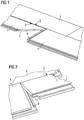
- Fig. 1 shows a perspective fold-down method for locking panels according to the prior art.
- a new panel 1 is angled obliquely with a spring profile edge 2 advanced to a Nutprofilkante 3 of a lying panel 4 a previous row of panels.
- the new panel 1 is pivoted down into the plane of the assembled panels, wherein in the same row of panels an identical panel 5 already lies. Due to the pivoting joining movement, the tongue and groove edge lock together.
- the new panel 1 also has a pair of hook profiles, namely a receiving hook (not shown) and a locking hook 6.
- During the pivoting down joining movement of the locking hook 6 of the new panel 1 is like a scissors in the direction of the complementary receiving hook 7 of the identical panel 5 moves. In this case hooks the locking hook 6 with the receiving hook 7 and at the same time with the locking of tongue and groove profile edge is a positive locking of the hook profiles vonstatten.
- Fig. 1 the structure of a floor surface is indicated.
- a new panel is always applied to the left continuously.
- Fig. 2 shows a second example of a known in the art fold-down method for locking panels. It is different from the method of Fig. 1 only in that a new panel must be applied continuously to the right, ie the panel edges, which have the receiving hook or the locking hook are compared to the example of Fig. 1 been swapped.
- Tongue and groove profiles which are suitable for a positive locking by means of the fold-down method, are well known in the art, for example from the WO 97/47834 A1 or off WO 00/63510 ,
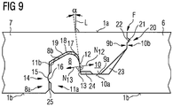
- Fig. 3 illustrates a first embodiment of a panel 1 according to the invention with a panel top 1a and a panel bottom 1b, wherein simplified only one pair of retaining profile of the panel is shown.
- the retaining profile pair shown here has complementary hook profiles, namely a locking hook 6 (top) and a receiving hook 7 (bottom).
- a locking hook 6 top
- a receiving hook 7 bottom
- the receiving hook 6 has a receiving edge 8 directed towards the panel top 1a and a receiving groove 9 which is open towards the panel top.
- the locking hook 7 is provided with a locking edge 10 directed towards the panel bottom 1b and with a locking groove 11 which is open towards the panel bottom 1b.
- the locking hook 7 forms an upper locking surface 13 on an inner side of its locking rim 10 facing the locking groove 11, which cooperates with the lower locking surface 12 of the receiving rim 8 ,
- the inclination of the lower locking surface 12 is selected so that the normal vector N 12 , which is directed from the lower locking surface 12 perpendicular to the outside, the panel top 1a intersects.
- the normal vector N 13 is directed vertically outwards on the upper locking surface 13 , so that this normal vector N 13 intersects the opposite panel underside 1 b.
- the Paneeloberseite 1a and the normal vector N 12 enclose an angle which is as large as the above-mentioned angle ⁇ (changing angle). Applies, The same applies to the underside of the panel, which includes an equal angle (change angle) with the normal vector N 13 .
- a lower catch 14 is provided.
- This comprises on the receiving hook 7, a first locking means in the form of a protruding latching projection 15.
- the latching projection 15 is arranged on an outer side 8a of the receiving edge 8.
- a second latching means in the form of a latching recess 16 is provided on the locking hook 7.
- the detent recess 16 is arranged on a recessed groove flank 11 a of the locking groove 11.
- a portion 8b of the top of the receiving edge 8 has a downward slope, namely falling in the direction of the outside 8a of the receiving edge.
- Matching is on the locking hook 7, a portion 11b of the groove bottom of the locking groove 11 adapted in a complementary manner to the inclination of the portion 8b of the top of the receiving edge 8.
- the inclined sections 8b and 11b of receiving edge top side and Arretiernut ground aligned parallel to each other.
- a transition from the upper side 8 b of the receiving edge 8 to the lower locking surface 12 is provided on the receiving hook 6.
- the transition is formed as a curvature 17.
- the curvature 17 is a radius in the present example.
- a transition with a curvature 18 between the portion 11 b of the groove bottom of the locking groove 11 and the upper locking surface 13 is provided on the locking hook 7.
- the curvature 17 on the receiving edge provides an edge protection and a guide surface.
- the edge protection is stronger than the protective effect a phase which is the same Has width and height, as the curvature 17.
- the curvature 18 forms a throat. It has a radius in the present example and serves the stability in the transition region from the upper locking surface 13 to the groove bottom of the locking groove eleventh
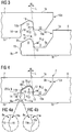
- Fig. 4 are the hook profiles made Fig. 3 shown in the locked state.
- the lower catch 14 counteracts a height offset of the two panel tops 1a, ie a movement apart of the panel edges perpendicular to the panel surface is counteracted.
- a closed joint F also forms in the horizontal direction on the panel surface 1a.
- An outer side 10b of the arresting edge 10 is in contact with a recessed groove flank 9b of the receiving groove 9 in this joint.
- a gap 19 is present between the inclined portion 11b of the groove bottom of the locking groove and the inclined portion 8b of the top of the receiving edge 8. This favors it to avoid a height offset at the joint F of the panel top 1a.
- the gap 19 provides a certain compliance of the locking hook 7. It has a place with its smallest thickness, which is located where the locking groove 11 is the lowest. The yield obtained by this can be used because the gap 19 creates space in which a deformation can take place.
- Fig. 4a shows a detail that enlarges a section that is in Fig. 4 with IVa is noted.
- the locking projection 15 is provided on the receiving hook 6, namely on the outer side 8a of the receiving edge 8.
- the locking recess is provided on the locking hook 7 and there on a set back Nut flank 11a of the locking groove 11th
- a latching recess 15a is arranged on the receiving hook 6, specifically on the outer side 8a of the receiving edge 8.
- a latching projection 16a is then provided on the locking hook 7, namely provided on its recessed groove flank 11a of the locking groove 11.
- FIG. 5 Another embodiment proposes a panel with special hook profiles Fig. 5 in front. This goes from the embodiment of FIGS. 3 and 4 out. From this it differs by an additional upper latching 20.
- the upper latch 20 has on the locking hook 7, a first locking means in the form of a latching projection 21, which is arranged on the outer side 10b of the Arretierrands 10. It acts together with a corresponding second locking means on the receiving hook 6, which is provided on the set-back groove flank 9b of the receiving groove 9.
- the second latching means forms a latching recess 22, as best in the cutout according to Fig. 5a can be seen.
- Fig. 5a magnifies the detail that is in Fig. 5 with Va is designated.
- a latching recess 21 a is arranged on the locking hook, namely on the outside of the arresting edge 10.
- a latching projection 22a is provided on the receiving hook and indeed on the recessed groove flank 9b of the receiving groove.
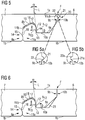
- Fig. 6 shows hook profiles, starting from the FIGS. 3 and 4 Have a change and that in the illustrated locked state of the hook profiles a clearance 23 is formed, which extends between the groove bottom 9a of the receiving groove 9 of the receiving hook 6 and a Bottom 10a of the locking edge 10 of the locking hook 7 extends.
- the free space 23 extends to the outside 10b of the arresting edge 10 or up to the recessed groove flank 9b of the receiving groove 9 zoom.
- the clearance 23 may receive dirt particles or other loose particles. In the case of wood-based panels, for example, particles can detach from the edge of the panel. Detached should not get between the joining surfaces of the hook profiles and settle there, otherwise they hinder a correct position locking the hook profiles.
- the in Fig. 6 proposed space 23 formed gap-shaped.
- the gap-shaped clearance 23 continues towards the bottom of the groove 9a and in this way creates the desired space for receiving unwanted particles.
- Fig. 7 shows hook profiles, which also starting from the FIGS. 3 and 4 have a change in such a way that again in the locked state of the hook profiles a clearance 24 is formed, which extends between the groove bottom 9a of the receiving groove 9 of the receiving hook 6 and a bottom 10a of the Arretierrands 10 of the locking hook 7.
- the free space 24 extends as far as the lower locking surface 12 of the receiving hook 6 or up to the upper locking surface 13 of the locking hook 7 zoom.
- the bottom 10 a of the Arretierrands 10 is provided with a flat shoulder 24 a, which projects from the bottom 10 a of the Arretierrands 10.
- the space 24 can also absorb dirt particles or other loose particles and record in panels of wood materials any detached wood particles that would otherwise set between the joining surfaces of the hook profiles and would hinder a positionally correct locking the hook profiles.
- the remaining portion of the bottom 10a is in the locked state with the groove bottom 9a of the receiving groove 9 in contact and thereby supported.
- Fig. 8 also shows hook profiles, by the FIGS. 3 and 4 out. Compared to these figures, only the lower catch 14 has been modified. According to Fig. 8 the locking projection 15 of the receiving hook 6 protrudes further from the outer side 8a of the receiving edge 8 than in FIG Fig. 4 , The depth of the detent recess 16 is opposite Fig. 4 unchanged. This creates a gap 25 between the outside 8a and the set-back groove flank 11a of the locking groove 11 of the locking hook 7. The gap 25 improves the latchability of the lower catch 14th
- FIG. 8a the lower catch 14 is enlarged as a section.
- An alternative to Fig. 8a shows the clipping according to Fig. 8b , Thereafter, the position of locking recess and locking projection is reversed.
- a detent recess 15a is now arranged on the receiving hook 6 and that on the outer side 8a of the receiving edge 8.
- a latching projection 16a is provided for this purpose on the locking hook 7 on its recessed groove flank 11a of the locking groove 11.
- FIG. 9 Another embodiment of hook profiles of the panel is in Fig. 9 shown. This too is based on the FIGS. 3 and 4 and also integrates all the changes that are made in the examples of Fig. 5, Fig. 6 . FIGS. 7 and 8 were proposed.
Landscapes
- Engineering & Computer Science (AREA)
- Architecture (AREA)
- Civil Engineering (AREA)
- Structural Engineering (AREA)
- Life Sciences & Earth Sciences (AREA)
- Wood Science & Technology (AREA)
- Floor Finish (AREA)
- Finishing Walls (AREA)
- Connection Of Plates (AREA)
- Load-Engaging Elements For Cranes (AREA)
- Hooks, Suction Cups, And Attachment By Adhesive Means (AREA)
- Joining Of Building Structures In Genera (AREA)
- Vehicle Step Arrangements And Article Storage (AREA)
- Compositions Of Macromolecular Compounds (AREA)
Priority Applications (8)
| Application Number | Priority Date | Filing Date | Title |
|---|---|---|---|
| EP18202881.1A EP3467233B1 (fr) | 2014-12-08 | 2015-12-07 | Panneau de plancher avec systeme de verrouillage mechanique |
| PT182028811T PT3467233T (pt) | 2014-12-08 | 2015-12-07 | Painel de pavimento com um sistema de bloqueio mecânico |
| SI201531305T SI3467233T1 (sl) | 2014-12-08 | 2015-12-07 | Talna panelna plošča z mehanskim zapornim sistemom |
| PL18202881T PL3467233T3 (pl) | 2014-12-08 | 2015-12-07 | Panel podłogowy z mechanicznym systemem blokowania |
| SM20200484T SMT202000484T1 (it) | 2014-12-08 | 2015-12-07 | Pannello con sistema di chiusura meccanico |
| RS20200942A RS60778B1 (sr) | 2014-12-08 | 2015-12-07 | Podni panel sa mehaničkim sistemom za zaključano spajanje |
| HRP20201234TT HRP20201234T1 (hr) | 2014-12-08 | 2020-08-06 | Podni panel sa mehaničkim sistemom za zaključano spajanje |
| CY20201100737T CY1123178T1 (el) | 2014-12-08 | 2020-08-06 | Πλακα δαπεδου με μηχανικο συστημα μανδαλωσης |
Applications Claiming Priority (4)
| Application Number | Priority Date | Filing Date | Title |
|---|---|---|---|
| EP14196822.2A EP3031998B1 (fr) | 2014-12-08 | 2014-12-08 | Panneau avec une mécanisme de verrouillage mécanique en forme de crochet |
| EP15804853.8A EP3230534B1 (fr) | 2014-12-08 | 2015-12-07 | Panneau avec une mécanisme de verrouillage mécanique en de forme de crochet |
| PCT/EP2015/078854 WO2016091819A1 (fr) | 2014-12-08 | 2015-12-07 | Panneau avec un système de verrouillage en forme de crochet |
| EP18202881.1A EP3467233B1 (fr) | 2014-12-08 | 2015-12-07 | Panneau de plancher avec systeme de verrouillage mechanique |
Related Parent Applications (2)
| Application Number | Title | Priority Date | Filing Date |
|---|---|---|---|
| EP15804853.8A Division EP3230534B1 (fr) | 2014-12-08 | 2015-12-07 | Panneau avec une mécanisme de verrouillage mécanique en de forme de crochet |
| EP15804853.8A Division-Into EP3230534B1 (fr) | 2014-12-08 | 2015-12-07 | Panneau avec une mécanisme de verrouillage mécanique en de forme de crochet |
Publications (2)
| Publication Number | Publication Date |
|---|---|
| EP3467233A1 true EP3467233A1 (fr) | 2019-04-10 |
| EP3467233B1 EP3467233B1 (fr) | 2020-06-17 |
Family
ID=52013932
Family Applications (6)
| Application Number | Title | Priority Date | Filing Date |
|---|---|---|---|
| EP14196822.2A Active EP3031998B1 (fr) | 2014-12-08 | 2014-12-08 | Panneau avec une mécanisme de verrouillage mécanique en forme de crochet |
| EP15804853.8A Active EP3230534B1 (fr) | 2014-12-08 | 2015-12-07 | Panneau avec une mécanisme de verrouillage mécanique en de forme de crochet |
| EP24167945.5A Pending EP4372181A3 (fr) | 2014-12-08 | 2015-12-07 | Panneau |
| EP21206764.9A Active EP3981931B1 (fr) | 2014-12-08 | 2015-12-07 | Panneau avec système de verrouillage en forme de crochet |
| EP20167421.5A Active EP3705659B1 (fr) | 2014-12-08 | 2015-12-07 | Panneau avec une mécanisme de verrouillage mécanique en de forme de crochet |
| EP18202881.1A Active EP3467233B1 (fr) | 2014-12-08 | 2015-12-07 | Panneau de plancher avec systeme de verrouillage mechanique |
Family Applications Before (5)
| Application Number | Title | Priority Date | Filing Date |
|---|---|---|---|
| EP14196822.2A Active EP3031998B1 (fr) | 2014-12-08 | 2014-12-08 | Panneau avec une mécanisme de verrouillage mécanique en forme de crochet |
| EP15804853.8A Active EP3230534B1 (fr) | 2014-12-08 | 2015-12-07 | Panneau avec une mécanisme de verrouillage mécanique en de forme de crochet |
| EP24167945.5A Pending EP4372181A3 (fr) | 2014-12-08 | 2015-12-07 | Panneau |
| EP21206764.9A Active EP3981931B1 (fr) | 2014-12-08 | 2015-12-07 | Panneau avec système de verrouillage en forme de crochet |
| EP20167421.5A Active EP3705659B1 (fr) | 2014-12-08 | 2015-12-07 | Panneau avec une mécanisme de verrouillage mécanique en de forme de crochet |
Country Status (26)
| Country | Link |
|---|---|
| US (4) | US10738477B2 (fr) |
| EP (6) | EP3031998B1 (fr) |
| JP (2) | JP6854761B2 (fr) |
| KR (1) | KR102493452B1 (fr) |
| CN (3) | CN111877676A (fr) |
| AT (1) | AT17258U1 (fr) |
| AU (2) | AU2015359590B2 (fr) |
| BR (1) | BR112017012129B1 (fr) |
| CA (2) | CA2970056C (fr) |
| CY (3) | CY1119858T1 (fr) |
| DE (1) | DE202015009670U1 (fr) |
| DK (3) | DK3031998T3 (fr) |
| ES (5) | ES2653662T3 (fr) |
| HR (4) | HRP20211998T1 (fr) |
| HU (3) | HUE037701T2 (fr) |
| LT (3) | LT3031998T (fr) |
| MY (2) | MY183479A (fr) |
| NO (1) | NO3031998T3 (fr) |
| PL (5) | PL3031998T4 (fr) |
| PT (3) | PT3031998T (fr) |
| RS (3) | RS56653B1 (fr) |
| RU (1) | RU2711586C2 (fr) |
| SI (3) | SI3031998T1 (fr) |
| SM (1) | SMT202000484T1 (fr) |
| UA (1) | UA122566C2 (fr) |
| WO (1) | WO2016091819A1 (fr) |
Families Citing this family (72)
| Publication number | Priority date | Publication date | Assignee | Title |
|---|---|---|---|---|
| SE533410C2 (sv) | 2006-07-11 | 2010-09-14 | Vaelinge Innovation Ab | Golvpaneler med mekaniska låssystem med en flexibel och förskjutbar tunga samt tunga därför |
| UA109938C2 (uk) | 2011-05-06 | 2015-10-26 | Механічна фіксуюча система для будівельних панелей | |
| US9725912B2 (en) * | 2011-07-11 | 2017-08-08 | Ceraloc Innovation Ab | Mechanical locking system for floor panels |
| HUE060779T2 (hu) | 2013-06-27 | 2023-04-28 | Vaelinge Innovation Ab | Mechanikus rögzítõrendszerrel ellátott építõpanel |
| US9726210B2 (en) | 2013-09-16 | 2017-08-08 | Valinge Innovation Ab | Assembled product and a method of assembling the product |
| CA2933681C (fr) * | 2014-01-10 | 2021-10-19 | Valinge Innovation Ab | Panneau de meuble |
| US9714672B2 (en) | 2014-01-10 | 2017-07-25 | Valinge Innovation Ab | Panels comprising a mechanical locking device and an assembled product comprising the panels |
| CN106460901B (zh) | 2014-05-09 | 2020-02-04 | 瓦林格创新股份有限公司 | 用于建筑镶板的机械锁定系统 |
| CN107002411B (zh) | 2014-11-27 | 2020-06-16 | 瓦林格创新股份有限公司 | 用于地板镶板的机械锁定系统 |
| BR112017012422B1 (pt) | 2014-12-19 | 2022-11-08 | Vãlinge Innovation Ab | Conjunto de painéis compreendendo um dispositivo de travamento mecânico |
| EP3285620A4 (fr) | 2015-04-21 | 2018-11-14 | Välinge Innovation AB | Panneau à coulisse |
| MY185635A (en) | 2015-04-30 | 2021-05-27 | Valinge Innovation Ab | Panel with a fastening device |
| UA125554C2 (uk) | 2015-09-22 | 2022-04-20 | Велінге Інновейшн Аб | Панелі, що містять механічний фіксуючий пристрій, і зібраний виріб, що містить панелі |
| PL3147135T3 (pl) * | 2015-09-24 | 2021-06-14 | Akzenta Paneele + Profile Gmbh | Sposób wytwarzania dekoracyjnego panelu ściennego lub podłogowego |
| LT3384165T (lt) | 2015-12-03 | 2021-11-10 | Välinge Innovation AB | Plokščių su mechaniniu fiksavimo įrenginiu rinkinys |
| WO2017131574A1 (fr) | 2016-01-26 | 2017-08-03 | Välinge Innovation AB | Panneaux comprenant un dispositif de verrouillage mécanique et produit assemblé comportant les panneaux |
| RU2724688C2 (ru) | 2016-02-04 | 2020-06-25 | Велинге Инновейшн Аб | Набор панелей для собранного изделия |
| CA3011703A1 (fr) | 2016-02-09 | 2017-08-17 | Valinge Innovation Ab | Element et procede de fourniture de rainure de demontage |
| CA3011612A1 (fr) | 2016-02-09 | 2017-08-17 | Valinge Innovation Ab | Ensemble de trois elements en forme de panneau |
| MX2018009631A (es) | 2016-02-15 | 2018-12-17 | Vaelinge Innovation Ab | Un metodo para formar un panel para un producto de mobiliario. |
| CA3040653A1 (fr) | 2016-10-27 | 2018-05-03 | Valinge Innovation Ab | Ensemble de panneaux avec un dispositif de verrouillage mecanique |
| PL3315316T3 (pl) | 2016-10-27 | 2021-06-14 | Akzenta Paneele + Profile Gmbh | Sposób wytwarzania dekorowanego panelu ściennego lub podłogowego |
| EA038797B1 (ru) | 2017-05-15 | 2021-10-20 | Велинге Инновейшн Аб | Набор для механической блокировки цилиндрических частей сборного мебельного изделия |
| NL2019108B1 (en) * | 2017-06-22 | 2019-01-07 | Champion Link Int Corp | Floor panel and method of producing such a floor panel |
| CA3086335A1 (fr) | 2017-12-22 | 2019-06-27 | Valinge Innovation Ab | Ensemble de panneaux, son procede d'assemblage et dispositif de verrouillage pour un produit de mobilier |
| EP3728869B1 (fr) | 2017-12-22 | 2023-01-25 | Välinge Innovation AB | Ensemble de panneaux, leur procédé d'assemblage et dispositif de verrouillage pour un produit de mobilier |
| NO20172047A1 (no) * | 2017-12-24 | 2019-06-25 | Humeneq As | Oppfinnelsen angår en klikkanordning for benkeplate- og andre plateskjøter. |
| NL2020256B1 (en) | 2018-01-09 | 2019-07-15 | Innovations4Flooring Holding N V | Panel |
| HRP20231305T1 (hr) | 2018-03-23 | 2024-02-02 | Välinge Innovation AB | Skup ploča |
| US10590659B2 (en) | 2018-04-05 | 2020-03-17 | 888804 Ontario Limited | Pre-finished insulated panel system for cladding a building |
| CN112262265B (zh) | 2018-04-18 | 2022-12-20 | 瓦林格创新股份有限公司 | 对称榫舌和t形交叉组件 |
| EP3781822B1 (fr) | 2018-04-18 | 2024-08-21 | Välinge Innovation AB | Ensemble de panneaux comprenant un dispositif de verrouillage mécanique |
| WO2019203722A1 (fr) | 2018-04-18 | 2019-10-24 | Välinge Innovation AB | Ensemble de panneaux avec un dispositif de verrouillage mécanique |
| EP3781823B1 (fr) | 2018-04-18 | 2024-04-10 | Välinge Innovation AB | Ensemble de panneaux avec un dispositif de verrouillage mécanique |
| US11614114B2 (en) | 2018-04-19 | 2023-03-28 | Valinge Innovation Ab | Panels for an assembled product |
| NL2020972B1 (en) * | 2018-05-23 | 2019-12-02 | Innovations4Flooring Holding N V | Multi-purpose tile system, tile covering, and tile |
| PL3578384T3 (pl) | 2018-06-05 | 2022-02-28 | Akzenta Paneele + Profile Gmbh | Podłoże na bazie kompozycji tworzyw sztucznych i kompozycji stałych na bazie mineralnej do dekorowanych paneli ściennych lub podłogowych |
| EP4410151B1 (fr) | 2018-08-30 | 2026-04-15 | Välinge Innovation AB | Ensemble de panneaux avec un dispositif de verrouillage mécanique |
| KR102878208B1 (ko) | 2018-08-30 | 2025-10-28 | 뵈린게 이노베이션 에이비이 | 기계적인 잠금 디바이스를 갖는 패널들의 세트 |
| NL2021887B1 (en) * | 2018-10-26 | 2020-05-13 | I4F Licensing Nv | Multi-purpose tile system, tile covering, and tile |
| NL2021884B1 (en) * | 2018-10-26 | 2020-05-13 | I4F Licensing Nv | Panel, in particular a floor panel or wall panel |
| NL2021885B1 (en) * | 2018-10-26 | 2020-05-13 | I4F Licensing Nv | Multi-purpose tile system, tile covering, and tile |
| NL2022114B1 (en) * | 2018-12-03 | 2020-06-30 | I4F Licensing Nv | Decorative panel, and decorative floor covering consisting of said panels |
| AU2019394553B2 (en) | 2018-12-05 | 2025-10-23 | I4F Licensing Nv | Decorative panel, and decorative floor covering consisting of said panels |
| EA202191810A1 (ru) | 2019-01-10 | 2021-10-05 | Велинге Инновейшн Аб | Система разблокирования для панелей |
| EP3918150B1 (fr) * | 2019-01-30 | 2024-12-18 | I4F Licensing Nv | Panneau et revêtement de sol comprenant ledit panneau |
| AU2019426795B2 (en) | 2019-01-30 | 2025-04-24 | I4F Licensing Nv | A flooring panel and a floor covering with such panel |
| WO2020159355A1 (fr) * | 2019-01-30 | 2020-08-06 | Floor Locking Technology B.V. | Panneau et revêtement le comprenant |
| CN109826391B (zh) * | 2019-04-04 | 2024-01-26 | 湖南工业大学 | 一种锁扣式连接件及板材 |
| BE1027299B1 (nl) | 2019-05-22 | 2020-12-22 | Flooring Ind Ltd Sarl | Vloerpaneel voor het vormen van een vloerbekleding |
| EP4025748A1 (fr) * | 2019-09-06 | 2022-07-13 | I4F Licensing Nv | Panneau de plancher et plancher |
| US12325800B2 (en) * | 2019-09-17 | 2025-06-10 | Merck Patent Gmbh | Laser additive |
| EP3798386A1 (fr) * | 2019-09-24 | 2021-03-31 | Välinge Innovation AB | Ensemble de panneaux avec bords verrouillables mécaniquement |
| CA3153635A1 (fr) * | 2019-09-25 | 2021-04-01 | Valinge Innovation Ab | Panneau dote d'un dispositif de verrouillage |
| NL2024193B1 (en) * | 2019-11-08 | 2021-07-20 | I4F Licensing Nv | Decorative panel suitable for assembling a floor, ceiling or wall covering by interconnecting a plurality of said panels with each other, and decorative covering of such interconnected panels |
| NL2024192B1 (en) * | 2019-11-08 | 2021-07-28 | I4F Licensing Nv | Decorative panel, and decorative floor covering consisting of said panels |
| LU101663B1 (en) * | 2020-03-06 | 2021-09-14 | Tarkett Gdl Sa | Set of surface covering planks and method of connecting thereof |
| WO2021225715A1 (fr) | 2020-05-05 | 2021-11-11 | Owens Corning Intellectual Capital, Llc | Panneaux isolants à bords à feuillure emboîtables |
| WO2021245261A1 (fr) * | 2020-06-04 | 2021-12-09 | I4F Licensing Nv | Panneau décoratif et revêtement de sol décoratif constitué de ces panneaux |
| US11702844B2 (en) * | 2020-06-05 | 2023-07-18 | Valinge Innovation Ab | Building panels comprising a locking device |
| CN111719806B (zh) * | 2020-06-19 | 2021-08-24 | 安徽可尔海思塑业有限公司 | 一种减小踩踏噪音的防水地板的生产工艺 |
| KR102188790B1 (ko) * | 2020-07-04 | 2020-12-08 | 윤경식 | 층간소음 방지용 매트 |
| NL2026190B1 (en) * | 2020-07-31 | 2022-04-04 | I4F Licensing Nv | Panel and covering |
| PT4189192T (pt) | 2020-07-31 | 2025-03-10 | I4F Licensing Nv | Painel e revestimento |
| US12195964B2 (en) | 2020-08-24 | 2025-01-14 | Huber Engineered Woods Llc | Tongue-and-groove panel for improved interpanel fit |
| EP3971366A1 (fr) * | 2020-09-17 | 2022-03-23 | Surface Technologies GmbH & Co. KG | Panneau |
| NL2026858B1 (en) * | 2020-11-09 | 2022-06-27 | I4F Licensing Nv | Decorative panel, and covering of such decorative panels |
| CN116888333A (zh) * | 2021-02-03 | 2023-10-13 | 瓦林格创新股份有限公司 | 包括锁定装置的建筑镶板 |
| CN113134887B (zh) * | 2021-03-04 | 2022-06-28 | 象乐宝(福建)新材料科技有限公司 | 一种环保木地板全智能化生产线 |
| CN113134889B (zh) * | 2021-03-04 | 2025-09-05 | 象乐宝(福建)新材料科技有限公司 | 一种防火木地板环保制备系统及方法 |
| BE1029518B1 (nl) * | 2021-06-23 | 2023-01-30 | Flooring Ind Ltd Sarl | Decoratief paneel |
| MX2023015105A (es) * | 2021-06-23 | 2024-01-22 | Flooring Ind Ltd Sarl | Panel decorativo. |
Citations (8)
| Publication number | Priority date | Publication date | Assignee | Title |
|---|---|---|---|---|
| WO1997047834A1 (fr) | 1996-06-11 | 1997-12-18 | Unilin Beheer B.V. | Revetement de sol compose de panneaux de plancher durs et procede de fabrication de ces panneaux de plancher |
| WO2000063510A1 (fr) | 1999-04-20 | 2000-10-26 | Patt S.R.L. | Revetement de plancher constitue de panneaux de plancher et procede d'assemblage correspondant |
| WO2001002670A1 (fr) | 1999-06-30 | 2001-01-11 | Akzenta Paneele + Profile Gmbh | Panneau et dispositif de fixation pour panneaux |
| EP1108529A2 (fr) * | 1999-12-14 | 2001-06-20 | Mannington Mills, Inc. | Planches thermoplastiques et procédé pour leur production |
| WO2010143962A2 (fr) | 2009-06-12 | 2010-12-16 | 4Sight Innovation B.V. | Panneau de plancher et revêtement de plancher consistant en une pluralité de tels panneaux de plancher |
| DE102011086846A1 (de) * | 2011-01-28 | 2012-08-02 | Akzenta Paneele + Profile Gmbh | Paneel |
| WO2014084787A1 (fr) * | 2012-11-28 | 2014-06-05 | Ceraloc Innovation Ab | Procédé de production d'un panneau de bâtiment par impression numérique |
| EP2757129A1 (fr) * | 2013-01-18 | 2014-07-23 | Akzenta Paneele + Profile GmbH | Panneau de décoration avec plaque de support modifiée par poudre élastomère |
Family Cites Families (72)
| Publication number | Priority date | Publication date | Assignee | Title |
|---|---|---|---|---|
| GB816243A (en) | 1956-10-16 | 1959-07-08 | Seby Carl J | Improvements in or relating to elements for forming floor covering or the like |
| SE515210C2 (sv) | 2000-04-10 | 2001-06-25 | Valinge Aluminium Ab | Låssystem för hopfogning av golvskivor samt golvskivor försedda med sådana låssystem och golv bildat av sådana golvskivor |
| US3921312A (en) | 1974-11-26 | 1975-11-25 | Craig Fuller | Educational construction |
| FR2416988A1 (fr) | 1978-02-08 | 1979-09-07 | Marty Parquets | Nouveau profil d'assemblage de lambris |
| US4426820A (en) | 1979-04-24 | 1984-01-24 | Heinz Terbrack | Panel for a composite surface and a method of assembling same |
| US4696132A (en) | 1985-04-22 | 1987-09-29 | Leblanc J T | Foldable shelter system and method of construction |
| EP0214643B1 (fr) | 1985-09-09 | 1991-04-03 | Wolfgang Rosner | Joint de rainure et languette endtre deux panneaux de bois voisins |
| JPH0540190Y2 (fr) | 1987-10-29 | 1993-10-13 | ||
| CA1292112C (fr) | 1988-03-16 | 1991-11-19 | Alexander V. Parasin | Profil de languette et rainure |
| JPH01300979A (ja) | 1988-05-30 | 1989-12-05 | Tokyo Electric Co Ltd | 電気かみそり |
| JPH0324538U (fr) | 1989-07-13 | 1991-03-13 | ||
| US5182892A (en) | 1991-08-15 | 1993-02-02 | Louisiana-Pacific Corporation | Tongue and groove board product |
| JP2693093B2 (ja) | 1992-10-05 | 1997-12-17 | カウンシル・オブ・フォーレスト・インダストリーズ・オブ・ブリティッシュ・コロンビア | 突起及び溝を具備するパネル |
| US5274979A (en) | 1992-12-22 | 1994-01-04 | Tsai Jui Hsing | Insulating plate unit |
| JP3461569B2 (ja) | 1994-05-02 | 2003-10-27 | 大建工業株式会社 | 床 材 |
| JP3631798B2 (ja) | 1995-03-30 | 2005-03-23 | 大建工業株式会社 | 建築用床板 |
| FR2746127B1 (fr) | 1996-03-13 | 1998-05-07 | Profil d'assemblage pour lames de parquet | |
| JPH10979A (ja) | 1996-06-17 | 1998-01-06 | Kobe Steel Ltd | 応急道路敷設・撤収車両 |
| US6131355A (en) | 1996-11-21 | 2000-10-17 | Crane Plastics Company Limited Partnership | Deck plank |
| JPH1144084A (ja) | 1997-07-30 | 1999-02-16 | Natl House Ind Co Ltd | 床板材の敷設構造 |
| BE1012141A6 (nl) | 1998-07-24 | 2000-05-02 | Unilin Beheer Bv | Vloerbekleding, vloerpaneel daarvoor en werkwijze voor het realiseren van dergelijk vloerpaneel. |
| US6098365A (en) | 1998-11-19 | 2000-08-08 | Apa - The Engineered Wood Association | Radius tongue and groove profile |
| CN2361725Y (zh) | 1999-02-10 | 2000-02-02 | 宁波保税区中欧实业有限公司 | 一种压装锁扣式强化复合地板 |
| SE517478C2 (sv) | 1999-04-30 | 2002-06-11 | Valinge Aluminium Ab | Låssystem för mekanisk hofogning av golvskivor, golvskiva försedd med låssystemet samt metod för framställning av mekaniskt hopfogningsbara golvskivor |
| DE29911462U1 (de) | 1999-07-02 | 1999-11-18 | Akzenta Paneele & Profile Gmbh | Befestigungssystem für Paneele |
| DE19933343A1 (de) | 1999-07-16 | 2001-02-01 | Ledermann & Co | Verfahren zum Verbinden von Platten und Verbindungsanordnung |
| US6939496B2 (en) | 1999-12-20 | 2005-09-06 | Psa Composites, Llc | Method and apparatus for forming composite material and composite material therefrom |
| US7337588B1 (en) | 1999-12-27 | 2008-03-04 | Maik Moebus | Panel with slip-on profile |
| DE10001076C1 (de) | 2000-01-13 | 2001-10-04 | Huelsta Werke Huels Kg | Paneelelement |
| SE517183C2 (sv) * | 2000-01-24 | 2002-04-23 | Valinge Aluminium Ab | Låssystem för mekanisk hopfogning av golvskivor, golvskiva försedd med låssystemet och metod för framställning av sådana golvskivor |
| SE518184C2 (sv) | 2000-03-31 | 2002-09-03 | Perstorp Flooring Ab | Golvbeläggningsmaterial innefattande skivformiga golvelement vilka sammanfogas med hjälp av sammankopplingsorgan |
| DE20008708U1 (de) * | 2000-05-16 | 2000-09-14 | Kronospan Technical Co. Ltd., Nikosia | Paneele mit Kupplungsmitteln |
| FR2826391A1 (fr) | 2001-06-20 | 2002-12-27 | Arnaud Becker | Dispositif d'assemblage des bords de panneaux, lattes ou lambris |
| DE20122778U1 (de) | 2001-08-10 | 2007-10-25 | Akzenta Paneele + Profile Gmbh | Paneel sowie Befestigungssystem für Paneele |
| US20030093964A1 (en) | 2001-10-16 | 2003-05-22 | Bushey Richard D. | Floor grid system |
| DE10231921A1 (de) | 2002-06-28 | 2004-01-22 | E.F.P. Floor Products Fussböden GmbH | Paneel eines Fußbodensystems, insbesondere eines Laminatfußbodens |
| US7617651B2 (en) | 2002-11-12 | 2009-11-17 | Kronotec Ag | Floor panel |
| DE20219110U1 (de) | 2002-12-09 | 2003-03-13 | Kronospan Technical Company Ltd., Engomi, Nikosia | Paneele mit Kabelkanal |
| US7845140B2 (en) | 2003-03-06 | 2010-12-07 | Valinge Innovation Ab | Flooring and method for installation and manufacturing thereof |
| DE10313112B4 (de) * | 2003-03-24 | 2007-05-03 | Fritz Egger Gmbh & Co. | Belag mit einer Mehrzahl von Paneelen, insbesondere Fußbodenbelag, sowie Verfahren zum Verlegen von Paneelen |
| KR100566083B1 (ko) | 2003-08-07 | 2006-03-30 | 주식회사 한솔홈데코 | 조립식 바닥재 |
| US20050183370A1 (en) | 2004-02-06 | 2005-08-25 | Cripps Milo F. | Interlocking Tile |
| US20060156666A1 (en) | 2005-01-20 | 2006-07-20 | Caufield Francis J | Synthetic boards for exterior water-resistant applications |
| US8215078B2 (en) | 2005-02-15 | 2012-07-10 | Välinge Innovation Belgium BVBA | Building panel with compressed edges and method of making same |
| DE202005004537U1 (de) | 2005-03-17 | 2005-06-16 | Schulte, Johannes | Paneele für Fußboden-, Wand- oder Deckenbeläge |
| US20060260253A1 (en) | 2005-05-23 | 2006-11-23 | Quality Craft Ltd. | Laminate flooring panel bevel and method of manufacturing same |
| DE102005028072B4 (de) | 2005-06-16 | 2010-12-30 | Akzenta Paneele + Profile Gmbh | Fußbodenpaneel |
| US20070130872A1 (en) | 2005-12-08 | 2007-06-14 | Goodwin Milton W | Wide width lock and fold laminate |
| DE102006011887A1 (de) | 2006-01-13 | 2007-07-19 | Akzenta Paneele + Profile Gmbh | Sperrelement, Paneel mit separatem Sperrelement, Verfahren zur Installation eines Paneelbelags aus Paneelen mit Sperrelementen sowie Verfahren und Vorrichtung zur Vormontage eines Sperrelements an einem Paneel |
| DK2009197T3 (en) | 2006-04-14 | 2016-06-13 | Yekalon Ind Inc | Floor block, floor system and laying method therefore |
| SE533410C2 (sv) * | 2006-07-11 | 2010-09-14 | Vaelinge Innovation Ab | Golvpaneler med mekaniska låssystem med en flexibel och förskjutbar tunga samt tunga därför |
| SE532607C2 (sv) * | 2006-11-15 | 2010-03-02 | Vaelinge Innovation Ab | Mekanisk låsning av golvpaneler med vertikal vikning |
| US8689512B2 (en) | 2006-11-15 | 2014-04-08 | Valinge Innovation Ab | Mechanical locking of floor panels with vertical folding |
| KR101468444B1 (ko) * | 2006-11-15 | 2014-12-03 | 뵈린게 이노베이션 에이비이 | 수직 폴딩을 구비하는 마루 패널들의 기계적인 잠금 |
| CN101096440B (zh) * | 2007-05-22 | 2010-06-09 | 深圳职业技术学院 | 一种sebs热塑性弹性体地板及其制造方法 |
| CN101372545A (zh) * | 2007-08-23 | 2009-02-25 | 青岛同飞管业有限公司 | 一种新型木塑地板及其生产方法 |
| DE102007042840B4 (de) * | 2007-09-10 | 2010-04-22 | Flooring Technologies Ltd. | Paneel, insbesondere Bodenpaneel |
| DE202008010555U1 (de) | 2008-08-08 | 2009-12-17 | Akzenta Paneele + Profile Gmbh | Kunststoffpaneel mit Hakenprofil |
| DE202008011589U1 (de) | 2008-09-01 | 2008-11-27 | Akzenta Paneele + Profile Gmbh | Fußbodenpaneel aus Kunststoff mit mechanischen Verriegelungskanten |
| CN101492950B (zh) | 2008-09-10 | 2011-01-12 | 滁州扬子木业有限公司 | 带有锁合装置的地板 |
| KR100947849B1 (ko) | 2008-11-11 | 2010-03-18 | 동화자연마루(주) | 텅 앤드 텅 조인트구조를 갖는 마루판 |
| US8365499B2 (en) | 2009-09-04 | 2013-02-05 | Valinge Innovation Ab | Resilient floor |
| BR112012018285B1 (pt) * | 2010-02-04 | 2020-02-18 | Välinge Innovation AB | Conjunto de painéis de piso |
| EP2588685B1 (fr) * | 2010-06-30 | 2020-08-05 | Kreafin Group SA | Panneau avec moyens d'accouplement améliorés |
| CN101942159B (zh) * | 2010-09-15 | 2012-09-12 | 于德胜 | 一种石塑仿木地板及其加工方法 |
| DE102010063976B4 (de) | 2010-12-22 | 2013-01-17 | Akzenta Paneele + Profile Gmbh | Paneel |
| SG193535A1 (en) * | 2011-03-18 | 2013-10-30 | Inotec Internat Pty Ltd | Vertical joint system and associated surface covering system |
| DE102011104718B4 (de) * | 2011-06-06 | 2016-08-04 | Fritz Egger Gmbh & Co. Og | Fußbodenpaneel mit einer einen Sperrriegel afweisenden Seitenkante |
| DE102011121348A1 (de) * | 2011-12-19 | 2013-06-20 | Fritz Egger Gmbh & Co. Og | Paneel eines Fußbodenbelags mit einer entlang einer Seitenkante geneigten Verriegelungsfläche |
| BE1022209B1 (nl) * | 2012-01-12 | 2016-03-01 | I.V.C. N.V. | Vloerpaneel |
| US10316526B2 (en) * | 2014-08-29 | 2019-06-11 | Valinge Innovation Ab | Vertical joint system for a surface covering panel |
| CN106117081B (zh) | 2016-06-24 | 2018-03-27 | 嘉兴学院 | 一种含α‑H的炔基亚胺化合物的制备方法 |
-
2014
- 2014-12-08 NO NO14196822A patent/NO3031998T3/no unknown
- 2014-12-08 RS RS20171294A patent/RS56653B1/sr unknown
- 2014-12-08 PT PT141968222T patent/PT3031998T/pt unknown
- 2014-12-08 DK DK14196822.2T patent/DK3031998T3/en active
- 2014-12-08 EP EP14196822.2A patent/EP3031998B1/fr active Active
- 2014-12-08 SI SI201430524T patent/SI3031998T1/en unknown
- 2014-12-08 LT LTEP14196822.2T patent/LT3031998T/lt unknown
- 2014-12-08 ES ES14196822.2T patent/ES2653662T3/es active Active
- 2014-12-08 HU HUE14196822A patent/HUE037701T2/hu unknown
- 2014-12-08 PL PL14196822T patent/PL3031998T4/pl unknown
-
2015
- 2015-12-07 RU RU2017124001A patent/RU2711586C2/ru active
- 2015-12-07 LT LTEP15804853.8T patent/LT3230534T/lt unknown
- 2015-12-07 MY MYPI2017702122A patent/MY183479A/en unknown
- 2015-12-07 SI SI201531305T patent/SI3467233T1/sl unknown
- 2015-12-07 AT ATGM76/2020U patent/AT17258U1/de not_active IP Right Cessation
- 2015-12-07 HR HRP20211998TT patent/HRP20211998T1/hr unknown
- 2015-12-07 ES ES15804853T patent/ES2800165T3/es active Active
- 2015-12-07 ES ES18202881T patent/ES2811224T3/es active Active
- 2015-12-07 WO PCT/EP2015/078854 patent/WO2016091819A1/fr not_active Ceased
- 2015-12-07 DE DE202015009670.0U patent/DE202015009670U1/de not_active Expired - Lifetime
- 2015-12-07 PL PL21206764.9T patent/PL3981931T3/pl unknown
- 2015-12-07 KR KR1020177019115A patent/KR102493452B1/ko active Active
- 2015-12-07 PT PT182028811T patent/PT3467233T/pt unknown
- 2015-12-07 EP EP15804853.8A patent/EP3230534B1/fr active Active
- 2015-12-07 CN CN202010466692.4A patent/CN111877676A/zh active Pending
- 2015-12-07 PL PL15804853T patent/PL3230534T4/pl unknown
- 2015-12-07 CN CN202010467251.6A patent/CN111877677A/zh active Pending
- 2015-12-07 EP EP24167945.5A patent/EP4372181A3/fr active Pending
- 2015-12-07 SI SI201531241T patent/SI3230534T1/sl unknown
- 2015-12-07 PL PL20167421T patent/PL3705659T3/pl unknown
- 2015-12-07 PL PL18202881T patent/PL3467233T3/pl unknown
- 2015-12-07 ES ES21206764T patent/ES2986861T3/es active Active
- 2015-12-07 BR BR112017012129-8A patent/BR112017012129B1/pt active IP Right Grant
- 2015-12-07 EP EP21206764.9A patent/EP3981931B1/fr active Active
- 2015-12-07 CN CN201580073627.2A patent/CN108026728B/zh active Active
- 2015-12-07 SM SM20200484T patent/SMT202000484T1/it unknown
- 2015-12-07 EP EP20167421.5A patent/EP3705659B1/fr active Active
- 2015-12-07 AU AU2015359590A patent/AU2015359590B2/en active Active
- 2015-12-07 JP JP2017530615A patent/JP6854761B2/ja active Active
- 2015-12-07 RS RS20200942A patent/RS60778B1/sr unknown
- 2015-12-07 ES ES20167421T patent/ES2902444T3/es active Active
- 2015-12-07 HU HUE18202881A patent/HUE050129T2/hu unknown
- 2015-12-07 US US15/533,811 patent/US10738477B2/en active Active
- 2015-12-07 RS RS20200708A patent/RS60457B1/sr unknown
- 2015-12-07 PT PT158048538T patent/PT3230534T/pt unknown
- 2015-12-07 CA CA2970056A patent/CA2970056C/fr active Active
- 2015-12-07 LT LTEP18202881.1T patent/LT3467233T/lt unknown
- 2015-12-07 CA CA3184360A patent/CA3184360C/fr active Active
- 2015-12-07 MY MYPI2021000884A patent/MY202786A/en unknown
- 2015-12-07 HU HUE15804853A patent/HUE051009T2/hu unknown
- 2015-12-07 DK DK15804853.8T patent/DK3230534T3/da active
- 2015-12-07 DK DK18202881.1T patent/DK3467233T3/da active
- 2015-12-07 HR HRP20200972TT patent/HRP20200972T1/hr unknown
- 2015-12-07 EP EP18202881.1A patent/EP3467233B1/fr active Active
- 2015-12-07 UA UAA201707127A patent/UA122566C2/uk unknown
-
2017
- 2017-12-18 CY CY20171101322T patent/CY1119858T1/el unknown
- 2017-12-18 HR HRP20171956TT patent/HRP20171956T1/hr unknown
-
2020
- 2020-06-25 CY CY20201100592T patent/CY1123082T1/el unknown
- 2020-07-28 US US16/940,546 patent/US11319712B2/en active Active
- 2020-08-06 CY CY20201100737T patent/CY1123178T1/el unknown
- 2020-08-06 HR HRP20201234TT patent/HRP20201234T1/hr unknown
- 2020-12-24 JP JP2020215391A patent/JP7063978B2/ja active Active
-
2021
- 2021-02-18 AU AU2021201051A patent/AU2021201051B2/en active Active
-
2022
- 2022-04-14 US US17/720,424 patent/US11913237B2/en active Active
-
2023
- 2023-12-12 US US18/536,632 patent/US12352053B2/en active Active
Patent Citations (8)
| Publication number | Priority date | Publication date | Assignee | Title |
|---|---|---|---|---|
| WO1997047834A1 (fr) | 1996-06-11 | 1997-12-18 | Unilin Beheer B.V. | Revetement de sol compose de panneaux de plancher durs et procede de fabrication de ces panneaux de plancher |
| WO2000063510A1 (fr) | 1999-04-20 | 2000-10-26 | Patt S.R.L. | Revetement de plancher constitue de panneaux de plancher et procede d'assemblage correspondant |
| WO2001002670A1 (fr) | 1999-06-30 | 2001-01-11 | Akzenta Paneele + Profile Gmbh | Panneau et dispositif de fixation pour panneaux |
| EP1108529A2 (fr) * | 1999-12-14 | 2001-06-20 | Mannington Mills, Inc. | Planches thermoplastiques et procédé pour leur production |
| WO2010143962A2 (fr) | 2009-06-12 | 2010-12-16 | 4Sight Innovation B.V. | Panneau de plancher et revêtement de plancher consistant en une pluralité de tels panneaux de plancher |
| DE102011086846A1 (de) * | 2011-01-28 | 2012-08-02 | Akzenta Paneele + Profile Gmbh | Paneel |
| WO2014084787A1 (fr) * | 2012-11-28 | 2014-06-05 | Ceraloc Innovation Ab | Procédé de production d'un panneau de bâtiment par impression numérique |
| EP2757129A1 (fr) * | 2013-01-18 | 2014-07-23 | Akzenta Paneele + Profile GmbH | Panneau de décoration avec plaque de support modifiée par poudre élastomère |
Also Published As
Similar Documents
| Publication | Publication Date | Title |
|---|---|---|
| EP3705659B1 (fr) | Panneau avec une mécanisme de verrouillage mécanique en de forme de crochet | |
| EP3333339B1 (fr) | Panneau | |
| DE102014106492A1 (de) | Paneel | |
| EP3121348B1 (fr) | Panneau | |
| DE202016102034U1 (de) | Fußbodenpaneel zur Bildung eines Fußbodenbelags | |
| EP2668350B1 (fr) | Panneau | |
| DE60010752T2 (de) | Verfahren zur herstellung von einem verbundwerkstoff und verbundwerkstoff daraus | |
| DE202019005464U1 (de) | Paneel, insbesondere ein Bodenpaneel oder Wandpaneel | |
| DE112014001304T5 (de) | Glaspartikel- und Faser- Polymerkomposit bzw. -gemisch | |
| WO2010023042A1 (fr) | Panneau de plancher en matière plastique, comportant des arêtes de verrouillage mécaniques | |
| EP3325736B1 (fr) | Panneau pourvu de chanfreins sur les faces superieures de deux cotés opposés | |
| EP2694300A1 (fr) | Revêtement de sol et procédé de fabrication de ce revêtement | |
| EP2180116B1 (fr) | Procédé de fabrication des panneaux de revêtement de sol en matière plastique élastique | |
| DE202015009842U1 (de) | Paneel | |
| DE102011052711A1 (de) | Belag aus mechanisch miteinander verbindbaren Paneelen | |
| DE202010017178U1 (de) | Paneel |
Legal Events
| Date | Code | Title | Description |
|---|---|---|---|
| PUAI | Public reference made under article 153(3) epc to a published international application that has entered the european phase |
Free format text: ORIGINAL CODE: 0009012 |
|
| STAA | Information on the status of an ep patent application or granted ep patent |
Free format text: STATUS: THE APPLICATION HAS BEEN PUBLISHED |
|
| AC | Divisional application: reference to earlier application |
Ref document number: 3230534 Country of ref document: EP Kind code of ref document: P |
|
| AK | Designated contracting states |
Kind code of ref document: A1 Designated state(s): AL AT BE BG CH CY CZ DE DK EE ES FI FR GB GR HR HU IE IS IT LI LT LU LV MC MK MT NL NO PL PT RO RS SE SI SK SM TR |
|
| STAA | Information on the status of an ep patent application or granted ep patent |
Free format text: STATUS: REQUEST FOR EXAMINATION WAS MADE |
|
| 17P | Request for examination filed |
Effective date: 20191010 |
|
| RBV | Designated contracting states (corrected) |
Designated state(s): AL AT BE BG CH CY CZ DE DK EE ES FI FR GB GR HR HU IE IS IT LI LT LU LV MC MK MT NL NO PL PT RO RS SE SI SK SM TR |
|
| GRAP | Despatch of communication of intention to grant a patent |
Free format text: ORIGINAL CODE: EPIDOSNIGR1 |
|
| STAA | Information on the status of an ep patent application or granted ep patent |
Free format text: STATUS: GRANT OF PATENT IS INTENDED |
|
| RIC1 | Information provided on ipc code assigned before grant |
Ipc: E04F 15/10 20060101ALI20200113BHEP Ipc: E04F 15/02 20060101AFI20200113BHEP Ipc: E04F 15/04 20060101ALI20200113BHEP |
|
| INTG | Intention to grant announced |
Effective date: 20200131 |
|
| RAP1 | Party data changed (applicant data changed or rights of an application transferred) |
Owner name: I4F LICENSING NV |
|
| GRAS | Grant fee paid |
Free format text: ORIGINAL CODE: EPIDOSNIGR3 |
|
| GRAA | (expected) grant |
Free format text: ORIGINAL CODE: 0009210 |
|
| STAA | Information on the status of an ep patent application or granted ep patent |
Free format text: STATUS: THE PATENT HAS BEEN GRANTED |
|
| AC | Divisional application: reference to earlier application |
Ref document number: 3230534 Country of ref document: EP Kind code of ref document: P |
|
| AK | Designated contracting states |
Kind code of ref document: B1 Designated state(s): AL AT BE BG CH CY CZ DE DK EE ES FI FR GB GR HR HU IE IS IT LI LT LU LV MC MK MT NL NO PL PT RO RS SE SI SK SM TR |
|
| REG | Reference to a national code |
Ref country code: GB Ref legal event code: FG4D Free format text: NOT ENGLISH |
|
| REG | Reference to a national code |
Ref country code: CH Ref legal event code: EP |
|
| REG | Reference to a national code |
Ref country code: IE Ref legal event code: FG4D Free format text: LANGUAGE OF EP DOCUMENT: GERMAN |
|
| REG | Reference to a national code |
Ref country code: DE Ref legal event code: R096 Ref document number: 502015012838 Country of ref document: DE |
|
| REG | Reference to a national code |
Ref country code: AT Ref legal event code: REF Ref document number: 1281469 Country of ref document: AT Kind code of ref document: T Effective date: 20200715 |
|
| REG | Reference to a national code |
Ref country code: HR Ref legal event code: TUEP Ref document number: P20201234T Country of ref document: HR |
|
| REG | Reference to a national code |
Ref country code: DK Ref legal event code: T3 Effective date: 20200810 Ref country code: PT Ref legal event code: SC4A Ref document number: 3467233 Country of ref document: PT Date of ref document: 20200817 Kind code of ref document: T Free format text: AVAILABILITY OF NATIONAL TRANSLATION Effective date: 20200803 |
|
| REG | Reference to a national code |
Ref country code: FI Ref legal event code: FGE |
|
| REG | Reference to a national code |
Ref country code: CH Ref legal event code: NV Representative=s name: VALIPAT S.A. C/O BOVARD SA NEUCHATEL, CH |
|
| REG | Reference to a national code |
Ref country code: SE Ref legal event code: TRGR |
|
| REG | Reference to a national code |
Ref country code: NL Ref legal event code: FP |
|
| REG | Reference to a national code |
Ref country code: NO Ref legal event code: T2 Effective date: 20200617 |
|
| REG | Reference to a national code |
Ref country code: EE Ref legal event code: FG4A Ref document number: E019637 Country of ref document: EE Effective date: 20200812 |
|
| REG | Reference to a national code |
Ref country code: GR Ref legal event code: EP Ref document number: 20200402313 Country of ref document: GR Effective date: 20201014 |
|
| REG | Reference to a national code |
Ref country code: SK Ref legal event code: T3 Ref document number: E 35117 Country of ref document: SK |
|
| REG | Reference to a national code |
Ref country code: HR Ref legal event code: T1PR Ref document number: P20201234 Country of ref document: HR |
|
| REG | Reference to a national code |
Ref country code: NL Ref legal event code: RC Free format text: DETAILS LICENCE OR PLEDGE: RIGHT OF PLEDGE, ESTABLISHED Name of requester: I4F INTERNATIONAL B.V. Effective date: 20201103 |
|
| REG | Reference to a national code |
Ref country code: HU Ref legal event code: AG4A Ref document number: E050129 Country of ref document: HU |
|
| REG | Reference to a national code |
Ref country code: HR Ref legal event code: ODRP Ref document number: P20201234 Country of ref document: HR Payment date: 20201123 Year of fee payment: 6 |
|
| PG25 | Lapsed in a contracting state [announced via postgrant information from national office to epo] |
Ref country code: AL Free format text: LAPSE BECAUSE OF FAILURE TO SUBMIT A TRANSLATION OF THE DESCRIPTION OR TO PAY THE FEE WITHIN THE PRESCRIBED TIME-LIMIT Effective date: 20200617 |
|
| REG | Reference to a national code |
Ref country code: BE Ref legal event code: RC Free format text: DETAILS PLEDGE: RIGHT OF PLEDGE, ETABLI Name of requester: I4F INTERNATIONAL B.V. Effective date: 20201201 |
|
| REG | Reference to a national code |
Ref country code: ES Ref legal event code: FG2A Ref document number: 2811224 Country of ref document: ES Kind code of ref document: T3 Effective date: 20210311 |
|
| REG | Reference to a national code |
Ref country code: DE Ref legal event code: R097 Ref document number: 502015012838 Country of ref document: DE |
|
| PLBE | No opposition filed within time limit |
Free format text: ORIGINAL CODE: 0009261 |
|
| STAA | Information on the status of an ep patent application or granted ep patent |
Free format text: STATUS: NO OPPOSITION FILED WITHIN TIME LIMIT |
|
| REG | Reference to a national code |
Ref country code: EE Ref legal event code: HC1A Ref document number: E019637 Country of ref document: EE |
|
| 26N | No opposition filed |
Effective date: 20210318 |
|
| REG | Reference to a national code |
Ref country code: HR Ref legal event code: ODRP Ref document number: P20201234 Country of ref document: HR Payment date: 20211122 Year of fee payment: 7 |
|
| PG25 | Lapsed in a contracting state [announced via postgrant information from national office to epo] |
Ref country code: AL Free format text: LAPSE BECAUSE OF FAILURE TO SUBMIT A TRANSLATION OF THE DESCRIPTION OR TO PAY THE FEE WITHIN THE PRESCRIBED TIME-LIMIT Effective date: 20200617 |
|
| PGRI | Patent reinstated in contracting state [announced from national office to epo] |
Ref country code: AL Effective date: 20220623 |
|
| REG | Reference to a national code |
Ref country code: HR Ref legal event code: ODRP Ref document number: P20201234 Country of ref document: HR Payment date: 20221122 Year of fee payment: 8 |
|
| P01 | Opt-out of the competence of the unified patent court (upc) registered |
Effective date: 20230519 |
|
| REG | Reference to a national code |
Ref country code: HR Ref legal event code: ODRP Ref document number: P20201234 Country of ref document: HR Payment date: 20231121 Year of fee payment: 9 |
|
| REG | Reference to a national code |
Ref country code: NO Ref legal event code: CHAD Owner name: I4F LICENSING NV, BE |
|
| REG | Reference to a national code |
Ref country code: DE Ref legal event code: R081 Ref document number: 502015012838 Country of ref document: DE Owner name: I4F LICENSING NV, BE Free format text: FORMER OWNER: I4F LICENSING NV, HAMONT-ACHEL, BE |
|
| REG | Reference to a national code |
Ref country code: EE Ref legal event code: HE1A Ref document number: E019637 Country of ref document: EE |
|
| REG | Reference to a national code |
Ref country code: HU Ref legal event code: HC9C Owner name: I4F LICENSING NV, BE Free format text: FORMER OWNER(S): I4F LICENSING NV, BE Ref country code: SK Ref legal event code: TC4A Ref document number: E 35117 Country of ref document: SK Owner name: I4F LICENSING NV, TURNHOUT, BE Effective date: 20240214 |
|
| REG | Reference to a national code |
Ref country code: HR Ref legal event code: PNAN Ref document number: P20201234 Country of ref document: HR Owner name: I4F LICENSING NV, BE |
|
| REG | Reference to a national code |
Ref country code: SI Ref legal event code: SP73 Owner name: I4F LICENSING NV; BE Effective date: 20240223 |
|
| REG | Reference to a national code |
Ref country code: HR Ref legal event code: ODRP Ref document number: P20201234 Country of ref document: HR Payment date: 20241120 Year of fee payment: 10 |
|
| PGFP | Annual fee paid to national office [announced via postgrant information from national office to epo] |
Ref country code: CH Payment date: 20250108 Year of fee payment: 10 |
|
| PGFP | Annual fee paid to national office [announced via postgrant information from national office to epo] |
Ref country code: PT Payment date: 20251118 Year of fee payment: 11 |
|
| REG | Reference to a national code |
Ref country code: HR Ref legal event code: ODRP Ref document number: P20201234 Country of ref document: HR Payment date: 20251120 Year of fee payment: 11 |
|
| REG | Reference to a national code |
Ref country code: CH Ref legal event code: U11 Free format text: ST27 STATUS EVENT CODE: U-0-0-U10-U11 (AS PROVIDED BY THE NATIONAL OFFICE) Effective date: 20260101 |
|
| PGFP | Annual fee paid to national office [announced via postgrant information from national office to epo] |
Ref country code: IS Payment date: 20251209 Year of fee payment: 11 |
|
| PGFP | Annual fee paid to national office [announced via postgrant information from national office to epo] |
Ref country code: GB Payment date: 20251229 Year of fee payment: 11 Ref country code: LT Payment date: 20251118 Year of fee payment: 11 |
|
| PGFP | Annual fee paid to national office [announced via postgrant information from national office to epo] |
Ref country code: NO Payment date: 20251231 Year of fee payment: 11 Ref country code: MC Payment date: 20251120 Year of fee payment: 11 |
|
| PGFP | Annual fee paid to national office [announced via postgrant information from national office to epo] |
Ref country code: SM Payment date: 20251120 Year of fee payment: 11 Ref country code: AT Payment date: 20251230 Year of fee payment: 11 Ref country code: MK Payment date: 20251119 Year of fee payment: 11 |
|
| PGFP | Annual fee paid to national office [announced via postgrant information from national office to epo] |
Ref country code: IT Payment date: 20251219 Year of fee payment: 11 Ref country code: FI Payment date: 20251226 Year of fee payment: 11 Ref country code: DK Payment date: 20251226 Year of fee payment: 11 |
|
| PGFP | Annual fee paid to national office [announced via postgrant information from national office to epo] |
Ref country code: LU Payment date: 20251229 Year of fee payment: 11 Ref country code: HR Payment date: 20251120 Year of fee payment: 11 Ref country code: HU Payment date: 20251124 Year of fee payment: 11 Ref country code: NL Payment date: 20251226 Year of fee payment: 11 Ref country code: FR Payment date: 20251226 Year of fee payment: 11 |
|
| PGFP | Annual fee paid to national office [announced via postgrant information from national office to epo] |
Ref country code: TR Payment date: 20251121 Year of fee payment: 11 Ref country code: AL Payment date: 20251204 Year of fee payment: 11 Ref country code: GR Payment date: 20251230 Year of fee payment: 11 Ref country code: BE Payment date: 20251229 Year of fee payment: 11 |
|
| PGFP | Annual fee paid to national office [announced via postgrant information from national office to epo] |
Ref country code: SE Payment date: 20251227 Year of fee payment: 11 |
|
| PGFP | Annual fee paid to national office [announced via postgrant information from national office to epo] |
Ref country code: CY Payment date: 20251120 Year of fee payment: 11 Ref country code: IE Payment date: 20251229 Year of fee payment: 11 Ref country code: CZ Payment date: 20251121 Year of fee payment: 11 |
|
| PGFP | Annual fee paid to national office [announced via postgrant information from national office to epo] |
Ref country code: MT Payment date: 20251121 Year of fee payment: 11 Ref country code: LV Payment date: 20251119 Year of fee payment: 11 |
|
| PGFP | Annual fee paid to national office [announced via postgrant information from national office to epo] |
Ref country code: BG Payment date: 20251210 Year of fee payment: 11 Ref country code: PL Payment date: 20251119 Year of fee payment: 11 |
|
| PGFP | Annual fee paid to national office [announced via postgrant information from national office to epo] |
Ref country code: EE Payment date: 20251120 Year of fee payment: 11 |
|
| PGFP | Annual fee paid to national office [announced via postgrant information from national office to epo] |
Ref country code: RO Payment date: 20251125 Year of fee payment: 11 Ref country code: SK Payment date: 20251119 Year of fee payment: 11 |
|
| PGFP | Annual fee paid to national office [announced via postgrant information from national office to epo] |
Ref country code: RS Payment date: 20251119 Year of fee payment: 11 |
|
| PGFP | Annual fee paid to national office [announced via postgrant information from national office to epo] |
Ref country code: SI Payment date: 20251117 Year of fee payment: 11 |
|
| PGFP | Annual fee paid to national office [announced via postgrant information from national office to epo] |
Ref country code: ES Payment date: 20260102 Year of fee payment: 11 |
|
| PGFP | Annual fee paid to national office [announced via postgrant information from national office to epo] |
Ref country code: DE Payment date: 20251229 Year of fee payment: 11 |