EP3467314A2 - Pompe à vis - Google Patents
Pompe à vis Download PDFInfo
- Publication number
- EP3467314A2 EP3467314A2 EP18208219.8A EP18208219A EP3467314A2 EP 3467314 A2 EP3467314 A2 EP 3467314A2 EP 18208219 A EP18208219 A EP 18208219A EP 3467314 A2 EP3467314 A2 EP 3467314A2
- Authority
- EP
- European Patent Office
- Prior art keywords
- pump
- screw
- housing
- thread
- threads
- Prior art date
- Legal status (The legal status is an assumption and is not a legal conclusion. Google has not performed a legal analysis and makes no representation as to the accuracy of the status listed.)
- Granted
Links
Images
Classifications
-
- F—MECHANICAL ENGINEERING; LIGHTING; HEATING; WEAPONS; BLASTING
- F04—POSITIVE - DISPLACEMENT MACHINES FOR LIQUIDS; PUMPS FOR LIQUIDS OR ELASTIC FLUIDS
- F04C—ROTARY-PISTON, OR OSCILLATING-PISTON, POSITIVE-DISPLACEMENT MACHINES FOR LIQUIDS; ROTARY-PISTON, OR OSCILLATING-PISTON, POSITIVE-DISPLACEMENT PUMPS
- F04C23/00—Combinations of two or more pumps, each being of rotary-piston or oscillating-piston type, specially adapted for elastic fluids; Pumping installations specially adapted for elastic fluids; Multi-stage pumps specially adapted for elastic fluids
- F04C23/001—Combinations of two or more pumps, each being of rotary-piston or oscillating-piston type, specially adapted for elastic fluids; Pumping installations specially adapted for elastic fluids; Multi-stage pumps specially adapted for elastic fluids of similar working principle
- F04C23/003—Combinations of two or more pumps, each being of rotary-piston or oscillating-piston type, specially adapted for elastic fluids; Pumping installations specially adapted for elastic fluids; Multi-stage pumps specially adapted for elastic fluids of similar working principle having complementary function
-
- F—MECHANICAL ENGINEERING; LIGHTING; HEATING; WEAPONS; BLASTING
- F04—POSITIVE - DISPLACEMENT MACHINES FOR LIQUIDS; PUMPS FOR LIQUIDS OR ELASTIC FLUIDS
- F04C—ROTARY-PISTON, OR OSCILLATING-PISTON, POSITIVE-DISPLACEMENT MACHINES FOR LIQUIDS; ROTARY-PISTON, OR OSCILLATING-PISTON, POSITIVE-DISPLACEMENT PUMPS
- F04C18/00—Rotary-piston pumps specially adapted for elastic fluids
- F04C18/08—Rotary-piston pumps specially adapted for elastic fluids of intermeshing-engagement type, i.e. with engagement of co-operating members similar to that of toothed gearing
- F04C18/082—Details specially related to intermeshing engagement type pumps
- F04C18/084—Toothed wheels
-
- F—MECHANICAL ENGINEERING; LIGHTING; HEATING; WEAPONS; BLASTING
- F04—POSITIVE - DISPLACEMENT MACHINES FOR LIQUIDS; PUMPS FOR LIQUIDS OR ELASTIC FLUIDS
- F04C—ROTARY-PISTON, OR OSCILLATING-PISTON, POSITIVE-DISPLACEMENT MACHINES FOR LIQUIDS; ROTARY-PISTON, OR OSCILLATING-PISTON, POSITIVE-DISPLACEMENT PUMPS
- F04C18/00—Rotary-piston pumps specially adapted for elastic fluids
- F04C18/08—Rotary-piston pumps specially adapted for elastic fluids of intermeshing-engagement type, i.e. with engagement of co-operating members similar to that of toothed gearing
- F04C18/082—Details specially related to intermeshing engagement type pumps
- F04C18/086—Carter
-
- F—MECHANICAL ENGINEERING; LIGHTING; HEATING; WEAPONS; BLASTING
- F04—POSITIVE - DISPLACEMENT MACHINES FOR LIQUIDS; PUMPS FOR LIQUIDS OR ELASTIC FLUIDS
- F04C—ROTARY-PISTON, OR OSCILLATING-PISTON, POSITIVE-DISPLACEMENT MACHINES FOR LIQUIDS; ROTARY-PISTON, OR OSCILLATING-PISTON, POSITIVE-DISPLACEMENT PUMPS
- F04C18/00—Rotary-piston pumps specially adapted for elastic fluids
- F04C18/08—Rotary-piston pumps specially adapted for elastic fluids of intermeshing-engagement type, i.e. with engagement of co-operating members similar to that of toothed gearing
- F04C18/12—Rotary-piston pumps specially adapted for elastic fluids of intermeshing-engagement type, i.e. with engagement of co-operating members similar to that of toothed gearing of other than internal-axis type
- F04C18/14—Rotary-piston pumps specially adapted for elastic fluids of intermeshing-engagement type, i.e. with engagement of co-operating members similar to that of toothed gearing of other than internal-axis type with toothed rotary pistons
- F04C18/16—Rotary-piston pumps specially adapted for elastic fluids of intermeshing-engagement type, i.e. with engagement of co-operating members similar to that of toothed gearing of other than internal-axis type with toothed rotary pistons with helical teeth, e.g. chevron-shaped, screw type
-
- F—MECHANICAL ENGINEERING; LIGHTING; HEATING; WEAPONS; BLASTING
- F04—POSITIVE - DISPLACEMENT MACHINES FOR LIQUIDS; PUMPS FOR LIQUIDS OR ELASTIC FLUIDS
- F04C—ROTARY-PISTON, OR OSCILLATING-PISTON, POSITIVE-DISPLACEMENT MACHINES FOR LIQUIDS; ROTARY-PISTON, OR OSCILLATING-PISTON, POSITIVE-DISPLACEMENT PUMPS
- F04C29/00—Component parts, details or accessories of pumps or pumping installations, not provided for in groups F04C18/00 - F04C28/00
- F04C29/12—Arrangements for admission or discharge of the working fluid, e.g. constructional features of the inlet or outlet
-
- F—MECHANICAL ENGINEERING; LIGHTING; HEATING; WEAPONS; BLASTING
- F04—POSITIVE - DISPLACEMENT MACHINES FOR LIQUIDS; PUMPS FOR LIQUIDS OR ELASTIC FLUIDS
- F04C—ROTARY-PISTON, OR OSCILLATING-PISTON, POSITIVE-DISPLACEMENT MACHINES FOR LIQUIDS; ROTARY-PISTON, OR OSCILLATING-PISTON, POSITIVE-DISPLACEMENT PUMPS
- F04C2220/00—Application
- F04C2220/10—Vacuum
- F04C2220/12—Dry running
-
- F—MECHANICAL ENGINEERING; LIGHTING; HEATING; WEAPONS; BLASTING
- F04—POSITIVE - DISPLACEMENT MACHINES FOR LIQUIDS; PUMPS FOR LIQUIDS OR ELASTIC FLUIDS
- F04C—ROTARY-PISTON, OR OSCILLATING-PISTON, POSITIVE-DISPLACEMENT MACHINES FOR LIQUIDS; ROTARY-PISTON, OR OSCILLATING-PISTON, POSITIVE-DISPLACEMENT PUMPS
- F04C2230/00—Manufacture
- F04C2230/60—Assembly methods
- F04C2230/605—Balancing
-
- F—MECHANICAL ENGINEERING; LIGHTING; HEATING; WEAPONS; BLASTING
- F04—POSITIVE - DISPLACEMENT MACHINES FOR LIQUIDS; PUMPS FOR LIQUIDS OR ELASTIC FLUIDS
- F04C—ROTARY-PISTON, OR OSCILLATING-PISTON, POSITIVE-DISPLACEMENT MACHINES FOR LIQUIDS; ROTARY-PISTON, OR OSCILLATING-PISTON, POSITIVE-DISPLACEMENT PUMPS
- F04C2240/00—Components
- F04C2240/40—Electric motor
- F04C2240/402—Plurality of electronically synchronised motors
-
- F—MECHANICAL ENGINEERING; LIGHTING; HEATING; WEAPONS; BLASTING
- F04—POSITIVE - DISPLACEMENT MACHINES FOR LIQUIDS; PUMPS FOR LIQUIDS OR ELASTIC FLUIDS
- F04C—ROTARY-PISTON, OR OSCILLATING-PISTON, POSITIVE-DISPLACEMENT MACHINES FOR LIQUIDS; ROTARY-PISTON, OR OSCILLATING-PISTON, POSITIVE-DISPLACEMENT PUMPS
- F04C2250/00—Geometry
- F04C2250/10—Geometry of the inlet or outlet
- F04C2250/101—Geometry of the inlet or outlet of the inlet
-
- F—MECHANICAL ENGINEERING; LIGHTING; HEATING; WEAPONS; BLASTING
- F04—POSITIVE - DISPLACEMENT MACHINES FOR LIQUIDS; PUMPS FOR LIQUIDS OR ELASTIC FLUIDS
- F04C—ROTARY-PISTON, OR OSCILLATING-PISTON, POSITIVE-DISPLACEMENT MACHINES FOR LIQUIDS; ROTARY-PISTON, OR OSCILLATING-PISTON, POSITIVE-DISPLACEMENT PUMPS
- F04C23/00—Combinations of two or more pumps, each being of rotary-piston or oscillating-piston type, specially adapted for elastic fluids; Pumping installations specially adapted for elastic fluids; Multi-stage pumps specially adapted for elastic fluids
- F04C23/001—Combinations of two or more pumps, each being of rotary-piston or oscillating-piston type, specially adapted for elastic fluids; Pumping installations specially adapted for elastic fluids; Multi-stage pumps specially adapted for elastic fluids of similar working principle
Definitions
- the invention relates to a screw pump with two screws.
- Each screw is provided with a first thread and a second thread, the threads each extending from a suction side to a pressure side.
- the threads are engaged with each other so that the threads are divided into a plurality of working chambers.
- the volume of the working chambers decreases from the suction side to the pressure side.
- Screw pumps of this type can be used to generate a vacuum.
- the room to be evacuated is connected to the suction side of the pump so that the pump can suck gas out of the room.
- the gas is compressed in the pump and released on the pressure side at higher pressure.
- screw pumps have a number of advantageous properties and are therefore widely used.
- the suction power ie the ability to remove a large volume of gas from a room within a short period of time, is limited.
- screw pumps are so far due to their lack of suction power regularly out of the question.
- other types of pumps such as Roots pumps.
- the invention is based on the object to introduce a screw pump with increased suction power. Based on the above-mentioned prior art, the object is achieved with the features of claim 1. Advantageous embodiments can be found in the subclaims.
- the threads each have two threads.
- the threads are preferably symmetrical to each other in the radial direction.
- the threads then have a point symmetry such that the threads can be imaged by themselves in a rotation about the screw axis by 180 °.
- the invention has recognized that the limited suction power is due, inter alia, to the fact that conventional screw pumps can not be operated at any desired high speed.
- a limitation of the rotational speed results from the fact that conventional screws have an uneven mass distribution with respect to the screw axis.
- the uneven mass distribution causes an imbalance that is difficult to control at high speeds.
- the distribution of masses is uneven because, in the case of the normal (catchy) threads of conventional screw pumps, the thread pitch already ensures asymmetric mass distribution.
- each thread has two threads, which are interlocked with each other so that they together form a shape in the manner of a double helix.
- the double-threaded threads are preferably each designed so that a related on the screw axis symmetrical design results. For each outwardly projecting element of the one thread there is therefore a corresponding element of the other thread, which lies in radial direction with respect to the screw axis. Due to the more uniform mass distribution of the double-flighted thread compared to single-start threads, it becomes possible to operate the screw pump at a higher speed, so that the suction power increases.
- the pump is preferably designed so that the two threads of a screw work in the opposite direction.
- the forces exerted by one thread in the longitudinal direction are then compensated by the other thread.
- the threads are aligned so that the suction side in the center of the screw, that is arranged between the two threads.
- the pressure sides are then formed by the outer ends of the threads, which has the particular advantage that the drive elements and bearings are exposed to the higher outlet pressure.
- the screw may also be designed so that it also has a symmetrical shape in the longitudinal direction, considering the trapped between the two outer ends of the threaded portion of the screw.
- the pump according to the invention comprises a housing in which the two screws are accommodated.
- the housing In the region of the suction side, the housing is provided with an inlet opening, in the region of the pressure side there is an outlet opening. It has been proven that it is for a high suction power of the pump It is important to design the inlet opening and the suction side of the pump so that a high volume flow can enter the pump.
- the housing is preferably designed so that it has a first housing portion and a second housing portion in the region of a thread, wherein in the first housing portion has a suction gap between the housing and the thread, and wherein the housing in the second housing portion terminates with the thread.
- the fact that the housing terminates with the thread is to be understood so that the leakage gap which necessarily exists between the housing and the thread in the case of dry running pumps is as small as possible (minimum radial distance).
- the aim today is a value of less than 0.2 mm, preferably about 0.1 mm for the radial minimum distance.
- the second housing section preferably connects to the pressure side of the thread.
- the inlet opening of the housing is also regularly arranged.
- the screw is then surrounded only in the peripheral portion of the housing, which still remains next to the inlet opening and the second screw. If there is a suction gap between the housing and the thread in the first housing section, it is to be understood that in at least a partial section of this peripheral section there is a radial distance between the thread and the housing which is larger is the minimum radial distance.
- the radial distance in the region of the suction gap is at least a factor of 50, preferably a factor of 100, more preferably a factor of 200, greater than the radial minimum distance.
- the suction gap has the effect that the sucked gas can not only enter the working chambers in the radial direction, but can also move through the suction gap from one working chamber into the next working chamber.
- the working chamber can fill faster, which has a positive effect on the suction power.
- the suction gap extends adjacent to the input opening in the circumferential direction over at least 10%, preferably at least 20%, more preferably at least 30% of the peripheral portion with which the housing surrounds the screw in the second housing section.
- the suction gap can extend over a correspondingly larger peripheral portion of, for example, at least 50%.
- the suction gap preferably extends over at least 20%, more preferably over at least 30%, more preferably over at least 40% of the length of the thread.
- the second housing portion is significantly shorter than the length of the thread and extends, for example, not more than 80%, preferably not more than 70%, more preferably not more than 60 % of the length of the thread.
- the extent of the suction gap in the longitudinal direction may substantially correspond to the screw portion occupied by the first 360 ° turn of the thread. The thread therefore has a large pitch in the inlet area.
- the first 360 ° turn viewed from the suction side, assumes at least 20%, preferably at least 30%, more preferably at least 40%, of the length of the thread.
- each thread of the double-threaded thread preferably comprises at least three, more preferably at least four full 360 ° windings.
- a transition edge may be formed. Once the thread terminates with the transition edge, the working chamber is closed and the actual compression begins. If the transition edge were aligned parallel to the thread through which the termination occurs, the chamber would be closed abruptly. This would be good for the efficiency of the pump, but also increases the noise level.
- the transition edge is therefore oriented to include an angle with the circumferential direction corresponding to the thread pitch, the angle being smaller than the thread pitch.
- the housing is provided with a large inlet opening.
- the entrance opening may be greater than 60%, preferably 80%, more preferably 100% of the cross-sectional area of the screw.
- the cross-sectional area of the screw indicates the contour defined by the screw. Based on this contour, which is regularly cylindrical, the radial distances between the thread and the housing can be determined.
- a distance between the inner ends of the two threads of a screw can be provided. As a result, additional space is gained through which the gas can also enter the working chambers in the longitudinal direction.
- the printed pages are regularly formed by the outer end of the threads, which means that the printed pages are spaced apart.
- a conduit is provided which extends from the pressure side to an outlet opening of the pump.
- the line is a bore which is formed between the two screws of the pump in the pump housing, wherein the bore is further preferably at least partially disposed within a resting on both screws tangential surface.
- the pump can be designed so that the two screws can be released together with the drive as a unit from the pump housing. This offers the possibility to install the pump firmly in a larger system, in particular the inlet opening and the outlet opening the pump housing can be firmly connected to the corresponding piping of the system. When maintenance or repair becomes necessary, the connections between the pump housing and the system remain and only the screw and drive unit is released from the pump housing and replaced with another unit. This avoids long downtime during maintenance and repair.
- the screws are each provided at their end remote from the drive with a bearing which is slidably received in a bearing receptacle of the pump housing.
- the bearing is released from the bearing mount and is removed with it out of the pump housing.
- the pump according to the invention is preferably dimensioned so that it reaches an intake capacity of more than 5000 m 3 / h and thereby can compress the gas from 1 mbar to 100 mbar.
- the diameter of the screws is preferably greater than 20 cm.
- the pump can be designed for operation at a speed of more than 10,000 rpm.
- the screw pump according to the invention By combining a high suction power with a large compression, the screw pump according to the invention opens up applications that were previously inaccessible to the screw pumps.
- a pump arrangement of two pumps connected in series is usually used, the first pump usually being used as a booster pump and the following one Pump is referred to as a backing pump.
- the invention accordingly relates to a pump arrangement comprising a booster pump and a fore pump in which the booster pump is a screw pump according to the invention.
- a pump arrangement in which a screw pump is used as a booster pump, has independent inventive content, even without the threads of the screws are formedteilteil.
- the screw pump according to the invention provides a considerably higher compression.
- the booster pump can suck in substantially the maximum possible volume flow and the pressure is kept constant at a low value of, for example, less than 1 mbar
- classical single-stage Roots pumps only provide a compression by a factor of 10.
- the volume flow through the subsequent backing pump is therefore according to the gas law only by a factor of 10 smaller than the volume flow through the booster pump.
- the screw pump according to the invention provides in the stationary operating state, in which substantially the maximum possible volume is sucked in and the pressure is kept constant below 1 mbar, a compression by at least a factor of 50 or even a factor of 100. This results in completely new possibilities in the design of the pump assembly.
- the volume flow through the backing pump can be smaller by at least a factor of 50, preferably at least 100, than the volume flow through the booster pump.
- the volume flow at the inlet of the booster pump in the stationary operating state is preferably greater than 1000 m 3 / h, more preferably greater than 5000 m 3 / h.
- the use of the screw pump according to the invention as a booster pump also opens the possibility to use a liquid ring vacuum pump as a fore pump.
- Liquid ring vacuum pumps are not suitable for pressures below the vapor pressure of the working fluid. In general, therefore, these pumps can not be used for pressures below 30 mbar.
- the screw pump according to the invention comes to an outlet pressure of more than 30 mbar, even if the inlet pressure is below 1 mbar. The invention thus makes it possible to use a liquid ring vacuum pump as the fore pump.
- the invention also relates to a screw for such a screw pump.
- the screw comprises two threads each extending from a suction side to a pressure side.
- the screw is characterized in that the threads each have two threads, wherein the threads are preferably symmetrical to each other in the radial direction.
- the screw can with further features are developed, which are described with reference to the pump according to the invention.
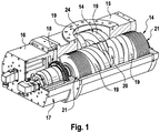
- a pump according to the invention in Fig. 1 includes two screws 14 received in a pump housing 15. One of the screws 14 is visible due to the pump housing 15 is not fully shown over the entire length, while the other screw 14 is substantially hidden by the pump housing 15. The two screws 14 are in engagement with each other, which means that the thread projections of a screw 14 in the recess between two threaded projections of the other screw 14 engage.
- the pump comprises a control and drive unit 16 in which an electronically controlled drive motor 17 is arranged for each of the screws 14.
- the electronic control of the drive motors 17 is set up so that the two screws 14 run completely synchronously with each other without the thread projections of the screws 14 touching each other.
- the two screws 14 are each equipped with a gear 18.
- the gears 18 are engaged with each other and cause a forced coupling of the two screws 14 in the event that the electronic synchronization of the screws 14 fails.
- Each screw 14 is provided with two threads 19 so that the pump has a total of four threads 19.
- the threads 19 each extend from a suction side 20 in the center of the screw 14 to a pressure side 21 at the outer ends of the screw 14.
- the two threads of a screw 14 are oriented in opposite directions, so that they work from the suction side 20 to the pressure side 21 out ,
- Each of the threads 19 comprises a first thread 22 and a second thread 23.
- the threads 19 are thus double-threaded in the sense that the threads 22, 23 are interlocked with each other so that together they form a double helical shape.
- the two threads 22, 23 are shaped so that the threads 19 are symmetrical in the radial direction. Looking at the screw 14 from the pressure side of the first thread 19 to the pressure side of second thread 19, so the screw 14 also has a longitudinal symmetry.
- the threads 19 are designed so that in the region of the suction side 20, a larger volume between two adjacent thread projections is included as in the region of the pressure side 21.
- the housing 15 of the pump is provided with an inlet opening 24 which is arranged to provide access to the suction sides 20 of all four threads 19.
- the inlet opening 24 has a large cross-section.
- the cross-sectional area of the inlet opening 24 is greater than the circular contour spanned by a screw 14.
- a suction gap 25 is formed on the housing 15 of the pump, which adjoins the inlet opening 24 and follows the contour of the screw 14 in the circumferential direction.
- the longitudinal direction of the suction gap 25 extends approximately over half the length of the thread 19 between the suction side 20 and the pressure side 21.
- the dimension of the suction gap 25 varies with the inlet opening, the farther the inlet opening 24 extends at the relevant site to the side , the shorter is the extent of the suction gap 25 in the circumferential direction at this point.
- the Suction gap 25 At the widest point of the inlet opening 24 extends the Suction gap 25 over a circumferential angle of about 45 °.
- the suction gap 24 extends over a circumferential angle of approximately 120 °.
- the dimension of the suction gap 25 in the radial direction corresponds to the distance between the pump housing 15 and the contour of the screw 14 in this area. This distance is on the order of about 10 mm.
- the gas is not limited to entering the working chambers in the radial direction, but the gas can also move through a thread projection into the working chamber through the suction gap. The volume flow into the working chamber is thereby further increased.
- Another contribution to increasing the volume flow into the working chamber is achieved in that there is a gap between the suction side 20 of the first thread 19 of a screw 14 and the suction side 20 of the second thread 19 of the screw 14. As a result, 14 space remains in the center of the screw, through which the gas can also enter in the radial direction in the working chamber.
- the distance between the housing and the contour of the screw 14 is as small as is technically possible (radial minimum distance).
- the compression takes place and leakage flow from one working chamber into the next working chamber is undesirable.
- a transition edge 28 is formed at the transition from the first housing section 26 to the second housing section 27, a transition edge 28 is formed.
- the transition edge 28 extends in the circumferential direction over the entire suction gap 25 and defines the transition from the suction gap 25 to the second housing portion 27, in which there is the minimum radial distance between the housing 15 and the screw 14.
- the compression begins as soon as the working chamber has merged into the second housing section, as soon as the thread projection which delimits the working chamber towards the suction side has concluded with the transition edge 28.
- the transition edge 28 is arranged so that the termination between the thread projection and the transition edge 28 takes place at a time when the working chamber still has its maximum volume.
- the transition edge 28 includes an angle with the transverse direction, which is smaller than the pitch of the thread projection, which terminates with the transition edge 28. This ensures that the conclusion between the thread projection and the transition edge 28 is not abrupt, but extends over a short period of time. This reduces the operating noise of the pump.
- the gas On the pressure side 21 of the thread 19, the gas is discharged from the working chamber. Through a bore 29 in the pump housing 15, the compressed gas is brought together from the outer pressure sides 21 to a central outlet opening.
- the outlet opening which is not visible in the figures, is disposed opposite the inlet opening 24.
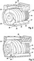
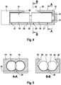
- the bore 29 is like the FIGS. 2, 3 and 5 show integrated into the pump housing 15 and extends between the two screws 14, wherein the line 29 is partially disposed within a resting on both screws 14 tangential surface 35.
- the pump according to the invention is constructed so that the control and drive unit 16 together with the screws 14 forms a structural unit, which can be pulled out of the housing 15 as such. If maintenance or repair is required, the assembly can be replaced without having to dislodge the pump housing 15 from the plant environment.
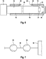
- a bearing 31 is arranged which sits firmly on the shaft and is slidably received in a bearing receptacle 34 of the pump housing 15.
- the bearing 31 is released from the bearing receptacle 34 and is also removed from the housing 15.
- FIG. 7 An application example of a screw pump according to the invention is in Fig. 7 shown where a pump assembly of a booster pump 30 and a backing pump 33 is connected to a space to be evacuated 32.
- the booster pump 30 is a screw pump according to the invention
- the fore pump 33 is a liquid ring vacuum pump.
- the pump arrangement is dimensioned so that from the space 32, a volume flow of 4000 m 3 / h can be sucked to keep the pressure in the space 32 at 0.5 mbar constant.
- the booster pump 30, whose screws 14 have a diameter of about 25 cm, operated at a speed of about 15,000 rpm.
- a pressure of about 50 mbar At the output of the booster pump 30 and thus at the input of the fore pump 33 is a pressure of about 50 mbar.
- this means for the backing pump 33 a volume flow of 400 m 3 / h.
- the backing pump 33 compresses this volume flow to atmospheric pressure and releases it to the environment.
Landscapes
- Engineering & Computer Science (AREA)
- Mechanical Engineering (AREA)
- General Engineering & Computer Science (AREA)
- Applications Or Details Of Rotary Compressors (AREA)
- Rotary Pumps (AREA)
- Details And Applications Of Rotary Liquid Pumps (AREA)
- Details Of Reciprocating Pumps (AREA)
- Structures Of Non-Positive Displacement Pumps (AREA)
Applications Claiming Priority (3)
| Application Number | Priority Date | Filing Date | Title |
|---|---|---|---|
| EP12174029 | 2012-06-28 | ||
| PCT/EP2013/062177 WO2014001089A1 (fr) | 2012-06-28 | 2013-06-12 | Pompe à vis |
| EP13729688.5A EP2867532B1 (fr) | 2012-06-28 | 2013-06-12 | Pompe à vis |
Related Parent Applications (2)
| Application Number | Title | Priority Date | Filing Date |
|---|---|---|---|
| EP13729688.5A Division EP2867532B1 (fr) | 2012-06-28 | 2013-06-12 | Pompe à vis |
| EP13729688.5A Division-Into EP2867532B1 (fr) | 2012-06-28 | 2013-06-12 | Pompe à vis |
Publications (3)
| Publication Number | Publication Date |
|---|---|
| EP3467314A2 true EP3467314A2 (fr) | 2019-04-10 |
| EP3467314A3 EP3467314A3 (fr) | 2019-04-17 |
| EP3467314B1 EP3467314B1 (fr) | 2021-08-04 |
Family
ID=48652047
Family Applications (2)
| Application Number | Title | Priority Date | Filing Date |
|---|---|---|---|
| EP18208219.8A Active EP3467314B1 (fr) | 2012-06-28 | 2013-06-12 | Pompe à vis |
| EP13729688.5A Active EP2867532B1 (fr) | 2012-06-28 | 2013-06-12 | Pompe à vis |
Family Applications After (1)
| Application Number | Title | Priority Date | Filing Date |
|---|---|---|---|
| EP13729688.5A Active EP2867532B1 (fr) | 2012-06-28 | 2013-06-12 | Pompe à vis |
Country Status (6)
| Country | Link |
|---|---|
| US (1) | US9845803B2 (fr) |
| EP (2) | EP3467314B1 (fr) |
| KR (1) | KR102024218B1 (fr) |
| CN (1) | CN104520587B (fr) |
| TW (1) | TWI589778B (fr) |
| WO (1) | WO2014001089A1 (fr) |
Families Citing this family (6)
| Publication number | Priority date | Publication date | Assignee | Title |
|---|---|---|---|---|
| CN105351750B (zh) * | 2015-11-10 | 2019-04-23 | 中国石油大学(华东) | 用于液环输送的液环维持装置 |
| CN106194727B (zh) * | 2016-08-15 | 2018-01-26 | 上海理工大学 | 环形单螺杆压缩机 |
| CN107044417B (zh) * | 2017-04-18 | 2019-08-02 | 王旭明 | 一种压缩空气循环动力装置 |
| CN110566456B (zh) * | 2019-09-12 | 2020-12-04 | 东莞市雅之雷德机电科技有限公司 | 一种无油螺杆风机 |
| CN111749884A (zh) * | 2020-06-12 | 2020-10-09 | 李奎 | 稳定性好的混输泵 |
| DE102020133760A1 (de) * | 2020-12-16 | 2022-06-23 | Leistritz Pumpen Gmbh | Verfahren zur Förderung eines Fluids durch eine Schraubenspindelpumpe und Schraubenspindelpumpe |
Family Cites Families (20)
| Publication number | Priority date | Publication date | Assignee | Title |
|---|---|---|---|---|
| US3057665A (en) * | 1960-06-24 | 1962-10-09 | Warren Pumps Inc | Pump |
| DE2117223A1 (de) | 1971-04-08 | 1972-10-12 | Maschinenfabrik Paul Leistritz, 8500 Nürnberg | Schraubenspindelpumpe |
| JP2619468B2 (ja) | 1988-04-06 | 1997-06-11 | 株式会社日立製作所 | 無給油式スクリュー流体機械 |
| JPH02305393A (ja) | 1989-05-19 | 1990-12-18 | Hitachi Ltd | スクリユーロータおよびスクリユー真空ポンプ |
| KR100190310B1 (ko) * | 1992-09-03 | 1999-06-01 | 모리시따 요오이찌 | 진공배기장치 |
| DE4426761C2 (de) * | 1994-07-22 | 2003-07-17 | Grasso Gmbh Refrigeration Tech | Schraubenverdichter |
| KR0133154B1 (ko) * | 1994-08-22 | 1998-04-20 | 이종대 | 무단 압축형 스크류식 진공펌프 |
| DE19522559A1 (de) | 1995-06-21 | 1997-01-02 | Sihi Ind Consult Gmbh | Verdichter mit axialer Förderrichtung, insbesondere in Schraubenspindel-Bauweise |
| FI104440B (fi) * | 1995-06-22 | 2000-01-31 | Kone Corp | Ruuvipumppu ja ruuvipumpun ruuvi |
| DE19748385A1 (de) * | 1997-11-03 | 1999-05-06 | Peter Frieden | Trockenlaufender Schraubenverdichter oder Vakuumpumpe |
| ES2219956T3 (es) | 1999-07-19 | 2004-12-01 | Sterling Fluid Systems (Germany) Gmbh | Maquina volumetrica para medios comprimibles. |
| JP2001207984A (ja) * | 1999-11-17 | 2001-08-03 | Teijin Seiki Co Ltd | 真空排気装置 |
| CN1330972A (zh) * | 2000-06-08 | 2002-01-16 | 乔丹技术公司 | 具有变速增压泵的蒸气回收系统 |
| CN100340769C (zh) * | 2005-12-22 | 2007-10-03 | 西安交通大学 | 一种用于高压系统的双螺杆压缩机 |
| CN1884834A (zh) * | 2006-07-10 | 2006-12-27 | 西安交通大学 | 一种双螺杆混输泵 |
| JP5353521B2 (ja) * | 2009-07-22 | 2013-11-27 | 株式会社豊田自動織機 | スクリューロータ |
| JP2011069309A (ja) * | 2009-09-28 | 2011-04-07 | Hitachi Industrial Equipment Systems Co Ltd | スクリュー圧縮機 |
| US20110158841A1 (en) * | 2009-12-28 | 2011-06-30 | Sunny King Machinery Co., Ltd. | Screw Pump with Anti-Turbulent Structure |
| CN201671811U (zh) * | 2010-05-27 | 2010-12-15 | 黄山工业泵制造有限公司 | 一种中低压双螺杆泵 |
| CN201836045U (zh) * | 2010-10-21 | 2011-05-18 | 中国石油化工股份有限公司 | 新型双螺杆胶液泵 |
-
2013
- 2013-06-12 EP EP18208219.8A patent/EP3467314B1/fr active Active
- 2013-06-12 US US14/409,002 patent/US9845803B2/en active Active
- 2013-06-12 WO PCT/EP2013/062177 patent/WO2014001089A1/fr not_active Ceased
- 2013-06-12 CN CN201380034163.5A patent/CN104520587B/zh active Active
- 2013-06-12 EP EP13729688.5A patent/EP2867532B1/fr active Active
- 2013-06-12 KR KR1020157002260A patent/KR102024218B1/ko active Active
- 2013-06-26 TW TW102122719A patent/TWI589778B/zh active
Non-Patent Citations (1)
| Title |
|---|
| None |
Also Published As
| Publication number | Publication date |
|---|---|
| US20160053761A1 (en) | 2016-02-25 |
| KR20150023901A (ko) | 2015-03-05 |
| EP3467314B1 (fr) | 2021-08-04 |
| EP2867532B1 (fr) | 2019-02-20 |
| US9845803B2 (en) | 2017-12-19 |
| CN104520587A (zh) | 2015-04-15 |
| KR102024218B1 (ko) | 2019-09-23 |
| WO2014001089A1 (fr) | 2014-01-03 |
| EP2867532A1 (fr) | 2015-05-06 |
| CN104520587B (zh) | 2016-12-07 |
| TW201405010A (zh) | 2014-02-01 |
| EP3467314A3 (fr) | 2019-04-17 |
| TWI589778B (zh) | 2017-07-01 |
Similar Documents
| Publication | Publication Date | Title |
|---|---|---|
| EP2867532B1 (fr) | Pompe à vis | |
| EP2867533B1 (fr) | Procédé et agencement de pompes pour l'évacuation d'une chambre | |
| EP3913187B1 (fr) | Pompe à vis | |
| EP0619430B1 (fr) | Pompe à engrenage internes pour gamme de vitesses rotatives élévées | |
| WO2009056200A1 (fr) | Pompe moineau | |
| DE2033201C3 (de) | Schraubenspindelmotor oder -pumpe | |
| EP3507496B1 (fr) | Pompe à vide à compression sèche | |
| DE1403541A1 (de) | Umlaufmaschine,insbesondere Schraubenverdichter fuer Gase | |
| EP3961035A1 (fr) | Procédé et pompe à broche hélicoïdale destinés au pompage d'un mélange gaz-liquide | |
| WO2000025004A1 (fr) | Rotors en forme de vis jumelee permettant le montage de machines de refoulement destinees a des agents compressibles | |
| EP3827170B1 (fr) | Dispositif de refoulement de fluide | |
| DE102014212920A1 (de) | Schaufelpumpe | |
| DE102007038966B4 (de) | Mehrstufige Drehkolbenvakuumpumpe bzw. - verdichter | |
| EP2745015A2 (fr) | Pompe roots | |
| DE102017201342A1 (de) | Wellenanordnung | |
| DE686298C (de) | Schraubenpumpen oder Schraubenmotoren mit zwei oder mehreren ineinandergreifenden Spindeln | |
| DE2134241C3 (de) | Zweistufige außenachsige Rotationskolbenmaschine | |
| WO2002103205A1 (fr) | Contour profile des rotors helicoidaux d'une pompe a vis | |
| WO2001079699A1 (fr) | Pompe a engrenages, en particulier pour pompe a carburant haute pression | |
| DE2411247A1 (de) | Hochvakuum-molekularpumpe mit zylindertrommel | |
| DE19614562A1 (de) | Schraubenpumpe | |
| WO2019076684A1 (fr) | Rotor à vis | |
| EP2581209A1 (fr) | Dispositif destiné au fonctionnement dýun piston plongeur | |
| WO2018019318A1 (fr) | Système rotor-stator comprenant une trémie d'entrée pour une pompe à vis excentrée | |
| WO2018189041A1 (fr) | Système de compresseur à vis, à engrenage de synchronisation et à engrenage de transmission |
Legal Events
| Date | Code | Title | Description |
|---|---|---|---|
| PUAI | Public reference made under article 153(3) epc to a published international application that has entered the european phase |
Free format text: ORIGINAL CODE: 0009012 |
|
| STAA | Information on the status of an ep patent application or granted ep patent |
Free format text: STATUS: THE APPLICATION HAS BEEN PUBLISHED |
|
| PUAL | Search report despatched |
Free format text: ORIGINAL CODE: 0009013 |
|
| AC | Divisional application: reference to earlier application |
Ref document number: 2867532 Country of ref document: EP Kind code of ref document: P |
|
| AK | Designated contracting states |
Kind code of ref document: A2 Designated state(s): AL AT BE BG CH CY CZ DE DK EE ES FI FR GB GR HR HU IE IS IT LI LT LU LV MC MK MT NL NO PL PT RO RS SE SI SK SM TR |
|
| AK | Designated contracting states |
Kind code of ref document: A3 Designated state(s): AL AT BE BG CH CY CZ DE DK EE ES FI FR GB GR HR HU IE IS IT LI LT LU LV MC MK MT NL NO PL PT RO RS SE SI SK SM TR |
|
| RIC1 | Information provided on ipc code assigned before grant |
Ipc: F04C 18/08 20060101AFI20190308BHEP Ipc: F04C 18/16 20060101ALI20190308BHEP |
|
| STAA | Information on the status of an ep patent application or granted ep patent |
Free format text: STATUS: REQUEST FOR EXAMINATION WAS MADE |
|
| 17P | Request for examination filed |
Effective date: 20190924 |
|
| RBV | Designated contracting states (corrected) |
Designated state(s): AL AT BE BG CH CY CZ DE DK EE ES FI FR GB GR HR HU IE IS IT LI LT LU LV MC MK MT NL NO PL PT RO RS SE SI SK SM TR |
|
| GRAP | Despatch of communication of intention to grant a patent |
Free format text: ORIGINAL CODE: EPIDOSNIGR1 |
|
| STAA | Information on the status of an ep patent application or granted ep patent |
Free format text: STATUS: GRANT OF PATENT IS INTENDED |
|
| RIC1 | Information provided on ipc code assigned before grant |
Ipc: F04C 18/08 20060101AFI20210121BHEP Ipc: F04C 18/16 20060101ALI20210121BHEP |
|
| INTG | Intention to grant announced |
Effective date: 20210219 |
|
| GRAS | Grant fee paid |
Free format text: ORIGINAL CODE: EPIDOSNIGR3 |
|
| GRAA | (expected) grant |
Free format text: ORIGINAL CODE: 0009210 |
|
| STAA | Information on the status of an ep patent application or granted ep patent |
Free format text: STATUS: THE PATENT HAS BEEN GRANTED |
|
| AC | Divisional application: reference to earlier application |
Ref document number: 2867532 Country of ref document: EP Kind code of ref document: P |
|
| AK | Designated contracting states |
Kind code of ref document: B1 Designated state(s): AL AT BE BG CH CY CZ DE DK EE ES FI FR GB GR HR HU IE IS IT LI LT LU LV MC MK MT NL NO PL PT RO RS SE SI SK SM TR |
|
| REG | Reference to a national code |
Ref country code: GB Ref legal event code: FG4D Free format text: NOT ENGLISH |
|
| REG | Reference to a national code |
Ref country code: AT Ref legal event code: REF Ref document number: 1417241 Country of ref document: AT Kind code of ref document: T Effective date: 20210815 |
|
| REG | Reference to a national code |
Ref country code: CH Ref legal event code: EP |
|
| REG | Reference to a national code |
Ref country code: DE Ref legal event code: R096 Ref document number: 502013015868 Country of ref document: DE |
|
| REG | Reference to a national code |
Ref country code: IE Ref legal event code: FG4D Free format text: LANGUAGE OF EP DOCUMENT: GERMAN |
|
| REG | Reference to a national code |
Ref country code: LT Ref legal event code: MG9D |
|
| REG | Reference to a national code |
Ref country code: NL Ref legal event code: MP Effective date: 20210804 |
|
| PG25 | Lapsed in a contracting state [announced via postgrant information from national office to epo] |
Ref country code: RS Free format text: LAPSE BECAUSE OF FAILURE TO SUBMIT A TRANSLATION OF THE DESCRIPTION OR TO PAY THE FEE WITHIN THE PRESCRIBED TIME-LIMIT Effective date: 20210804 Ref country code: SE Free format text: LAPSE BECAUSE OF FAILURE TO SUBMIT A TRANSLATION OF THE DESCRIPTION OR TO PAY THE FEE WITHIN THE PRESCRIBED TIME-LIMIT Effective date: 20210804 Ref country code: HR Free format text: LAPSE BECAUSE OF FAILURE TO SUBMIT A TRANSLATION OF THE DESCRIPTION OR TO PAY THE FEE WITHIN THE PRESCRIBED TIME-LIMIT Effective date: 20210804 Ref country code: FI Free format text: LAPSE BECAUSE OF FAILURE TO SUBMIT A TRANSLATION OF THE DESCRIPTION OR TO PAY THE FEE WITHIN THE PRESCRIBED TIME-LIMIT Effective date: 20210804 Ref country code: ES Free format text: LAPSE BECAUSE OF FAILURE TO SUBMIT A TRANSLATION OF THE DESCRIPTION OR TO PAY THE FEE WITHIN THE PRESCRIBED TIME-LIMIT Effective date: 20210804 Ref country code: PT Free format text: LAPSE BECAUSE OF FAILURE TO SUBMIT A TRANSLATION OF THE DESCRIPTION OR TO PAY THE FEE WITHIN THE PRESCRIBED TIME-LIMIT Effective date: 20211206 Ref country code: NO Free format text: LAPSE BECAUSE OF FAILURE TO SUBMIT A TRANSLATION OF THE DESCRIPTION OR TO PAY THE FEE WITHIN THE PRESCRIBED TIME-LIMIT Effective date: 20211104 Ref country code: BG Free format text: LAPSE BECAUSE OF FAILURE TO SUBMIT A TRANSLATION OF THE DESCRIPTION OR TO PAY THE FEE WITHIN THE PRESCRIBED TIME-LIMIT Effective date: 20211104 Ref country code: LT Free format text: LAPSE BECAUSE OF FAILURE TO SUBMIT A TRANSLATION OF THE DESCRIPTION OR TO PAY THE FEE WITHIN THE PRESCRIBED TIME-LIMIT Effective date: 20210804 |
|
| PG25 | Lapsed in a contracting state [announced via postgrant information from national office to epo] |
Ref country code: PL Free format text: LAPSE BECAUSE OF FAILURE TO SUBMIT A TRANSLATION OF THE DESCRIPTION OR TO PAY THE FEE WITHIN THE PRESCRIBED TIME-LIMIT Effective date: 20210804 Ref country code: LV Free format text: LAPSE BECAUSE OF FAILURE TO SUBMIT A TRANSLATION OF THE DESCRIPTION OR TO PAY THE FEE WITHIN THE PRESCRIBED TIME-LIMIT Effective date: 20210804 Ref country code: GR Free format text: LAPSE BECAUSE OF FAILURE TO SUBMIT A TRANSLATION OF THE DESCRIPTION OR TO PAY THE FEE WITHIN THE PRESCRIBED TIME-LIMIT Effective date: 20211105 |
|
| PG25 | Lapsed in a contracting state [announced via postgrant information from national office to epo] |
Ref country code: NL Free format text: LAPSE BECAUSE OF FAILURE TO SUBMIT A TRANSLATION OF THE DESCRIPTION OR TO PAY THE FEE WITHIN THE PRESCRIBED TIME-LIMIT Effective date: 20210804 |
|
| PG25 | Lapsed in a contracting state [announced via postgrant information from national office to epo] |
Ref country code: DK Free format text: LAPSE BECAUSE OF FAILURE TO SUBMIT A TRANSLATION OF THE DESCRIPTION OR TO PAY THE FEE WITHIN THE PRESCRIBED TIME-LIMIT Effective date: 20210804 |
|
| REG | Reference to a national code |
Ref country code: DE Ref legal event code: R097 Ref document number: 502013015868 Country of ref document: DE |
|
| PG25 | Lapsed in a contracting state [announced via postgrant information from national office to epo] |
Ref country code: SM Free format text: LAPSE BECAUSE OF FAILURE TO SUBMIT A TRANSLATION OF THE DESCRIPTION OR TO PAY THE FEE WITHIN THE PRESCRIBED TIME-LIMIT Effective date: 20210804 Ref country code: SK Free format text: LAPSE BECAUSE OF FAILURE TO SUBMIT A TRANSLATION OF THE DESCRIPTION OR TO PAY THE FEE WITHIN THE PRESCRIBED TIME-LIMIT Effective date: 20210804 Ref country code: RO Free format text: LAPSE BECAUSE OF FAILURE TO SUBMIT A TRANSLATION OF THE DESCRIPTION OR TO PAY THE FEE WITHIN THE PRESCRIBED TIME-LIMIT Effective date: 20210804 Ref country code: EE Free format text: LAPSE BECAUSE OF FAILURE TO SUBMIT A TRANSLATION OF THE DESCRIPTION OR TO PAY THE FEE WITHIN THE PRESCRIBED TIME-LIMIT Effective date: 20210804 Ref country code: CZ Free format text: LAPSE BECAUSE OF FAILURE TO SUBMIT A TRANSLATION OF THE DESCRIPTION OR TO PAY THE FEE WITHIN THE PRESCRIBED TIME-LIMIT Effective date: 20210804 Ref country code: AL Free format text: LAPSE BECAUSE OF FAILURE TO SUBMIT A TRANSLATION OF THE DESCRIPTION OR TO PAY THE FEE WITHIN THE PRESCRIBED TIME-LIMIT Effective date: 20210804 |
|
| PLBE | No opposition filed within time limit |
Free format text: ORIGINAL CODE: 0009261 |
|
| STAA | Information on the status of an ep patent application or granted ep patent |
Free format text: STATUS: NO OPPOSITION FILED WITHIN TIME LIMIT |
|
| 26N | No opposition filed |
Effective date: 20220506 |
|
| PG25 | Lapsed in a contracting state [announced via postgrant information from national office to epo] |
Ref country code: IT Free format text: LAPSE BECAUSE OF FAILURE TO SUBMIT A TRANSLATION OF THE DESCRIPTION OR TO PAY THE FEE WITHIN THE PRESCRIBED TIME-LIMIT Effective date: 20210804 |
|
| PG25 | Lapsed in a contracting state [announced via postgrant information from national office to epo] |
Ref country code: SI Free format text: LAPSE BECAUSE OF FAILURE TO SUBMIT A TRANSLATION OF THE DESCRIPTION OR TO PAY THE FEE WITHIN THE PRESCRIBED TIME-LIMIT Effective date: 20210804 |
|
| PG25 | Lapsed in a contracting state [announced via postgrant information from national office to epo] |
Ref country code: MC Free format text: LAPSE BECAUSE OF FAILURE TO SUBMIT A TRANSLATION OF THE DESCRIPTION OR TO PAY THE FEE WITHIN THE PRESCRIBED TIME-LIMIT Effective date: 20210804 |
|
| REG | Reference to a national code |
Ref country code: CH Ref legal event code: PL |
|
| REG | Reference to a national code |
Ref country code: BE Ref legal event code: MM Effective date: 20220630 |
|
| PG25 | Lapsed in a contracting state [announced via postgrant information from national office to epo] |
Ref country code: LU Free format text: LAPSE BECAUSE OF NON-PAYMENT OF DUE FEES Effective date: 20220612 Ref country code: LI Free format text: LAPSE BECAUSE OF NON-PAYMENT OF DUE FEES Effective date: 20220630 Ref country code: IE Free format text: LAPSE BECAUSE OF NON-PAYMENT OF DUE FEES Effective date: 20220612 Ref country code: CH Free format text: LAPSE BECAUSE OF NON-PAYMENT OF DUE FEES Effective date: 20220630 |
|
| PG25 | Lapsed in a contracting state [announced via postgrant information from national office to epo] |
Ref country code: BE Free format text: LAPSE BECAUSE OF NON-PAYMENT OF DUE FEES Effective date: 20220630 |
|
| REG | Reference to a national code |
Ref country code: AT Ref legal event code: MM01 Ref document number: 1417241 Country of ref document: AT Kind code of ref document: T Effective date: 20220612 |
|
| PG25 | Lapsed in a contracting state [announced via postgrant information from national office to epo] |
Ref country code: AT Free format text: LAPSE BECAUSE OF NON-PAYMENT OF DUE FEES Effective date: 20220612 |
|
| PG25 | Lapsed in a contracting state [announced via postgrant information from national office to epo] |
Ref country code: HU Free format text: LAPSE BECAUSE OF FAILURE TO SUBMIT A TRANSLATION OF THE DESCRIPTION OR TO PAY THE FEE WITHIN THE PRESCRIBED TIME-LIMIT; INVALID AB INITIO Effective date: 20130612 |
|
| PG25 | Lapsed in a contracting state [announced via postgrant information from national office to epo] |
Ref country code: MK Free format text: LAPSE BECAUSE OF FAILURE TO SUBMIT A TRANSLATION OF THE DESCRIPTION OR TO PAY THE FEE WITHIN THE PRESCRIBED TIME-LIMIT Effective date: 20210804 Ref country code: CY Free format text: LAPSE BECAUSE OF FAILURE TO SUBMIT A TRANSLATION OF THE DESCRIPTION OR TO PAY THE FEE WITHIN THE PRESCRIBED TIME-LIMIT Effective date: 20210804 |
|
| PG25 | Lapsed in a contracting state [announced via postgrant information from national office to epo] |
Ref country code: MT Free format text: LAPSE BECAUSE OF FAILURE TO SUBMIT A TRANSLATION OF THE DESCRIPTION OR TO PAY THE FEE WITHIN THE PRESCRIBED TIME-LIMIT Effective date: 20210804 |
|
| PGFP | Annual fee paid to national office [announced via postgrant information from national office to epo] |
Ref country code: DE Payment date: 20250627 Year of fee payment: 13 |
|
| PGFP | Annual fee paid to national office [announced via postgrant information from national office to epo] |
Ref country code: GB Payment date: 20250627 Year of fee payment: 13 |
|
| PGFP | Annual fee paid to national office [announced via postgrant information from national office to epo] |
Ref country code: FR Payment date: 20250625 Year of fee payment: 13 |
|
| PG25 | Lapsed in a contracting state [announced via postgrant information from national office to epo] |
Ref country code: TR Free format text: LAPSE BECAUSE OF FAILURE TO SUBMIT A TRANSLATION OF THE DESCRIPTION OR TO PAY THE FEE WITHIN THE PRESCRIBED TIME-LIMIT Effective date: 20210804 |