EP2867533B1 - Procédé et agencement de pompes pour l'évacuation d'une chambre - Google Patents
Procédé et agencement de pompes pour l'évacuation d'une chambre Download PDFInfo
- Publication number
- EP2867533B1 EP2867533B1 EP13727952.7A EP13727952A EP2867533B1 EP 2867533 B1 EP2867533 B1 EP 2867533B1 EP 13727952 A EP13727952 A EP 13727952A EP 2867533 B1 EP2867533 B1 EP 2867533B1
- Authority
- EP
- European Patent Office
- Prior art keywords
- booster pump
- pump
- chamber
- gas
- housing
- Prior art date
- Legal status (The legal status is an assumption and is not a legal conclusion. Google has not performed a legal analysis and makes no representation as to the accuracy of the status listed.)
- Active
Links
Images


Classifications
-
- F—MECHANICAL ENGINEERING; LIGHTING; HEATING; WEAPONS; BLASTING
- F04—POSITIVE - DISPLACEMENT MACHINES FOR LIQUIDS; PUMPS FOR LIQUIDS OR ELASTIC FLUIDS
- F04C—ROTARY-PISTON, OR OSCILLATING-PISTON, POSITIVE-DISPLACEMENT MACHINES FOR LIQUIDS; ROTARY-PISTON, OR OSCILLATING-PISTON, POSITIVE-DISPLACEMENT PUMPS
- F04C28/00—Control of, monitoring of, or safety arrangements for, pumps or pumping installations specially adapted for elastic fluids
- F04C28/02—Control of, monitoring of, or safety arrangements for, pumps or pumping installations specially adapted for elastic fluids specially adapted for several pumps connected in series or in parallel
-
- F—MECHANICAL ENGINEERING; LIGHTING; HEATING; WEAPONS; BLASTING
- F04—POSITIVE - DISPLACEMENT MACHINES FOR LIQUIDS; PUMPS FOR LIQUIDS OR ELASTIC FLUIDS
- F04C—ROTARY-PISTON, OR OSCILLATING-PISTON, POSITIVE-DISPLACEMENT MACHINES FOR LIQUIDS; ROTARY-PISTON, OR OSCILLATING-PISTON, POSITIVE-DISPLACEMENT PUMPS
- F04C14/00—Control of, monitoring of, or safety arrangements for, machines, pumps or pumping installations
- F04C14/08—Control of, monitoring of, or safety arrangements for, machines, pumps or pumping installations characterised by varying the rotational speed
-
- F—MECHANICAL ENGINEERING; LIGHTING; HEATING; WEAPONS; BLASTING
- F04—POSITIVE - DISPLACEMENT MACHINES FOR LIQUIDS; PUMPS FOR LIQUIDS OR ELASTIC FLUIDS
- F04C—ROTARY-PISTON, OR OSCILLATING-PISTON, POSITIVE-DISPLACEMENT MACHINES FOR LIQUIDS; ROTARY-PISTON, OR OSCILLATING-PISTON, POSITIVE-DISPLACEMENT PUMPS
- F04C18/00—Rotary-piston pumps specially adapted for elastic fluids
- F04C18/08—Rotary-piston pumps specially adapted for elastic fluids of intermeshing-engagement type, i.e. with engagement of co-operating members similar to that of toothed gearing
- F04C18/12—Rotary-piston pumps specially adapted for elastic fluids of intermeshing-engagement type, i.e. with engagement of co-operating members similar to that of toothed gearing of other than internal-axis type
- F04C18/14—Rotary-piston pumps specially adapted for elastic fluids of intermeshing-engagement type, i.e. with engagement of co-operating members similar to that of toothed gearing of other than internal-axis type with toothed rotary pistons
- F04C18/16—Rotary-piston pumps specially adapted for elastic fluids of intermeshing-engagement type, i.e. with engagement of co-operating members similar to that of toothed gearing of other than internal-axis type with toothed rotary pistons with helical teeth, e.g. chevron-shaped, screw type
-
- F—MECHANICAL ENGINEERING; LIGHTING; HEATING; WEAPONS; BLASTING
- F04—POSITIVE - DISPLACEMENT MACHINES FOR LIQUIDS; PUMPS FOR LIQUIDS OR ELASTIC FLUIDS
- F04C—ROTARY-PISTON, OR OSCILLATING-PISTON, POSITIVE-DISPLACEMENT MACHINES FOR LIQUIDS; ROTARY-PISTON, OR OSCILLATING-PISTON, POSITIVE-DISPLACEMENT PUMPS
- F04C2/00—Rotary-piston machines or pumps
- F04C2/08—Rotary-piston machines or pumps of intermeshing-engagement type, i.e. with engagement of co-operating members similar to that of toothed gearing
- F04C2/10—Rotary-piston machines or pumps of intermeshing-engagement type, i.e. with engagement of co-operating members similar to that of toothed gearing of internal-axis type with the outer member having more teeth or tooth-equivalents, e.g. rollers, than the inner member
-
- F—MECHANICAL ENGINEERING; LIGHTING; HEATING; WEAPONS; BLASTING
- F04—POSITIVE - DISPLACEMENT MACHINES FOR LIQUIDS; PUMPS FOR LIQUIDS OR ELASTIC FLUIDS
- F04C—ROTARY-PISTON, OR OSCILLATING-PISTON, POSITIVE-DISPLACEMENT MACHINES FOR LIQUIDS; ROTARY-PISTON, OR OSCILLATING-PISTON, POSITIVE-DISPLACEMENT PUMPS
- F04C23/00—Combinations of two or more pumps, each being of rotary-piston or oscillating-piston type, specially adapted for elastic fluids; Pumping installations specially adapted for elastic fluids; Multi-stage pumps specially adapted for elastic fluids
- F04C23/005—Combinations of two or more pumps, each being of rotary-piston or oscillating-piston type, specially adapted for elastic fluids; Pumping installations specially adapted for elastic fluids; Multi-stage pumps specially adapted for elastic fluids of dissimilar working principle
-
- F—MECHANICAL ENGINEERING; LIGHTING; HEATING; WEAPONS; BLASTING
- F04—POSITIVE - DISPLACEMENT MACHINES FOR LIQUIDS; PUMPS FOR LIQUIDS OR ELASTIC FLUIDS
- F04C—ROTARY-PISTON, OR OSCILLATING-PISTON, POSITIVE-DISPLACEMENT MACHINES FOR LIQUIDS; ROTARY-PISTON, OR OSCILLATING-PISTON, POSITIVE-DISPLACEMENT PUMPS
- F04C25/00—Adaptations of pumps for special use of pumps for elastic fluids
- F04C25/02—Adaptations of pumps for special use of pumps for elastic fluids for producing high vacuum
-
- F—MECHANICAL ENGINEERING; LIGHTING; HEATING; WEAPONS; BLASTING
- F04—POSITIVE - DISPLACEMENT MACHINES FOR LIQUIDS; PUMPS FOR LIQUIDS OR ELASTIC FLUIDS
- F04C—ROTARY-PISTON, OR OSCILLATING-PISTON, POSITIVE-DISPLACEMENT MACHINES FOR LIQUIDS; ROTARY-PISTON, OR OSCILLATING-PISTON, POSITIVE-DISPLACEMENT PUMPS
- F04C28/00—Control of, monitoring of, or safety arrangements for, pumps or pumping installations specially adapted for elastic fluids
- F04C28/06—Control of, monitoring of, or safety arrangements for, pumps or pumping installations specially adapted for elastic fluids specially adapted for stopping, starting, idling or no-load operation
-
- F—MECHANICAL ENGINEERING; LIGHTING; HEATING; WEAPONS; BLASTING
- F04—POSITIVE - DISPLACEMENT MACHINES FOR LIQUIDS; PUMPS FOR LIQUIDS OR ELASTIC FLUIDS
- F04C—ROTARY-PISTON, OR OSCILLATING-PISTON, POSITIVE-DISPLACEMENT MACHINES FOR LIQUIDS; ROTARY-PISTON, OR OSCILLATING-PISTON, POSITIVE-DISPLACEMENT PUMPS
- F04C18/00—Rotary-piston pumps specially adapted for elastic fluids
- F04C18/08—Rotary-piston pumps specially adapted for elastic fluids of intermeshing-engagement type, i.e. with engagement of co-operating members similar to that of toothed gearing
- F04C18/082—Details specially related to intermeshing engagement type pumps
- F04C18/084—Toothed wheels
-
- F—MECHANICAL ENGINEERING; LIGHTING; HEATING; WEAPONS; BLASTING
- F04—POSITIVE - DISPLACEMENT MACHINES FOR LIQUIDS; PUMPS FOR LIQUIDS OR ELASTIC FLUIDS
- F04C—ROTARY-PISTON, OR OSCILLATING-PISTON, POSITIVE-DISPLACEMENT MACHINES FOR LIQUIDS; ROTARY-PISTON, OR OSCILLATING-PISTON, POSITIVE-DISPLACEMENT PUMPS
- F04C18/00—Rotary-piston pumps specially adapted for elastic fluids
- F04C18/08—Rotary-piston pumps specially adapted for elastic fluids of intermeshing-engagement type, i.e. with engagement of co-operating members similar to that of toothed gearing
- F04C18/082—Details specially related to intermeshing engagement type pumps
- F04C18/086—Carter
-
- F—MECHANICAL ENGINEERING; LIGHTING; HEATING; WEAPONS; BLASTING
- F04—POSITIVE - DISPLACEMENT MACHINES FOR LIQUIDS; PUMPS FOR LIQUIDS OR ELASTIC FLUIDS
- F04C—ROTARY-PISTON, OR OSCILLATING-PISTON, POSITIVE-DISPLACEMENT MACHINES FOR LIQUIDS; ROTARY-PISTON, OR OSCILLATING-PISTON, POSITIVE-DISPLACEMENT PUMPS
- F04C2220/00—Application
- F04C2220/30—Use in a chemical vapor deposition [CVD] process or in a similar process
Definitions
- the invention relates to a method and a pump assembly for evacuating a chamber.
- the pump assembly which is connected to the chamber, includes a booster pump and a subsequent backing pump.
- Such a pump arrangement is known from WO 2006/082366 known.
- a chamber is evacuated within a short time to a predetermined vacuum.
- An example are lock chambers, through which products are introduced into a vacuum space.
- the products may be, for example, bulk goods such as solar cells, displays, etc., in which individual manufacturing steps are carried out in the vacuum space.
- Such products are to be introduced with ever shorter cycle times in the vacuum space.
- lock chambers with a volume of a few 100 l to be evacuated in significantly less than 10 s to a pressure of less than 10 -2 mbar.
- Pump assemblies of two pumps connected in series are usually used to evacuate such lock chambers, the first pump usually being referred to as a booster pump and the subsequent pump as a fore pump.
- the invention is based on the object to present a method and a pump assembly that allow the rapid evacuation of a chamber with reduced equipment expense. Based on the above-mentioned prior art, the object is achieved with the features of the independent claims. Advantageous embodiments can be found in the subclaims.
- the booster pump is first accelerated when the input is closed. Gas from the chamber to be evacuated is then admitted into the booster pump, so that the booster pump is temporarily removed an excess power that goes beyond the power provided by the drive of the booster pump.
- the gas delivered to the booster pump outlet is delivered through a bypass valve as long as the output pressure of the booster pump is above a predetermined threshold.
- the gas is sent to the fore pump when the output pressure of the booster pump has dropped below the threshold.
- the gas supplied by the booster pump is compressed by the forepump.
- booster pump and fore pump clarify the order of the pump in the pump arrangement.
- a limitation with regard to the design of the pump is not associated with these terms.
- the invention has recognized that it is possible by accelerating the booster pump and the subsequent removal of the excess power to promote the gas from the chamber under such high pressure to the output of the booster pump that the gas can be discharged directly bypassing the fore pump. Only when the evacuation process has progressed so far that the booster pump is no longer able to compress the gas to the appropriate pressure, the fore pump is added for further compression.
- the invention makes it possible to design the backing pump not only for a smaller volume flow, but also for a smaller mass flow than the booster pump.
- the outlet of the bypass valve is at atmospheric pressure.
- the threshold value corresponds in this case to the atmospheric pressure. So the gas exits through the bypass valve, as long as the output pressure of the booster pump is above the atmospheric pressure.
- the outlet pressure of the booster pump can be at least 1 bar, preferably at least 2 bar, more preferably at least 3 bar above atmospheric pressure.
- the compressed with the forepumping gas can also be discharged at atmospheric pressure to the environment.
- the evacuation process is in the chamber regularly at atmospheric pressure, so that the evacuation process starts at atmospheric pressure.
- the input of the booster pump is closed, so that no gas from the chamber can enter the booster pump.
- the evacuation process then begins at the time gas is introduced into the booster pump.
- the booster pump In order to be able to deliver a large volume flow at high pressure (e.g., atmospheric pressure) at the beginning of the evacuation process, the booster pump must provide a high compression capacity.
- the high compression capacity is provided by temporarily removing more compression power from the booster pump during the evacuation process than the booster pump drive provides. The excess power beyond the drive power is taken from the kinetic energy of the booster pump. The booster pump is thus braked and the speed of the pump is reduced.
- the power taken in the booster pump can be very clearly above the drive power. It is possible, for example, that the excess power in the tip is more than 50%, preferably more than 100%, more preferably more than 200% of the drive power. With an oversize performance of 100%, the compression capacity is twice as high as the drive power.
- the excess power is not only taken momentarily, but over a certain period of time.
- the period during which excess pressure is taken for example, over 10%, preferably more than 20%, more preferably extend over 50% of the evacuation process.
- the speed of the booster pump can be reduced by removing the excess power by at least 5%, preferably at least 10%, more preferably at least 25% percent.
- the pump In order for it to be possible to remove excess power from the pump to such an extent, the pump must be set to a state in which sufficient kinetic energy is available before the evacuation process begins. The pump is therefore accelerated before the start of the evacuation process.
- the speed of the booster pump at the beginning of the evacuation process is preferably higher than 8000 rpm, more preferably higher than 10,000 rpm, more preferably higher than 12000 rpm.
- the diameter of the parts in rotation is preferably greater than 5 cm, more preferably greater than 10 cm, more preferably greater than 20 cm.
- booster pump If the gas is admitted from the chamber at substantially atmospheric pressure in the booster pump, the booster pump is exposed to a sudden load.
- a screw pump is used as a booster pump, whose preferred design is explained in more detail below.
- the forepump can for example, be a conventional liquid ring vacuum pump.
- the period in which the booster pump is taken excess power for example, 1 s
- the period of removal of excess power is preferably at least 5%, more preferably at least 10% of the cycle time.
- the power taken from the booster pump is less than the drive power, so that the booster pump is accelerated.
- the invention also relates to a pump arrangement.
- the pump arrangement comprises a booster pump and a fore pump, wherein the output of the booster pump is connected to the input of the fore pump. Between the booster pump and the fore pump, a bypass valve is arranged, through which the pumped with the booster pump gas can be delivered bypassing the backing pump.
- the pump assembly further includes a controller configured to provide a control signal when the speed of the booster pump is above a predetermined speed threshold. The speed threshold value is set so that the booster pump is ready for the removal of an excess power after exceeding the relevant speed.
- Such a pump arrangement is suitable for evacuating a chamber according to the method according to the invention in a short time.
- the control signal may be communicated to a controller of the chamber to be evacuated to notify that the booster pump is ready for the next evacuation process.
- the control of the chamber can then open the input of the booster pump via which the booster pump is connected to the chamber.
- the gas from the chamber then enters the booster pump and the chamber is evacuated quickly. With the entry of the gas into the booster pump, the load increases abruptly, so that the speed of the booster pump is reduced.
- the control unit of the booster pump can also be designed to accelerate the booster pump before the start of the evacuation process so that the speed threshold is exceeded.
- the speed threshold is preferably above the delivery speed of the booster pump. Delivery speed refers to the speed, which is set as a stationary state when the intake pressure is 100 mbar.
- the drive power at pump speed corresponds to the pump power, which means that the speed of the booster pump remains constant.
- the speed threshold may be 10%, preferably 30%, more preferably 50% higher than the delivery speed. In absolute terms, the speed threshold value may be, for example, at least 8,000 rpm, preferably at least 10,000 rpm, more preferably at least 12,000 rpm.
- booster pumps which are considered for an application within the scope of the invention, operated at much lower speeds. A speed of 6,000 rpm is not regularly exceeded during the operation of such booster pumps. Also in the method according to the invention, the booster pump can be accelerated beyond the delivery speed.
- the arrangement according to the invention can also comprise the chamber to be evacuated.
- the controller of the assembly may then be configured to open the input of the pump via which the booster pump is connected to the chamber after the speed threshold has been exceeded. Further, the controller may be configured to keep the input closed while the booster pump is accelerating.
- a screw pump is used as booster pump, in which the screws of two threads are engaged with each other so that the gas is conveyed between the threads from a suction side to a pressure side.
- the screws preferably have two threads, so that the forces occurring in the longitudinal direction of the screws cancel each other out.
- the threads of the screw are preferably formed slaughter marc.
- a point symmetry of the screws can be such that the screws are imaged by themselves by a rotation about the longitudinal axis by 180 °.
- the diameter of the screws is preferably greater than 10 cm, more preferably greater than 15 cm, more preferably greater than 20 cm, so that the screws in sum have about the above mass.
- the inlet opening is preferably greater than 60%, more preferably greater than 80%, more preferably greater than 100% of the cross-sectional area of a screw.
- minimum radial distance for example, less than 0.2 mm, preferably less than 0.1 mm.
- the inlet region there may be a suction gap between the thread of the screw and the housing in order to allow a high volume flow into the working chambers of the pumps.
- the radial diameter of the suction gap is preferably greater than the radial minimum distance by a factor of 50, more preferably by a factor of 100, more preferably by a factor of 200.
- the suction gap may, for example, extend over a circumferential angle of at least 15 °, preferably at least 30 °, of the housing. In the longitudinal direction of the suction gap can be over at least 20%, preferably at least 30%, on preferably at least 40% of the length of a thread of the screw extend.
- the length of the suction gap preferably corresponds to the length of a 360 ° turn of the thread in this area.
- the thread has a very large slope in the inlet area.
- the first 360 ° winding may, for example, extend over at least 20%, preferably at least 30%, more preferably at least 40% of the length of the thread.
- each thread of the double-threaded thread preferably comprises at least three, more preferably at least four full 360 ° windings.
- the simplified block product 41 may be For example, be a variety of semiconductor devices, such as solar cells or displays.
- the process step may be a coating process.
- Adjoining the vacuum space 40 is a lock with a lock chamber 42, through which the product 41 is introduced into the vacuum chamber.
- the lock chamber 42 has an entrance opening and an exit opening provided with sliding doors 43, 44.
- the sliding doors 43, 44 are controlled by a controller 50 so that at no time are both opened at the same time. When the sliding door 43 is opened, there is atmospheric pressure in the lock chamber 42.
- the lock has a volume of, for example, 200 l.
- the product 41 can be moved into the lock chamber 42 by means of treadmills 45.
- the lock chamber 42 is evacuated by a pump arrangement connected to the lock chamber 42, so that the pressure in the lock chamber 42 corresponds to the pressure in the vacuum space 40 of less than 0.5 mbar.
- the sliding door 44 is opened and the product 41 is retracted with the treadmills 45 in the vacuum space 40.
- the sliding door 44 is closed again, brought the lock chamber 42 to atmospheric pressure and the sliding door 43 is opened. This is a cycle in the lock completed.
- the cycle time of the cycle is about 10 s.
- the evacuation process by which the pressure in the lock chamber is reduced from atmospheric pressure to a final pressure of less than 0.5 mbar, there is a period of time that is significantly below the cycle time.
- the evacuation process may extend over a period of 5 seconds.
- a powerful pump assembly is required, which has a high pumping speed, in particular in the entire pressure range between atmospheric pressure and final pressure.
- a screw pump as a booster pump 46 and a liquid ring vacuum pump as a fore pump 47 are connected in series.
- the liquid ring vacuum pump is conventionally designed so that a detailed description is not required.
- the booster pump 46 is first accelerated to a speed that is significantly above the delivery speed.
- a valve 48 arranged between the booster pump 46 and the lock chamber 42 is closed, so that no gas from the lock chamber 42 can enter the inlet of the booster pump 46.
- the booster pump 46 is thus not under load, so that a comparatively low drive power is sufficient to accelerate the booster pump 46.
- the booster pump 46 If the booster pump 46 is accelerated so far that a predetermined speed threshold is exceeded, sends a control unit 16 of the booster pump 46, a control signal to the controller 50 of the lock chamber.
- the controller 50 thus receives the information that the booster pump 46 is ready for the next evacuation process.
- the controller 50 may open the valve 48 so that the booster pump 46 may draw air from the lock chamber 42.
- the air is conveyed by the booster pump 46 and thereby compressed, so that at the output of the booster pump 46, a pressure is applied, which is well above the atmospheric pressure. In the top, for example, a pressure of 3 bar above the atmospheric pressure abut the output of the booster pump 46.
- a bypass valve 49 is arranged, at the output of which atmospheric pressure is applied.
- the bypass valve 49 is designed as a pressure relief valve, so that the compressed gas from the outlet of the booster pump 46 automatically exits via the bypass valve 49, as long as the pressure at the outlet of the booster pump 46 is above atmospheric pressure. If the pressure at the outlet of the booster pump 46 drops below atmospheric pressure, the bypass valve 49 closes. The gas is then taken over by the forepump 47 and further compressed in such a way that it can be released to the environment at atmospheric pressure.
- the forepump 47 is designed so that it can compress the gas to atmospheric pressure from this pressure.
- the booster pump 46 is accelerated to a high speed of more than 10,000 rpm before the start of the evacuation process. By removing the excess power, the speed decreases within 1 s to 9000 U / min. The remaining cycle time is used to accelerate the booster pump 46 back to its original speed. The drive power is therefore higher in this phase than the booster pump 46 taken compression power.
- a booster pump 46 which on the one hand withstands the loads at the beginning of the evacuation process and on the other hand has the required pumping speed over the entire pressure range is described below.
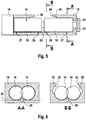
- the suitable as a booster pump screw pump comprises according to Fig. 2 two screws 14 which are accommodated in a pump housing 15.
- One of the screws 14 is due to the not fully illustrated pump housing 15 visible over the entire length, while the other screw 14 is covered to a considerable extent by the pump housing 15.
- the two screws 14 are engaged with each other, which means that the thread projections of a screw 14 engage in the recess between two thread projections of the other screw 14.
- the pump comprises a control and drive unit 16 in which an electronically controlled drive motor 17 is arranged for each of the screws 14.
- the electronic control of the drive motors 17 is set up so that the two screws 14 run completely synchronously with each other without the thread projections of the screws 14 touching each other.
- the two screws 14 are each equipped with a gear 18.
- the gears 18 are engaged with each other and cause a forced coupling of the two screws 14 in the event that the electronic synchronization of the screws 14 fails.
- Each screw 14 is provided with two threads 19 so that the pump has a total of four threads 19.
- the threads 19 each extend from a suction side 20 in the center of the screw 14 to a pressure side 21 at the outer ends of the screw 14.
- the two threads of a screw 14 are oriented in opposite directions, so that they work from the suction side 20 to the pressure side 21 out ,
- Each of the threads 19 comprises a first thread 22 and a second thread 23.
- the threads 19 are thus double-threaded in the sense that the threads 22, 23 are interlocked with each other, so that they together form a double helical Form form.
- the two threads 22, 23 are shaped so that the threads 19 are symmetrical in the radial direction. Considering the screw 14 from the pressure side of the first thread 19 to the pressure side of the second thread 19, the screw 14 also has a longitudinal symmetry.
- the threads 19 are designed so that in the region of the suction side 20, a larger volume between two adjacent thread projections is included as in the region of the pressure side 21.
- the housing 15 of the pump is provided with an inlet opening 24 which is arranged to provide access to the suction sides 20 of all four threads 19.
- the inlet opening 24 has a large cross-section.
- the cross-sectional area of the inlet opening 24 is greater than the circular contour spanned by a screw 14.
- a suction gap 25 is formed on the housing 15 of the pump, which adjoins the inlet opening 24 and follows the contour of the screw 14 in the circumferential direction.
- the longitudinal direction of the suction gap 25 extends approximately over half the length of the thread 19 between the suction side 20 and the pressure side 21.
- the dimension of the suction gap 25 varies with the inlet opening, the farther the entrance opening 24 extends at the relevant point to the side, the shorter is the extent of the suction gap 25 in the circumferential direction at this point.
- At the widest point of the inlet opening 24 of the suction gap 25 extends over a circumferential angle of about 45 °.
- the suction gap 24 extends over a circumferential angle of approximately 120 °.
- the dimension of the suction gap 25 in the radial direction corresponds to the distance between the pump housing 15 and the contour of the screw 14 in this area. This distance is on the order of about 10 mm.
- the gas is not limited to entering the working chambers in the radial direction, but the gas can also move through a thread projection into the working chamber through the suction gap. The volume flow into the working chamber is thereby further increased.
- Another contribution to increasing the volume flow into the working chamber is achieved in that there is a gap between the suction side 20 of the first thread 19 of a screw 14 and the suction side 20 of the second thread 19 of the screw 14. As a result, 14 space remains in the center of the screw, through which the gas can also enter in the radial direction in the working chamber.
- the distance between the housing and the contour of the screw 14 is as small as technically possible is (radial minimum distance). In the second housing section, the compression takes place and leakage flow from one working chamber into the next working chamber is undesirable.
- transition edge 28 extends in the circumferential direction over the entire suction gap 25 and defines the transition from the suction gap 25 to the second housing portion 27, in which there is the minimum radial distance between the housing 15 and the screw 14.
- the compression begins as soon as the working chamber has merged into the second housing section, as soon as the thread projection which delimits the working chamber towards the suction side has concluded with the transition edge 28.
- the transition edge 28 is arranged so that the termination between the thread projection and the transition edge 28 takes place at a time when the working chamber still has its maximum volume.
- the transition edge 28 includes an angle with the transverse direction, which is smaller than the pitch of the thread projection, which terminates with the transition edge 28. This ensures that the conclusion between the thread projection and the transition edge 28 is not abrupt, but extends over a short period of time. This reduces the operating noise of the pump.
- the actual volume compression takes place in a short section of the thread immediately after completion of the working chamber.
- the following one Windings of the thread serve to seal and cause a thermodynamic compression.
- the gas On the pressure side 21 of the thread 19, the gas is discharged from the working chamber. Through a bore 29 in the pump housing 15, the compressed gas is brought together from the outer pressure sides 21 to a central outlet opening.
- the outlet opening which is not visible in the figures, is disposed opposite the inlet opening 24.
- the bore 29 is like the Figures 2 . 3 and 5 show integrated into the pump housing 15 and extends between the two screws 14, wherein the line 29 is partially disposed within a resting on both screws 14 tangential surface 35.
Landscapes
- Engineering & Computer Science (AREA)
- Mechanical Engineering (AREA)
- General Engineering & Computer Science (AREA)
- Applications Or Details Of Rotary Compressors (AREA)
- Compressors, Vaccum Pumps And Other Relevant Systems (AREA)
Claims (14)
- Procédé permettant de faire le vide dans une chambre (42), un ensemble pompe constitué d'une pompe de surpression (46) et d'une pompe à vide primaire (47) montée en aval étant raccordé à la chambre (42), le procédé comprenant les étapes suivantesa. accélération de la pompe de surpression (46) lorsque l'entrée de la pompe de surpression (46) est fermée ;b. introduction du gaz provenant de la chambre (42) dans la pompe de surpression (46), de telle sorte qu'une puissance excessive soit prélevée temporairement de la pompe de surpression (46), laquelle puissance excessive excède la puissance fournie par l'entraînement (17) de la pompe de surpression (46) ; etc. refoulement du gaz vers la sortie de la pompe de surpression (46),i. le gaz étant évacué au moyen d'une soupape de dérivation (49) tant que la pression de sortie de la pompe de surpression (46) est supérieure à une valeur seuil prédéfinie ;ii. le gaz étant acheminé à la pompe à vide primaire (47) lorsque la pression de sortie de la pompe de surpression (46) a chuté en dessous de la valeur seuil ;d. compression, à l'aide de la pompe à vide primaire (47), du gaz amené par la pompe de surpression (46).
- Procédé selon la revendication 1, caractérisé en ce que la puissance excessive est égale au maximum à au moins 50 %, de préférence à au moins 100 %, de préférence encore à au moins 200 %, de la puissance d'entraînement.
- Procédé selon la revendication 1 ou 2, caractérisé en ce que la puissance excessive est prélevée pendant au moins 10 %, de préférence au moins 20 %, de préférence encore au moins 50 %, de l'opération de création de vide d'air.
- Procédé selon l'une quelconque des revendications 1 à 3, caractérisé en ce que la vitesse de rotation de la pompe de surpression (46) au début de l'opération de création de vide d'air est supérieure à 8000 tr/min, de préférence supérieure à 10 000 tr/min, de préférence encore supérieure à 12 000 tr/min.
- Procédé selon l'une quelconque des revendications 1 à 4, caractérisé en ce que la pression de sortie de la pompe de surpression (46) est, au maximum, supérieure d'au moins 1 bar, de préférence d'au moins 2 bars, de préférence encore d'au moins 3 bars, à la pression atmosphérique.
- Procédé selon l'une quelconque des revendications 1 à 5, caractérisé en ce que la chambre est une chambre de sas (42) qui fonctionne suivant un temps de cycle inférieur à 15 s, de préférence inférieur à 10 s.
- Procédé selon la revendication 6, caractérisé en ce que de la puissance excessive est prélevée de la pompe de surpression pendant au moins 5 %, de préférence au moins 10 %, du temps de cycle de la chambre de sas (42).
- Ensemble pompe comprenant une pompe de surpression (46) et une pompe à vide primaire (47), la sortie de la pompe de surpression (46) étant reliée à l'entrée de la pompe à vide primaire (47), une soupape de dérivation (49) étant disposée entre la pompe de surpression (46) et la pompe à vide primaire (47), soupape de dérivation au moyen de laquelle le gaz refoulé à l'aide de la pompe de surpression (46) peut être évacué en contournant la pompe à vide primaire (47), caractérisé en ce qu'une unité de commande (16) est conçue pour fournir un signal de commande lorsque la vitesse de rotation de la pompe de surpression (46) est supérieure à une valeur seuil de vitesse de rotation prédéfinie, de telle sorte que la pompe de surpression (46) soit prête pour le prélèvement d'une puissance excessive.
- Ensemble pompe selon la revendication 8, caractérisé en ce que la valeur seuil de vitesse de rotation est supérieure à la vitesse de rotation de refoulement de la pompe, de préférence supérieure d'au moins 30 %, de préférence encore supérieure d'au moins 50 %.
- Ensemble pompe selon la revendication 8 ou 9, caractérisé en ce que la valeur seuil de vitesse de rotation est supérieure à 8000 tr/min, de préférence supérieure à 10 000 tr/min, de préférence encore supérieure à 12 000 tr/min.
- Ensemble pompe selon l'une quelconque des revendications 8 à 10, caractérisé en ce que la pompe de surpression (46) est une pompe à vis.
- Ensemble pompe selon la revendication 11, caractérisé en ce que les vis (14) de la pompe à vis comprennent respectivement deux filetages.
- Ensemble pompe selon l'une quelconque des revendications 8 à 12, caractérisé en ce qu'un corps (15) est prévu, dans lequel les vis (14) sont logées, et en ce que le corps (15) est configuré de telle sorte qu'il comprend, dans la zone d'un filetage (19), une première partie de corps (26) et une deuxième partie de corps (27), un interstice d'aspiration (25) existant entre le corps (15) et le filetage (19) dans la première partie de corps (26) et un écartement minimal radial existant entre le corps (15) et le filetage (19) dans la deuxième partie de corps (27).
- Ensemble pompe selon la revendication 13, caractérisé en ce que le corps (15) est doté d'une ouverture d'entrée (24) et en ce que l'ouverture d'entrée (24) est supérieure à 60 %, de préférence à 80 %, de préférence encore à 100 %, de l'aire en section transversale du filetage (19).
Priority Applications (1)
| Application Number | Priority Date | Filing Date | Title |
|---|---|---|---|
| EP13727952.7A EP2867533B1 (fr) | 2012-06-28 | 2013-06-12 | Procédé et agencement de pompes pour l'évacuation d'une chambre |
Applications Claiming Priority (3)
| Application Number | Priority Date | Filing Date | Title |
|---|---|---|---|
| EP12174031 | 2012-06-28 | ||
| PCT/EP2013/062179 WO2014001090A1 (fr) | 2012-06-28 | 2013-06-12 | Procédé et ensemble pompe permettant de faire le vide dans une chambre |
| EP13727952.7A EP2867533B1 (fr) | 2012-06-28 | 2013-06-12 | Procédé et agencement de pompes pour l'évacuation d'une chambre |
Publications (2)
| Publication Number | Publication Date |
|---|---|
| EP2867533A1 EP2867533A1 (fr) | 2015-05-06 |
| EP2867533B1 true EP2867533B1 (fr) | 2019-01-16 |
Family
ID=48579129
Family Applications (1)
| Application Number | Title | Priority Date | Filing Date |
|---|---|---|---|
| EP13727952.7A Active EP2867533B1 (fr) | 2012-06-28 | 2013-06-12 | Procédé et agencement de pompes pour l'évacuation d'une chambre |
Country Status (6)
| Country | Link |
|---|---|
| US (1) | US11215180B2 (fr) |
| EP (1) | EP2867533B1 (fr) |
| KR (1) | KR101995358B1 (fr) |
| CN (1) | CN104302922B (fr) |
| TW (1) | TWI630324B (fr) |
| WO (1) | WO2014001090A1 (fr) |
Families Citing this family (8)
| Publication number | Priority date | Publication date | Assignee | Title |
|---|---|---|---|---|
| DE102015116965B4 (de) | 2015-10-06 | 2024-05-08 | VON ARDENNE Asset GmbH & Co. KG | Kammeranordnung und Verfahren |
| FR3054005B1 (fr) * | 2016-07-13 | 2018-08-24 | Pfeiffer Vacuum | Procede de descente en pression dans un sas de chargement et de dechargement et groupe de pompage associe |
| JP6725389B2 (ja) * | 2016-09-28 | 2020-07-15 | キオクシア株式会社 | 半導体製造装置 |
| CN106524558B (zh) * | 2016-11-10 | 2023-09-29 | 青岛海尔中央空调有限公司 | 一种基于三级离心式压缩机的多联机热泵系统 |
| DE202016007609U1 (de) | 2016-12-15 | 2018-03-26 | Leybold Gmbh | Vakuumpumpsystem |
| DE102017209782A1 (de) * | 2017-06-09 | 2018-12-13 | Evonik Degussa Gmbh | Verfahren zur Wärmedämmung eines evakuierbaren Behälters |
| CN110578690B (zh) * | 2019-10-21 | 2024-10-29 | 无锡锡压压缩机有限公司 | 一种两级螺杆空气压缩机的级间压力调节结构 |
| GB2623356B (en) * | 2022-10-14 | 2025-01-08 | Edwards Ltd | Scroll pump |
Citations (7)
| Publication number | Priority date | Publication date | Assignee | Title |
|---|---|---|---|---|
| EP0343914A1 (fr) | 1988-05-24 | 1989-11-29 | The Boc Group, Inc. | Appareil et Méthode de production de vide |
| DE19748385A1 (de) | 1997-11-03 | 1999-05-06 | Peter Frieden | Trockenlaufender Schraubenverdichter oder Vakuumpumpe |
| US6004109A (en) | 1995-07-06 | 1999-12-21 | Balzers Und Leybold Deutschland Holding Ag | Apparatus for the rapid evacuation of a vacuum chamber |
| WO2006082366A1 (fr) | 2005-02-02 | 2006-08-10 | Edwards Limited | Procede de fonctionnement d'un systeme de pompage |
| JP2010121538A (ja) | 2008-11-19 | 2010-06-03 | Toyota Industries Corp | 真空ポンプ装置 |
| JP2010138725A (ja) | 2008-12-09 | 2010-06-24 | Toyota Industries Corp | 真空ポンプ装置 |
| US20110293459A1 (en) | 2010-05-17 | 2011-12-01 | Kirkland Timothy M | Screw pump with field refurbishment provisions |
Family Cites Families (11)
| Publication number | Priority date | Publication date | Assignee | Title |
|---|---|---|---|---|
| JP2515831B2 (ja) * | 1987-12-18 | 1996-07-10 | 株式会社日立製作所 | スクリユ―真空ポンプ |
| FR2647853A1 (fr) * | 1989-06-05 | 1990-12-07 | Cit Alcatel | Pompe primaire seche a deux etages |
| JP3501524B2 (ja) * | 1994-07-01 | 2004-03-02 | 東京エレクトロン株式会社 | 処理装置の真空排気システム |
| US5944049A (en) * | 1997-07-15 | 1999-08-31 | Applied Materials, Inc. | Apparatus and method for regulating a pressure in a chamber |
| WO2002033262A1 (fr) | 2000-10-18 | 2002-04-25 | Leybold Vakuum Gmbh | Rotor a vis a plusieurs etages |
| JP2004197644A (ja) * | 2002-12-18 | 2004-07-15 | Toyota Industries Corp | 真空ポンプの制御装置 |
| GB0402330D0 (en) * | 2004-02-03 | 2004-03-10 | Boc Group Plc | A pumping system |
| GB0418771D0 (en) * | 2004-08-20 | 2004-09-22 | Boc Group Plc | Evacuation of a load lock enclosure |
| TWI467092B (zh) * | 2008-09-10 | 2015-01-01 | Ulvac Inc | 真空排氣裝置 |
| JP2010151538A (ja) | 2008-12-24 | 2010-07-08 | Toyota Motor Corp | 歯面測定基準設定装置および歯面測定基準設定方法 |
| FR2952683B1 (fr) | 2009-11-18 | 2011-11-04 | Alcatel Lucent | Procede et dispositif de pompage a consommation d'energie reduite |
-
2013
- 2013-06-12 WO PCT/EP2013/062179 patent/WO2014001090A1/fr not_active Ceased
- 2013-06-12 KR KR1020147030994A patent/KR101995358B1/ko active Active
- 2013-06-12 EP EP13727952.7A patent/EP2867533B1/fr active Active
- 2013-06-12 US US14/408,995 patent/US11215180B2/en active Active
- 2013-06-12 CN CN201380025545.1A patent/CN104302922B/zh active Active
- 2013-06-26 TW TW102122720A patent/TWI630324B/zh active
Patent Citations (7)
| Publication number | Priority date | Publication date | Assignee | Title |
|---|---|---|---|---|
| EP0343914A1 (fr) | 1988-05-24 | 1989-11-29 | The Boc Group, Inc. | Appareil et Méthode de production de vide |
| US6004109A (en) | 1995-07-06 | 1999-12-21 | Balzers Und Leybold Deutschland Holding Ag | Apparatus for the rapid evacuation of a vacuum chamber |
| DE19748385A1 (de) | 1997-11-03 | 1999-05-06 | Peter Frieden | Trockenlaufender Schraubenverdichter oder Vakuumpumpe |
| WO2006082366A1 (fr) | 2005-02-02 | 2006-08-10 | Edwards Limited | Procede de fonctionnement d'un systeme de pompage |
| JP2010121538A (ja) | 2008-11-19 | 2010-06-03 | Toyota Industries Corp | 真空ポンプ装置 |
| JP2010138725A (ja) | 2008-12-09 | 2010-06-24 | Toyota Industries Corp | 真空ポンプ装置 |
| US20110293459A1 (en) | 2010-05-17 | 2011-12-01 | Kirkland Timothy M | Screw pump with field refurbishment provisions |
Also Published As
| Publication number | Publication date |
|---|---|
| US20150152871A1 (en) | 2015-06-04 |
| EP2867533A1 (fr) | 2015-05-06 |
| US11215180B2 (en) | 2022-01-04 |
| WO2014001090A1 (fr) | 2014-01-03 |
| CN104302922A (zh) | 2015-01-21 |
| KR101995358B1 (ko) | 2019-07-02 |
| TW201410977A (zh) | 2014-03-16 |
| KR20150027045A (ko) | 2015-03-11 |
| TWI630324B (zh) | 2018-07-21 |
| CN104302922B (zh) | 2017-08-08 |
Similar Documents
| Publication | Publication Date | Title |
|---|---|---|
| WO2014001090A1 (fr) | Procédé et ensemble pompe permettant de faire le vide dans une chambre | |
| EP3161320B1 (fr) | Pompe à canal latéral | |
| DE19530662A1 (de) | Schraubenvakuumpumpe | |
| EP2867532B1 (fr) | Pompe à vis | |
| EP2791511B1 (fr) | Pompe à vide à anneau liquide pourvue d'un réglage de cavitation | |
| CH679237A5 (fr) | ||
| DE102012204403A1 (de) | Radialverdichtereinheit | |
| DE3722164C2 (de) | Turbomolekularpumpe | |
| DE10150015A1 (de) | Mehrkammeranlage zur Behandlung von Gegenständen unter Vakuum, Verfahren zur Evakuierung dieser Anlage und Evakuierungssystem dafür | |
| EP4108931A1 (fr) | Pompe à vide moléculaire à puissance d'aspiration améliorée, ainsi que procédé permettant de faire fonctionner une pompe à vide moléculaire pour obtenir une puissance d'aspiration améliorée | |
| DE69928172T2 (de) | Vacuumpumpe | |
| EP3112688B2 (fr) | Pompe à vide à débit partagé et système à vide doté d'une pompe à débit partagé | |
| EP3827170B1 (fr) | Dispositif de refoulement de fluide | |
| EP3394449B1 (fr) | Système de compresseurs de réfrigérant | |
| EP3311028B1 (fr) | Procédé pour comprimer un gaz, unité de calcul et compresseur à piston polyétagé | |
| DE102015218679A1 (de) | Schraubenspindelpumpe | |
| WO2013023954A2 (fr) | Pompe roots | |
| EP3080458B1 (fr) | Compresseur | |
| EP3158198B1 (fr) | Machine à anneau liquide | |
| DE102017201342A1 (de) | Wellenanordnung | |
| DE3526517A1 (de) | Turbomolekularpumpe | |
| DE2329799A1 (de) | Verfahren und vorrichtung zur schmierung der lager der rotoren von schraubenkompressoren | |
| EP3859159B1 (fr) | Compresseur à vis | |
| WO2018228784A1 (fr) | Pompe roots à étages multiples | |
| EP3064775B1 (fr) | Pompe à vide et procédé de détection d'un contact entre au moins un rotor et un stator d'une pompe à vide |
Legal Events
| Date | Code | Title | Description |
|---|---|---|---|
| PUAI | Public reference made under article 153(3) epc to a published international application that has entered the european phase |
Free format text: ORIGINAL CODE: 0009012 |
|
| 17P | Request for examination filed |
Effective date: 20141128 |
|
| AK | Designated contracting states |
Kind code of ref document: A1 Designated state(s): AL AT BE BG CH CY CZ DE DK EE ES FI FR GB GR HR HU IE IS IT LI LT LU LV MC MK MT NL NO PL PT RO RS SE SI SK SM TR |
|
| AX | Request for extension of the european patent |
Extension state: BA ME |
|
| DAX | Request for extension of the european patent (deleted) | ||
| GRAP | Despatch of communication of intention to grant a patent |
Free format text: ORIGINAL CODE: EPIDOSNIGR1 |
|
| STAA | Information on the status of an ep patent application or granted ep patent |
Free format text: STATUS: GRANT OF PATENT IS INTENDED |
|
| INTG | Intention to grant announced |
Effective date: 20180817 |
|
| GRAS | Grant fee paid |
Free format text: ORIGINAL CODE: EPIDOSNIGR3 |
|
| GRAA | (expected) grant |
Free format text: ORIGINAL CODE: 0009210 |
|
| STAA | Information on the status of an ep patent application or granted ep patent |
Free format text: STATUS: THE PATENT HAS BEEN GRANTED |
|
| AK | Designated contracting states |
Kind code of ref document: B1 Designated state(s): AL AT BE BG CH CY CZ DE DK EE ES FI FR GB GR HR HU IE IS IT LI LT LU LV MC MK MT NL NO PL PT RO RS SE SI SK SM TR |
|
| REG | Reference to a national code |
Ref country code: GB Ref legal event code: FG4D Free format text: NOT ENGLISH |
|
| REG | Reference to a national code |
Ref country code: CH Ref legal event code: EP |
|
| REG | Reference to a national code |
Ref country code: IE Ref legal event code: FG4D Free format text: LANGUAGE OF EP DOCUMENT: GERMAN |
|
| REG | Reference to a national code |
Ref country code: DE Ref legal event code: R096 Ref document number: 502013012069 Country of ref document: DE |
|
| REG | Reference to a national code |
Ref country code: AT Ref legal event code: REF Ref document number: 1089899 Country of ref document: AT Kind code of ref document: T Effective date: 20190215 |
|
| REG | Reference to a national code |
Ref country code: NL Ref legal event code: MP Effective date: 20190116 |
|
| REG | Reference to a national code |
Ref country code: LT Ref legal event code: MG4D |
|
| PG25 | Lapsed in a contracting state [announced via postgrant information from national office to epo] |
Ref country code: NL Free format text: LAPSE BECAUSE OF FAILURE TO SUBMIT A TRANSLATION OF THE DESCRIPTION OR TO PAY THE FEE WITHIN THE PRESCRIBED TIME-LIMIT Effective date: 20190116 |
|
| PG25 | Lapsed in a contracting state [announced via postgrant information from national office to epo] |
Ref country code: FI Free format text: LAPSE BECAUSE OF FAILURE TO SUBMIT A TRANSLATION OF THE DESCRIPTION OR TO PAY THE FEE WITHIN THE PRESCRIBED TIME-LIMIT Effective date: 20190116 Ref country code: NO Free format text: LAPSE BECAUSE OF FAILURE TO SUBMIT A TRANSLATION OF THE DESCRIPTION OR TO PAY THE FEE WITHIN THE PRESCRIBED TIME-LIMIT Effective date: 20190416 Ref country code: LT Free format text: LAPSE BECAUSE OF FAILURE TO SUBMIT A TRANSLATION OF THE DESCRIPTION OR TO PAY THE FEE WITHIN THE PRESCRIBED TIME-LIMIT Effective date: 20190116 Ref country code: PL Free format text: LAPSE BECAUSE OF FAILURE TO SUBMIT A TRANSLATION OF THE DESCRIPTION OR TO PAY THE FEE WITHIN THE PRESCRIBED TIME-LIMIT Effective date: 20190116 Ref country code: ES Free format text: LAPSE BECAUSE OF FAILURE TO SUBMIT A TRANSLATION OF THE DESCRIPTION OR TO PAY THE FEE WITHIN THE PRESCRIBED TIME-LIMIT Effective date: 20190116 Ref country code: SE Free format text: LAPSE BECAUSE OF FAILURE TO SUBMIT A TRANSLATION OF THE DESCRIPTION OR TO PAY THE FEE WITHIN THE PRESCRIBED TIME-LIMIT Effective date: 20190116 Ref country code: PT Free format text: LAPSE BECAUSE OF FAILURE TO SUBMIT A TRANSLATION OF THE DESCRIPTION OR TO PAY THE FEE WITHIN THE PRESCRIBED TIME-LIMIT Effective date: 20190516 |
|
| PG25 | Lapsed in a contracting state [announced via postgrant information from national office to epo] |
Ref country code: LV Free format text: LAPSE BECAUSE OF FAILURE TO SUBMIT A TRANSLATION OF THE DESCRIPTION OR TO PAY THE FEE WITHIN THE PRESCRIBED TIME-LIMIT Effective date: 20190116 Ref country code: RS Free format text: LAPSE BECAUSE OF FAILURE TO SUBMIT A TRANSLATION OF THE DESCRIPTION OR TO PAY THE FEE WITHIN THE PRESCRIBED TIME-LIMIT Effective date: 20190116 Ref country code: BG Free format text: LAPSE BECAUSE OF FAILURE TO SUBMIT A TRANSLATION OF THE DESCRIPTION OR TO PAY THE FEE WITHIN THE PRESCRIBED TIME-LIMIT Effective date: 20190416 Ref country code: IS Free format text: LAPSE BECAUSE OF FAILURE TO SUBMIT A TRANSLATION OF THE DESCRIPTION OR TO PAY THE FEE WITHIN THE PRESCRIBED TIME-LIMIT Effective date: 20190516 Ref country code: GR Free format text: LAPSE BECAUSE OF FAILURE TO SUBMIT A TRANSLATION OF THE DESCRIPTION OR TO PAY THE FEE WITHIN THE PRESCRIBED TIME-LIMIT Effective date: 20190417 Ref country code: HR Free format text: LAPSE BECAUSE OF FAILURE TO SUBMIT A TRANSLATION OF THE DESCRIPTION OR TO PAY THE FEE WITHIN THE PRESCRIBED TIME-LIMIT Effective date: 20190116 |
|
| REG | Reference to a national code |
Ref country code: DE Ref legal event code: R026 Ref document number: 502013012069 Country of ref document: DE |
|
| PLBI | Opposition filed |
Free format text: ORIGINAL CODE: 0009260 |
|
| PG25 | Lapsed in a contracting state [announced via postgrant information from national office to epo] |
Ref country code: DK Free format text: LAPSE BECAUSE OF FAILURE TO SUBMIT A TRANSLATION OF THE DESCRIPTION OR TO PAY THE FEE WITHIN THE PRESCRIBED TIME-LIMIT Effective date: 20190116 Ref country code: EE Free format text: LAPSE BECAUSE OF FAILURE TO SUBMIT A TRANSLATION OF THE DESCRIPTION OR TO PAY THE FEE WITHIN THE PRESCRIBED TIME-LIMIT Effective date: 20190116 Ref country code: AL Free format text: LAPSE BECAUSE OF FAILURE TO SUBMIT A TRANSLATION OF THE DESCRIPTION OR TO PAY THE FEE WITHIN THE PRESCRIBED TIME-LIMIT Effective date: 20190116 Ref country code: SK Free format text: LAPSE BECAUSE OF FAILURE TO SUBMIT A TRANSLATION OF THE DESCRIPTION OR TO PAY THE FEE WITHIN THE PRESCRIBED TIME-LIMIT Effective date: 20190116 Ref country code: CZ Free format text: LAPSE BECAUSE OF FAILURE TO SUBMIT A TRANSLATION OF THE DESCRIPTION OR TO PAY THE FEE WITHIN THE PRESCRIBED TIME-LIMIT Effective date: 20190116 Ref country code: IT Free format text: LAPSE BECAUSE OF FAILURE TO SUBMIT A TRANSLATION OF THE DESCRIPTION OR TO PAY THE FEE WITHIN THE PRESCRIBED TIME-LIMIT Effective date: 20190116 Ref country code: RO Free format text: LAPSE BECAUSE OF FAILURE TO SUBMIT A TRANSLATION OF THE DESCRIPTION OR TO PAY THE FEE WITHIN THE PRESCRIBED TIME-LIMIT Effective date: 20190116 |
|
| 26 | Opposition filed |
Opponent name: EDWARDS LIMITED Effective date: 20191016 |
|
| PG25 | Lapsed in a contracting state [announced via postgrant information from national office to epo] |
Ref country code: SM Free format text: LAPSE BECAUSE OF FAILURE TO SUBMIT A TRANSLATION OF THE DESCRIPTION OR TO PAY THE FEE WITHIN THE PRESCRIBED TIME-LIMIT Effective date: 20190116 |
|
| PLAX | Notice of opposition and request to file observation + time limit sent |
Free format text: ORIGINAL CODE: EPIDOSNOBS2 |
|
| PG25 | Lapsed in a contracting state [announced via postgrant information from national office to epo] |
Ref country code: MC Free format text: LAPSE BECAUSE OF FAILURE TO SUBMIT A TRANSLATION OF THE DESCRIPTION OR TO PAY THE FEE WITHIN THE PRESCRIBED TIME-LIMIT Effective date: 20190116 |
|
| REG | Reference to a national code |
Ref country code: CH Ref legal event code: PL |
|
| PG25 | Lapsed in a contracting state [announced via postgrant information from national office to epo] |
Ref country code: SI Free format text: LAPSE BECAUSE OF FAILURE TO SUBMIT A TRANSLATION OF THE DESCRIPTION OR TO PAY THE FEE WITHIN THE PRESCRIBED TIME-LIMIT Effective date: 20190116 |
|
| REG | Reference to a national code |
Ref country code: BE Ref legal event code: MM Effective date: 20190630 |
|
| PG25 | Lapsed in a contracting state [announced via postgrant information from national office to epo] |
Ref country code: TR Free format text: LAPSE BECAUSE OF FAILURE TO SUBMIT A TRANSLATION OF THE DESCRIPTION OR TO PAY THE FEE WITHIN THE PRESCRIBED TIME-LIMIT Effective date: 20190116 |
|
| PLBB | Reply of patent proprietor to notice(s) of opposition received |
Free format text: ORIGINAL CODE: EPIDOSNOBS3 |
|
| PG25 | Lapsed in a contracting state [announced via postgrant information from national office to epo] |
Ref country code: IE Free format text: LAPSE BECAUSE OF NON-PAYMENT OF DUE FEES Effective date: 20190612 |
|
| PG25 | Lapsed in a contracting state [announced via postgrant information from national office to epo] |
Ref country code: CH Free format text: LAPSE BECAUSE OF NON-PAYMENT OF DUE FEES Effective date: 20190630 Ref country code: LI Free format text: LAPSE BECAUSE OF NON-PAYMENT OF DUE FEES Effective date: 20190630 Ref country code: LU Free format text: LAPSE BECAUSE OF NON-PAYMENT OF DUE FEES Effective date: 20190612 Ref country code: BE Free format text: LAPSE BECAUSE OF NON-PAYMENT OF DUE FEES Effective date: 20190630 |
|
| REG | Reference to a national code |
Ref country code: AT Ref legal event code: MM01 Ref document number: 1089899 Country of ref document: AT Kind code of ref document: T Effective date: 20190612 |
|
| PG25 | Lapsed in a contracting state [announced via postgrant information from national office to epo] |
Ref country code: AT Free format text: LAPSE BECAUSE OF NON-PAYMENT OF DUE FEES Effective date: 20190612 |
|
| RDAF | Communication despatched that patent is revoked |
Free format text: ORIGINAL CODE: EPIDOSNREV1 |
|
| PG25 | Lapsed in a contracting state [announced via postgrant information from national office to epo] |
Ref country code: CY Free format text: LAPSE BECAUSE OF FAILURE TO SUBMIT A TRANSLATION OF THE DESCRIPTION OR TO PAY THE FEE WITHIN THE PRESCRIBED TIME-LIMIT Effective date: 20190116 |
|
| APBM | Appeal reference recorded |
Free format text: ORIGINAL CODE: EPIDOSNREFNO |
|
| APBP | Date of receipt of notice of appeal recorded |
Free format text: ORIGINAL CODE: EPIDOSNNOA2O |
|
| APAH | Appeal reference modified |
Free format text: ORIGINAL CODE: EPIDOSCREFNO |
|
| PG25 | Lapsed in a contracting state [announced via postgrant information from national office to epo] |
Ref country code: MT Free format text: LAPSE BECAUSE OF FAILURE TO SUBMIT A TRANSLATION OF THE DESCRIPTION OR TO PAY THE FEE WITHIN THE PRESCRIBED TIME-LIMIT Effective date: 20190116 Ref country code: HU Free format text: LAPSE BECAUSE OF FAILURE TO SUBMIT A TRANSLATION OF THE DESCRIPTION OR TO PAY THE FEE WITHIN THE PRESCRIBED TIME-LIMIT; INVALID AB INITIO Effective date: 20130612 |
|
| APBQ | Date of receipt of statement of grounds of appeal recorded |
Free format text: ORIGINAL CODE: EPIDOSNNOA3O |
|
| PG25 | Lapsed in a contracting state [announced via postgrant information from national office to epo] |
Ref country code: MK Free format text: LAPSE BECAUSE OF FAILURE TO SUBMIT A TRANSLATION OF THE DESCRIPTION OR TO PAY THE FEE WITHIN THE PRESCRIBED TIME-LIMIT Effective date: 20190116 |
|
| APBU | Appeal procedure closed |
Free format text: ORIGINAL CODE: EPIDOSNNOA9O |
|
| PLCK | Communication despatched that opposition was rejected |
Free format text: ORIGINAL CODE: EPIDOSNREJ1 |
|
| APBP | Date of receipt of notice of appeal recorded |
Free format text: ORIGINAL CODE: EPIDOSNNOA2O |
|
| APAH | Appeal reference modified |
Free format text: ORIGINAL CODE: EPIDOSCREFNO |
|
| APAW | Appeal reference deleted |
Free format text: ORIGINAL CODE: EPIDOSDREFNO |
|
| PGFP | Annual fee paid to national office [announced via postgrant information from national office to epo] |
Ref country code: DE Payment date: 20250627 Year of fee payment: 13 |
|
| PGFP | Annual fee paid to national office [announced via postgrant information from national office to epo] |
Ref country code: GB Payment date: 20250627 Year of fee payment: 13 |
|
| PGFP | Annual fee paid to national office [announced via postgrant information from national office to epo] |
Ref country code: FR Payment date: 20250625 Year of fee payment: 13 |
|
| APBU | Appeal procedure closed |
Free format text: ORIGINAL CODE: EPIDOSNNOA9O |
|
| REG | Reference to a national code |
Ref country code: DE Ref legal event code: R100 Ref document number: 502013012069 Country of ref document: DE |
|
| PLBN | Opposition rejected |
Free format text: ORIGINAL CODE: 0009273 |
|
| STAA | Information on the status of an ep patent application or granted ep patent |
Free format text: STATUS: OPPOSITION REJECTED |
|
| 27O | Opposition rejected |
Effective date: 20251209 |