EP3467410A1 - Appareil frigorifique domestique doté d'un tube d'évacuation dont l'extrémité est flexible - Google Patents
Appareil frigorifique domestique doté d'un tube d'évacuation dont l'extrémité est flexible Download PDFInfo
- Publication number
- EP3467410A1 EP3467410A1 EP18189556.6A EP18189556A EP3467410A1 EP 3467410 A1 EP3467410 A1 EP 3467410A1 EP 18189556 A EP18189556 A EP 18189556A EP 3467410 A1 EP3467410 A1 EP 3467410A1
- Authority
- EP
- European Patent Office
- Prior art keywords
- pipe
- nozzle
- elasticity
- section
- refrigerating appliance
- Prior art date
- Legal status (The legal status is an assumption and is not a legal conclusion. Google has not performed a legal analysis and makes no representation as to the accuracy of the status listed.)
- Granted
Links
Images

Classifications
-
- F—MECHANICAL ENGINEERING; LIGHTING; HEATING; WEAPONS; BLASTING
- F25—REFRIGERATION OR COOLING; COMBINED HEATING AND REFRIGERATION SYSTEMS; HEAT PUMP SYSTEMS; MANUFACTURE OR STORAGE OF ICE; LIQUEFACTION SOLIDIFICATION OF GASES
- F25D—REFRIGERATORS; COLD ROOMS; ICE-BOXES; COOLING OR FREEZING APPARATUS NOT OTHERWISE PROVIDED FOR
- F25D21/00—Defrosting; Preventing frosting; Removing condensed or defrost water
- F25D21/14—Collecting or removing condensed and defrost water; Drip trays
-
- F—MECHANICAL ENGINEERING; LIGHTING; HEATING; WEAPONS; BLASTING
- F25—REFRIGERATION OR COOLING; COMBINED HEATING AND REFRIGERATION SYSTEMS; HEAT PUMP SYSTEMS; MANUFACTURE OR STORAGE OF ICE; LIQUEFACTION SOLIDIFICATION OF GASES
- F25D—REFRIGERATORS; COLD ROOMS; ICE-BOXES; COOLING OR FREEZING APPARATUS NOT OTHERWISE PROVIDED FOR
- F25D2321/00—Details or arrangements for defrosting; Preventing frosting; Removing condensed or defrost water, not provided for in other groups of this subclass
- F25D2321/14—Collecting condense or defrost water; Removing condense or defrost water
- F25D2321/146—Collecting condense or defrost water; Removing condense or defrost water characterised by the pipes or pipe connections
Definitions
- the invention relates to a household refrigerator with a housing by at least one receiving space is designed for food.
- the household refrigerator has an inner container which limits the receiving space through walls.
- the inner container has a nozzle for discharging liquid medium from the receiving space.
- the domestic refrigerator has a separate from the neck of the inner container drain pipe, which is designed as angled tube and which is coupled with a first pipe part with the nozzle.
- liquid such as water
- a nozzle is formed on the inner container, which allows the discharge of this liquid medium from the receiving space to the outside.
- a drain pipe is connected to this nozzle.
- Fig. 2 is shown in a schematic representation of a portion of a known household refrigeration appliance. It is shown a portion of an inner container 100. At this inner container an already mentioned nozzle 101 is formed, through which said liquid can drain. As in the presentation Fig. 2 can be seen, a separate drain pipe 102 is provided, which is an angle tube, and which is coupled with a first pipe part 103 to the nozzle 105. In the direction of a longitudinal axis A of the first pipe part 103, this first pipe part 103 is arranged overlapping the pipe 101. A second pipe part 104 of the one-piece drain pipe 102 is connected to the first pipe part 103 and arranged at an angle w1 thereto.
- a separate seal 105 may be arranged.
- the seal 105 is thus not arranged forwardly out of the first tube part 103, but positioned completely sunk therein.
- the drain pipe 102 is a plastic pipe in the known embodiments, so that both pipe parts 103 and 104 are dimensionally stable or rigid. As well as the neck 101 stationary and rigid is and thus an angle w2 is immutable, the position of the drain pipe 102 is fixed in the coupled state.
- the neck 101 is arranged differently or is oriented at a different angle w2, then the position of the entire rigid drain pipe 102 is always different. Due to the construction of the drainage pipe 102 in the domestic refrigeration appliance, it may then lead to the second pipe part 104 extending in an undesired direction, in particular deviating from a vertical orientation. This means that a longitudinal axis B of this second tube part 104 is not oriented vertically, but, for example, oriented obliquely to the vertical to the outside. This also means that an optionally connected drain hose 106 undesirably extends to the outside. The installation of the drain pipe 102 and the drain hose 106 is then difficult and may require additional considerable space. On the other hand, it is then also disadvantageous that undesired forces occur on the connection piece 101 due to any necessary positioning, so that it could possibly be damaged if it is attempted to spend the second pipe part 104 in the vertical direction.
- a drainpipe can be created, which can be positioned flexibly and needs-based with regard to the uses in a domestic refrigeration appliance.
- One aspect of the invention relates to a household refrigerating appliance with a housing in that at least one food receiving space is formed.
- the household refrigerator also has an inner container. The walls of the inner container limit the receiving space.
- the inner container also has a particularly integrally formed nozzle, which is designed for discharging liquid medium from the receiving space.
- the household refrigeration appliance also has a separate drain pipe to this nozzle.
- the drainpipe is coupled to the nozzle.
- the drain pipe has a first pipe section, whose material has a first elasticity, and the drain pipe has a, viewed along a longitudinal axis of the drain pipe, to the first pipe section different second pipe section, the material has a different second elasticity to the first elasticity.
- the drain pipe By such a configuration of the drain pipe, it is possible to set individual positions of at least pipe sections of the drain pipe to the nozzle, so that the drain pipe positionally can be used very flexible.
- this specifically trained drain pipe with different elastically deformable pipe sections a more flexible and needs-based coupling with the stationary nozzle is possible. Due to these different elasticities of the pipe sections, on the one hand a sufficient and reliable mechanical coupling with the nozzle can be made possible; on the other hand, an individual positional adjustment of the outlet pipe can also be set in the state arranged thereon.
- the drainpipe can also be configured sufficiently stable in sections, so that the dimensional stability is also individually high in sections.
- the first elasticity is greater than the second elasticity.
- the first pipe section is coupled to the nozzle or at an angle as the portion which has the kink or the elbow of the drain pipe, then a secure coupling with the nozzle on the one hand and a precise and continuous position adjustment on the other hand relative to Neck can be achieved.
- the first pipe section with the particularly greater material elasticity in the state mounted on the neck is arranged at least partially overlapping with the neck and at least partially not overlapping with the neck is arranged.
- the first pipe section is formed on both sides of this end edge exactly at the free end of the nozzle, so that the high elastic deformation is formed directly and adjacent to the connection of the nozzle and can be done.
- the first pipe section may also have a stiffer end ring at its end overlapping with the neck, so that axially spaced from the end edge of the neck then also a stiffer part of the drain pipe surrounds the neck.
- the first pipe section is coupled directly to the nozzle.
- the elastic part of the drain pipe is arranged directly on the nozzle and a position adjustment relative to the nozzle is then in the arranged state exactly and varied possible without undesirably large forces are transmitted to the nozzle.
- the drain pipe has a first pipe part which is coupled to the nozzle, and which is formed by the first pipe section.
- a direct coupling of the first pipe part is formed with this nozzle.
- the first tube part has, in particular, a cantilevered first tube end section, which is formed from an elastically deformable material having the first elasticity and which, in the coupled state with the neck, viewed in the direction of a connection axis between the first tube part and the neck, overlaps with this neck is arranged.
- the first Rohr turnedabterrorism is at least in the region of a free end of the nozzle, in particular arranged axially on both sides of the second end of the nozzle and thus arranged the second end axially across.
- the drainage tube which is designed in particular as an angle tube, otherwise rigid with respect to the second elasticity or dimensionally stable, as viewed as a whole be positioned so that the specific angular position between the nozzle and at least the first tube part is adjustable .
- a particular existing, formed at an angle to the first pipe part second pipe part of the drain pipe can be individually positioned, in particular preferably can be positioned vertically with a longitudinal axis of this second pipe part.
- the second pipe part is formed in particular by the second raw section.
- the first tube part has a second tube part end section, which, viewed in the direction of a longitudinal axis of the first tube part, is subsequently formed on the first tube section end section and of a material different from the first tube section end section.
- the material of the second pipe section end section is in particular of a different elasticity from the first elasticity, in particular the second elasticity.
- the first tube part has a second tube section end section, which is subsequently formed in the direction of a longitudinal axis of the first tube part to the first Rohr solveddabterrorism and the second Rohr solvedabrough is formed with a different elasticity to the first elasticity such that it is dimensionally stable.
- the advantages mentioned above are achieved and favors the overall stability of the drain pipe.
- the connection to a second pipe part of the drain pipe is then mechanically stable and allows the design as an angle tube is then very dimensionally stable or dimensionally stable.
- the first raw section itself, which forms only a part of the entire drain pipe, and which is in particular formed by the first pipe part, in turn formed in the direction of its longitudinal axis of different elastic regions.
- the more elastic region is formed on the end side of the drainage pipe.
- the more elastic region may also be formed between two less elastic regions, as viewed in the direction of the longitudinal axis of the drainage tube.
- the more elastic region may have a kinking point of the drainage pipe when the drainage pipe is designed as an angle pipe. Then, the greater deformability is formed exactly in the elbow of the drain pipe, in which case, in particular, the further region of the drain pipe, which is formed on this area in the direction of the longitudinal axis, are designed with greater elasticity, in particular of a dimensionally stable design.
- the material with the first elasticity of the first pipe section is formed in particular over the entire wall thickness (dimensioned perpendicular to the longitudinal axis of the pipe section) of the pipe section, so that an outer side of the first pipe section and an inner side of the first pipe section show this material.
- the drainage pipe can also have further pipe sections which are formed from a material having a third elasticity different from the first elasticity and the second elasticity.
- the first tube part has a second tube section end portion, which is viewed in the direction of a longitudinal axis of the first tube part formed on the first pipe section end portion and coupled in the coupled state of the first pipe part with the nozzle only the first pipe section end portion with the nozzle and with this is arranged overlapping. It is then formed in this embodiment, only this first pipe end portion as a coupling portion with the nozzle, whereby the flexible positioning of the drain pipe is favored relative to the nozzle again.
- the second Rohr solveddabites is formed of plastic.
- this one hand can be made very stiff and thus dimensionally stable, on the other hand formed with very low weight.
- the first pipe end portion of the first pipe part is formed without stiffening casing and / or without stiffening inner lining.
- the first pipe section end section has no deformability-impairing stiffening that would surround this elastically deformable material on the outside or would line on the inside.
- the deformation elasticity and thus the continuous individual position adjustment of the drain pipe at the nozzle is not hindered.
- the second pipe end portion of the first pipe part is not arranged in the direction of the longitudinal axis of the first pipe part overlapping with the nozzle, when the drain pipe is arranged in the coupled end state with the nozzle.
- the drain pipe is made in one piece.
- the drainpipe is manufactured as a one-piece molded part in a manufacturing process.
- the first pipe end portion is made of an elastomer having at least partially comprising material.
- the drain pipe is an at least 2K injection molded component.
- a 2-component injection-molded component can be produced in a very simple and extremely precise manner in one production process. Especially the design of the elastically deformable first Rohr solvedabterrorism and then different, more dimensionally stable second Rohr solvedabitess the first tube part is thereby made particularly accurate.
- the drain pipe has a second pipe part which is formed in particular by the second pipe section, and which is arranged at an angle greater than 0 ° and less than 180 ° to the first pipe part, and opens to the first pipe part.
- This angle is preferably between 90 ° and 140 °, in particular between 100 ° and 130 °.
- the second tube part in particular as a whole, is dimensionally stable or dimensionally stable. It is preferably made of plastic.
- the household refrigerator has a drain line, which is in particular a separate component to the drain pipe. It may also be provided a one-piece design.
- the drain line is connected to the drain pipe, in particular connected to the second pipe part. Thereby, the liquid medium, which drains from the receiving space via the nozzle into the drain pipe, then be forwarded by the drain pipe with the drain line.
- the drain line may be an elastic hose, but may also be a rigid pipe.
- the drain line opens into a machine room of the household refrigerator. It can be provided that this liquid medium is introduced into the machine room in a collecting tray or in a collecting container.
- a machine room of the household refrigerator preferably Components of a refrigeration cycle of the household refrigerating appliance are arranged, in particular a compressor is arranged, there arises in operation due to the compressor heat. This can be used to evaporate the liquid collected there, which is also introduced via the drain line.
- the drain pipe is arranged in a space between the inner container and a surrounding the inner container and to separate outer housing of the housing.
- the drain pipe is surrounded by a thermally insulating material, in particular an insulation foam, which is arranged in this intermediate space.
- a thermally insulating material in particular an insulation foam
- this drain pipe is additionally positionally fixed.
- the first pipe section end section since it is then also surrounded on the outside by this thermally insulating material and is virtually pressed against the connection piece. Additional fasteners to allow for retention at the neck are not required.
- the first Rohr nameddabites is dimensioned in its inner diameter so that it is smaller than an outer diameter of the nozzle.
- the overlapping coupling and the insertion of the nozzle into the first pipe section end section or the sliding over of the first pipe section end section over the pipe are made possible and, on the other hand, a firm and stable fit of the first pipe section end section on the pipe is made possible. Due to the elastic deformability of this first Rohr solvedabites also a certain expansion when pushing on the nozzle can be made possible and thus already achieved by this configuration, a rich and secure position on the socket.
- a drainage pipe for a household refrigeration appliance which is in particular designed as an angle tube and which has a first pipe section, the material has a first elasticity, and a along a longitudinal axis of the drain pipe to the first pipe section different second pipe section, whose material one to the first Elasticity has different second elasticity.
- the first elasticity is greater than the second elasticity.
- the first pipe section is coupled directly to the nozzle and arranged overlapping with the nozzle.
- a drainage pipe for a domestic refrigeration appliance which is in particular designed as an angle tube and which has a first pipe part, in particular for coupling with a nozzle of a components of the household refrigerating appliance, wherein the first pipe part has a cantilevered first pipe end portion, the an elastically deformable material is formed.
- the first Rohr solveddabterrorism is formed to overlap in the direction of a connecting axis of these components coupling with the nozzle.
- the first pipe part has a second pipe part end portion which is made integral with the first pipe part end portion of the first pipe part.
- the entire drainage pipe is produced in one piece and thus produced as a one-piece component in a production sequence, in particular an injection molding process.
- the first pipe end section is formed without stiffening casing and / or without stiffening inner lining.
- the first pipe section end section is in particular the exposed extension of the second pipe section end section.
- top, bottom, front, “rear”, “horizontal”, “vertical”, “depth direction”, “width direction”, “height direction”, etc. are the positions given when the device was used and disposed as intended and orientations indicated.
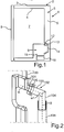
- Fig. 1 is shown in a simplified vertical sectional view of a household refrigerator 1, which is designed for storing and preserving food.
- That household refrigeration appliance 1 may be a refrigerator or a freezer or a fridge-freezer combination appliance his.
- the household refrigerating appliance 1 has a housing which has an outer housing 3 and an inner container 4.
- the outer housing 3 separate inner container 4 is received in the housing 3.
- a thermally insulating material 6 is introduced, for example, an insulating foam.
- the inner container 4 defines with its walls at least one receiving space 7, which may be, for example, a refrigerated compartment. Front side of the receiving space 7 is closed by a door 8 which is pivotally mounted on the housing 2.
- the household refrigerator 1 also has a machine room 9 in a lower rear area.
- a component of a refrigeration cycle of the household refrigerator 1 may be arranged.
- a component may for example be a compressor 10.
- a collecting tray 11 is also arranged in the machine room 9, which is preferably arranged adjacent to the compressor 10, for example, is arranged above the compressor 10.
- the inner container 1 has an integrally formed nozzle 12, so that in the receiving space 7 resulting liquid medium, such as water, from the receiving space 7 and from the inner container 4 can be derived out.
- the nozzle 12 is formed with a first end to a main body of the inner container 1 and formed with the opposite second, free end 19 cantilevered. This second end 19 represents an outlet or an end edge or an end edge of the nozzle 12.
- the domestic refrigerator 1 also has a drain pipe 13, which is a separate component to the nozzle 12 and which is directly coupled to the nozzle 12, as in Fig. 1 is shown.
- the household refrigerator 1 has a drain line 14, which is connected to the drain pipe 13 and a drain pipe 13 is a separate component.
- the drain line 14 opens into the machine room 9 and preferably into the collecting tray 11.
- the liquid accumulating in the receiving space 7 can thus be defined in the machine room 9 and preferably directed into the collecting tray 11, where the liquid due to the heat generated during operation of the compressor 10th can be evaporated.
- Fig. 3 is an embodiment of the drain pipe 13 is shown in a side view.
- the drain pipe 13 is in particular an angle pipe.
- the drain pipe 13 is preferably made in one piece, in particular as 2K injection molded component.
- This drain pipe 13 has a first pipe part 15, which here represents a first Rohhabites.
- the first tube part 15 has, in the direction of a longitudinal axis A, a first freely projecting tube dividing section 16 formed from an elastically deformable material.
- the material of the first pipe section end section here has a first elasticity.
- the first pipe part 15 has a second pipe section end section 17, which, viewed directly thereafter in the direction of the longitudinal axis A, opens onto the front, cantilevered first pipe section end section 16.
- the Rohr nameddabitese 16 and 17 are viewed in the direction of the longitudinal axis A contiguous to each other.
- the second pipe section end section 17 is formed with a different elasticity of its material to the first elasticity, in particular with a second elasticity which is greater for the first elasticity.
- the second pipe end portion 17 is dimensionally stable or dimensionally stable, and in particular made of plastic.
- the first pipe section end section 16 is preferably made of an elastomeric material, in particular completely as an elastomer.
- the drain pipe 13 also has a second pipe part 18, which here at an angle ⁇ to the first pipe part 15 opens. Viewed along the longitudinal axis A, the second tube part 18 forms a second tube section of the drainage tube 13.
- the material of the second tube part 18 is at least partially, in particular completely formed with a second elasticity, which is greater than the first elasticity.
- the second tube part 18 is preferably formed dimensionally stable or dimensionally stable and also made of plastic.
- the materials of the second pipe part 18 and the second pipe end portion 17 of the first pipe part 15 are made of the same plastic.
- the angle ⁇ is between 100 ° and 130 °.
- the first Rohr stolendabites 16 is considered here over its entire axial extent without additional stiffening sheath and / or formed without stiffening inner lining and thus designed in particular only as this preferably existing elastomeric material.
- the second pipe section end section 17 does not overlap the first pipe section end section 16 when viewed in the direction of the longitudinal axis A. at least not over the length provided for overlapping coupling with the stub 12.
- Fig. 4 a partial view of the household refrigerator 1 is shown.
- the inner container 4 is shown in the region of the nozzle 12, wherein here the drain pipe 15 is already shown in the coupled state with the nozzle 12.
- the nozzle 12 is arranged immersing in the first pipe section end portion 16 and immersing at most over such a length that corresponds to the extension of the first pipe section end portion 16 viewed in the direction of the longitudinal axis A.
- the axial overlap of the first pipe section end section 16 is formed such that the first pipe section end section 16 is designed to overlap both axially with the socket 12 and over the outlet or the second, free end of the socket 12, so that the first pipe section end portion 16 is also partially arranged non-overlapping with the nozzle 12.
- the preferably elastomeric part of the first pipe end portion 16 extends axially in the region of the free, second end 19 of the neck 12 then on both sides of this second end 19.
- the drain pipe 13 is an angle tube, that in addition to the above explanations or Instead, the area with the kink and thus the angle knee of a material with the first elasticity is formed, and thus is more elastic than the then adjacent on both sides further areas of the drain pipe 13.
- the on both sides Each of these flexible deformable center tube section subsequent areas are each completely stiffer.
- an adjoining area for example, as the above-explained first pipe part 15 is formed.
- the drain pipe 13 then has elastically deformable sections on two separate segments.
Landscapes
- Engineering & Computer Science (AREA)
- Chemical & Material Sciences (AREA)
- Combustion & Propulsion (AREA)
- Physics & Mathematics (AREA)
- Mechanical Engineering (AREA)
- Thermal Sciences (AREA)
- General Engineering & Computer Science (AREA)
- Removal Of Water From Condensation And Defrosting (AREA)
Priority Applications (1)
| Application Number | Priority Date | Filing Date | Title |
|---|---|---|---|
| PL18189556T PL3467410T3 (pl) | 2017-10-04 | 2018-08-17 | Urządzenie chłodnicze gospodarstwa domowego z jednostronną, elastyczną rurą odpływową |
Applications Claiming Priority (1)
| Application Number | Priority Date | Filing Date | Title |
|---|---|---|---|
| DE102017217628.8A DE102017217628A1 (de) | 2017-10-04 | 2017-10-04 | Haushaltskältegerät mit einem endseitig flexiblen Ablaufrohr |
Publications (2)
| Publication Number | Publication Date |
|---|---|
| EP3467410A1 true EP3467410A1 (fr) | 2019-04-10 |
| EP3467410B1 EP3467410B1 (fr) | 2022-03-16 |
Family
ID=63311822
Family Applications (1)
| Application Number | Title | Priority Date | Filing Date |
|---|---|---|---|
| EP18189556.6A Active EP3467410B1 (fr) | 2017-10-04 | 2018-08-17 | Appareil frigorifique domestique doté d'un tube d'évacuation dont l'extrémité est flexible |
Country Status (3)
| Country | Link |
|---|---|
| EP (1) | EP3467410B1 (fr) |
| DE (1) | DE102017217628A1 (fr) |
| PL (1) | PL3467410T3 (fr) |
Citations (9)
| Publication number | Priority date | Publication date | Assignee | Title |
|---|---|---|---|---|
| US2089231A (en) * | 1936-01-20 | 1937-08-10 | Migiel J Uline | Drain fixture for refrigerators |
| DE3735551C1 (de) * | 1987-10-21 | 1988-12-15 | Loh Kg Rittal Werk | Vorrichtung zum Entfernen von Tauwasser aus einem kompressorbetriebenen Kuehlgeraet |
| FR2769694A1 (fr) * | 1997-10-14 | 1999-04-16 | Valeo Climatisation | Boitier de dispositif de chauffage-climatisation pour vehicule automobile, comportant des moyens incorpores de recueil des condensats de l'evaporateur du climatiseur |
| JP3015715B2 (ja) * | 1995-06-30 | 2000-03-06 | 三洋電機株式会社 | 冷却貯蔵庫の排水装置 |
| JP2001330363A (ja) * | 2000-05-19 | 2001-11-30 | Hoshizaki Electric Co Ltd | 冷却貯蔵庫等の排水構造 |
| US20050210884A1 (en) * | 2004-03-22 | 2005-09-29 | Tuskiewicz George A | Portable cooled merchandizing unit |
| DE102008059085A1 (de) * | 2007-11-26 | 2009-07-09 | Behr Gmbh & Co. Kg | Klimaanlage für ein Kraftfahrzeug |
| JP2014001877A (ja) * | 2012-06-18 | 2014-01-09 | Mitsubishi Electric Corp | ショーケース |
| US20160377317A1 (en) * | 2015-06-23 | 2016-12-29 | Samsung Electronics Co., Ltd | Drain hose and air conditioner including the same |
-
2017
- 2017-10-04 DE DE102017217628.8A patent/DE102017217628A1/de not_active Withdrawn
-
2018
- 2018-08-17 PL PL18189556T patent/PL3467410T3/pl unknown
- 2018-08-17 EP EP18189556.6A patent/EP3467410B1/fr active Active
Patent Citations (9)
| Publication number | Priority date | Publication date | Assignee | Title |
|---|---|---|---|---|
| US2089231A (en) * | 1936-01-20 | 1937-08-10 | Migiel J Uline | Drain fixture for refrigerators |
| DE3735551C1 (de) * | 1987-10-21 | 1988-12-15 | Loh Kg Rittal Werk | Vorrichtung zum Entfernen von Tauwasser aus einem kompressorbetriebenen Kuehlgeraet |
| JP3015715B2 (ja) * | 1995-06-30 | 2000-03-06 | 三洋電機株式会社 | 冷却貯蔵庫の排水装置 |
| FR2769694A1 (fr) * | 1997-10-14 | 1999-04-16 | Valeo Climatisation | Boitier de dispositif de chauffage-climatisation pour vehicule automobile, comportant des moyens incorpores de recueil des condensats de l'evaporateur du climatiseur |
| JP2001330363A (ja) * | 2000-05-19 | 2001-11-30 | Hoshizaki Electric Co Ltd | 冷却貯蔵庫等の排水構造 |
| US20050210884A1 (en) * | 2004-03-22 | 2005-09-29 | Tuskiewicz George A | Portable cooled merchandizing unit |
| DE102008059085A1 (de) * | 2007-11-26 | 2009-07-09 | Behr Gmbh & Co. Kg | Klimaanlage für ein Kraftfahrzeug |
| JP2014001877A (ja) * | 2012-06-18 | 2014-01-09 | Mitsubishi Electric Corp | ショーケース |
| US20160377317A1 (en) * | 2015-06-23 | 2016-12-29 | Samsung Electronics Co., Ltd | Drain hose and air conditioner including the same |
Also Published As
| Publication number | Publication date |
|---|---|
| EP3467410B1 (fr) | 2022-03-16 |
| PL3467410T3 (pl) | 2022-06-27 |
| DE102017217628A1 (de) | 2019-04-04 |
Similar Documents
| Publication | Publication Date | Title |
|---|---|---|
| EP2596309B1 (fr) | Appareil réfrigérant, notamment appareil réfrigérant ménager | |
| EP2746703A2 (fr) | Porte d'appareil frigorifique ménager avec poignée repositionnable sans démontage, appareil frigorifique ménager et procédé de positionnement d'une poignée | |
| DE102017207012A1 (de) | Lager für eine Lenkspindel und Lenksäule für ein Kraftfahrzeug | |
| EP3080529B1 (fr) | Appareil frigorifique domestique ayant un compartiment de machinerie avec un bac de support sur lequel un autre composant est fixé | |
| EP3283831B1 (fr) | Porte pour un appareil frigorifique ménager avec une baguette de bord clipsé, appareil frigorifique ménager et methode pour fabriquer une porte | |
| EP3467410A1 (fr) | Appareil frigorifique domestique doté d'un tube d'évacuation dont l'extrémité est flexible | |
| DE102019218222A1 (de) | Haushaltskühlgerät mit einem Vorsprung als Kondenswasser-Tropfleiste in einer Wand eines Eisbereiters | |
| DE69604265T2 (de) | Kühlgerät mit einer Einrichtung zum Abführen des Tauwassers | |
| EP3147604B1 (fr) | Procédé de production d'un réfrigérateur ménager et réfrigérateur ménager | |
| EP3894761B1 (fr) | Machine frigorifique et appareil frigorifique utilisant celle-ci | |
| EP4330608A1 (fr) | Appareil frigorifique électroménager doté d'une paroi arrière spécifique d'espace machine, et procédé d'assemblage | |
| EP1929219B1 (fr) | Appareil frigorifique a evacuation d'eau | |
| WO2010133433A1 (fr) | Boîtier d'appareil frigorifique comportant un passage d'équilibrage de pression | |
| EP3421911A1 (fr) | Appareil frigorifique électroménager doté d'un module fonctionnel spécifique disposé sur une traverse de mousse ainsi que procédé de montage d'un module fonctionnel | |
| DE102015006912B4 (de) | Kühl- und/oder Gefriergerät | |
| EP3680405A1 (fr) | Caissons encastrables | |
| DE102019216651A1 (de) | Kältegerät und Leitungsdurchführung dafür | |
| DE102012223545A1 (de) | Wandung für ein Haushaltskältegerät mit einem viereckigen Trägerrahmen für einen thermischen Isolationskörper sowie Haushaltskältegerät | |
| DE202008001115U1 (de) | Tauwasserablauf für ein Kühl- und/oder Gefriergerät sowie Kühl- und/oder Gefriergerät mit Tauwasserablauf | |
| DE202005019586U1 (de) | Kühlgerät | |
| DE102016212457A1 (de) | Bedienvorrichtung mit einem Bedienelement und einem diesen umgebenden Rahmen und einem Langloch als Mittel zur Befestigung | |
| WO2023030959A1 (fr) | Porte dotée d'un élément d'étanchéité disposé de façon spécifique, et appareil ménager | |
| DE102007017283A1 (de) | Vorrichtung zum Sperren eines Fluiddurchtritts durch ein rohrförmiges Teil mittels eines Rückschlagventils, insbesondere in einem Hausgerät | |
| DE102022204508A1 (de) | Kraftfahrzeuggetriebe mit einem Drehmomentwandler | |
| WO2017063863A1 (fr) | Appareil menager à joint d'étanchéite en mousse et procédé de fabrication d'un ensemble correspondant |
Legal Events
| Date | Code | Title | Description |
|---|---|---|---|
| PUAI | Public reference made under article 153(3) epc to a published international application that has entered the european phase |
Free format text: ORIGINAL CODE: 0009012 |
|
| STAA | Information on the status of an ep patent application or granted ep patent |
Free format text: STATUS: THE APPLICATION HAS BEEN PUBLISHED |
|
| AK | Designated contracting states |
Kind code of ref document: A1 Designated state(s): AL AT BE BG CH CY CZ DE DK EE ES FI FR GB GR HR HU IE IS IT LI LT LU LV MC MK MT NL NO PL PT RO RS SE SI SK SM TR |
|
| AX | Request for extension of the european patent |
Extension state: BA ME |
|
| STAA | Information on the status of an ep patent application or granted ep patent |
Free format text: STATUS: REQUEST FOR EXAMINATION WAS MADE |
|
| 17P | Request for examination filed |
Effective date: 20191010 |
|
| RBV | Designated contracting states (corrected) |
Designated state(s): AL AT BE BG CH CY CZ DE DK EE ES FI FR GB GR HR HU IE IS IT LI LT LU LV MC MK MT NL NO PL PT RO RS SE SI SK SM TR |
|
| STAA | Information on the status of an ep patent application or granted ep patent |
Free format text: STATUS: EXAMINATION IS IN PROGRESS |
|
| 17Q | First examination report despatched |
Effective date: 20201021 |
|
| GRAP | Despatch of communication of intention to grant a patent |
Free format text: ORIGINAL CODE: EPIDOSNIGR1 |
|
| STAA | Information on the status of an ep patent application or granted ep patent |
Free format text: STATUS: GRANT OF PATENT IS INTENDED |
|
| INTG | Intention to grant announced |
Effective date: 20211025 |
|
| GRAS | Grant fee paid |
Free format text: ORIGINAL CODE: EPIDOSNIGR3 |
|
| GRAA | (expected) grant |
Free format text: ORIGINAL CODE: 0009210 |
|
| STAA | Information on the status of an ep patent application or granted ep patent |
Free format text: STATUS: THE PATENT HAS BEEN GRANTED |
|
| AK | Designated contracting states |
Kind code of ref document: B1 Designated state(s): AL AT BE BG CH CY CZ DE DK EE ES FI FR GB GR HR HU IE IS IT LI LT LU LV MC MK MT NL NO PL PT RO RS SE SI SK SM TR |
|
| REG | Reference to a national code |
Ref country code: GB Ref legal event code: FG4D Free format text: NOT ENGLISH |
|
| REG | Reference to a national code |
Ref country code: CH Ref legal event code: EP Ref country code: DE Ref legal event code: R096 Ref document number: 502018009089 Country of ref document: DE |
|
| REG | Reference to a national code |
Ref country code: IE Ref legal event code: FG4D Free format text: LANGUAGE OF EP DOCUMENT: GERMAN |
|
| REG | Reference to a national code |
Ref country code: AT Ref legal event code: REF Ref document number: 1476168 Country of ref document: AT Kind code of ref document: T Effective date: 20220415 |
|
| REG | Reference to a national code |
Ref country code: LT Ref legal event code: MG9D |
|
| REG | Reference to a national code |
Ref country code: NL Ref legal event code: MP Effective date: 20220316 |
|
| PG25 | Lapsed in a contracting state [announced via postgrant information from national office to epo] |
Ref country code: SE Free format text: LAPSE BECAUSE OF FAILURE TO SUBMIT A TRANSLATION OF THE DESCRIPTION OR TO PAY THE FEE WITHIN THE PRESCRIBED TIME-LIMIT Effective date: 20220316 Ref country code: RS Free format text: LAPSE BECAUSE OF FAILURE TO SUBMIT A TRANSLATION OF THE DESCRIPTION OR TO PAY THE FEE WITHIN THE PRESCRIBED TIME-LIMIT Effective date: 20220316 Ref country code: NO Free format text: LAPSE BECAUSE OF FAILURE TO SUBMIT A TRANSLATION OF THE DESCRIPTION OR TO PAY THE FEE WITHIN THE PRESCRIBED TIME-LIMIT Effective date: 20220616 Ref country code: LT Free format text: LAPSE BECAUSE OF FAILURE TO SUBMIT A TRANSLATION OF THE DESCRIPTION OR TO PAY THE FEE WITHIN THE PRESCRIBED TIME-LIMIT Effective date: 20220316 Ref country code: HR Free format text: LAPSE BECAUSE OF FAILURE TO SUBMIT A TRANSLATION OF THE DESCRIPTION OR TO PAY THE FEE WITHIN THE PRESCRIBED TIME-LIMIT Effective date: 20220316 Ref country code: BG Free format text: LAPSE BECAUSE OF FAILURE TO SUBMIT A TRANSLATION OF THE DESCRIPTION OR TO PAY THE FEE WITHIN THE PRESCRIBED TIME-LIMIT Effective date: 20220616 |
|
| PG25 | Lapsed in a contracting state [announced via postgrant information from national office to epo] |
Ref country code: LV Free format text: LAPSE BECAUSE OF FAILURE TO SUBMIT A TRANSLATION OF THE DESCRIPTION OR TO PAY THE FEE WITHIN THE PRESCRIBED TIME-LIMIT Effective date: 20220316 Ref country code: GR Free format text: LAPSE BECAUSE OF FAILURE TO SUBMIT A TRANSLATION OF THE DESCRIPTION OR TO PAY THE FEE WITHIN THE PRESCRIBED TIME-LIMIT Effective date: 20220617 Ref country code: FI Free format text: LAPSE BECAUSE OF FAILURE TO SUBMIT A TRANSLATION OF THE DESCRIPTION OR TO PAY THE FEE WITHIN THE PRESCRIBED TIME-LIMIT Effective date: 20220316 |
|
| PG25 | Lapsed in a contracting state [announced via postgrant information from national office to epo] |
Ref country code: NL Free format text: LAPSE BECAUSE OF FAILURE TO SUBMIT A TRANSLATION OF THE DESCRIPTION OR TO PAY THE FEE WITHIN THE PRESCRIBED TIME-LIMIT Effective date: 20220316 |
|
| PG25 | Lapsed in a contracting state [announced via postgrant information from national office to epo] |
Ref country code: SM Free format text: LAPSE BECAUSE OF FAILURE TO SUBMIT A TRANSLATION OF THE DESCRIPTION OR TO PAY THE FEE WITHIN THE PRESCRIBED TIME-LIMIT Effective date: 20220316 Ref country code: SK Free format text: LAPSE BECAUSE OF FAILURE TO SUBMIT A TRANSLATION OF THE DESCRIPTION OR TO PAY THE FEE WITHIN THE PRESCRIBED TIME-LIMIT Effective date: 20220316 Ref country code: RO Free format text: LAPSE BECAUSE OF FAILURE TO SUBMIT A TRANSLATION OF THE DESCRIPTION OR TO PAY THE FEE WITHIN THE PRESCRIBED TIME-LIMIT Effective date: 20220316 Ref country code: PT Free format text: LAPSE BECAUSE OF FAILURE TO SUBMIT A TRANSLATION OF THE DESCRIPTION OR TO PAY THE FEE WITHIN THE PRESCRIBED TIME-LIMIT Effective date: 20220718 Ref country code: ES Free format text: LAPSE BECAUSE OF FAILURE TO SUBMIT A TRANSLATION OF THE DESCRIPTION OR TO PAY THE FEE WITHIN THE PRESCRIBED TIME-LIMIT Effective date: 20220316 Ref country code: EE Free format text: LAPSE BECAUSE OF FAILURE TO SUBMIT A TRANSLATION OF THE DESCRIPTION OR TO PAY THE FEE WITHIN THE PRESCRIBED TIME-LIMIT Effective date: 20220316 Ref country code: CZ Free format text: LAPSE BECAUSE OF FAILURE TO SUBMIT A TRANSLATION OF THE DESCRIPTION OR TO PAY THE FEE WITHIN THE PRESCRIBED TIME-LIMIT Effective date: 20220316 |
|
| PGFP | Annual fee paid to national office [announced via postgrant information from national office to epo] |
Ref country code: IT Payment date: 20220831 Year of fee payment: 5 |
|
| PG25 | Lapsed in a contracting state [announced via postgrant information from national office to epo] |
Ref country code: IS Free format text: LAPSE BECAUSE OF FAILURE TO SUBMIT A TRANSLATION OF THE DESCRIPTION OR TO PAY THE FEE WITHIN THE PRESCRIBED TIME-LIMIT Effective date: 20220716 Ref country code: AL Free format text: LAPSE BECAUSE OF FAILURE TO SUBMIT A TRANSLATION OF THE DESCRIPTION OR TO PAY THE FEE WITHIN THE PRESCRIBED TIME-LIMIT Effective date: 20220316 |
|
| REG | Reference to a national code |
Ref country code: DE Ref legal event code: R097 Ref document number: 502018009089 Country of ref document: DE |
|
| PLBE | No opposition filed within time limit |
Free format text: ORIGINAL CODE: 0009261 |
|
| STAA | Information on the status of an ep patent application or granted ep patent |
Free format text: STATUS: NO OPPOSITION FILED WITHIN TIME LIMIT |
|
| PG25 | Lapsed in a contracting state [announced via postgrant information from national office to epo] |
Ref country code: DK Free format text: LAPSE BECAUSE OF FAILURE TO SUBMIT A TRANSLATION OF THE DESCRIPTION OR TO PAY THE FEE WITHIN THE PRESCRIBED TIME-LIMIT Effective date: 20220316 |
|
| 26N | No opposition filed |
Effective date: 20221219 |
|
| PG25 | Lapsed in a contracting state [announced via postgrant information from national office to epo] |
Ref country code: SI Free format text: LAPSE BECAUSE OF FAILURE TO SUBMIT A TRANSLATION OF THE DESCRIPTION OR TO PAY THE FEE WITHIN THE PRESCRIBED TIME-LIMIT Effective date: 20220316 |
|
| PG25 | Lapsed in a contracting state [announced via postgrant information from national office to epo] |
Ref country code: MC Free format text: LAPSE BECAUSE OF FAILURE TO SUBMIT A TRANSLATION OF THE DESCRIPTION OR TO PAY THE FEE WITHIN THE PRESCRIBED TIME-LIMIT Effective date: 20220316 |
|
| REG | Reference to a national code |
Ref country code: CH Ref legal event code: PL |
|
| GBPC | Gb: european patent ceased through non-payment of renewal fee |
Effective date: 20220817 |
|
| PG25 | Lapsed in a contracting state [announced via postgrant information from national office to epo] |
Ref country code: LU Free format text: LAPSE BECAUSE OF NON-PAYMENT OF DUE FEES Effective date: 20220817 Ref country code: LI Free format text: LAPSE BECAUSE OF NON-PAYMENT OF DUE FEES Effective date: 20220831 Ref country code: CH Free format text: LAPSE BECAUSE OF NON-PAYMENT OF DUE FEES Effective date: 20220831 |
|
| REG | Reference to a national code |
Ref country code: BE Ref legal event code: MM Effective date: 20220831 |
|
| PG25 | Lapsed in a contracting state [announced via postgrant information from national office to epo] |
Ref country code: IE Free format text: LAPSE BECAUSE OF NON-PAYMENT OF DUE FEES Effective date: 20220817 Ref country code: FR Free format text: LAPSE BECAUSE OF NON-PAYMENT OF DUE FEES Effective date: 20220831 |
|
| PG25 | Lapsed in a contracting state [announced via postgrant information from national office to epo] |
Ref country code: BE Free format text: LAPSE BECAUSE OF NON-PAYMENT OF DUE FEES Effective date: 20220831 |
|
| PG25 | Lapsed in a contracting state [announced via postgrant information from national office to epo] |
Ref country code: GB Free format text: LAPSE BECAUSE OF NON-PAYMENT OF DUE FEES Effective date: 20220817 |
|
| PG25 | Lapsed in a contracting state [announced via postgrant information from national office to epo] |
Ref country code: HU Free format text: LAPSE BECAUSE OF FAILURE TO SUBMIT A TRANSLATION OF THE DESCRIPTION OR TO PAY THE FEE WITHIN THE PRESCRIBED TIME-LIMIT; INVALID AB INITIO Effective date: 20180817 |
|
| PG25 | Lapsed in a contracting state [announced via postgrant information from national office to epo] |
Ref country code: CY Free format text: LAPSE BECAUSE OF FAILURE TO SUBMIT A TRANSLATION OF THE DESCRIPTION OR TO PAY THE FEE WITHIN THE PRESCRIBED TIME-LIMIT Effective date: 20220316 |
|
| PG25 | Lapsed in a contracting state [announced via postgrant information from national office to epo] |
Ref country code: MK Free format text: LAPSE BECAUSE OF FAILURE TO SUBMIT A TRANSLATION OF THE DESCRIPTION OR TO PAY THE FEE WITHIN THE PRESCRIBED TIME-LIMIT Effective date: 20220316 |
|
| PG25 | Lapsed in a contracting state [announced via postgrant information from national office to epo] |
Ref country code: IT Free format text: LAPSE BECAUSE OF NON-PAYMENT OF DUE FEES Effective date: 20230817 |
|
| PG25 | Lapsed in a contracting state [announced via postgrant information from national office to epo] |
Ref country code: MT Free format text: LAPSE BECAUSE OF FAILURE TO SUBMIT A TRANSLATION OF THE DESCRIPTION OR TO PAY THE FEE WITHIN THE PRESCRIBED TIME-LIMIT Effective date: 20220316 |
|
| REG | Reference to a national code |
Ref country code: AT Ref legal event code: MM01 Ref document number: 1476168 Country of ref document: AT Kind code of ref document: T Effective date: 20230817 |
|
| PG25 | Lapsed in a contracting state [announced via postgrant information from national office to epo] |
Ref country code: AT Free format text: LAPSE BECAUSE OF NON-PAYMENT OF DUE FEES Effective date: 20230817 |
|
| PG25 | Lapsed in a contracting state [announced via postgrant information from national office to epo] |
Ref country code: AT Free format text: LAPSE BECAUSE OF NON-PAYMENT OF DUE FEES Effective date: 20230817 |
|
| PGFP | Annual fee paid to national office [announced via postgrant information from national office to epo] |
Ref country code: DE Payment date: 20250831 Year of fee payment: 8 |
|
| PGFP | Annual fee paid to national office [announced via postgrant information from national office to epo] |
Ref country code: TR Payment date: 20250808 Year of fee payment: 8 Ref country code: PL Payment date: 20250801 Year of fee payment: 8 |
|
| PGFP | Annual fee paid to national office [announced via postgrant information from national office to epo] |
Ref country code: AT Payment date: 20260410 Year of fee payment: 5 |