EP3468372B1 - Moulding device and method for moulding - Google Patents
Moulding device and method for moulding Download PDFInfo
- Publication number
- EP3468372B1 EP3468372B1 EP17732250.0A EP17732250A EP3468372B1 EP 3468372 B1 EP3468372 B1 EP 3468372B1 EP 17732250 A EP17732250 A EP 17732250A EP 3468372 B1 EP3468372 B1 EP 3468372B1
- Authority
- EP
- European Patent Office
- Prior art keywords
- moulding
- drum assembly
- peripheral surface
- moulding drum
- shoe member
- Prior art date
- Legal status (The legal status is an assumption and is not a legal conclusion. Google has not performed a legal analysis and makes no representation as to the accuracy of the status listed.)
- Active
Links
Images


Classifications
-
- A—HUMAN NECESSITIES
- A22—BUTCHERING; MEAT TREATMENT; PROCESSING POULTRY OR FISH
- A22C—PROCESSING MEAT, POULTRY, OR FISH
- A22C7/00—Apparatus for pounding, forming, or pressing meat, sausage-meat, or meat products
- A22C7/0023—Pressing means
- A22C7/003—Meat-moulds
- A22C7/0069—Pressing and moulding by means of a drum
-
- A—HUMAN NECESSITIES
- A22—BUTCHERING; MEAT TREATMENT; PROCESSING POULTRY OR FISH
- A22C—PROCESSING MEAT, POULTRY, OR FISH
- A22C7/00—Apparatus for pounding, forming, or pressing meat, sausage-meat, or meat products
-
- A—HUMAN NECESSITIES
- A22—BUTCHERING; MEAT TREATMENT; PROCESSING POULTRY OR FISH
- A22C—PROCESSING MEAT, POULTRY, OR FISH
- A22C7/00—Apparatus for pounding, forming, or pressing meat, sausage-meat, or meat products
- A22C7/0092—Apparatus for pounding, forming, or pressing meat, sausage-meat, or meat products with worms or other rotary mounted members
-
- A—HUMAN NECESSITIES
- A23—FOODS OR FOODSTUFFS; TREATMENT THEREOF, NOT COVERED BY OTHER CLASSES
- A23P—SHAPING OR WORKING OF FOODSTUFFS, NOT FULLY COVERED BY A SINGLE OTHER SUBCLASS
- A23P30/00—Shaping or working of foodstuffs characterised by the process or apparatus
- A23P30/10—Moulding
Definitions
- the present invention relates to a moulding device and a method for moulding food products from a mass of foodstuff which can be transferred by pumping, for example a mass of minced meat.
- Such a moulding device is known e.g. from WO2004002229 and WO2010110655 and WO2014148897 of the same applicant. These known moulding devices comprise:
- the mass feed device comprising the inlet member and shoe member, and possibly also a pump and a silo for receiving the mass of foodstuff, is supported by a stationary frame.
- the stationary frame is a fixed frame, and possibly the same stationary frame as the frame supporting the rotary bearing assembly.
- the shoe member is part of the mass feed device, it is supported by the stationary frame to absorb the outward force generated by the foodstuff.
- the mass feed device comprises a shoe member supported by a housing, which shoe member is designed to adapt to irregularities in the outer circumference of the drum, even when the drum is not perfectly cylindrical, so that loss of mass is limited and leakage during the application of a vacuum and/or pressure is avoided.
- the shoe member is flexible to a certain degree, so that it is able to follow any deviations.
- the shoe member comprises a flexible plate which is held against the peripheral surface under pressure produced by excess-pressure means.
- the excess-pressure means e.g. comprise at least one pressure cushion and a number of lamellae, which are positioned transversely with respect to the direction of rotation of the moulding drum assembly, and which are arranged between the pressure cushion and the plate.
- US 3490391 discloses a feeder which includes a pocketed rotor which continuously rotates and presents the pockets thereof first to an inlet of a housing in which the rotor is mounted for rotation and then to an outlet of that housing. Material is pulled into the pockets by a vacuum and compressed gasses are forced into the pockets to drive the material out of the pockets.
- WO 00/30458 A1 provides methods and moulding devices for moulding three-dimensional products from a mass of foodstuff which is suitable for human consumption.
- the method comprises filling a mould cavity with a portion of the mass under the influence of a filling pressure exerted on the mass and for a filling period via a filling opening associated with the mould cavity, closing the filling opening of the mould cavity and holding the mass in the mould cavity for a fixed period. Then, the mould cavity is opened and the moulded product is removed from the mould cavity.
- WO 98/12934 discloses a cooking aid having the shape of a pebble containing visual elements held together by a matrix made of fat and a dehydrated base.
- a disadvantage of the known shoe members supported by a stationary rigid frame or housing is that the generation of outward forces and absorption by the rigid frame results in a net force exerted onto the relatively weak moulding drum assembly, resulting in deformation of the moulding drum assembly, in particular of the rotation axis of the moulding drum assembly.
- the rotation axis When the moulding drum assembly is supported at one end, the rotation axis may be deformed to be angled downwards towards the non-supported end. In case of a moulding drum supported at both ends, the rotation axis may be bent downwards in the central part thereof.
- the aim of the present invention is to provide an alternative configuration.
- the moulding device comprises:
- a non-force transmitting flexible connection is provided between the shoe member and the inlet member, such that force transmittal from the shoe member to the inlet member is not possible.
- the moulding device comprises:
- the present invention further relates to a method for moulding food products from a mass of foodstuff which can be transferred by pumping, for example a meat mass of minced meat, wherein use is made of such a moulding device.
- the entire outward force generated by the foodstuff is counteracted by a counterforce element, instead of being absorbed by a fixed frame.
- the shoe member which is known per se, is according to the claimed invention part of the non-revolving component, which is concentrically supported by the moulding drum assembly adjacent and movable in a radial direction to the peripheral surface thereof, and hence no longer by the frame.
- a non-force transmitting flexible connection is provided between the shoe member and the inlet member, such that force transmittal of the outward force exerted by the pressurized foodstuff on the shoe member to the inlet member is not possible.
- the advantage of the configuration of the claimed invention is that there is no net force exerted onto the moulding drum assembly, resulting in a reduced load on the rotary bearing assemblies.
- the anti-torque member is provided to prevent rotation of the non-revolving component.
- the anti-torque member is provided between the non-revolving component and the stationary frame.
- the anti-torque member is provided between the non-revolving component and an alternative stationary element, such as a support onto which the moulding device is positioned, or part of the mass feed device which is provided stationary, e.g. a pump. It is noticed that no force transmittal of the outward force exerted by the pressurized foodstuff on the shoe member is possible via the anti-torque member.
- the shoe member and the counterforce element of the non-revolving component are interconnected at one end only, forming an essentially C-shaped non-revolving element.
- the shoe member and the counterforce element are interconnected at both ends to form a ring-shaped non-revolving component.
- the shoe member and counterforce element are interconnected to form the non-revolving component.
- the shoe member and counterforce element are directly connected.
- connectors are provided to connect the shoe member and the counterforce element to form the non-revolving component.
- one or more connection beams extending parallel to the drum rotation axis are provided to which one or more shoe members are connected on the one hand, and one or more counterforce element are connected on the other hand.
- the counterforce element is provided generally opposite the shoe member.
- the shoe member and the counterforce element are positioned radially opposite one another. This configuration is advantageous in view of the distribution of forces, but alternative configurations wherein the counterforce element is not provided radially opposite the shoe member are also within the scope of the present invention.
- An exemplary alternative configuration of the non-revolving component is horse-shoe shaped, with the shoe member centrally at the upper end thereof, while two counterforce elements are formed at the distal legs thereof, thus provided generally opposite but not radially opposite the shoe member.
- the shoe member and the counterforce element are positioned in line with each other, viewed in the direction of the rotation axis.
- account has to be taken of the discharge of the moulded food products, as generally the discharge takes place radially opposite the filling.
- the moulded food products can be discharged in the open end between the distal legs.
- the counterforce element is provided with a discharge opening for moulded products.
- the shoe member and the counterforce element are positioned offset, viewed in direction of the rotation direction.
- a connection beam or pin, parallel to the direction of the rotation axis may connect the offset shoe member(s) and counterforce element(s).
- the counterforce element can be positioned remote from a discharge region for discharging moulded food products.
- the non-revolving component comprises two counterforce elements, provided at opposed ends of the moulding drum assembly.
- the non-revolving component comprises multiple counterforce elements, equally distributed over the length of the revolving moulding drum assembly.
- a bearing is provided, e.g. a roller bearing, ball bearing or plain bearing with a lubricant.
- the bearing is pressurized, e.g. by a spring, to actively press the shoe member to adjoin the peripheral surface of the moulding drum assembly.
- the shoe member is designed to adapt to irregularities in the outer circumference of the drum, even when the drum is not perfectly cylindrical, so that loss of mass is limited and leakage during the application of a vacuum and/or pressure is avoided.
- Alternative pressure devices are also conceivable, such as the cushions and lamellae configuration of WO2004002229 .
- the shoe member is flexible to a certain degree, so that it is able to follow any deviations. It is conceivable that the shoe member comprises a flexible plate which is held against the peripheral surface, and is pressurized by the bearing between the counterforce element and the moulding drum assembly.
- the non-revolving component further comprises a moulding drum assembly engaging scraper, provided after discharge of a moulded product seen in direction of rotation, to scrape foodstuff remnants from the peripheral surface.
- the frame of the moulding device of the invention is provided stationary, i.e. fixed to a support.
- the drive motor is generally supported by the frame, or provided in the frame.
- the moulding drum assembly is driven by means of the drive motor.
- a rotary bearing assembly e.g. comprising roller bearings, is supported by the frame, and provided between the frame and a revolving moulding drum assembly.
- the moulding drum assembly comprises a rotating shaft, connected to the drive motor to allow rotation of the moulding drum assembly.
- the rotating shaft is rotatably supported relative to the frame via the rotary bearing assembly.
- a rotating bearing is provided adjacent the drive motor in the frame. It is both conceivable that the rotating shaft is supported at one end only, or at both ends, or possibly also at an intermediate area.
- a stationary spindle is fixed to the frame, and the rotary bearing assembly is provided between the spindle and the moulding drum assembly.
- the drive motor allows the moulding drum assembly to revolve about the spindle.
- the rotary bearing assembly rotatably supports the moulding drum assembly about a longitudinal drum rotation axis.
- the rotation axis is substantially horizontal. Possibly, the rotation axis may be slightly angled with respect to the horizontal. In particular, it is conceivable that the rotation axis is slightly bended.
- the rotation axis When the moulding drum assembly is supported at one end, the rotation axis may be angled downwards towards the non-supported end. In case of a moulding drum supported at both ends, the rotation axis may be bent downwards in the central part thereof.
- the moulding drum assembly has a peripheral surface in which one or more mould cavities are provided.
- the moulding drum assembly has a cylindrical outer contour with a peripheral surface, in which generally multiple mould cavities are provided.
- multiple mould cavities are arranged in the peripheral surface in a mould cavities pattern, e.g. an array of mould cavities.
- a row of cavities comprises cavities may be arranged at multiple longitudinal positions when seen in longitudinal (axial) direction of the moulding drum assembly, i.e. in the direction of the rotation axis.
- multiple rows of mould cavities are provided, e.g. 5-10 rows.
- the filling openings of a row of cavities come into communication with a filling mouth of the shoe member.
- a series of cavities comprises cavities may be arranged at multiple peripheral positions when seen in peripheral (circumferential) direction of the moulding drum assembly.
- multiple series of mould cavities extend in the peripheral direction, wherein said series extend substantially parallel to and at a distance from one another, viewed in the direction of the rotation axis.
- Each series may comprise multiple mould cavities which are at a distance from one another, viewed in the peripheral direction of the peripheral surface of the moulding drum assembly.
- the mould cavities of multiple series are aligned in rows.
- the moulding device further comprises a mass feed device arranged in a filling position with respect to the peripheral surface of the moulding drum. In operation, the mass feed device feeds a pressurized mass of foodstuff to the one or more mould cavities.
- the mass feed device comprises an inlet member for feeding a pressurized mass of foodstuff. Possibly, the mass feed device further comprises a pump to generate the pressurized mass of foodstuff, and a silo for receiving the mass of foodstuff.
- the stationary frame is a fixed frame, and possibly the same stationary frame as the frame supporting the rotary bearing assembly.
- the mass feed device further comprises a shoe member in communication with the inlet member, comprising a filling mouth which adjoins the peripheral surface of the moulding drum assembly.
- a shoe member comprises multiple filling mouth.
- the shoe member is supported by the moulding drum assembly.
- a non-force transmitting flexible connection is provided between the shoe member and the inlet member, such that force transmittal from the shoe member to the inlet member is not possible.
- a flexible connection is e.g. formed by a flexible hose.
- the mass feed device further comprises a distributor between the shoe member and the inlet member, wherein the inlet member is provided adjacent a pump.
- the flexible connection may be provided between the shoe member and the distributor, or between the distributor and the inlet member.
- a single shoe member is provided extending over the longitudinal length of the peripheral surface of the moulding drum assembly. As such, it is possible that a single shoe member is adapted to come into communication with one row of cavities at the time.
- the non-revolving component comprises multiple shoe members, provided substantially parallel to and adjacent one another, viewed in the direction of the rotation axis, each shoe member having a filling mouth adjoining an associated section of the peripheral surface (63) of the moulding drum assembly in which a series of cavities is arranged at multiple peripheral positions when seen in peripheral direction of the moulding drum assembly.
- the filling mouth of each shoe member is preferably provided adjacent one or two series of cavities, which move past the associated shoe member during rotation of the moulding drum assembly come into communication with said associated shoe member in order to fill said cavities of said series with the foodstuff as they move past.
- the multiple shoe members are provided floating in the direction of the rotation axis, such that each shoe member is free to align itself relative to the moulding drum assembly. This may e.g. compensate for misalignment caused by fitting errors and thermal expansion or contraction.
- the peripheral surface of the moulding drum assembly is embodied as a profiled peripheral surface having a shaping profile which comprises, for each series of cavities arranged at multiple peripheral positions when seen in peripheral direction of the moulding drum assembly, projections between multiple pairs of successive cavities of said series and/or one or more peripheral grooves which extend in the peripheral direction between and through the successive cavities of said series.
- an inner side of each shoe member which adjoins an associated section of the peripheral surface of the moulding drum assembly is embodied as a profiled inner side having a profile which section comprises, for each series of cavities, one or more grooves extending in the peripheral direction and/or ribs extending in the peripheral direction, which grooves and/or ribs are in meshing engagement with the profiled peripheral surface of said section of the moulding drum.
- each floating shoe member is able to align itself relative to a section of the moulding drum via the meshing configuration.
- the present invention further relates to a non-revolving component, adapted to be concentrically supported by a moulding drum assembly adjacent and movable in a radial direction to a peripheral surface thereof, comprising:
- the non-revolving component further comprises connection beams extending parallel to the drum rotation axis, to which one or more shoe members are connected adjacent filling openings in the peripheral surface of the moulding drum assembly, and to which one or more moulding drum assembly engaging counterforce elements are connected.
- connection beams extending parallel to the drum rotation axis, to which one or more shoe members are connected adjacent filling openings in the peripheral surface of the moulding drum assembly, and to which one or more moulding drum assembly engaging counterforce elements are connected.
- two moulding drum assembly engaging counterforce elements are provided at the ends of the connection beams adjacent the peripheral surface at the ends of the moulding drum assembly, preferably remote from the filling openings.
- the present invention further relates to the combination of the above-described non-revolving component and an anti-torque member to prevent rotation of the non-revolving component.
- the present invention further relates to the combination of the above-described non-revolving component and a revolving moulding drum assembly having a peripheral surface in which one or more mould cavities are provided, wherein the cavities each define a filling opening in the peripheral surface.
- the present invention also relates to the combination of a revolving moulding drum assembly and an associated non-revolving component for use in a moulding device for the moulding of food products, wherein the drum assembly has a rotation axis and a peripheral surface in which mould cavities are provided, wherein the cavities each define a filling opening in the peripheral surface, and wherein said moulding drum comprises first and second end parts, e.g.
- each of said first and second bearing comprises or is formed by a set of two rollers engaging a respective rotation symmetrical surface at a respective axial end of the drum, the two rollers of a set being spaced apart in circumferential direction.
- the present invention further relates to a non-revolving component for use in a moulding device according to any of claims 1-10.
- the moulding device 10 comprises a revolving moulding drum assembly 1 and a stationary frame 2.
- stationary frame is provided with wheels so as to be transportable, e.g. for cleaning purposes.
- the wheels are fixed such that frame 2 is stationary.
- a drive motor (not shown) is provided to drive the moulding drum assembly 1.
- the shown revolving moulding drum assembly 1 comprises a rotating shaft 7, rotatably supported relative to the frame 2 via a rotary bearing assembly 6, so as to rotatably support the moulding drum assembly 1 about a longitudinal drum rotation axis RA.
- Revolving moulding drum assembly 1 has a peripheral surface 3 in which multiple mould cavities 4 are provided, wherein the cavities each define a filling opening in the peripheral surface.
- the mould cavities are arranged in an array of parallel rows, here 5-6, extending in the direction of the rotation axis, and parallel series, here 7, extending in the peripheral direction.
- Moulding device 10 further comprise a mass feed device 15 arranged in a filling position with respect to the peripheral surface of the moulding drum assembly.
- the mass feed device 15 comprises a pump unit 16 to generate the pressurized mass of foodstuff, and a silo 17 for receiving the mass of foodstuff. These parts of the mass feed device are supported by a stationary frame 20.
- the mass feed device 15 further comprises an inlet member 18 for feeding a pressurized mass of foodstuff, and a shoe member 19 in communication with the inlet member 18.
- the shoe member 19 comprises a filling mouth (not visible) which adjoins the peripheral surface of the moulding drum assembly in such a way that the filling opening of the one or more mould cavities which move past during rotation of the moulding drum assembly come into communication with said filling mouth in order to fill said cavities with the foodstuff as they move past.
- the pressurized mass of foodstuff introduced into a mould cavity causes an outward force onto said shoe member 19.
- the moulded food products are discharged via a discharge conveyor 8.
- the moulding device 10 further comprises a non-revolving component 25, concentrically supported by the moulding drum assembly 1 adjacent to and movable in a radial direction to the peripheral surface 3 thereof.
- Non-revolving component 25 comprises the shoe member 19 and interconnected moulding drum assembly engaging counterforce elements 26a, 26b, 26c, to counteract the entire outward force exerted by the pressurized foodstuff on the shoe member.
- counterforce elements are provided, at opposite ends of the moulding drum assembly 1 and at a central part thereof.
- the mould cavities are here provided between the counterforce elements.
- the counterforce elements are provided radially opposite the shoe member, i.e. in the shown embodiment a segment with a counterforce element and the shoe member form a closed ring in cross-section.
- anti-torque member 27 is provided to prevent rotation of the non-revolving component 25.
- anti-torque member 27 is embodied as a rod mounted to shoe member 19, which is provided with a slit for receiving a frame mounted pin 28, mounted onto stationary frame 2. The slit does not allow the non-revolving component 25 to rotate, but does allow flexibility in the radial direction.
- Hose 21 provided between shoe member 19 and inlet member 18 is provided as a non-force transmitting flexible connection between the shoe member 19 and the inlet member 18, such that force transmittal from the shoe member to the inlet member is not possible.
- the moulding device 30 comprises a frame 32, which is provided with wheels so as to be transportable between a moulding location and a remote location, e.g. for storage or cleaning. During moulding food products, the frame 32 is provided stationary.
- frame 32 supports a drive motor 35 controllable by a control device 39 to drive moulding drum assembly 31.
- a rotary bearing assembly supported by the stationary frame and rotatably supporting the moulding drum assembly about a longitudinal drum rotation axis RA.
- Revolving moulding drum assembly 31 has a peripheral surface in which one or more mould cavities are provided, neither of which is visible in the shown embodiment.
- the cavities each define a filling opening in the peripheral surface.
- the moulding device 30 further comprises a mass feed device 45 arranged in a filling position with respect to the peripheral surface of the moulding drum assembly 31.
- the mass feed device 45 comprises a pump unit 46 and a silo 47 supported by a frame 50, which in the shown embodiment is provided movable on wheels. During moulding the wheels are fixed such that frame 50 is stationary.
- the mass feed device further comprises an inlet member 48 for feeding a pressurized mass of foodstuff to a filling mouth (not visible) of a shoe member 49. in such a way that the filling opening of the one or more mould cavities which move past during rotation of the moulding drum assembly come into communication with said filling mouth in order to fill said cavities with the foodstuff as they move past..
- shoe member 49 adjoins the peripheral surface of the moulding drum assembly 31.
- the shoe member 49 is, according to the present invention, part of non-revolving component 55, concentrically supported by the moulding drum assembly 31 adjacent and movable in a radial direction to the peripheral surface thereof.
- the pressurized mass of foodstuff introduced into a mould cavity causes an outward force onto said shoe member 49.
- said outward force is counteracted by an interconnected moulding drum assembly engaging counterforce element 56, which is connected to the shoe member 49 to form a closed ring-shaped non-revolving component 25.
- counterforce element one or more discharge openings (not visible) are provided to discharge moulded products onto discharge belt 38.
- An anti-torque member 57 comprising a hook connected to the non-revolving component 55 and a pin connected to the frame 32, here the drive motor 35, to prevent the non-revolving component 55 from rotating together with the moulding drum assembly 31.
- the hook is designed to allow some radial movement of the non-revolving component with respect to the pin.
- a non-force transmitting flexible connection 51 is provided between shoe member 49 and inlet member 48, such that shoe member 49 is provided telescopically with respect to the inlet member 48, allowing flexibility of the shoe member 49 with respect to the inlet member 48.
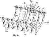
- a third embodiment is shown of a revolving moulding drum assembly 61, rotatable about rotation axis RA, and a non-revolving component 85, which is shown per se in fig. 3c .
- the revolving moulding drum assembly 61 has a peripheral surface 63 in which multiple mould cavities 64 are provided.
- the cavities 64 each define a filling opening in the peripheral surface.
- the peripheral surface 63 of the moulding drum assembly 61 is embodied as a profiled peripheral surface.
- the peripheral surface could be entirely cylindrical with a constant diameter of its axial length.
- the cavities 64 are arranged in 14 series, at different peripheral positions when seen in peripheral direction of the moulding drum assembly.
- the cavities are, in this example, also arranged in 8 adjacent and parallel axial rows, when seen in the direction of the rotation axis RA.
- the cavities could be arranged in helical rows or in staggered rows as is known in the art.
- the peripheral surface 63 has a non-cylindrical shaping profile which comprises, for each peripheral series of cavities 64 arranged at multiple peripheral positions when seen in peripheral direction of the moulding drum assembly, projections 63p. each Projection 63p is located between a pair of successive cavities 64 of said series. The projections 63p of a series protrude relative to a smaller diameter surface ring area 63g which extends in the peripheral direction about the drum. Between neighboring series of cavities 64 a surface ring area 63g is located.
- Non-revolving component 85 is concentrically supported by the moulding drum assembly 31 adjacent and movable in a radial direction to the peripheral surface 63 thereof.
- it comprises multiple, here 7 shoe members 79, provided substantially parallel to and adjacent one another, viewed in the direction of the rotation axis.
- Each shoe member comprises a filling mouth which is in communication with an inlet member, here not shown, via a distributor 81.
- Each filling mouth 80 adjoins an associated section of the peripheral surface 63 of the moulding drum assembly in such a way that the filling openings of two mould cavities of adjacent series of mould cavities 64 which move past during rotation of the moulding drum assembly come into communication with said filling mouth in order to fill said cavities with the foodstuff as they move past.
- the multiple shoe members 79 are provided floating in the direction of the rotation axis RA, such that each shoe member 79 is free to align itself relative to the moulding drum assembly, in particular relative to the projections 63p that correspond to a series of cavities 64, e.g. each shoe member 79 belonging to a single corresponding series of cavities 64.
- an inner side 79i of each shoe member 79 which adjoins an associated section of the peripheral surface 63 of the moulding drum assembly is embodied as a profiled inner side having a profile which section comprises, for each series of cavities, one or more (here two as best seen in figure 5 ) grooves 79a extending in the peripheral direction and ribs 79b extending in the peripheral direction, which grooves 79a and ribs 79b are in meshing engagement with the profiled peripheral surface 63 of said section of the moulding drum.
- the meshing engagement may include some play between the shoe member 79 and the drum surface 63 and projections 64 thereof.
- a not-shown anti-torque member is provided to prevent rotation of the non-revolving component 85, which is advantageously connected to a stationary frame such that some radial flexibility is allowed.
- the non-revolving component 85 may comprise one or more connection beams 85c and 85c', extending parallel to the drum rotation axis RA.
- the 7 shoe members 79 are connected to this connection beams, in operation adjacent filling openings in the peripheral surface of the moulding drum assembly.
- one or more moulding drum assembly engaging counterforce elements 86 may be connected to these connection beams 85c and 85c', extending remote from the filling openings, to counteract the outward force exerted by the pressurized foodstuff on the shoe member.
- each counterforce element 86 is positioned radially opposite a corresponding shoe member, so that a pair of a shoe member and counterforce element forms an assembly that encircles the drum, viewed in the direction of the rotation axis RA.
- Each assembly of shoe member and counterforce element may be separate from neigbouring such assemblies if desired, or they may be interconnected via said one or more connection beams.
- two counterforce elements 86 are positioned opposite each shoe member 79. Between two counterforce elements 86 is a discharge opening 89 for moulded products.
- the non-revolving component 85 comprises mounting tools 86a, to individually mount each shoe member 79 to the connection beam 85c'. This allows an expedient exchange of shoe members 79.
- mounting tool 86a and shoe member 79 is shown in detail.
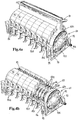
- a fourth embodiment of part of a moulding device is partially shown.
- the shoe member 79 and mounting tool 86a of this fourth embodiment are the same as that of the third embodiment, and is thus not described in further detail.
- the same reference numerals have been used.
- the non-revolving component comprises a connection beam 85c', extending parallel to the drum rotation axis RA, to which the mounting tools 86a of multiple shoe members 79 are connected adjacent filling openings in the peripheral surface of the moulding drum assembly.
- connection beam 90a is part of a connection subframe 90, to which also mounting tools 86a are mounted.
- connection subframe 90 at the end parts of the moulding drum, are two moulding drum assembly engaging counterforce elements 90c connected, adjacent the peripheral surface at the ends of the moulding drum assembly, remote from the filling openings.
- bearings 95 are provided between the counterforce elements 90c and the moulding drum assembly 61. It is illustrated that the bearings 95 here comprise at each axial end of the drum a set of rollers 95, that roll on an axial end part 63h of the drum. As is preferred this end part 63h has a diameter equal or greater than the diameter of the drum surface provided with cavities 64, e.g. greater than the diameter defined by projections 63p of such a drum type.
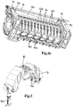
- FIGS. 4a-c illustrate an example of a combination of a revolving moulding drum assembly and an associated non-revolving component for use in a moulding device for the moulding of food products.
- the drum assembly has a rotation axis and a peripheral surface in which mould cavities are provided, wherein the cavities each define a filling opening in the peripheral surface.
- the moulding drum comprises first and second end parts, here each embodied as a rotation symmetrical surface 63h, at opposite axial ends of the peripheral surface in which mould cavities 64 are provided.
- the non-revolving component has a connection subframe with a first counterforce element 90c and a second counterforce element 90c at axial ends thereof.
- the subframe further comprises a first beam 90d along one side of the drum and a second beam 90e along the opposite side of the drum.
- the first counterforce element 90c cooperates with the first end part 63h via a first bearing, here via two rollers that roll over a rotation symmetrical surface 63h of the drum.
- the second counterforce element 90c cooperates with the second end part 63h via a second bearing, here via two rollers 95 that roll over a rotation symmetrical surface 63h.
- the subframe 90 carries the shoe members 79.
- one end of a semi-circular shoe member 79 is pivotally mounted to beam 90e, e.g. so as to allow for floating motion in direction of the beam, with the other end of the shoe member 79 being connected to the other beam 90d via a mounting tool 86a, e.g. so as to set a desired play between the shoe member 79 and the drum surface.
Landscapes
- Engineering & Computer Science (AREA)
- Life Sciences & Earth Sciences (AREA)
- Food Science & Technology (AREA)
- Wood Science & Technology (AREA)
- Zoology (AREA)
- Manufacturing & Machinery (AREA)
- Chemical & Material Sciences (AREA)
- Polymers & Plastics (AREA)
- Formation And Processing Of Food Products (AREA)
- Mechanical Engineering (AREA)
- Robotics (AREA)
- Processing Of Meat And Fish (AREA)
Applications Claiming Priority (2)
| Application Number | Priority Date | Filing Date | Title |
|---|---|---|---|
| NL2016928A NL2016928B1 (en) | 2016-06-09 | 2016-06-09 | Moulding device and method for moulding |
| PCT/NL2017/050367 WO2017213496A1 (en) | 2016-06-09 | 2017-06-06 | Moulding device and method for moulding |
Publications (2)
| Publication Number | Publication Date |
|---|---|
| EP3468372A1 EP3468372A1 (en) | 2019-04-17 |
| EP3468372B1 true EP3468372B1 (en) | 2020-02-12 |
Family
ID=56889168
Family Applications (1)
| Application Number | Title | Priority Date | Filing Date |
|---|---|---|---|
| EP17732250.0A Active EP3468372B1 (en) | 2016-06-09 | 2017-06-06 | Moulding device and method for moulding |
Country Status (6)
| Country | Link |
|---|---|
| US (1) | US11246317B2 (da) |
| EP (1) | EP3468372B1 (da) |
| BR (1) | BR112018075405B1 (da) |
| DK (1) | DK3468372T3 (da) |
| NL (1) | NL2016928B1 (da) |
| WO (1) | WO2017213496A1 (da) |
Families Citing this family (3)
| Publication number | Priority date | Publication date | Assignee | Title |
|---|---|---|---|---|
| NL2022602B1 (en) * | 2019-02-19 | 2020-08-31 | Marel Further Proc Bv | Movable mould member for moulding food products |
| EP3788879A1 (de) * | 2019-08-30 | 2021-03-10 | Herbert Ospelt Anstalt | Produktionslinie zur veredelung eines fleischerzeugnisses |
| NL2025770B1 (en) | 2020-06-08 | 2022-01-28 | Marel Further Proc Bv | A rotary mould drum system configured for use in an installation for moulding food products from a pumpable foodmass |
Family Cites Families (8)
| Publication number | Priority date | Publication date | Assignee | Title |
|---|---|---|---|---|
| US3490391A (en) * | 1966-12-14 | 1970-01-20 | Clarence W Vogt | Feeder |
| ZA978012B (en) | 1996-09-23 | 1999-03-09 | Nestle Sa | Cookin aid |
| NL1010630C2 (nl) * | 1998-11-23 | 2000-05-24 | Stork Pmt | Vormen. |
| NL1020942C2 (nl) | 2002-06-26 | 2003-12-30 | Stork Titan Bv | Vorminrichting. |
| NL2002672C2 (nl) | 2009-03-26 | 2010-09-28 | Stork Titan Bv | Massaverdeelinrichting en vorminrichting omvattende een dergelijke massaverdeelinrichting. |
| CN107079960B (zh) * | 2011-07-25 | 2019-11-01 | Gea食品策划巴克尔公司 | 带有食物供给构件的食物成型设备 |
| NL2010482C2 (nl) * | 2013-03-19 | 2014-09-24 | Marel Townsend Further Proc Bv | Vorminrichting, alsmede werkwijze voor het vormen van voedingsproducten. |
| NL2011222C2 (en) * | 2013-07-25 | 2015-01-27 | Marel Townsend Further Proc Bv | Moulding food products from a pumpable foodstuff mass. |
-
2016
- 2016-06-09 NL NL2016928A patent/NL2016928B1/nl not_active IP Right Cessation
-
2017
- 2017-06-06 EP EP17732250.0A patent/EP3468372B1/en active Active
- 2017-06-06 WO PCT/NL2017/050367 patent/WO2017213496A1/en not_active Ceased
- 2017-06-06 US US16/308,286 patent/US11246317B2/en active Active
- 2017-06-06 DK DK17732250.0T patent/DK3468372T3/da active
- 2017-06-06 BR BR112018075405-6A patent/BR112018075405B1/pt active IP Right Grant
Non-Patent Citations (1)
| Title |
|---|
| None * |
Also Published As
| Publication number | Publication date |
|---|---|
| EP3468372A1 (en) | 2019-04-17 |
| BR112018075405A2 (pt) | 2019-03-19 |
| BR112018075405B1 (pt) | 2022-08-23 |
| US11246317B2 (en) | 2022-02-15 |
| NL2016928A (en) | 2017-12-18 |
| DK3468372T3 (da) | 2020-05-11 |
| WO2017213496A1 (en) | 2017-12-14 |
| US20190289862A1 (en) | 2019-09-26 |
| NL2016928B1 (en) | 2018-01-24 |
Similar Documents
| Publication | Publication Date | Title |
|---|---|---|
| EP3468372B1 (en) | Moulding device and method for moulding | |
| EP0715814B1 (en) | A method and equipment for producing cereal aggregates on an industrial scale | |
| EP2975944B1 (en) | Moulding device, and method for moulding food products | |
| CN101961042A (zh) | 具有自调节辊的剥壳机 | |
| CN108402501B (zh) | 一种原料肉滚筒上粉设备 | |
| WO2024147889A1 (en) | Feed roller with raised portions for feeding dough to mold roller | |
| CN111010944B (zh) | 基于无损作业的容积可调式播种装置 | |
| CN112674376A (zh) | 多滚筒滚筒上粉机 | |
| EP3005855B1 (en) | A round baler | |
| CN110269204B (zh) | 皮蛋裹糠装置 | |
| CN208987752U (zh) | 一种新型桐油果剥壳机 | |
| KR20230158751A (ko) | 구이김 제조장치 | |
| CN111011452B (zh) | 一种肉馅自动捶打机 | |
| JP7188710B1 (ja) | 生地成形装置及び方法 | |
| CN214015918U (zh) | 多滚筒滚筒上粉机 | |
| CN106720896B (zh) | 一种冰淇淋顶出系统和顶出的控制方法 | |
| CN223463572U (zh) | 一种牛肉腌制滚揉机 | |
| CN116268014A (zh) | 一种调味蛋粒成型干燥装置 | |
| CN110834932A (zh) | 一种带式输送机中间出料装置 | |
| CN110402977A (zh) | 揉面机 | |
| CN121970908A (en) | Self-adaptive adjustment's green vegetable head removes leaf device and green vegetable head harvester | |
| CN205962791U (zh) | 一种窝窝头整形装置 | |
| CN210557592U (zh) | 饲料加工用连续型提升设备 | |
| CN121153736A (zh) | 一种用于牛排加工的变压滚揉脆制装置 | |
| CN117168113A (zh) | 一种药物加工烘干设备 |
Legal Events
| Date | Code | Title | Description |
|---|---|---|---|
| STAA | Information on the status of an ep patent application or granted ep patent |
Free format text: STATUS: UNKNOWN |
|
| STAA | Information on the status of an ep patent application or granted ep patent |
Free format text: STATUS: THE INTERNATIONAL PUBLICATION HAS BEEN MADE |
|
| PUAI | Public reference made under article 153(3) epc to a published international application that has entered the european phase |
Free format text: ORIGINAL CODE: 0009012 |
|
| STAA | Information on the status of an ep patent application or granted ep patent |
Free format text: STATUS: REQUEST FOR EXAMINATION WAS MADE |
|
| 17P | Request for examination filed |
Effective date: 20181231 |
|
| AK | Designated contracting states |
Kind code of ref document: A1 Designated state(s): AL AT BE BG CH CY CZ DE DK EE ES FI FR GB GR HR HU IE IS IT LI LT LU LV MC MK MT NL NO PL PT RO RS SE SI SK SM TR |
|
| AX | Request for extension of the european patent |
Extension state: BA ME |
|
| DAV | Request for validation of the european patent (deleted) | ||
| DAX | Request for extension of the european patent (deleted) | ||
| GRAP | Despatch of communication of intention to grant a patent |
Free format text: ORIGINAL CODE: EPIDOSNIGR1 |
|
| STAA | Information on the status of an ep patent application or granted ep patent |
Free format text: STATUS: GRANT OF PATENT IS INTENDED |
|
| INTG | Intention to grant announced |
Effective date: 20190925 |
|
| GRAS | Grant fee paid |
Free format text: ORIGINAL CODE: EPIDOSNIGR3 |
|
| GRAA | (expected) grant |
Free format text: ORIGINAL CODE: 0009210 |
|
| STAA | Information on the status of an ep patent application or granted ep patent |
Free format text: STATUS: THE PATENT HAS BEEN GRANTED |
|
| AK | Designated contracting states |
Kind code of ref document: B1 Designated state(s): AL AT BE BG CH CY CZ DE DK EE ES FI FR GB GR HR HU IE IS IT LI LT LU LV MC MK MT NL NO PL PT RO RS SE SI SK SM TR |
|
| REG | Reference to a national code |
Ref country code: GB Ref legal event code: FG4D |
|
| REG | Reference to a national code |
Ref country code: CH Ref legal event code: EP |
|
| REG | Reference to a national code |
Ref country code: AT Ref legal event code: REF Ref document number: 1230901 Country of ref document: AT Kind code of ref document: T Effective date: 20200215 |
|
| REG | Reference to a national code |
Ref country code: IE Ref legal event code: FG4D |
|
| REG | Reference to a national code |
Ref country code: DE Ref legal event code: R096 Ref document number: 602017011723 Country of ref document: DE |
|
| REG | Reference to a national code |
Ref country code: NL Ref legal event code: FP |
|
| REG | Reference to a national code |
Ref country code: SE Ref legal event code: TRGR |
|
| REG | Reference to a national code |
Ref country code: DK Ref legal event code: T3 Effective date: 20200504 |
|
| PG25 | Lapsed in a contracting state [announced via postgrant information from national office to epo] |
Ref country code: FI Free format text: LAPSE BECAUSE OF FAILURE TO SUBMIT A TRANSLATION OF THE DESCRIPTION OR TO PAY THE FEE WITHIN THE PRESCRIBED TIME-LIMIT Effective date: 20200212 Ref country code: NO Free format text: LAPSE BECAUSE OF FAILURE TO SUBMIT A TRANSLATION OF THE DESCRIPTION OR TO PAY THE FEE WITHIN THE PRESCRIBED TIME-LIMIT Effective date: 20200512 Ref country code: RS Free format text: LAPSE BECAUSE OF FAILURE TO SUBMIT A TRANSLATION OF THE DESCRIPTION OR TO PAY THE FEE WITHIN THE PRESCRIBED TIME-LIMIT Effective date: 20200212 |
|
| REG | Reference to a national code |
Ref country code: LT Ref legal event code: MG4D |
|
| PG25 | Lapsed in a contracting state [announced via postgrant information from national office to epo] |
Ref country code: IS Free format text: LAPSE BECAUSE OF FAILURE TO SUBMIT A TRANSLATION OF THE DESCRIPTION OR TO PAY THE FEE WITHIN THE PRESCRIBED TIME-LIMIT Effective date: 20200612 Ref country code: BG Free format text: LAPSE BECAUSE OF FAILURE TO SUBMIT A TRANSLATION OF THE DESCRIPTION OR TO PAY THE FEE WITHIN THE PRESCRIBED TIME-LIMIT Effective date: 20200512 Ref country code: GR Free format text: LAPSE BECAUSE OF FAILURE TO SUBMIT A TRANSLATION OF THE DESCRIPTION OR TO PAY THE FEE WITHIN THE PRESCRIBED TIME-LIMIT Effective date: 20200513 Ref country code: LV Free format text: LAPSE BECAUSE OF FAILURE TO SUBMIT A TRANSLATION OF THE DESCRIPTION OR TO PAY THE FEE WITHIN THE PRESCRIBED TIME-LIMIT Effective date: 20200212 Ref country code: HR Free format text: LAPSE BECAUSE OF FAILURE TO SUBMIT A TRANSLATION OF THE DESCRIPTION OR TO PAY THE FEE WITHIN THE PRESCRIBED TIME-LIMIT Effective date: 20200212 |
|
| PG25 | Lapsed in a contracting state [announced via postgrant information from national office to epo] |
Ref country code: PT Free format text: LAPSE BECAUSE OF FAILURE TO SUBMIT A TRANSLATION OF THE DESCRIPTION OR TO PAY THE FEE WITHIN THE PRESCRIBED TIME-LIMIT Effective date: 20200705 Ref country code: ES Free format text: LAPSE BECAUSE OF FAILURE TO SUBMIT A TRANSLATION OF THE DESCRIPTION OR TO PAY THE FEE WITHIN THE PRESCRIBED TIME-LIMIT Effective date: 20200212 Ref country code: LT Free format text: LAPSE BECAUSE OF FAILURE TO SUBMIT A TRANSLATION OF THE DESCRIPTION OR TO PAY THE FEE WITHIN THE PRESCRIBED TIME-LIMIT Effective date: 20200212 Ref country code: RO Free format text: LAPSE BECAUSE OF FAILURE TO SUBMIT A TRANSLATION OF THE DESCRIPTION OR TO PAY THE FEE WITHIN THE PRESCRIBED TIME-LIMIT Effective date: 20200212 Ref country code: SK Free format text: LAPSE BECAUSE OF FAILURE TO SUBMIT A TRANSLATION OF THE DESCRIPTION OR TO PAY THE FEE WITHIN THE PRESCRIBED TIME-LIMIT Effective date: 20200212 Ref country code: CZ Free format text: LAPSE BECAUSE OF FAILURE TO SUBMIT A TRANSLATION OF THE DESCRIPTION OR TO PAY THE FEE WITHIN THE PRESCRIBED TIME-LIMIT Effective date: 20200212 Ref country code: SM Free format text: LAPSE BECAUSE OF FAILURE TO SUBMIT A TRANSLATION OF THE DESCRIPTION OR TO PAY THE FEE WITHIN THE PRESCRIBED TIME-LIMIT Effective date: 20200212 Ref country code: EE Free format text: LAPSE BECAUSE OF FAILURE TO SUBMIT A TRANSLATION OF THE DESCRIPTION OR TO PAY THE FEE WITHIN THE PRESCRIBED TIME-LIMIT Effective date: 20200212 |
|
| REG | Reference to a national code |
Ref country code: DE Ref legal event code: R097 Ref document number: 602017011723 Country of ref document: DE |
|
| REG | Reference to a national code |
Ref country code: AT Ref legal event code: MK05 Ref document number: 1230901 Country of ref document: AT Kind code of ref document: T Effective date: 20200212 |
|
| PLBE | No opposition filed within time limit |
Free format text: ORIGINAL CODE: 0009261 |
|
| STAA | Information on the status of an ep patent application or granted ep patent |
Free format text: STATUS: NO OPPOSITION FILED WITHIN TIME LIMIT |
|
| 26N | No opposition filed |
Effective date: 20201113 |
|
| PG25 | Lapsed in a contracting state [announced via postgrant information from national office to epo] |
Ref country code: IT Free format text: LAPSE BECAUSE OF FAILURE TO SUBMIT A TRANSLATION OF THE DESCRIPTION OR TO PAY THE FEE WITHIN THE PRESCRIBED TIME-LIMIT Effective date: 20200212 Ref country code: MC Free format text: LAPSE BECAUSE OF FAILURE TO SUBMIT A TRANSLATION OF THE DESCRIPTION OR TO PAY THE FEE WITHIN THE PRESCRIBED TIME-LIMIT Effective date: 20200212 Ref country code: AT Free format text: LAPSE BECAUSE OF FAILURE TO SUBMIT A TRANSLATION OF THE DESCRIPTION OR TO PAY THE FEE WITHIN THE PRESCRIBED TIME-LIMIT Effective date: 20200212 |
|
| REG | Reference to a national code |
Ref country code: CH Ref legal event code: PL |
|
| PG25 | Lapsed in a contracting state [announced via postgrant information from national office to epo] |
Ref country code: PL Free format text: LAPSE BECAUSE OF FAILURE TO SUBMIT A TRANSLATION OF THE DESCRIPTION OR TO PAY THE FEE WITHIN THE PRESCRIBED TIME-LIMIT Effective date: 20200212 Ref country code: SI Free format text: LAPSE BECAUSE OF FAILURE TO SUBMIT A TRANSLATION OF THE DESCRIPTION OR TO PAY THE FEE WITHIN THE PRESCRIBED TIME-LIMIT Effective date: 20200212 |
|
| PG25 | Lapsed in a contracting state [announced via postgrant information from national office to epo] |
Ref country code: LU Free format text: LAPSE BECAUSE OF NON-PAYMENT OF DUE FEES Effective date: 20200606 |
|
| REG | Reference to a national code |
Ref country code: BE Ref legal event code: MM Effective date: 20200630 |
|
| PG25 | Lapsed in a contracting state [announced via postgrant information from national office to epo] |
Ref country code: IE Free format text: LAPSE BECAUSE OF NON-PAYMENT OF DUE FEES Effective date: 20200606 Ref country code: LI Free format text: LAPSE BECAUSE OF NON-PAYMENT OF DUE FEES Effective date: 20200630 Ref country code: CH Free format text: LAPSE BECAUSE OF NON-PAYMENT OF DUE FEES Effective date: 20200630 |
|
| PG25 | Lapsed in a contracting state [announced via postgrant information from national office to epo] |
Ref country code: BE Free format text: LAPSE BECAUSE OF NON-PAYMENT OF DUE FEES Effective date: 20200630 |
|
| PG25 | Lapsed in a contracting state [announced via postgrant information from national office to epo] |
Ref country code: TR Free format text: LAPSE BECAUSE OF FAILURE TO SUBMIT A TRANSLATION OF THE DESCRIPTION OR TO PAY THE FEE WITHIN THE PRESCRIBED TIME-LIMIT Effective date: 20200212 Ref country code: MT Free format text: LAPSE BECAUSE OF FAILURE TO SUBMIT A TRANSLATION OF THE DESCRIPTION OR TO PAY THE FEE WITHIN THE PRESCRIBED TIME-LIMIT Effective date: 20200212 Ref country code: CY Free format text: LAPSE BECAUSE OF FAILURE TO SUBMIT A TRANSLATION OF THE DESCRIPTION OR TO PAY THE FEE WITHIN THE PRESCRIBED TIME-LIMIT Effective date: 20200212 |
|
| PG25 | Lapsed in a contracting state [announced via postgrant information from national office to epo] |
Ref country code: MK Free format text: LAPSE BECAUSE OF FAILURE TO SUBMIT A TRANSLATION OF THE DESCRIPTION OR TO PAY THE FEE WITHIN THE PRESCRIBED TIME-LIMIT Effective date: 20200212 Ref country code: AL Free format text: LAPSE BECAUSE OF FAILURE TO SUBMIT A TRANSLATION OF THE DESCRIPTION OR TO PAY THE FEE WITHIN THE PRESCRIBED TIME-LIMIT Effective date: 20200212 |
|
| P01 | Opt-out of the competence of the unified patent court (upc) registered |
Effective date: 20230514 |
|
| PGFP | Annual fee paid to national office [announced via postgrant information from national office to epo] |
Ref country code: NL Payment date: 20250520 Year of fee payment: 9 |
|
| PGFP | Annual fee paid to national office [announced via postgrant information from national office to epo] |
Ref country code: DE Payment date: 20250520 Year of fee payment: 9 |
|
| PGFP | Annual fee paid to national office [announced via postgrant information from national office to epo] |
Ref country code: GB Payment date: 20250520 Year of fee payment: 9 Ref country code: DK Payment date: 20250520 Year of fee payment: 9 |
|
| PGFP | Annual fee paid to national office [announced via postgrant information from national office to epo] |
Ref country code: FR Payment date: 20250520 Year of fee payment: 9 |
|
| PGFP | Annual fee paid to national office [announced via postgrant information from national office to epo] |
Ref country code: SE Payment date: 20250520 Year of fee payment: 9 |