EP3469856B1 - Produits à éléments chauffants à voile de carbone intégré - Google Patents
Produits à éléments chauffants à voile de carbone intégré Download PDFInfo
- Publication number
- EP3469856B1 EP3469856B1 EP17762194.3A EP17762194A EP3469856B1 EP 3469856 B1 EP3469856 B1 EP 3469856B1 EP 17762194 A EP17762194 A EP 17762194A EP 3469856 B1 EP3469856 B1 EP 3469856B1
- Authority
- EP
- European Patent Office
- Prior art keywords
- busbars
- veil
- floor
- carbon veil
- track
- Prior art date
- Legal status (The legal status is an assumption and is not a legal conclusion. Google has not performed a legal analysis and makes no representation as to the accuracy of the status listed.)
- Active
Links
Images




Classifications
-
- H—ELECTRICITY
- H05—ELECTRIC TECHNIQUES NOT OTHERWISE PROVIDED FOR
- H05B—ELECTRIC HEATING; ELECTRIC LIGHT SOURCES NOT OTHERWISE PROVIDED FOR; CIRCUIT ARRANGEMENTS FOR ELECTRIC LIGHT SOURCES, IN GENERAL
- H05B3/00—Ohmic-resistance heating
- H05B3/20—Heating elements having extended surface area substantially in a two-dimensional [2D] plane, e.g. plate-heater
- H05B3/34—Heating elements having extended surface area substantially in a two-dimensional [2D] plane, e.g. plate-heater flexible, e.g. heating nets or webs
- H05B3/342—Heating elements having extended surface area substantially in a two-dimensional [2D] plane, e.g. plate-heater flexible, e.g. heating nets or webs heaters used in textiles
-
- H—ELECTRICITY
- H05—ELECTRIC TECHNIQUES NOT OTHERWISE PROVIDED FOR
- H05B—ELECTRIC HEATING; ELECTRIC LIGHT SOURCES NOT OTHERWISE PROVIDED FOR; CIRCUIT ARRANGEMENTS FOR ELECTRIC LIGHT SOURCES, IN GENERAL
- H05B2203/00—Aspects relating to Ohmic resistive heating covered by group H05B3/00
- H05B2203/026—Heaters specially adapted for floor heating
-
- Y—GENERAL TAGGING OF NEW TECHNOLOGICAL DEVELOPMENTS; GENERAL TAGGING OF CROSS-SECTIONAL TECHNOLOGIES SPANNING OVER SEVERAL SECTIONS OF THE IPC; TECHNICAL SUBJECTS COVERED BY FORMER USPC CROSS-REFERENCE ART COLLECTIONS [XRACs] AND DIGESTS
- Y02—TECHNOLOGIES OR APPLICATIONS FOR MITIGATION OR ADAPTATION AGAINST CLIMATE CHANGE
- Y02B—CLIMATE CHANGE MITIGATION TECHNOLOGIES RELATED TO BUILDINGS, e.g. HOUSING, HOUSE APPLIANCES OR RELATED END-USER APPLICATIONS
- Y02B30/00—Energy efficient heating, ventilation or air conditioning [HVAC]
Definitions
- the present invention relates to products embedded with a carbon veil heating element, and more specifically, to heated surface coverings, such as flooring.
- the heated floor system comprises a section of flooring including an embedded carbon veil heating element, the carbon veil heating element comprising at least two electrically conductive veil busbars spaced apart from one another, at least two floor electrical busbars electrically connected to the at least two veil busbars; and a controller electrically connected to the floor busbars and configured to apply electrical current to the floor busbars sufficient to cause the carbon veil to produce heat in a portion thereof located between the veil busbars.
- the floor busbars may be recessed in a subfloor upon which the section of flooring is installed or located behind a baseboard adjacent the section of flooring is installed.
- the floor busbars typically extend along a length of the section of flooring and are electrically connected to respective sets of veil busbars in the carbon veil heating element in a plurality of locations.
- the system may also comprise a temperature sensor positioned in a location operable to sense heat emitted from the section of flooring and in communication with the controller, wherein the controller is configured to apply electrical current to the busbars based upon an input signal from the temperature sensor.
- the flooring product may comprise visible indicia on a surface thereof aligned with each embedded busbar, such as temporary or removable marking or an element of a decorative pattern visible in a finished floor surface facing upward from the floor.
- the at least two floor electrical busbars may be connected to and electrically isolated from one another by a matrix of insulation.
- At least a first length and a second length of continuous busbar track may comprise the at least two floor electrical busbars spaced apart from one another, each length having opposite ends, and one or more connectors configured to electrically connect at least a busbar from the first length to a respective busbar of the second length.
- Each of the at least two floor electrical busbars may protrude from the opposite ends of the busbar track, and the one or more connectors may comprise at least two annular busbar sheaths connected to and electrically isolated from one another by a matrix of insulation, each sheath internally dimensioned and positioned to mate with the protruding ends of respective busbars from adjoining lengths of busbar track.
- One or more fasteners may protrude through and electrically connect one busbar to one busbar sheath.
- Still another aspect of the invention comprises a busbar track system for use in a heated floor system, the track system comprising at least two busbars, each busbar comprising a conductive metal having a rectangular cross section having a width and a thickness in which the width is greater than 10X the thickness, and a matrix of insulation connecting the at least two busbars together.
- a busbar track connector for the busbar track system as described herein the connector comprises at least two busbar sheaths, each busbar sheath comprising a annular conductive metal having a rectangular cross section internally dimensioned to receive one of the at least two busbars, and a matrix of insulation connecting the at least two busbar sheaths together.
- the method comprises installing a section of flooring including an embedded carbon veil heating element onto an area of a floor, the carbon veil heating element comprising at least two electrically conductive veil busbars spaced apart from one another, installing at least two electrical floor busbars beneath the section of flooring or on a vertical surface adjacent to the floor, electrically connecting the electrical floor busbars to the veil busbars in the embedded carbon veil heating element, electrically connecting the electrical floor busbars to a controller configured to apply electrical current to the floor busbars sufficient to cause the carbon veil to produce heat in a portion thereof located between the veil busbars.
- Still another aspect of a method of making a heated laminar product comprises providing a roll of a carbon veil heating element having a width equivalent to a width of a desired finished roll of laminar product, the heating element having one or more pairs of veil busbars, feeding one end of the roll of the carbon veil heating element between respective ends of upper and lower layers of respective feedstocks of laminar intermediate material, and embedding the carbon veil heating element between the upper and lower layers to form the finished roll of laminar product, such that the carbon veil heating element is less than 1 mm from an upper surface of the laminar product.
- the laminar product may be, for example, a flooring product or a cover or tarp.
- the method may comprise laminating the roll of the carbon veil heating element between a top layer of flooring intermediate fed from a first roll and a bottom layer of flooring intermediate fed from a second roll.
- the first and second feedstocks may each be extruded.
- the laminar product is a floor underlayment
- the first layer may comprise a film and the second layer may comprise a foam.
- Yet another aspect of the invention comprises a carbon veil heating element feedstock comprising a carbon veil heating element having a plurality of pairs of electrically conductive veil busbars spaced apart from one another along a width of the feedstock and the feedstock configured as a spirally wound cylindrical roll along a length of the feedstock.
- floor heating products consist of either bulky electrical wires (which provide resistive heating) or bulky liquid tubes (which provide hydronic heating) installed between the floor and the sub-floor. Installation of a heated floor thus required the homeowner to install either the bulky electrical wires or liquid tubes directly onto the sub-floor, with the flooring material (e.g. tile, hardwood, etc.) installed on top of the electrical wires or liquid tubes.
- the flooring material e.g. tile, hardwood, etc.
- the heating elements i.e. the wires or tubes
- the wires or tubes are placed well below the floor surface, due to the thickness of the flooring itself.
- the heat produced by the wires or the liquid filled tubes takes a long time to heat the actual walking surface of the floor. Therefore, this process is not energy efficient and creates a long lag time between activating the heater and the flooring actually reaching the desired temperature.
- GB 2 414 910 A for example discloses a heated membrane that comprises a random dispersal of waste carbon fibre ends that are well coated with carbon over the entire surface of a PVC base eg polyester which forms the heated membrane element.
- the element, an insulating seal and weather shield may be incorporated into a laminated structure which may additionally include a conductive earth shield.
- the laminated membrane may be slotted to for a zig-zag conductive path and conductive strips form busbars for the element.
- DE 20 200 800 4481 U1 describes a wall or floor covering made of a sheet-like material with at least one layer on which a film is laminated with the help of an adhesive layer, which film has electrically conductive heating elements, wherein with the help of a further adhesive layer an electrically conductive first fabric which is electrically insulated from these heating elements is laminated on.
- One aspect of the invention comprises a flooring product comprising an embedded electrically conductive nonwoven carbon veil.
- the carbon veil is constructed of electrically conductive material, such as discontinuous nonwoven carbon fiber, such as is described in PCT/IB2016/000095.
- the carbon veil may be formed by wet laid manufacturing methods from conductive fibers (specifically carbon), non-conductive fibers (glass, etc.), one or more binder polymers and optional flame retardants. Preferred lengths of the fibers are in a range of 6mm to 12 mm, but may vary.
- Exemplary binder polymers may include polyvinyl alcohol, copolyester, crosslink polyester, acrylic and polyurethane.
- Exemplary flame retardant binders may include polyamide and epoxy.
- Suitable wet laid techniques for forming the carbon veil may comprise a state of the art continuous manufacturing process. Generally, the amount of conductive fiber required depends upon the type of conductive fiber chosen, the voltage and power which will be applied to the fiber, and a physical size/configuration of the heating element.
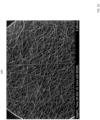
- FIG. 1A Shown in FIG. 1A is a magnified photograph of a representative portion of an exemplary nonwoven fiber carbon veil that is well suited in connection with the claimed invention.
- the fiber sheet comprises a plurality of individual, substantially straight untangled fibers all of which fall within a specified range of length (e.g., 6-12 mm).
- each individual fiber of the nonwoven sheet is desirably in contact with one or more other individual fibers as part of a nonwoven structure of the sheet
- ideal contact differs from entanglement in that entanglement typically involves two or more fibers wound around each other along a longitudinal axis of fibers, whereas preferred contact comprises straight, unentangled fibers having multiple points of contact with other straight unentangled fibers.
- FIG. 1B Shown in Fig. 1B is a top view of an exemplary heating element 100 comprising a carbon veil comprising electrically conductive veil busbar strips 204 and 208, which busbars typically comprise a copper layer coating over the carbon veil, and section 206 located between the busbars.
- electrical connectors are typically connected to each of the veil busbars to apply a voltage across the busbars that produces an electrical current flowing through the veil, which current causes section 206 to evenly generate heat resulting from the electrical resistance of section 206.
- the carbon veil heating element may be manufactured at generally any size (length, width, and at any thickness, but preferably with a thickness of less than 1 mm, and more preferably with a thickness of ⁇ 40 ⁇ m, and having a weight of ⁇ 50 g/m2.
- the extremely low weight and thickness makes the carbon veil non-invasive such that it does not change the properties of a product into which it is embedded.
- the veil is porous, it lends itself to being embedded in products in which the product matrix impregnates the veil, such as in flooring products (e.g. vinyl, PVC, or other polymer flooring sheet products, linoleum, underlayment for tile, hardwood, carpet, etc.).
- the characteristics of the veil are particularly beneficial for use in flooring applications comprising thin sheeting products, such as polyvinyl chloride (PVC) flooring, which is typically only between 3mm and 4 mm thick.
- PVC polyvinyl chloride
- the minimal thickness of the carbon veil permits it to be embedded just below the surface of the flooring (i.e., close to the walking surface). Embedding the carbon veil just below the walking surface of the flooring minimizes heat up time and energy consumption.
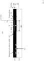
- FIG. 2 A comparison between exemplary installations of a conventional electric wire/liquid tubing heater and an exemplary embedded carbon veil is illustrated relative to a cross section of a floor structure 210 depicted in FIG. 2 .
- electrical wires and/or tubing 212 are shown installed between subfloor 218 and the flooring section 216.
- the wires/tubes are buried a significant distance below the surface of the flooring section 216 and by their very nature constitute relatively hotter linear portions defined by each of the wires/tubes separated by relatively less hot spaces between the wires/tubes.
- carbon veil 214 is embedded just below the floor surface and evenly covers an entire area A1. Generally, the carbon veil produces heat Q over surface area A2, which is transferred to the ambient air by convection.
- Tables 1 and 2 below show a comparison between the characteristics of embedded carbon veil 214 and wires/tubes 212 shown in FIG. 2 , based upon known characteristics of the Applicant's Power Film product, which comprises a coated carbon veil.
- the basic advantages of using an embedded carbon veil are not materially changed versus the Power Film product.
- the temperature of the heating element for the embedded veil only has to reach a temperature of 33°C, whereas the tubes 212 must reach a temperature of 49°C and the electric wires 212 must reach a temperature of 81°C to achieve the same temperature of 21°C at the heated floor surface.
- heating the floor to a desired temperature with an embedded carbon veil just below the floor surface only requires heating the carbon veil to a much lower temperature than the electric cable and/or the water heating tubes, the carbon veil based system consumes much less power.
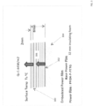
- FIG. 3 further illustrates the impact of distance of the carbon veil relative to the floor surface.
- the carbon veil in position 302 (at the "base") between subfloor 304 and floor covering 306, is roughly 8 mm ("d" in Fig. 2 ) from the top surface of the floor, whereas when embedded directly into the floor at position 300, it is only 2 mm (“0.25d” in FIG 2 ) from the walking surface of floor 306.
- the closer the carbon veil is positioned from the top surface of the floor the more efficient the carbon veil will be in heating up the floor surface.
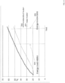
- FIG. 4 shows a plot of time versus surface temperature of the floor for heat flow through a woven glass/epoxy laminate, which approximates the difference in having the embedded carbon veil heater just below the surface of the floor versus the carbon veil positioned in between the flooring and the subflooring.
- the surface temperature of the flooring increases more rapidly when the carbon veil is positioned just below the floor surface.
- the embedded carbon veil utilizes approximately 42% less energy overall in the span of time depicted.
- the overall energy usage of the Embedded Power Film is 0.66 the value of energy usage in the "Base" Power Film.
- Table 2 shows the difference in energy needed for respective heating elements to supply the desired temperature, including the difference between positioning the carbon veil at "Embedded” and “Base” positions as described above.
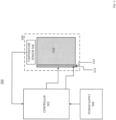
- FIG. 5 An example of a heated flooring system 508 including a controller is shown in FIG. 5 .
- FIG. 5 shows a system with a heated floor section 510 which has a carbon veil embedded directly below its walking surface. Separate from the heated flooring product 510 are electrical (floor) busbars 512 and 514, as well as an optional temperature sensor 506.
- controller 502 controls the power supplied to floor busbars 512 and 514 via power supply 504. Power may optionally be controlled based on a temperature setpoint of optional temperature sensor 506.
- heated flooring section 510 includes the embedded carbon veil
- the heated flooring product 510 is simply laid on the floor and then electrically connected to floor busbars 512 and 514.
- the floor busbars 512 and 514 may be integrated into a "Power Track" product that facilitates quick installation, as described herein later.
- controller 502 receives an input from the user for setting a desired temperature (e.g., the temperature of the floor surface).
- the input device is not shown in FIG. 5 , but can include a dial, button, touchscreen, etc.
- controller 502 applies a predetermined voltage to floor busbars 512 and 514 which are electrically connected to the veil busbars in the carbon veil embedded within flooring 510. The carbon veil then produces heat in response to the electrical current flowing through it.
- controller 502 uses either a timer or a control signal from temperature sensor 506 to monitor the temperature of the floor itself.
- temperature sensor 506 (which is optional) may be in direct contact with the floor or in close proximity to the floor.
- controller 502 determines if the desired temperature of the floor has been reached. If the desired temperature of the floor has been reached, then in step 610, controller 502 stops applying voltage to busbars 512 and 514. If, however, the desired temperature is not reached, controller 502 continues applying the voltage to the busbars.
- the temperature sensor can thus cycle the power to the heater on and off as necessary, in accordance with any algorithm to known in the art for use in maintaining heated flooring or ambient air temperatures, to maintain a desired temperature at the floor surface or of the room, generally.
- Embedding the carbon veil into the flooring product greatly simplifies installation of a heated floor. Exemplary installations of a PVC floor product with an embedded carbon veil are is shown in detail in FIGs. 7 and 8 .
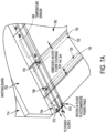
- FIG. 7 illustrates a PVC flooring product installed in a corner of a room adjacent a wall.
- a channel 704 is cut from the subfloor.
- a recessed floor busbar system including busbars 512 and 514, is then installed in this channel, such as using the "Power Track" product as described herein.
- the PVC flooring 700 with the embedded carbon veil may then be laid (e.g. using adhesive backing) over the desired area of the floor to be covered, including over the recessed floor busbar system.
- the PVC flooring 700 not only covers the subfloor but also covers floor busbars 512 and 514.
- conductive fasteners such as bolts and/or screws or the like 706 and 708, are utilized to penetrate the flooring product through the veil busbars and into the floor busbars.
- Each conductive fastener essentially pierces the electrically conductive veil busbars of the carbon veil and therefore establishes an electrical connection from the veil busbars to the floor busbars 512 and 514 (i.e., respective positive and negative busbars are connected to one another).
- FIG. 7 depicts exemplary cross sections of bolts 706 and 708 as well as an example of countersunk screws 710 and 712 that may be used.
- Temperature sensor 506 may also be installed inside the recessed portion of the subfloor (i.e., below the flooring) to be in close proximity to the flooring that it controls. Temperature sensor 506 (regardless of its installation location) provides the ability to sense the actual temperature of the floor, if desired, and report this information back to the controller.
- the connection between the temperature sensor may be wired (related wiring not shown in the figure, for simplicity, but the various connections required will be understood to one of skill in the art) or may be wireless, using Bluetooth ® or any other wireless communication protocol.
- floor busbars 512 and 514 are connected to controller 502 as shown in FIG. 5 .
- the controller 502 then applies voltage across these busbars which then conducts electricity through the carbon veil of the flooring product via the connection between the veil busbars in the carbon veil and the conductive fasteners 706 and 708 located periodically on the floor along the length of the floor to align with the veil busbars.
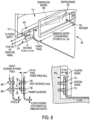
- floor busbars 512 and 514 may be installed on or in the adjacent wall 714, as illustrated in FIG. 8 .
- a channel or recess 800 may be cut into the wall to accommodate the floor busbars, the busbars may simply be installed on top of the wall and then covered by the baseboard.
- the PVC flooring with the embedded carbon veil 700 may be laid on the subfloor.
- PVC flooring 700 may be cut to a greater length than the floor area to be covered, such that the flooring overlaps the wall a by a desired length (e.g. about 4 inches) to permit it to overlap the wall, wherein it is connected to floor busbars 512 and 514.
- the PVC flooring may be screwed directly to floor busbars 512 and 514 utilizing conductive fasteners in locations 706 and 708 or 802 and 804, similar to the installations described and shown previously on the floor, but in this case oriented on the wall rather than on the floor.
- baseboard 702 may then be installed against the base of wall 714.
- the beneficial aspect of this embodiment is that not only are the floor busbars 512 and 514 hidden by the baseboard 702, but the fasteners 706 and 708 or 802 and 804 along the electrically connected edge of the floor are also covered by baseboard 702. This allows a seamless installation that is visually appealing, and also enables troubleshooting of the electrical connections by simply removing the baseboard rather than having to lift up a section of the flooring.
- floor busbars 512 and 514 are connected to controller 502, which applies electrical current to the busbars.
- This electrical current then flows from the floor busbars through fastneners 706 and 708 and through veil busbars to create the electrical potential across the embedded carbon veil in the PVC flooring, which causes the carbon veil to emanate heat.
- the carbon veil may be embedded directly into the flooring sheet itself (e.g., embedded directly into the PVC flooring). This embedding process is performed during manufacturing of the PVC flooring itself.
- Shown in FIG. 9 is an exemplary process for manufacturing a PVC flooring sheet having an embedded carbon veil.
- An upper layer PVC sheet 908 fed from spool 902 and a lower layer PVC sheet 912 fed from spool 906 are fed into a laminator 900, with carbon veil 910 fed from spool 904 sandwiched between sheet 908 and sheet 912.
- Carbon veil 910 may be a "raw" carbon veil comprising only the veil with the conductive veil busbars applied thereto, or the veil may have a coating, such as a PVC or anyother type of coating, on one or both sides, making the veil intermediate similar to Applicant's Power Film product, to facilitate bonding of the upper and lower layers to the veil intermediate.
- Spool 904 includes a carbon veil pre-cut to match the widths of the upper and lower PVC sheet layers dispensed from spools 902 and 906, and has at least one set (typically multiple sets) of veil busbars embedded therein at a desired spacing from one another. All three layers are laminated together to produce a PVC flooring product 914 with an embedded carbon veil.
- a similar technique may be used for the manufacture of flooring from any non-conductive material capable of being laminated or otherwise joined together to sandwich the carbon veil therebetween.
- additional layers may be present above or below the upper and lower layers sandwiching the veil as shown and described herein.
- the flooring products as described herein may refer to underlayments, such as may be installed under carpet, tile, hardwood, etc.
- the veil will typically be more than 1 mm below the uppermost floor surface when embedded in such an underlayment, the advantages of low energy consumption and evenly distributed heat are still present.
- the flooring product as described herein may comprise an acoustic underlayment film.
- films are typically 1.0 to 2.0 mm thick with a 2-3 mm insulating foam backing.
- the carbon veil may be thus embedded between the film and the foam.
- Such a veil may be manufactured by a lamination process as described above, or in an extrusion process, in which the polymer melt from the film extrusion penetrates the porous veil and fuses the acoustic film to the insulating foam.
- a laminating process as described above may be used for creating a heated tarp or cover for a dump truck or other open top truck, to prevent ice or snow build-up during the winter that may otherwise create a hazard for other drivers when built-up ice sloughs off non-heated covers at highway speeds.
- a carbon veil as described herein may be embedded into a 3 mm thick PVC tarpaulin layer during production, similar to the method as described herein for flooring, so that the veil is safely embedded approximately 1 mm below the outer surface of the tarp and activated via the truck battery by a controller.
- the controller may, for example, have inputs connected to a sensor configured to sense a combination of moisture and temperature at which to apply heat to prevent ice build-up.
- Power connections to the tarp may be provided using a power cord with a positive terminal attached to one veil busbar and a negative terminal attached to the other veil busbar, using connectors that affix to and penetrate the tarp and the veil busbars in the appropriate positions.
- the carbon veil in a spool or roll form comprising the carbon veil of a desired width, with the veil busbars spaced at desired widths to provide a desired level of heating potential.
- PVC flooring manufacturers can then simply order a spool of a carbon veil of a desired width and length with veil busbars at a desired spacing to provide a desired heating capability. This spool can then simply be fed into the already existing PVC floor laminating machinery along with the other layers of the PVC flooring to produce an overall heated floor product.
- each busbar may have a rectangular cross section of 20 mm wide x 1.5 mm thick, may comprise preferably pure aluminium grade or copper electrical grade materials of construction, and may have an extruded polymer sheath, such as 1.5mm thick PVC.
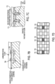
- Figs. 10A and 10B depict a 2-busbar product 1000 in which, for example, the "hot" busbar may be busbar 1030 and the neutral busbar may be busbar 1020, or vice versa, contained together in an insulation matrix 1010.
- Such a product may be manufactured, for example, as depicted in Fig. 11 .
- each busbar at the desired width and thickness and materials of construction may be supplied into the manufacturing process wound on a spool.
- the respective busbars are unwound and fed through a tension controller and a preheating step, and into a die of an extrusion system that extrudes the plastic insulation around the busbars.
- the combined product goes through cooling trough and a capstan drive, through another tension controller, and then cut into desired lengths at a cutting station.
- the manufacturing process may also comprise a "spark testing" step to confirm the busbars are properly spaced and separated from one another in the combined product and do not present a risk of arcing or shorting, which testing step is depicted adjacent the downstream tension controller, but is not limited to any particular location after the extrusion and cooling step.
- spark testing to confirm the busbars are properly spaced and separated from one another in the combined product and do not present a risk of arcing or shorting, which testing step is depicted adjacent the downstream tension controller, but is not limited to any particular location after the extrusion and cooling step.
- the "Power Track" product may be supplied in one or more standard lengths, which lengths can then be joined with connectors, as depicted in Figs. 10C-10E .
- each length of Power Track is preferably provided for installation with a predetermined length of each busbar protruding from the insulation on both ends (which may be accomplished as part of the manufacturing process by sending the cut lengths through a stripping station).
- Connector 1040 comprises insulation 1060 surrounding hollow conductive sheaths 1050 and 1052, each sheath dimensioned to slip over the protruding ends of the busbars.
- the connectors may be manufacturing in a similar manner as the power track, except with continuous spools of sheath material, comprising a rectangular annular cross section as shown in Fig. D, supplied to the extrusion step instead of busbars, and the connectors are cut into much shorter lengths than the Power Track lengths.
- a first length of Power Track 1000a may be joined to a second length 1000b using connector 1040.
- the busbars when joined, may have a gap 1070, such as for example, 2-3 mm, between the busbar 1020a of track 1000a and busbar 1020b of track 1000b.
- the electrical connection between the 1020a and 1020b may rely upon an interference fit between the conductive sheath and the busbar as shown for busbar 1020b in Fig. 10C , or may further comprise a conductive fastener 1080 applied to pierce the sheath and busbar, as shown for busbar 2020a in Fig. 10C .
- the fastener design may resemble any of the other fasteners depicted herein, may or may not protrude completely through the insulation on both sides of the connector, but preferably any protruding features of the fastener are insulated either as provided, or by adding an electrical insulator over top, such as using tape or the like.
- Figs. 10A,B and D are 2-busbar track and connector
- embodiments with 3 busbars would be essentially identical, with one extra busbar.
- single insulated busbars may also be manufactured using a similar process and connected together using similar, single-busbar-sheath connectors.
- the Power Track product as described herein is not limited to any number of busbars. Whether integrated together in the Power Track product, or separately, the insulated busbars may be manufactured in a continuous length and cut to length as required.
- the floor busbars may be preferably provided in a Power Track configuration for ease of installation, the invention is not limited to any particular configuration for the floor busbars.
- Heated flooring with an embedded carbon veil heats up quickly and consumes little energy.
- Carbon veils may be inserted into very thin products that traditional wires/tubes cannot typically accommodate.
- the carbon veil does not add any significant thickness to the overall product and will not negatively impact installation of the product.
- the carbon veil due to its nonwoven structure, always maintains a constant resistance regardless of the size of the veil. This is an additional benefit relative to standard electrical wires, which have a non-uniform resistance, in which the resistance increases with the wire length.
- liquid filled tubes also provide uneven heating over their length, because the liquid temperature drops over the length of the tube as heat dissipates along the run.
Landscapes
- Engineering & Computer Science (AREA)
- Textile Engineering (AREA)
- Floor Finish (AREA)
- Central Heating Systems (AREA)
- Road Paving Structures (AREA)
- Surface Heating Bodies (AREA)
Claims (8)
- Système de chauffage pour le chauffage d'une surface de bâtiment comprenant un sol ou un mur, le système comprenant :une section (510) de revêtement de sol ou de mur comportant un élément chauffant laminaire à voile de carbone (100), une couche supérieure non conductrice (908) présentant une surface exposée orientée vers l'extérieur du sol ou du mur, et une couche inférieure non conductrice (912) présentant une surface exposée face au sol ou au mur, où la couche supérieure non conductrice (908) et la couche inférieure non conductrice (912) sont stratifiées avec l'élément chauffant laminaire à voile de carbone (100) noyé entre la couche supérieure non conductrice (908) et la couche inférieure non conductrice (912), l'élément chauffant à voile de carbone (100) étant disposé à moins de 1 mm de la surface exposée de la couche supérieure non conductrice (908), l'élément chauffant à voile de carbone (100) comprenant au moins deux barres omnibus de voile électro-conductrices (204, 208) espacées l'une de l'autre ;au moins une voie de barre omnibus comprenant au moins deux barres omnibus électriques de voie (512, 514) connectées électriquement aux au moins deux barres omnibus de voile (204, 208), les au moins deux barres omnibus de voie (512, 514) comprenant chacune un métal conducteur ayant une section transversale rectangulaire ayant une largeur et une épaisseur dont la largeur est supérieure à 10 fois l'épaisseur, les au moins deux barres omnibus de voie (512, 514) étant connectées l'une à l'autre et isolées électriquement l'une de l'autre par une matrice d'isolation ;un contrôleur (502) connecté électriquement aux barres omnibus de voie (512, 514) et configuré pour appliquer aux barres omnibus de voie (512, 514) un courant électrique suffisant pour que le voile de carbone (910) produise de la chaleur dans une partie de celui-ci située entre les barres omnibus de voile (204, 208).
- Système de chauffage selon la revendication 1, dans lequel le revêtement de surface comprend un revêtement de sol, et l'au moins une voie de barre omnibus est encastrée dans un sous-plancher sur lequel la section de revêtement de sol est installée.
- Système de chauffage selon la revendication 1, dans lequel l'au moins une voie de barre omnibus est positionnée derrière une plinthe (702) adjacente à la section de revêtement de sol est installé.
- Système de chauffage selon l'une quelconque des revendications 1 à 3, dans lequel l'au moins une voie de barre omnibus s'étend sur une longueur de la section de revêtement de sol et est connectée électriquement à des ensembles respectifs de barres omnibus de voile (204, 208) dans l'élément chauffant à voile de carbone (100) à une pluralité d'endroits.
- Système de chauffage selon l'une quelconque des revendications précédentes, comprenant en outre un capteur de température (506) placé dans un emplacement exploitable pour détecter une chaleur émise par la section du revêtement de sol et en communication avec le contrôleur (502), dans lequel le contrôleur (502) est configuré pour appliquer un courant électrique aux barres omnibus en fonction d'un signal d'entrée provenant du capteur de température (506).
- Système de chauffage selon l'une quelconque des revendications 1 à 5, dans lequel l'élément chauffant laminaire à voile de carbone (100) comprend une feuille non tissée, voie humide comprenant une pluralité de fibres individuelles non embrouillées ayant toutes une longueur comprise dans une plage de 6 à 12 mm.
- Système de chauffage selon l'une quelconque des revendications 1 à 5 dans lequel l'élément chauffant laminaire à voile de carbone (100) a une épaisseur inférieure à 1 mm.
- Système de chauffage selon l'une quelconque des revendications 1 à 5 dans lequel l'élément chauffant laminaire à voile de carbone (100) a un poids inférieur à 50 g/m2.
Applications Claiming Priority (2)
| Application Number | Priority Date | Filing Date | Title |
|---|---|---|---|
| US201662349858P | 2016-06-14 | 2016-06-14 | |
| PCT/IB2017/000870 WO2017216631A2 (fr) | 2016-06-14 | 2017-06-14 | Produits à éléments chauffants à voile de carbone intégré |
Publications (2)
| Publication Number | Publication Date |
|---|---|
| EP3469856A2 EP3469856A2 (fr) | 2019-04-17 |
| EP3469856B1 true EP3469856B1 (fr) | 2023-08-02 |
Family
ID=59799411
Family Applications (1)
| Application Number | Title | Priority Date | Filing Date |
|---|---|---|---|
| EP17762194.3A Active EP3469856B1 (fr) | 2016-06-14 | 2017-06-14 | Produits à éléments chauffants à voile de carbone intégré |
Country Status (4)
| Country | Link |
|---|---|
| EP (1) | EP3469856B1 (fr) |
| CN (1) | CN109479346A (fr) |
| CA (1) | CA3027476A1 (fr) |
| WO (1) | WO2017216631A2 (fr) |
Families Citing this family (9)
| Publication number | Priority date | Publication date | Assignee | Title |
|---|---|---|---|---|
| CA3001643A1 (fr) | 2015-10-19 | 2017-04-27 | Laminaheat Holding Ltd. | Elements de chauffage stratifies ayant une resistance personnalisee ou non uniforme et/ou des formes irregulieres et procedes de fabrication |
| US10993557B2 (en) | 2018-08-03 | 2021-05-04 | American Sterilizer Company | Pressure management warming headrest |
| EP3544372A1 (fr) | 2018-03-22 | 2019-09-25 | LaminaHeat Holding Ltd. | Éléments de chauffage laminaires à résistance personnalisée ou non uniforme et/ou formes irrégulières et leurs procédés de fabrication |
| US20200260532A1 (en) | 2019-02-08 | 2020-08-13 | Laminaheat Holding Ltd. | Perforated laminar heating element |
| USD911038S1 (en) | 2019-10-11 | 2021-02-23 | Laminaheat Holding Ltd. | Heating element sheet having perforations |
| WO2021155160A2 (fr) | 2020-01-31 | 2021-08-05 | American Sterilizer Company | Système de réchauffement pour patient |
| CA3166473A1 (fr) | 2020-01-31 | 2021-08-05 | Richard P. Nardo | Element chauffant ptc et dispositif de rechauffement le comprenant destine a etre utilise dans un systeme de rechauffement de patient |
| DE102021120697A1 (de) * | 2021-08-09 | 2023-02-09 | Giesecke+Devrient Currency Technology Gmbh | Verfahren zur kontaktierung eines elektrisch leitenden papiergefüges, verbundkörper und verwendung |
| DE102023202413A1 (de) * | 2023-03-16 | 2024-09-19 | Benecke-Kaliko Aktiengesellschaft | Beheizbarer Fußbodenbelag |
Family Cites Families (8)
| Publication number | Priority date | Publication date | Assignee | Title |
|---|---|---|---|---|
| US4534886A (en) * | 1981-01-15 | 1985-08-13 | International Paper Company | Non-woven heating element |
| CN2289305Y (zh) * | 1997-01-30 | 1998-08-26 | 刘思源 | 自紧接线卡 |
| GB2414910A (en) * | 2004-06-05 | 2005-12-07 | John Graham Bryant | Integrated heat generating membrane |
| DE202006007731U1 (de) * | 2006-05-12 | 2006-08-17 | Moletherm Holding Ag | Elektrisch betreibbare Flächenheizelement-Anordnung, insbesondere als Fußboden-Flächenheizelement-Anordnung |
| DE202008004481U1 (de) * | 2008-04-02 | 2009-08-06 | VÖWA GmbH | Wand- oder Bodenbelag |
| DE102009025454A1 (de) * | 2009-06-12 | 2010-12-16 | Strähle + Hess GmbH | Einspeisband oder -leiste zur Versorgung eines flächigen Heizelements mit elektrischer Energie |
| CN202361466U (zh) * | 2011-10-27 | 2012-08-01 | 江苏贝尔装饰材料有限公司 | 发热地板及地板取暖系统 |
| DE202014103607U1 (de) * | 2014-08-04 | 2015-01-09 | Frank von der Weiden | Heizsystem zum Verhindern und/oder Beseitigen von Schimmelbildung an Innenwandflächen von Gebäuden |
-
2017
- 2017-06-14 CN CN201780043749.6A patent/CN109479346A/zh active Pending
- 2017-06-14 EP EP17762194.3A patent/EP3469856B1/fr active Active
- 2017-06-14 WO PCT/IB2017/000870 patent/WO2017216631A2/fr not_active Ceased
- 2017-06-14 CA CA3027476A patent/CA3027476A1/fr not_active Abandoned
Also Published As
| Publication number | Publication date |
|---|---|
| WO2017216631A3 (fr) | 2018-03-01 |
| WO2017216631A2 (fr) | 2017-12-21 |
| CA3027476A1 (fr) | 2017-12-21 |
| EP3469856A2 (fr) | 2019-04-17 |
| CN109479346A (zh) | 2019-03-15 |
Similar Documents
| Publication | Publication Date | Title |
|---|---|---|
| EP3469856B1 (fr) | Produits à éléments chauffants à voile de carbone intégré | |
| EP3245844B1 (fr) | Élément chauffant en tissu | |
| CN100391310C (zh) | 自动调节的加热装置 | |
| EP2931515B1 (fr) | Élément chauffant auto-régulateur, semi-conducteur, flexible | |
| EP2113456B1 (fr) | Panneau de plancher chauffé d'avion | |
| FR3048151A1 (fr) | Structure multicouche pour la realisation d'un revetement de sol ou de mur chauffant | |
| US10775050B2 (en) | Sectionable floor heating system | |
| EP2496889B1 (fr) | Panneau de chauffage et procede associe | |
| US20190137115A1 (en) | Embedded carbon veil heating systems and installation methods | |
| EP2781843A1 (fr) | Fabrication d'un plancher modulaire avec un système de chauffage électrique | |
| WO2019086549A1 (fr) | Ensembles de barres-bus à profil mince et systèmes de chauffage reliés électriquement à ceux-ci | |
| CA2607865A1 (fr) | Element chauffant sous le plancher | |
| DE202009009228U1 (de) | Elektrisch betreibbares Flächenheizelement | |
| JP2008545902A (ja) | 電気式パネル暖房装置および暖房モジュールを備えた建物室内の壁構造 | |
| CA2600775C (fr) | Ruban cristallin chauffant relie a la terre | |
| RU168165U1 (ru) | Пленочный электронагреватель | |
| KR100777050B1 (ko) | 전기 히팅 매트 | |
| DE202014106117U1 (de) | Heizsystem zum Beseitigen und/oder Verhindern von Schimmelbildung an Innenwandflächen von Gebäuden | |
| DE102019131881B4 (de) | Schnell aufheizbares elektrisches Flächenheiz System und Betriebsverfahren | |
| DE102019131875B4 (de) | Elektrische Flächenheizung, Verfahren zum Herstellen einer elektrischen Flächenheizung, selbstbegrenzendes Heizkabel, und Verfahren zum Herstellen eines selbstbegrenzenden Heizkabels | |
| AU2023332229A1 (en) | Space heating film | |
| EP4431821A1 (fr) | Revêtement de sol chauffable | |
| JP4154493B2 (ja) | 発熱シート | |
| JP2003243134A (ja) | 面発熱シート、その製造方法及び発熱シートを用いた床パネル、暖房床、暖房畳並びに暖房システム及び組立床暖房システム | |
| JP2001116274A (ja) | 床暖房装置 |
Legal Events
| Date | Code | Title | Description |
|---|---|---|---|
| STAA | Information on the status of an ep patent application or granted ep patent |
Free format text: STATUS: UNKNOWN |
|
| STAA | Information on the status of an ep patent application or granted ep patent |
Free format text: STATUS: THE INTERNATIONAL PUBLICATION HAS BEEN MADE |
|
| PUAI | Public reference made under article 153(3) epc to a published international application that has entered the european phase |
Free format text: ORIGINAL CODE: 0009012 |
|
| STAA | Information on the status of an ep patent application or granted ep patent |
Free format text: STATUS: REQUEST FOR EXAMINATION WAS MADE |
|
| 17P | Request for examination filed |
Effective date: 20181221 |
|
| AK | Designated contracting states |
Kind code of ref document: A2 Designated state(s): AL AT BE BG CH CY CZ DE DK EE ES FI FR GB GR HR HU IE IS IT LI LT LU LV MC MK MT NL NO PL PT RO RS SE SI SK SM TR |
|
| AX | Request for extension of the european patent |
Extension state: BA ME |
|
| DAV | Request for validation of the european patent (deleted) | ||
| DAX | Request for extension of the european patent (deleted) | ||
| STAA | Information on the status of an ep patent application or granted ep patent |
Free format text: STATUS: EXAMINATION IS IN PROGRESS |
|
| 17Q | First examination report despatched |
Effective date: 20201016 |
|
| GRAP | Despatch of communication of intention to grant a patent |
Free format text: ORIGINAL CODE: EPIDOSNIGR1 |
|
| STAA | Information on the status of an ep patent application or granted ep patent |
Free format text: STATUS: GRANT OF PATENT IS INTENDED |
|
| INTG | Intention to grant announced |
Effective date: 20230118 |
|
| GRAS | Grant fee paid |
Free format text: ORIGINAL CODE: EPIDOSNIGR3 |
|
| GRAA | (expected) grant |
Free format text: ORIGINAL CODE: 0009210 |
|
| STAA | Information on the status of an ep patent application or granted ep patent |
Free format text: STATUS: THE PATENT HAS BEEN GRANTED |
|
| AK | Designated contracting states |
Kind code of ref document: B1 Designated state(s): AL AT BE BG CH CY CZ DE DK EE ES FI FR GB GR HR HU IE IS IT LI LT LU LV MC MK MT NL NO PL PT RO RS SE SI SK SM TR |
|
| REG | Reference to a national code |
Ref country code: GB Ref legal event code: FG4D |
|
| REG | Reference to a national code |
Ref country code: CH Ref legal event code: EP |
|
| REG | Reference to a national code |
Ref country code: DE Ref legal event code: R096 Ref document number: 602017072148 Country of ref document: DE |
|
| REG | Reference to a national code |
Ref country code: IE Ref legal event code: FG4D |
|
| REG | Reference to a national code |
Ref country code: LT Ref legal event code: MG9D |
|
| REG | Reference to a national code |
Ref country code: NL Ref legal event code: MP Effective date: 20230802 |
|
| REG | Reference to a national code |
Ref country code: AT Ref legal event code: MK05 Ref document number: 1596306 Country of ref document: AT Kind code of ref document: T Effective date: 20230802 |
|
| PG25 | Lapsed in a contracting state [announced via postgrant information from national office to epo] |
Ref country code: GR Free format text: LAPSE BECAUSE OF FAILURE TO SUBMIT A TRANSLATION OF THE DESCRIPTION OR TO PAY THE FEE WITHIN THE PRESCRIBED TIME-LIMIT Effective date: 20231103 |
|
| PG25 | Lapsed in a contracting state [announced via postgrant information from national office to epo] |
Ref country code: IS Free format text: LAPSE BECAUSE OF FAILURE TO SUBMIT A TRANSLATION OF THE DESCRIPTION OR TO PAY THE FEE WITHIN THE PRESCRIBED TIME-LIMIT Effective date: 20231202 |
|
| PG25 | Lapsed in a contracting state [announced via postgrant information from national office to epo] |
Ref country code: SE Free format text: LAPSE BECAUSE OF FAILURE TO SUBMIT A TRANSLATION OF THE DESCRIPTION OR TO PAY THE FEE WITHIN THE PRESCRIBED TIME-LIMIT Effective date: 20230802 Ref country code: RS Free format text: LAPSE BECAUSE OF FAILURE TO SUBMIT A TRANSLATION OF THE DESCRIPTION OR TO PAY THE FEE WITHIN THE PRESCRIBED TIME-LIMIT Effective date: 20230802 Ref country code: PT Free format text: LAPSE BECAUSE OF FAILURE TO SUBMIT A TRANSLATION OF THE DESCRIPTION OR TO PAY THE FEE WITHIN THE PRESCRIBED TIME-LIMIT Effective date: 20231204 Ref country code: NO Free format text: LAPSE BECAUSE OF FAILURE TO SUBMIT A TRANSLATION OF THE DESCRIPTION OR TO PAY THE FEE WITHIN THE PRESCRIBED TIME-LIMIT Effective date: 20231102 Ref country code: NL Free format text: LAPSE BECAUSE OF FAILURE TO SUBMIT A TRANSLATION OF THE DESCRIPTION OR TO PAY THE FEE WITHIN THE PRESCRIBED TIME-LIMIT Effective date: 20230802 Ref country code: LV Free format text: LAPSE BECAUSE OF FAILURE TO SUBMIT A TRANSLATION OF THE DESCRIPTION OR TO PAY THE FEE WITHIN THE PRESCRIBED TIME-LIMIT Effective date: 20230802 Ref country code: LT Free format text: LAPSE BECAUSE OF FAILURE TO SUBMIT A TRANSLATION OF THE DESCRIPTION OR TO PAY THE FEE WITHIN THE PRESCRIBED TIME-LIMIT Effective date: 20230802 Ref country code: IS Free format text: LAPSE BECAUSE OF FAILURE TO SUBMIT A TRANSLATION OF THE DESCRIPTION OR TO PAY THE FEE WITHIN THE PRESCRIBED TIME-LIMIT Effective date: 20231202 Ref country code: HR Free format text: LAPSE BECAUSE OF FAILURE TO SUBMIT A TRANSLATION OF THE DESCRIPTION OR TO PAY THE FEE WITHIN THE PRESCRIBED TIME-LIMIT Effective date: 20230802 Ref country code: GR Free format text: LAPSE BECAUSE OF FAILURE TO SUBMIT A TRANSLATION OF THE DESCRIPTION OR TO PAY THE FEE WITHIN THE PRESCRIBED TIME-LIMIT Effective date: 20231103 Ref country code: FI Free format text: LAPSE BECAUSE OF FAILURE TO SUBMIT A TRANSLATION OF THE DESCRIPTION OR TO PAY THE FEE WITHIN THE PRESCRIBED TIME-LIMIT Effective date: 20230802 Ref country code: AT Free format text: LAPSE BECAUSE OF FAILURE TO SUBMIT A TRANSLATION OF THE DESCRIPTION OR TO PAY THE FEE WITHIN THE PRESCRIBED TIME-LIMIT Effective date: 20230802 |
|
| PG25 | Lapsed in a contracting state [announced via postgrant information from national office to epo] |
Ref country code: PL Free format text: LAPSE BECAUSE OF FAILURE TO SUBMIT A TRANSLATION OF THE DESCRIPTION OR TO PAY THE FEE WITHIN THE PRESCRIBED TIME-LIMIT Effective date: 20230802 |
|
| PG25 | Lapsed in a contracting state [announced via postgrant information from national office to epo] |
Ref country code: ES Free format text: LAPSE BECAUSE OF FAILURE TO SUBMIT A TRANSLATION OF THE DESCRIPTION OR TO PAY THE FEE WITHIN THE PRESCRIBED TIME-LIMIT Effective date: 20230802 |
|
| PG25 | Lapsed in a contracting state [announced via postgrant information from national office to epo] |
Ref country code: SM Free format text: LAPSE BECAUSE OF FAILURE TO SUBMIT A TRANSLATION OF THE DESCRIPTION OR TO PAY THE FEE WITHIN THE PRESCRIBED TIME-LIMIT Effective date: 20230802 Ref country code: RO Free format text: LAPSE BECAUSE OF FAILURE TO SUBMIT A TRANSLATION OF THE DESCRIPTION OR TO PAY THE FEE WITHIN THE PRESCRIBED TIME-LIMIT Effective date: 20230802 Ref country code: ES Free format text: LAPSE BECAUSE OF FAILURE TO SUBMIT A TRANSLATION OF THE DESCRIPTION OR TO PAY THE FEE WITHIN THE PRESCRIBED TIME-LIMIT Effective date: 20230802 Ref country code: EE Free format text: LAPSE BECAUSE OF FAILURE TO SUBMIT A TRANSLATION OF THE DESCRIPTION OR TO PAY THE FEE WITHIN THE PRESCRIBED TIME-LIMIT Effective date: 20230802 Ref country code: DK Free format text: LAPSE BECAUSE OF FAILURE TO SUBMIT A TRANSLATION OF THE DESCRIPTION OR TO PAY THE FEE WITHIN THE PRESCRIBED TIME-LIMIT Effective date: 20230802 Ref country code: CZ Free format text: LAPSE BECAUSE OF FAILURE TO SUBMIT A TRANSLATION OF THE DESCRIPTION OR TO PAY THE FEE WITHIN THE PRESCRIBED TIME-LIMIT Effective date: 20230802 Ref country code: SK Free format text: LAPSE BECAUSE OF FAILURE TO SUBMIT A TRANSLATION OF THE DESCRIPTION OR TO PAY THE FEE WITHIN THE PRESCRIBED TIME-LIMIT Effective date: 20230802 |
|
| REG | Reference to a national code |
Ref country code: DE Ref legal event code: R097 Ref document number: 602017072148 Country of ref document: DE |
|
| PG25 | Lapsed in a contracting state [announced via postgrant information from national office to epo] |
Ref country code: IT Free format text: LAPSE BECAUSE OF FAILURE TO SUBMIT A TRANSLATION OF THE DESCRIPTION OR TO PAY THE FEE WITHIN THE PRESCRIBED TIME-LIMIT Effective date: 20230802 |
|
| PLBE | No opposition filed within time limit |
Free format text: ORIGINAL CODE: 0009261 |
|
| STAA | Information on the status of an ep patent application or granted ep patent |
Free format text: STATUS: NO OPPOSITION FILED WITHIN TIME LIMIT |
|
| 26N | No opposition filed |
Effective date: 20240503 |
|
| PG25 | Lapsed in a contracting state [announced via postgrant information from national office to epo] |
Ref country code: SI Free format text: LAPSE BECAUSE OF FAILURE TO SUBMIT A TRANSLATION OF THE DESCRIPTION OR TO PAY THE FEE WITHIN THE PRESCRIBED TIME-LIMIT Effective date: 20230802 |
|
| PG25 | Lapsed in a contracting state [announced via postgrant information from national office to epo] |
Ref country code: BG Free format text: LAPSE BECAUSE OF FAILURE TO SUBMIT A TRANSLATION OF THE DESCRIPTION OR TO PAY THE FEE WITHIN THE PRESCRIBED TIME-LIMIT Effective date: 20230802 |
|
| PG25 | Lapsed in a contracting state [announced via postgrant information from national office to epo] |
Ref country code: BG Free format text: LAPSE BECAUSE OF FAILURE TO SUBMIT A TRANSLATION OF THE DESCRIPTION OR TO PAY THE FEE WITHIN THE PRESCRIBED TIME-LIMIT Effective date: 20230802 |
|
| PG25 | Lapsed in a contracting state [announced via postgrant information from national office to epo] |
Ref country code: MC Free format text: LAPSE BECAUSE OF FAILURE TO SUBMIT A TRANSLATION OF THE DESCRIPTION OR TO PAY THE FEE WITHIN THE PRESCRIBED TIME-LIMIT Effective date: 20230802 |
|
| PG25 | Lapsed in a contracting state [announced via postgrant information from national office to epo] |
Ref country code: LU Free format text: LAPSE BECAUSE OF NON-PAYMENT OF DUE FEES Effective date: 20240614 |
|
| PG25 | Lapsed in a contracting state [announced via postgrant information from national office to epo] |
Ref country code: BE Free format text: LAPSE BECAUSE OF NON-PAYMENT OF DUE FEES Effective date: 20240630 |
|
| REG | Reference to a national code |
Ref country code: BE Ref legal event code: MM Effective date: 20240630 |
|
| PGFP | Annual fee paid to national office [announced via postgrant information from national office to epo] |
Ref country code: DE Payment date: 20250530 Year of fee payment: 9 |
|
| PGFP | Annual fee paid to national office [announced via postgrant information from national office to epo] |
Ref country code: GB Payment date: 20250530 Year of fee payment: 9 |
|
| PGFP | Annual fee paid to national office [announced via postgrant information from national office to epo] |
Ref country code: FR Payment date: 20250530 Year of fee payment: 9 |
|
| PGFP | Annual fee paid to national office [announced via postgrant information from national office to epo] |
Ref country code: IE Payment date: 20250530 Year of fee payment: 9 |
|
| PGFP | Annual fee paid to national office [announced via postgrant information from national office to epo] |
Ref country code: CH Payment date: 20250701 Year of fee payment: 9 |
|
| PG25 | Lapsed in a contracting state [announced via postgrant information from national office to epo] |
Ref country code: CY Free format text: LAPSE BECAUSE OF FAILURE TO SUBMIT A TRANSLATION OF THE DESCRIPTION OR TO PAY THE FEE WITHIN THE PRESCRIBED TIME-LIMIT; INVALID AB INITIO Effective date: 20170614 |
|
| PG25 | Lapsed in a contracting state [announced via postgrant information from national office to epo] |
Ref country code: HU Free format text: LAPSE BECAUSE OF FAILURE TO SUBMIT A TRANSLATION OF THE DESCRIPTION OR TO PAY THE FEE WITHIN THE PRESCRIBED TIME-LIMIT; INVALID AB INITIO Effective date: 20170614 |