EP3469911A1 - Dispositif de transport de saucisse oblongue comportant une courbure - Google Patents
Dispositif de transport de saucisse oblongue comportant une courbure Download PDFInfo
- Publication number
- EP3469911A1 EP3469911A1 EP18185369.8A EP18185369A EP3469911A1 EP 3469911 A1 EP3469911 A1 EP 3469911A1 EP 18185369 A EP18185369 A EP 18185369A EP 3469911 A1 EP3469911 A1 EP 3469911A1
- Authority
- EP
- European Patent Office
- Prior art keywords
- conveyor
- belts
- sausage
- sausages
- conveyor belts
- Prior art date
- Legal status (The legal status is an assumption and is not a legal conclusion. Google has not performed a legal analysis and makes no representation as to the accuracy of the status listed.)
- Granted
Links
Images



Classifications
-
- A—HUMAN NECESSITIES
- A22—BUTCHERING; MEAT TREATMENT; PROCESSING POULTRY OR FISH
- A22C—PROCESSING MEAT, POULTRY, OR FISH
- A22C11/00—Sausage making ; Apparatus for handling or conveying sausage products during manufacture
- A22C11/008—Conveying sausages in horizontal position
-
- B—PERFORMING OPERATIONS; TRANSPORTING
- B65—CONVEYING; PACKING; STORING; HANDLING THIN OR FILAMENTARY MATERIAL
- B65B—MACHINES, APPARATUS OR DEVICES FOR, OR METHODS OF, PACKAGING ARTICLES OR MATERIALS; UNPACKING
- B65B35/00—Supplying, feeding, arranging or orientating articles to be packaged
- B65B35/56—Orientating, i.e. changing the attitude of, articles, e.g. of non-uniform cross-section
- B65B35/58—Turning articles by positively-acting means, e.g. to present labelled portions in uppermost position
-
- B—PERFORMING OPERATIONS; TRANSPORTING
- B65—CONVEYING; PACKING; STORING; HANDLING THIN OR FILAMENTARY MATERIAL
- B65G—TRANSPORT OR STORAGE DEVICES, e.g. CONVEYORS FOR LOADING OR TIPPING, SHOP CONVEYOR SYSTEMS OR PNEUMATIC TUBE CONVEYORS
- B65G47/00—Article or material-handling devices associated with conveyors; Methods employing such devices
- B65G47/22—Devices influencing the relative position or the attitude of articles during transit by conveyors
- B65G47/24—Devices influencing the relative position or the attitude of articles during transit by conveyors orientating the articles
- B65G47/248—Devices influencing the relative position or the attitude of articles during transit by conveyors orientating the articles by turning over or inverting them
- B65G47/252—Devices influencing the relative position or the attitude of articles during transit by conveyors orientating the articles by turning over or inverting them about an axis substantially perpendicular to the conveying direction
-
- B—PERFORMING OPERATIONS; TRANSPORTING
- B65—CONVEYING; PACKING; STORING; HANDLING THIN OR FILAMENTARY MATERIAL
- B65B—MACHINES, APPARATUS OR DEVICES FOR, OR METHODS OF, PACKAGING ARTICLES OR MATERIALS; UNPACKING
- B65B25/00—Packaging other articles presenting special problems
- B65B25/06—Packaging slices or specially-shaped pieces of meat, cheese, or other plastic or tacky products
- B65B25/065—Packaging slices or specially-shaped pieces of meat, cheese, or other plastic or tacky products of meat
Definitions
- the invention relates to a device for transporting elongated sausages having a curvature.
- Sausages are known to be made in different calibers and depending on Wurstart either a straight, elongated shape, or are, as most, curved, so have a bend.
- the finished sausages are, optionally after a corresponding treatment, transported one behind the other lying on a conveyor.
- the sausages are arranged with their longitudinal direction transversely to the conveying direction on the conveyor. They are usually transported to a corresponding grouping device, in which then from the individual sausages corresponding sausage groups are formed, after which the individual sausage groups are gripped via a corresponding handling system and placed in appropriate packaging.
- the invention is therefore based on the problem of providing a contrast improved device for transporting elongated sausages having a curvature.
- a device for transporting elongated sausages having a curvature comprising a first conveyor comprising two laterally spaced, circulating conveyor belts or belts with respective lugs for random picking up the sausages, in each case one end section in two adjacent lugs a sausage is receivable, wherein at least in sections along the conveyor line below the conveyor belts or belts, a space for enabling a pendulum of stored in the edge region on the conveyor belts or belts sausages so that they hang with the curvature down into the free space is provided with a start-up component, against which a sagging sausage runs, above which they move in the direction of the conveying plane is swung up, and with a second conveyor for taking over the swung sausage.
- the transport device two conveyors are used, between which an automatic alignment is provided, which uses the fact that the sausages are crooked, as working or functional means for aligning the sausages.
- the first conveyor has two laterally spaced apart conveyor belts or conveyor belts, which have corresponding lugs, in each of which a sausage is received. This means that each sausage rests on the two conveyor belts or conveyor belts in the region of their ends.
- the sausages are substantially horizontal and are supported via a arranged between the conveyor belts or belt support means, if it is assumed that the first conveyor is also positioned horizontally.
- the sausages then enter the area of a free space in which they rest only in the region of their sausage ends on the two spaced conveyor belts or conveyor belt.
- These support points form pivot points, respectively defining a pivot axis, around which the sausage now, as over its entire length just not supported, can swing through, so pivots down with its curvature or her stomach into the space. This means that through this swinging the sausage is only in the area of their lateral ends on the conveyor belts or belts, their central area with the curvature hangs down into the space. This is done with each sausage, regardless of whether in the promotion now the curvature or the belly was aligned in the conveying direction or against the conveying direction.
- the sausages are then transferred to a second conveyor on which then all the sausages are aligned exactly the same with respect to the orientation of their curvature.
- This can then be either a grouping or a handling device, eg. B. connect a delta grapple for direct shipment in appropriate packaging or the like.
- the alignment or correction according to the invention is based solely on the very fact that on the sausage side a certain shape is predetermined, which leads to corresponding problems in the prior art, that is, the invention ultimately just the disadvantageous in the prior art circumstance Use it and use it as a feature.
- the sausages are transported horizontally, for example, on the first conveyor. With their edges, they are included in the cleats of the two conveyor belts or conveyor belts as stated. In the area of the sausage center, ie in the abdominal area, they are also supported by a supporting device and can be accommodated, for example, on a corresponding sliding surface, which enables a good sliding of the sausages entrained via the lateral cleats. It is expedient, however, if, as an alternative to such a sliding surface upstream of the free space between the conveyor belts or belts another circulating conveyor is provided, which also has lugs, which are arranged in extension of the lugs of the conveyor belts or belts and record the sausage.
- the first conveyor ultimately comprises two separate conveyors, namely the two lateral conveyor belts or belts and, in between, another conveyor in the form of a corresponding conveyor belt or the like, all the lugs being axially aligned with one another.
- this middle conveyor or this middle conveyor so the sausages are during normal transport.
- the funding, z. B. the tunneling belt ends when the transition to the free space is reached, because there, of course, the sausages are no longer centrally support, after they should commute there.
- a central element for aligning the sausages is the Anletterteil against which the sausages run, and over which they are swung back defined.
- this starting component may be designed as a bevel arranged in the free space, preferably in the form of a ramp-like, obliquely arranged plate, alternatively also as a obliquely arranged strut or bar.
- the drooping sausages run with their lowest point, ie the belly tip, against this slope and are inevitably slowed down, while the two ends, lying in the tunnels, are moved on.
- the bevel be it in the form of the plate or the strut or strip, for example, as a metal component, preferably made of stainless steel. But it may also be a plastic component, for example made of PTFE or another material.
- the slope over a strand of a space arranged in the circulating conveyor belt, which rotates at a lower speed than the conveyor belts or belts, or by means of a roller cascade, the plurality of rotatable rollers arranged in succession in the transporting direction, which, if actively driven, rotate at a lower speed than the conveyor belts or belts.
- the operating principle here is the same as described in the alternative described above.
- the slope is not fixed, but formed by means of a conveyor belt having a sloping portion or an inclined strand against which the individual sausages run.
- the speed of movement of the inclined strand is slower than that of the lateral conveyor belts or belts, it also comes here to slow down and pull up along the slope to the horizontal alignment position.
- the advantage of using a circulating conveyor belt to form the slope is that the conveyor belt can be continuously cleaned, that is, below which a corresponding cleaning station can be provided, through which the conveyor belt runs permanently, so that it is always cleaned.
- the sausages are actively pulled up along the slope, hence an increased stress, which, since it is organic material, can lead to a coating, is given.
- an inclined roller cascade to form the slope may be provided, wherein the rollers are mounted in a suitable frame.
- rollers are driven and rotate at a speed which is lower than the transport speed of the conveyor belts or belts, so that here also a braking effect is used, which leads in connection with the tilting to swing up.
- the rollers may for example be coupled via a common belt, so that only one role is actively driven by a motor. Alternatively, the rollers can not be driven, but only be set on startup of a sausage in rotation.
- the angle of attack of the slope can be adjusted manually or automatically, for example, by the slope, z.
- the plate can be brought into the defined oblique positions, which are defined for example via corresponding locking or Einhnaturepositionen on a frame or the like.
- a control cylinder or the like can be used to change the angle continuously or automatically. This can be used to set the distance and the duration, respectively during which the sausages are in contact with the slope, and thus also the speed of the high pivoting operation, as well as an adaptation to correspondingly varying sausage lengths with varying radii of curvature or sausage caliber and the like is possible ,
- the starting component in the form of a positionally fixed bevel or a moving bevel
- a pin which can be moved up and down, preferably vertically, whereby sagging sausage runs against the raised pin which, after pivoting the sausage downwards is moved.
- the pin thus forms a kind of stop against which the sausage runs and is swung up due to the braking effect.
- the pen itself goes up and down with the appropriate clock, so it is moved in and out of the conveyor. Of course, it is located in the conveyor line only when a sausage comes and is to be swung up, to then let the sausage out again and release it for continued transport, it is lowered again.
- the movement of the pin can be controlled via a corresponding actuator or the like with the appropriate frequency.
- the starting component can also be formed in the form of a rotatable roller.
- the roller may be driven and rotate at a speed slower than the conveyor belt or conveyor speed.
- Each sausage runs against the roll or drum and is braked there on the one hand, on the other hand, it is, as a result of the round cross-section of the roll or drum on which the transported sausage runs, also swung.
- the roller can not be driven, but only be set on startup of a sausage in rotation.
- the sausages are received in corresponding lugs on the conveyor belts or conveyor belt and optionally the conveyor located between them.
- the studs on the conveyor belts or belts and possibly the conveying means disposed therebetween are spaced apart in the conveying direction such that two adjacent sausages received in the tunnels do not touch one another. That is, the distance seen in the conveying direction lug spacing is dimensioned sufficiently large, so that even with stronger curvature, the sausages do not rest against each other.
- An expedient development of the invention provides that in the region of the free space deflection devices for tilting the conveyor belts or belts are provided about their longitudinal axis inwardly toward the free space.
- a deflection device is expedient when using flat conveyor belts or belts. If circular conveyor belts or belts are used in cross section, such a deflection device can be dispensed with.
- the flat conveyor belts or conveyor belts are thus pivoted slightly on both sides of these deflectors inward, so that according to the support points on which the sausages rest on the two conveyor belts or conveyor belt, pivot inwards.
- This is expedient for the fürpendelvorgang, as this way a kind of forced operation of the conveyor belts or belts is ensured, ie a change in position, which can be actively transmitted to the respective sausage ends, which is the fürpendelfest conducive.
- the deflection in the form of two rails that guide the conveyor belts or belts in the conveying direction and a Be formed tilting guiding surface form be formed.
- the conveyor belts or conveyor belt thus run in the region of the free space on the two deflection devices respectively their guide surfaces, and are, as a result of the tilted inward guide surface shape, inevitably tilted inward.
- the tilt angle should be between 15-60 °, in particular between 25-45 ° and preferably about 30 °. After tilting, when the conveyor belts or conveyor belts run off the deflection devices, they inevitably align themselves again in parallel.
- vibration means for generating vibrations to the deflection at least in the field of leadership of the conveyor belts or belts.
- this vibration means it is possible to put the deflection in higher-frequency vibrations, which means that also run on the deflection conveyor belts or conveyor belts vibrate accordingly.
- the sausages resting against them or in the tunnels also experience the vibrations in this area.
- These vibrations now cause the sausages inevitably, if given, can solve their investment in the gallery walls, so therefore it does not fit firmly. This is particularly advantageous for swiveling up, as the sausages can not get caught on the lug walls.
- An expedient development of the invention provides that the conveyor belts or belts manually or automatically adjustable in their distance from each other. That is, if necessary, the conveyor belts may be positioned either closer or further apart. This makes it possible to adapt the device in relation to correspondingly different lengths sausages.
- This lateral adjustment of the two conveyor belts or conveyor belt can be done manually, for example via corresponding threaded spindle drives, which can be screwed together or apart and with which the corresponding guides of the conveyor belts or belts are coupled.
- An automatic adjustment via corresponding actuating cylinder is conceivable, in which case the sausage length can be automatically detected by means of a detection device, whereupon the orientation of the conveyor belts or belts can take place, and consequently the width can be correspondingly changed automatically.
- the conveyor belts or belts and, if appropriate, the conveying means arranged therebetween are detachably and exchangeably arranged on the moving means moving them.
- the conveyor belts or belts run over corresponding drive or deflection rollers. It is now possible to remove them and replace them with other conveyor belts or belts or conveying means which have a smaller or larger lug width.
- a first band or belt pair for a first caliber interval, z For caliber 10 - 18 mm (the caliber indicates the diameter of the sausage in mm) interpreted.
- a second replaceable pair of belts or straps is designed with lugs for a caliber interval of 18-25 mm and a third pair of belts or belts for a third caliber interval of 25-40 mm, or the like. This allows a simple and flexible adaptation of the device with respect to the sausage caliber of the sausages to be conveyed, so that the device can also be used for different calibers, especially in connection with the adjustment of the distance of the conveyor belts or belts. If the central conveyor also has studs, this can also be exchanged.
- the first conveyor may be associated with an alignment device for laterally aligning the sausages received in the cleats.
- This alignment device ensures that all the sausages are aligned with one end relative to a common plane or line. Since most of the mechanically produced sausages already have almost equal lengths, it can be ensured hereby that the one behind the other arranged sausages are all positioned the same and also rest with respect to the pendulum and Hochschwenkvorgangs in the same areas end on the conveyor belts or conveyor belt.
- Such an alignment device can be, for example, a positionally fixed rotating wheel which is either round and runs with its circumferential surface against the sausage ends, or which has at the individual sausages end-engaging alignment sections, so gear-like projections. In this case, a corresponding synchronization with respect to the studs is required.
- the again raised, but then aligned sausages are transferred to a second conveyor, where either a grouping or immediately a corresponding handling of the aligned sausages takes place.
- This second conveyor preferably comprises a plurality of conveyor belts or belts arranged in parallel, wherein the conveyor belts or belts of the first conveyor run between two conveyor belts or belts of the second conveyor. This means that the conveyors virtually intermesh, so that a very simple transfer is possible because in the same transport level, a seamless transition can be realized.
- the second conveying device is assigned a grouping device for forming a sausage group, that is to say therefore a defined group of a defined number of sausages is formed in the region of the second conveying device.
- a sausage group may comprise, for example, 5 or 10 sausages, depending on how the corresponding package is to be designed and how the downstream handling system is set up.
- Such a grouping setting can comprise, for example, at least one brake or stop element that can be reversibly inserted into the path of movement of the sausages for braking or stopping a sausage to form a sausage group.
- a brake or stop element such as a z. B.
- vertically movable pin that can be moved over a control cylinder or the like, serves as a sort of starting element against which the first sausage runs. Against this first sausage then runs the next sausage and against this in turn the next, etc., until the corresponding sausage group is formed, whereafter the braking or stopping element is again brought out of the path of movement in order to transport the formed sausage group further to the handling station.
- two laterally spaced pins are provided, so that virtually a stop line or - level is formed and slipping around a vertical axis is excluded.
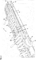
- Fig. 1 shows a device 1 according to the invention for transporting elongated, having a curvature sausages 2.
- the device 1 comprises a first conveyor 3 comprising two laterally spaced apart circulating conveyor belts or conveyor belt 4, the respective outside projecting driver 5, wherein between each driver 5 each a lug 6 is formed.
- each sausage 2 is added and stored with their end portions on the respective conveyor belt or belt 4.
- a sausage 2 is received in each case with its end portions in the region of the studs 6 and with its central region in a stud 9.
- the sausages 2 are virtually random in the horizontal position on the first conveyor 3, that is, there is no defined orientation of the curved sausages with regard to the position of the curvature.
- Fig. 1 clearly shows, the bends or bellies of two adjacent sausages either away from each other or are adjacent to each other, the orientation is completely random.
- the transport device according to the invention it is possible with the transport device according to the invention to bring all the sausages into a common, defined orientation.
- the conveyor belts 4 and the conveyor 7, so also this conveyor belt have on their inner side in each case a toothing 10, 11, with which they in an external toothing 12 (see Fig. 2 ) engage a driven roller.
- a guide roller 13 is provided on which, however, only the conveyor 7, so the central conveyor belt is deflected while the two laterally spaced apart conveyor belts 4 continue to run, they are only guided over the guide roller 13.
- corresponding adjustment means 14 are provided on the drive roller 12 or the deflection roller 13, for example, via which the respective roller is longitudinally displaced and consequently the tension can be varied.
- deflection 17 which are in the form of elongated guide rails and have a corresponding guide groove 18, in each Guide tape or belt 4 enters.
- the deflecting means 17 are designed and positioned so that each conveyor belt 4 or each conveyor belt experiences a slight torsion about its longitudinal axis, in particular Fig. 4 clearly shows.
- each sausage arriving on the deflecting devices 17 is additionally actively vibrated in the region of its support, thus always achieving a slight detachment from the respective longitudinal side support. This can be ensured that each sausage commutes through, even if they previously applied, for example, on the respective adjacent driver 5 and may not yet completely pendulum.
- a vibrating means is merely optional and not mandatory.
- Each sougependelte sausage 2 is still included in the respective lugs 6 of the two adjacent conveyor belts or belts 4. About this they are taken along and transported along the open space 15.
- an alignment device 21 which serves for the uniform alignment of the through-suspended sausages 2.
- this alignment device 21 comprises a bevel 22 which is formed by way of a metal sheet 23, preferably a sheet of stainless steel, which can optionally be changed in its angle of attack. It is inclined to the transport plane of the through-suspended sausages 2, thus running from below through the space 15 upwards in the region of the transport plane.
- the plate 23 may also be made of plastic, such as PTFE. Also, instead of a plate 23, a strut or the like may be provided. It is only important that the respective alignment element extends obliquely in the free space 15 coming from below, so that the respective sagging abdomen is inevitably guided against it and pivoted upward with further transport.
- FIG. 5 An enlarged view of the aligned, swung sausage 2 is in Fig. 5 shown.
- the sausage is on the slope 22 respectively the plate 23, her belly, however, is directed against the conveying direction to the rear. It is located almost in a horizontal orientation after the slope 22 runs with its front end to near or in the transport plane. However, it is still in each case a tunnel 6 and is taken over here.
- Fig. 5 adjoins the region of the alignment device 21 seamlessly to a second conveyor 24, which consists of a plurality of spaced-apart bands or belts or cords 25. These run around a deflection roller 26, over which the two conveyor belts or belts 4 also run on the upper side. At the other end, the belts, belts or cords 25 pass over a second, powered conveyor roller 27.
- the belts, belts or cords 25 which, like Fig. 6 shows, in the example shown a round cross-section Alternatively, it would also be possible here to use corresponding toothed belts or belts which engage in external toothing on at least one of the deflection rollers 26, 27, preferably of course the driven deflection roller 27 intervene.
- the bands, belts or cords 25 have no drivers and thus cleats, since on the second conveyor 24 no forced delivery against a resistance as in the region of the upstream alignment device 21 takes place.
- the second conveyor 24 is associated with a grouping device 32, which makes it possible to form sausage groups 33 consisting of a defined number of sausages.
- this grouping device 32 comprises two pins 34 which can be moved up and down vertically between two conveyor belts, conveyor belts or conveyor cords 25 and which can be moved vertically by way of corresponding actuating cylinders 35. They can therefore be moved in and out of the path of movement of the sausages 2. If they are driven upwards, the first sausage 2, which is transported on the belts, belts or cords 25, runs against the two pins 34 and is stopped. The conveyor belts, conveyor belts or conveyor cords 25, which have good sliding properties relative to the sausage, continue to run under the sausage 2.
- a second sausage 2 runs on the first, on the pins 34 adjacent sausage, then the next, etc., to a predetermined Sausage number is reached, which can be detected by a corresponding detection device, which is not shown here, for example, a camera or a corresponding sensor or the like.
- the pins 34 are moved downwards again and consequently the sausage group 33 is released, which is then immediately transported, as it is no longer braked, via the conveyor belts, conveyor belts or conveyor cords 25 as a group , As soon as the last sausage 2 of the sausage group 33 has passed over the grouping device 32, the pins 34 are raised again, so that the next sausage run against it and the next sausage group 33 can be formed.
- FIG. 8 An alternative embodiment of a device 1 according to the invention shows the schematic representation according to Fig. 8 , Also there is a first conveyor 3, a second conveyor 24, as well as between these a free space 15 and arranged in this alignment device 21 is provided.
- the alignment device 21 is shown here differently than in the embodiment according to the preceding figures.
- a bevel 22 is formed by means of a circulating conveyor belt 36 which is guided over corresponding guide rollers 37.
- the uppermost deflection roller 37 is located in the region of the conveying plane of the sausages 2, the deflection roller 37 shown on the right clearly below, so that there is a corresponding obliquely extending strand 38, which forms the slope 22.
- One of the rollers 37 is driven, so that the conveyor belt 36 rotates. However, its speed of movement is less than the conveying speed of the two conveyor belts or belts 4, so that running against the run 38 sausage is inevitably slowed down.
- a cleaning device 39 is provided, via which a continuous cleaning of the outside of the conveyor belt 36 is possible, for example via a rotating brush 40 or the like.
- the lateral conveyor belts or belts 4 are detachable from the respective movement means, so the corresponding deflection or conveyor rollers, so can be removed and exchanged for others.
- This also applies to the conveyor 7 located between them, ie the additional conveyor belt.
- This makes it possible to raise according to other conveyor belts or belts 4, 7, for example, have larger or smaller cleats in order to process sausages of other caliber can.
- a first set of conveyor belts or belts 4, 7 with lugs designed for a caliber 1 to 3 is provided.
- a second set of conveyor belts or belts 4, 7 is designed for a caliber 4 - 6, etc. This can thus be easily converted to the transport device for processing different sausage caliber.
- a rearrangement of the alignment device may be required insofar as the slope 22 may be slightly raised with its lower end to allow earlier emergence of smaller sausages having only a smaller belly.
- the two lateral conveyor belts or belt 4 can change in their distance from each other. This can be done, for example, that they are inserted into corresponding, further apart guide grooves on the corresponding deflection or conveyor rollers. This makes it possible to process sausages of different lengths, but to store them in each case in the area of their sausage ends, and to enable a safe gravity induced by commuting the sausages in the free space.
- FIG. 9 shows a third embodiment of a device 1 according to the invention, in turn comprising a first conveyor 3, a second conveyor 24 and arranged between them alignment device 21, which in turn is arranged in the free space 15.
- This includes a z. B. obliquely vertically movable pin 41, which, see the double arrow, via a control cylinder 42 or the like with a correspondingly high frequency can be moved vertically and so in the path of movement of antransport convinced, sagging Sausage 2 is moved.
- Each sausage runs against the pin is briefly braked and swung up, after which it is transferred directly to the second conveyor 24, after here the alignment device 21 is arranged directly in front of the transition of the conveyor belts or belt 4 to the second conveyor 24.
- a corresponding sensory or camera-based detection device is preferably provided, via which each individual sausage 2 is detected, so that the pin 21 can be controlled in a correspondingly clocked manner.
- an optional alignment device 43 comprising in the example shown a position-fixed, rotating wheel 44, with which the individual sausages, which are received in the lugs 6, 9, can be aligned laterally.
- the wheel 44 engages laterally on the sausage ends, so that the respective ends of all sausages passing by can be exactly aligned so that all the sausages, which have almost the same length, are aligned uniformly laterally.
- the alignment device 34 is located in the region of the first conveyor 3.
Landscapes
- Engineering & Computer Science (AREA)
- Life Sciences & Earth Sciences (AREA)
- Mechanical Engineering (AREA)
- Wood Science & Technology (AREA)
- Zoology (AREA)
- Food Science & Technology (AREA)
- Attitude Control For Articles On Conveyors (AREA)
Priority Applications (1)
| Application Number | Priority Date | Filing Date | Title |
|---|---|---|---|
| PL18185369T PL3469911T3 (pl) | 2017-10-10 | 2018-07-25 | Urządzenie do transportowania podłużnych kiełbas z zakrzywieniem |
Applications Claiming Priority (1)
| Application Number | Priority Date | Filing Date | Title |
|---|---|---|---|
| DE102017123517.5A DE102017123517A1 (de) | 2017-10-10 | 2017-10-10 | Vorrichtung zum Transportieren länglicher, eine Krümmung aufweisender Würste |
Publications (2)
| Publication Number | Publication Date |
|---|---|
| EP3469911A1 true EP3469911A1 (fr) | 2019-04-17 |
| EP3469911B1 EP3469911B1 (fr) | 2019-11-13 |
Family
ID=63077694
Family Applications (1)
| Application Number | Title | Priority Date | Filing Date |
|---|---|---|---|
| EP18185369.8A Active EP3469911B1 (fr) | 2017-10-10 | 2018-07-25 | Dispositif de transport de saucisse oblongue comportant une courbure |
Country Status (5)
| Country | Link |
|---|---|
| US (1) | US10278402B2 (fr) |
| EP (1) | EP3469911B1 (fr) |
| DE (1) | DE102017123517A1 (fr) |
| DK (1) | DK3469911T3 (fr) |
| PL (1) | PL3469911T3 (fr) |
Cited By (1)
| Publication number | Priority date | Publication date | Assignee | Title |
|---|---|---|---|---|
| EP4667390A1 (fr) * | 2024-06-21 | 2025-12-24 | Velec Systems | Système de convoyage et procédé mettant en oeuvre un tel système |
Families Citing this family (4)
| Publication number | Priority date | Publication date | Assignee | Title |
|---|---|---|---|---|
| DE102018120502A1 (de) | 2018-08-22 | 2020-02-27 | Singer & Sohn Gmbh | Greifereinrichtung zum gleichzeitigen Greifen mehrerer länglicher, flexibler Gegenstände, insbesondere Würste |
| DE102018120507A1 (de) | 2018-08-22 | 2020-02-27 | Singer & Sohn Gmbh | Wurstbehandlungsvorrichtung |
| CN115215043A (zh) * | 2022-09-01 | 2022-10-21 | 云南下关沱茶(集团)股份有限公司 | 一种沱茶输送设备及输送方法 |
| DE102024110635A1 (de) | 2024-04-16 | 2025-10-16 | Multivac Sepp Haggenmüller Se & Co. Kg | Vorrichtung zum Transportieren und Ausrichten gekrümmter Produkte |
Citations (4)
| Publication number | Priority date | Publication date | Assignee | Title |
|---|---|---|---|---|
| US4082177A (en) * | 1976-10-21 | 1978-04-04 | Aidlin Samuel S | Container conveying apparatus |
| GB2161445A (en) * | 1984-07-11 | 1986-01-15 | Unilever Plc | Folding strings of sausages |
| DE202017104924U1 (de) * | 2017-08-16 | 2017-09-06 | Vemag Maschinenbau Gmbh | Vorrichtung zum Ausrichten von Würsten |
| DE102016114731B3 (de) * | 2016-08-09 | 2017-09-14 | Vemag Maschinenbau Gmbh | Vorrichtungen und Verfahren zum Ausrichten von Würsten (Naturdarmsortierer) |
Family Cites Families (5)
| Publication number | Priority date | Publication date | Assignee | Title |
|---|---|---|---|---|
| US5306204A (en) * | 1992-08-11 | 1994-04-26 | Townsend Engineering Company | Storage rack and linker for an elongated strand of linked meat products |
| NL1020499C1 (nl) * | 2001-12-19 | 2003-06-20 | Wal Metaalbewerking B V Van De | Werkwijze en inrichting voor het naar een behandelkamer brengen van stukken worst. |
| DE102004056038A1 (de) * | 2004-11-19 | 2006-05-24 | Christof Stimpfl | Verfahren und Vorrichtung zum Schneiden von Würsten |
| EP2572585B1 (fr) * | 2011-09-26 | 2016-08-24 | Poly-clip System GmbH & Co. KG | Dispositif de transport avec roues en étoile |
| DE102012010845A1 (de) * | 2012-05-31 | 2013-12-05 | Multivac Sepp Haggenmüller Gmbh & Co. Kg | Verpackungsanlage |
-
2017
- 2017-10-10 DE DE102017123517.5A patent/DE102017123517A1/de not_active Withdrawn
-
2018
- 2018-07-25 EP EP18185369.8A patent/EP3469911B1/fr active Active
- 2018-07-25 DK DK18185369.8T patent/DK3469911T3/da active
- 2018-07-25 PL PL18185369T patent/PL3469911T3/pl unknown
- 2018-10-09 US US16/155,396 patent/US10278402B2/en active Active
Patent Citations (4)
| Publication number | Priority date | Publication date | Assignee | Title |
|---|---|---|---|---|
| US4082177A (en) * | 1976-10-21 | 1978-04-04 | Aidlin Samuel S | Container conveying apparatus |
| GB2161445A (en) * | 1984-07-11 | 1986-01-15 | Unilever Plc | Folding strings of sausages |
| DE102016114731B3 (de) * | 2016-08-09 | 2017-09-14 | Vemag Maschinenbau Gmbh | Vorrichtungen und Verfahren zum Ausrichten von Würsten (Naturdarmsortierer) |
| DE202017104924U1 (de) * | 2017-08-16 | 2017-09-06 | Vemag Maschinenbau Gmbh | Vorrichtung zum Ausrichten von Würsten |
Cited By (2)
| Publication number | Priority date | Publication date | Assignee | Title |
|---|---|---|---|---|
| EP4667390A1 (fr) * | 2024-06-21 | 2025-12-24 | Velec Systems | Système de convoyage et procédé mettant en oeuvre un tel système |
| FR3163533A1 (fr) * | 2024-06-21 | 2025-12-26 | Velec Systems | Système de convoyage et procédé mettant en œuvre un tel système |
Also Published As
| Publication number | Publication date |
|---|---|
| DK3469911T3 (da) | 2020-01-27 |
| DE102017123517A1 (de) | 2019-04-11 |
| PL3469911T3 (pl) | 2020-04-30 |
| EP3469911B1 (fr) | 2019-11-13 |
| US10278402B2 (en) | 2019-05-07 |
| US20190104746A1 (en) | 2019-04-11 |
Similar Documents
| Publication | Publication Date | Title |
|---|---|---|
| EP3469911B1 (fr) | Dispositif de transport de saucisse oblongue comportant une courbure | |
| DE60118948T2 (de) | Überführung von gegenständen zwischen entgegengesetzt angetriebenen förderern | |
| EP1944254B1 (fr) | Dispositif destiné au transport de produits d'impression | |
| EP3248914B1 (fr) | Glissière pour marchandise de détail et procédé d'utilisation d'une telle glissière | |
| DE60311778T2 (de) | Zurückziehbare übergabeeinrichtung für eine dosiervorrichtung | |
| DE1761688B2 (de) | Transporteinrichtung für in einer Schuppenformation anfallende, flächenhafte Gebilde | |
| EP3381842B1 (fr) | Dispositif de transport destiné à réunir des marchandises au détail provenant de plusieurs convoyeurs d'introduction | |
| DE102014019340A1 (de) | Vorrichtung und Verfahren zum automatischen Entfiedern von getöteten Geflügeltieren | |
| WO2014053253A1 (fr) | Dispositif de transport pour marchandises et procédé permettant de faire fonctionner un dispositif de transport | |
| EP2570206B1 (fr) | Machine à laminer des profilés | |
| DE202010008970U1 (de) | Sortiermaschine für Webprodukte | |
| EP0739834A2 (fr) | Dispositif pour tourner des produits pendant le processus de transport | |
| EP2189398A1 (fr) | Dispositif de transport en forme de bande et procédé de transport approximativement horizontal d'ébauches | |
| EP2100839B1 (fr) | Dispositif de transport pour le prèlévement et la transmission de produits imprimés | |
| DE102015120146B4 (de) | Verfahren und Vorrichtung zum Justieren der Aufhängungsform einer Kette von miteinander verbundenen Würsten und Fördervorrichtung für aufgehängte Wurstschlaufen | |
| EP1072546B1 (fr) | Convoyeur pour assembler et traiter des produits imprimés | |
| EP3044132B1 (fr) | Système de transport | |
| DE102010035126A1 (de) | Verfahren und Vorrichtung zum kontrollierten Übergeben eines Stückguts von einem Zuführförderer auf einen Förderer | |
| EP0893385A1 (fr) | Dispositif pour traiter des produits imprimés | |
| EP2380831B1 (fr) | Dispositif destiné au transport et à l'isolation de barres de fumoir | |
| EP1348571B1 (fr) | Dispositif pour relier des éléments plats empilés | |
| WO2002032237A1 (fr) | Contenants, dispositif et procede pour transporter des articles de forme allongee dans l'industrie du tabac | |
| EP0806391A1 (fr) | Dispositif pour l'alimentation de produits imprimés vers un autre poste de travail | |
| EP3078270A1 (fr) | Dispositif de depot continu de pate repliee sur un moyen de transport | |
| EP3515847B1 (fr) | Système d'alimentation d'un dispositif d'emballage en une pluralité d'éléments plats juxtaposés à plat, notamment en flans de carton |
Legal Events
| Date | Code | Title | Description |
|---|---|---|---|
| PUAI | Public reference made under article 153(3) epc to a published international application that has entered the european phase |
Free format text: ORIGINAL CODE: 0009012 |
|
| STAA | Information on the status of an ep patent application or granted ep patent |
Free format text: STATUS: THE APPLICATION HAS BEEN PUBLISHED |
|
| AK | Designated contracting states |
Kind code of ref document: A1 Designated state(s): AL AT BE BG CH CY CZ DE DK EE ES FI FR GB GR HR HU IE IS IT LI LT LU LV MC MK MT NL NO PL PT RO RS SE SI SK SM TR |
|
| AX | Request for extension of the european patent |
Extension state: BA ME |
|
| STAA | Information on the status of an ep patent application or granted ep patent |
Free format text: STATUS: REQUEST FOR EXAMINATION WAS MADE |
|
| 17P | Request for examination filed |
Effective date: 20190502 |
|
| RBV | Designated contracting states (corrected) |
Designated state(s): AL AT BE BG CH CY CZ DE DK EE ES FI FR GB GR HR HU IE IS IT LI LT LU LV MC MK MT NL NO PL PT RO RS SE SI SK SM TR |
|
| GRAP | Despatch of communication of intention to grant a patent |
Free format text: ORIGINAL CODE: EPIDOSNIGR1 |
|
| STAA | Information on the status of an ep patent application or granted ep patent |
Free format text: STATUS: GRANT OF PATENT IS INTENDED |
|
| INTG | Intention to grant announced |
Effective date: 20190704 |
|
| GRAS | Grant fee paid |
Free format text: ORIGINAL CODE: EPIDOSNIGR3 |
|
| GRAA | (expected) grant |
Free format text: ORIGINAL CODE: 0009210 |
|
| STAA | Information on the status of an ep patent application or granted ep patent |
Free format text: STATUS: THE PATENT HAS BEEN GRANTED |
|
| AK | Designated contracting states |
Kind code of ref document: B1 Designated state(s): AL AT BE BG CH CY CZ DE DK EE ES FI FR GB GR HR HU IE IS IT LI LT LU LV MC MK MT NL NO PL PT RO RS SE SI SK SM TR |
|
| REG | Reference to a national code |
Ref country code: AT Ref legal event code: REF Ref document number: 1200735 Country of ref document: AT Kind code of ref document: T Effective date: 20191115 Ref country code: CH Ref legal event code: EP |
|
| REG | Reference to a national code |
Ref country code: DE Ref legal event code: R096 Ref document number: 502018000364 Country of ref document: DE |
|
| REG | Reference to a national code |
Ref country code: IE Ref legal event code: FG4D Free format text: LANGUAGE OF EP DOCUMENT: GERMAN |
|
| REG | Reference to a national code |
Ref country code: DK Ref legal event code: T3 Effective date: 20200124 |
|
| REG | Reference to a national code |
Ref country code: NL Ref legal event code: FP |
|
| REG | Reference to a national code |
Ref country code: LT Ref legal event code: MG4D |
|
| PG25 | Lapsed in a contracting state [announced via postgrant information from national office to epo] |
Ref country code: PT Free format text: LAPSE BECAUSE OF FAILURE TO SUBMIT A TRANSLATION OF THE DESCRIPTION OR TO PAY THE FEE WITHIN THE PRESCRIBED TIME-LIMIT Effective date: 20200313 Ref country code: NO Free format text: LAPSE BECAUSE OF FAILURE TO SUBMIT A TRANSLATION OF THE DESCRIPTION OR TO PAY THE FEE WITHIN THE PRESCRIBED TIME-LIMIT Effective date: 20200213 Ref country code: SE Free format text: LAPSE BECAUSE OF FAILURE TO SUBMIT A TRANSLATION OF THE DESCRIPTION OR TO PAY THE FEE WITHIN THE PRESCRIBED TIME-LIMIT Effective date: 20191113 Ref country code: LT Free format text: LAPSE BECAUSE OF FAILURE TO SUBMIT A TRANSLATION OF THE DESCRIPTION OR TO PAY THE FEE WITHIN THE PRESCRIBED TIME-LIMIT Effective date: 20191113 Ref country code: GR Free format text: LAPSE BECAUSE OF FAILURE TO SUBMIT A TRANSLATION OF THE DESCRIPTION OR TO PAY THE FEE WITHIN THE PRESCRIBED TIME-LIMIT Effective date: 20200214 Ref country code: FI Free format text: LAPSE BECAUSE OF FAILURE TO SUBMIT A TRANSLATION OF THE DESCRIPTION OR TO PAY THE FEE WITHIN THE PRESCRIBED TIME-LIMIT Effective date: 20191113 Ref country code: BG Free format text: LAPSE BECAUSE OF FAILURE TO SUBMIT A TRANSLATION OF THE DESCRIPTION OR TO PAY THE FEE WITHIN THE PRESCRIBED TIME-LIMIT Effective date: 20200213 |
|
| PG25 | Lapsed in a contracting state [announced via postgrant information from national office to epo] |
Ref country code: HR Free format text: LAPSE BECAUSE OF FAILURE TO SUBMIT A TRANSLATION OF THE DESCRIPTION OR TO PAY THE FEE WITHIN THE PRESCRIBED TIME-LIMIT Effective date: 20191113 Ref country code: RS Free format text: LAPSE BECAUSE OF FAILURE TO SUBMIT A TRANSLATION OF THE DESCRIPTION OR TO PAY THE FEE WITHIN THE PRESCRIBED TIME-LIMIT Effective date: 20191113 |
|
| PG25 | Lapsed in a contracting state [announced via postgrant information from national office to epo] |
Ref country code: AL Free format text: LAPSE BECAUSE OF FAILURE TO SUBMIT A TRANSLATION OF THE DESCRIPTION OR TO PAY THE FEE WITHIN THE PRESCRIBED TIME-LIMIT Effective date: 20191113 |
|
| PG25 | Lapsed in a contracting state [announced via postgrant information from national office to epo] |
Ref country code: CZ Free format text: LAPSE BECAUSE OF FAILURE TO SUBMIT A TRANSLATION OF THE DESCRIPTION OR TO PAY THE FEE WITHIN THE PRESCRIBED TIME-LIMIT Effective date: 20191113 Ref country code: RO Free format text: LAPSE BECAUSE OF FAILURE TO SUBMIT A TRANSLATION OF THE DESCRIPTION OR TO PAY THE FEE WITHIN THE PRESCRIBED TIME-LIMIT Effective date: 20191113 Ref country code: EE Free format text: LAPSE BECAUSE OF FAILURE TO SUBMIT A TRANSLATION OF THE DESCRIPTION OR TO PAY THE FEE WITHIN THE PRESCRIBED TIME-LIMIT Effective date: 20191113 Ref country code: ES Free format text: LAPSE BECAUSE OF FAILURE TO SUBMIT A TRANSLATION OF THE DESCRIPTION OR TO PAY THE FEE WITHIN THE PRESCRIBED TIME-LIMIT Effective date: 20191113 |
|
| REG | Reference to a national code |
Ref country code: DE Ref legal event code: R097 Ref document number: 502018000364 Country of ref document: DE |
|
| PG25 | Lapsed in a contracting state [announced via postgrant information from national office to epo] |
Ref country code: SK Free format text: LAPSE BECAUSE OF FAILURE TO SUBMIT A TRANSLATION OF THE DESCRIPTION OR TO PAY THE FEE WITHIN THE PRESCRIBED TIME-LIMIT Effective date: 20191113 Ref country code: SM Free format text: LAPSE BECAUSE OF FAILURE TO SUBMIT A TRANSLATION OF THE DESCRIPTION OR TO PAY THE FEE WITHIN THE PRESCRIBED TIME-LIMIT Effective date: 20191113 |
|
| PLBE | No opposition filed within time limit |
Free format text: ORIGINAL CODE: 0009261 |
|
| STAA | Information on the status of an ep patent application or granted ep patent |
Free format text: STATUS: NO OPPOSITION FILED WITHIN TIME LIMIT |
|
| 26N | No opposition filed |
Effective date: 20200814 |
|
| PG25 | Lapsed in a contracting state [announced via postgrant information from national office to epo] |
Ref country code: IT Free format text: LAPSE BECAUSE OF FAILURE TO SUBMIT A TRANSLATION OF THE DESCRIPTION OR TO PAY THE FEE WITHIN THE PRESCRIBED TIME-LIMIT Effective date: 20191113 |
|
| PG25 | Lapsed in a contracting state [announced via postgrant information from national office to epo] |
Ref country code: MC Free format text: LAPSE BECAUSE OF FAILURE TO SUBMIT A TRANSLATION OF THE DESCRIPTION OR TO PAY THE FEE WITHIN THE PRESCRIBED TIME-LIMIT Effective date: 20191113 Ref country code: SI Free format text: LAPSE BECAUSE OF FAILURE TO SUBMIT A TRANSLATION OF THE DESCRIPTION OR TO PAY THE FEE WITHIN THE PRESCRIBED TIME-LIMIT Effective date: 20191113 |
|
| REG | Reference to a national code |
Ref country code: BE Ref legal event code: MM Effective date: 20200731 |
|
| PG25 | Lapsed in a contracting state [announced via postgrant information from national office to epo] |
Ref country code: LU Free format text: LAPSE BECAUSE OF NON-PAYMENT OF DUE FEES Effective date: 20200725 |
|
| PG25 | Lapsed in a contracting state [announced via postgrant information from national office to epo] |
Ref country code: BE Free format text: LAPSE BECAUSE OF NON-PAYMENT OF DUE FEES Effective date: 20200731 |
|
| PG25 | Lapsed in a contracting state [announced via postgrant information from national office to epo] |
Ref country code: IE Free format text: LAPSE BECAUSE OF NON-PAYMENT OF DUE FEES Effective date: 20200725 |
|
| REG | Reference to a national code |
Ref country code: CH Ref legal event code: PL |
|
| PG25 | Lapsed in a contracting state [announced via postgrant information from national office to epo] |
Ref country code: LI Free format text: LAPSE BECAUSE OF NON-PAYMENT OF DUE FEES Effective date: 20210731 Ref country code: CH Free format text: LAPSE BECAUSE OF NON-PAYMENT OF DUE FEES Effective date: 20210731 |
|
| PG25 | Lapsed in a contracting state [announced via postgrant information from national office to epo] |
Ref country code: TR Free format text: LAPSE BECAUSE OF FAILURE TO SUBMIT A TRANSLATION OF THE DESCRIPTION OR TO PAY THE FEE WITHIN THE PRESCRIBED TIME-LIMIT Effective date: 20191113 Ref country code: MT Free format text: LAPSE BECAUSE OF FAILURE TO SUBMIT A TRANSLATION OF THE DESCRIPTION OR TO PAY THE FEE WITHIN THE PRESCRIBED TIME-LIMIT Effective date: 20191113 Ref country code: CY Free format text: LAPSE BECAUSE OF FAILURE TO SUBMIT A TRANSLATION OF THE DESCRIPTION OR TO PAY THE FEE WITHIN THE PRESCRIBED TIME-LIMIT Effective date: 20191113 |
|
| PG25 | Lapsed in a contracting state [announced via postgrant information from national office to epo] |
Ref country code: MK Free format text: LAPSE BECAUSE OF FAILURE TO SUBMIT A TRANSLATION OF THE DESCRIPTION OR TO PAY THE FEE WITHIN THE PRESCRIBED TIME-LIMIT Effective date: 20191113 |
|
| P01 | Opt-out of the competence of the unified patent court (upc) registered |
Effective date: 20230502 |
|
| PGFP | Annual fee paid to national office [announced via postgrant information from national office to epo] |
Ref country code: NL Payment date: 20230720 Year of fee payment: 6 |
|
| PGFP | Annual fee paid to national office [announced via postgrant information from national office to epo] |
Ref country code: GB Payment date: 20230724 Year of fee payment: 6 |
|
| PGFP | Annual fee paid to national office [announced via postgrant information from national office to epo] |
Ref country code: PL Payment date: 20230713 Year of fee payment: 6 Ref country code: IS Payment date: 20230727 Year of fee payment: 6 Ref country code: DK Payment date: 20230724 Year of fee payment: 6 |
|
| PGFP | Annual fee paid to national office [announced via postgrant information from national office to epo] |
Ref country code: LV Payment date: 20230719 Year of fee payment: 6 |
|
| PGFP | Annual fee paid to national office [announced via postgrant information from national office to epo] |
Ref country code: DE Payment date: 20240718 Year of fee payment: 7 |
|
| PGFP | Annual fee paid to national office [announced via postgrant information from national office to epo] |
Ref country code: FR Payment date: 20240724 Year of fee payment: 7 |
|
| PGFP | Annual fee paid to national office [announced via postgrant information from national office to epo] |
Ref country code: AT Payment date: 20240718 Year of fee payment: 7 |
|
| REG | Reference to a national code |
Ref country code: DK Ref legal event code: EBP Effective date: 20240731 |
|
| REG | Reference to a national code |
Ref country code: NL Ref legal event code: MM Effective date: 20240801 |
|
| GBPC | Gb: european patent ceased through non-payment of renewal fee |
Effective date: 20240725 |
|
| PG25 | Lapsed in a contracting state [announced via postgrant information from national office to epo] |
Ref country code: NL Free format text: LAPSE BECAUSE OF NON-PAYMENT OF DUE FEES Effective date: 20240801 |
|
| PG25 | Lapsed in a contracting state [announced via postgrant information from national office to epo] |
Ref country code: LV Free format text: LAPSE BECAUSE OF NON-PAYMENT OF DUE FEES Effective date: 20240725 |
|
| PG25 | Lapsed in a contracting state [announced via postgrant information from national office to epo] |
Ref country code: GB Free format text: LAPSE BECAUSE OF NON-PAYMENT OF DUE FEES Effective date: 20240725 |
|
| PG25 | Lapsed in a contracting state [announced via postgrant information from national office to epo] |
Ref country code: DK Free format text: LAPSE BECAUSE OF NON-PAYMENT OF DUE FEES Effective date: 20240731 |
|
| PG25 | Lapsed in a contracting state [announced via postgrant information from national office to epo] |
Ref country code: PL Free format text: LAPSE BECAUSE OF NON-PAYMENT OF DUE FEES Effective date: 20240725 |
|
| REG | Reference to a national code |
Ref country code: DE Ref legal event code: R119 Ref document number: 502018000364 Country of ref document: DE |
|
| REG | Reference to a national code |
Ref country code: AT Ref legal event code: MM01 Ref document number: 1200735 Country of ref document: AT Kind code of ref document: T Effective date: 20250725 |
|
| PG25 | Lapsed in a contracting state [announced via postgrant information from national office to epo] |
Ref country code: DE Free format text: LAPSE BECAUSE OF NON-PAYMENT OF DUE FEES Effective date: 20260203 |
|
| PG25 | Lapsed in a contracting state [announced via postgrant information from national office to epo] |
Ref country code: AT Free format text: LAPSE BECAUSE OF NON-PAYMENT OF DUE FEES Effective date: 20250725 |
|
| PG25 | Lapsed in a contracting state [announced via postgrant information from national office to epo] |
Ref country code: FR Free format text: LAPSE BECAUSE OF NON-PAYMENT OF DUE FEES Effective date: 20250731 |