EP3470209A1 - Verfahren zur generativen fertigung mit selektiver härtung - Google Patents
Verfahren zur generativen fertigung mit selektiver härtung Download PDFInfo
- Publication number
- EP3470209A1 EP3470209A1 EP18194596.5A EP18194596A EP3470209A1 EP 3470209 A1 EP3470209 A1 EP 3470209A1 EP 18194596 A EP18194596 A EP 18194596A EP 3470209 A1 EP3470209 A1 EP 3470209A1
- Authority
- EP
- European Patent Office
- Prior art keywords
- particulate material
- binder
- layer
- component
- radiant energy
- Prior art date
- Legal status (The legal status is an assumption and is not a legal conclusion. Google has not performed a legal analysis and makes no representation as to the accuracy of the status listed.)
- Pending
Links
Images

Classifications
-
- B—PERFORMING OPERATIONS; TRANSPORTING
- B29—WORKING OF PLASTICS; WORKING OF SUBSTANCES IN A PLASTIC STATE IN GENERAL
- B29C—SHAPING OR JOINING OF PLASTICS; SHAPING OF MATERIAL IN A PLASTIC STATE, NOT OTHERWISE PROVIDED FOR; AFTER-TREATMENT OF THE SHAPED PRODUCTS, e.g. REPAIRING
- B29C64/00—Additive manufacturing, i.e. manufacturing of three-dimensional [3D] objects by additive deposition, additive agglomeration or additive layering, e.g. by 3D printing, stereolithography or selective laser sintering
- B29C64/10—Processes of additive manufacturing
- B29C64/165—Processes of additive manufacturing using a combination of solid and fluid materials, e.g. a powder selectively bound by a liquid binder, catalyst, inhibitor or energy absorber
-
- B—PERFORMING OPERATIONS; TRANSPORTING
- B29—WORKING OF PLASTICS; WORKING OF SUBSTANCES IN A PLASTIC STATE IN GENERAL
- B29C—SHAPING OR JOINING OF PLASTICS; SHAPING OF MATERIAL IN A PLASTIC STATE, NOT OTHERWISE PROVIDED FOR; AFTER-TREATMENT OF THE SHAPED PRODUCTS, e.g. REPAIRING
- B29C64/00—Additive manufacturing, i.e. manufacturing of three-dimensional [3D] objects by additive deposition, additive agglomeration or additive layering, e.g. by 3D printing, stereolithography or selective laser sintering
- B29C64/10—Processes of additive manufacturing
- B29C64/106—Processes of additive manufacturing using only liquids or viscous materials, e.g. depositing a continuous bead of viscous material
- B29C64/124—Processes of additive manufacturing using only liquids or viscous materials, e.g. depositing a continuous bead of viscous material using layers of liquid which are selectively solidified
- B29C64/129—Processes of additive manufacturing using only liquids or viscous materials, e.g. depositing a continuous bead of viscous material using layers of liquid which are selectively solidified characterised by the energy source therefor, e.g. by global irradiation combined with a mask
- B29C64/135—Processes of additive manufacturing using only liquids or viscous materials, e.g. depositing a continuous bead of viscous material using layers of liquid which are selectively solidified characterised by the energy source therefor, e.g. by global irradiation combined with a mask the energy source being concentrated, e.g. scanning lasers or focused light sources
-
- B—PERFORMING OPERATIONS; TRANSPORTING
- B22—CASTING; POWDER METALLURGY
- B22F—WORKING METALLIC POWDER; MANUFACTURE OF ARTICLES FROM METALLIC POWDER; MAKING METALLIC POWDER; APPARATUS OR DEVICES SPECIALLY ADAPTED FOR METALLIC POWDER
- B22F3/00—Manufacture of workpieces or articles from metallic powder characterised by the manner of compacting or sintering; Apparatus specially adapted therefor ; Presses and furnaces
- B22F3/10—Sintering only
-
- B—PERFORMING OPERATIONS; TRANSPORTING
- B28—WORKING CEMENT, CLAY, OR STONE
- B28B—SHAPING CLAY OR OTHER CERAMIC COMPOSITIONS; SHAPING SLAG; SHAPING MIXTURES CONTAINING CEMENTITIOUS MATERIAL, e.g. PLASTER
- B28B1/00—Producing shaped prefabricated articles from the material
- B28B1/001—Rapid manufacturing of 3D objects by additive depositing, agglomerating or laminating of material
-
- B—PERFORMING OPERATIONS; TRANSPORTING
- B28—WORKING CEMENT, CLAY, OR STONE
- B28B—SHAPING CLAY OR OTHER CERAMIC COMPOSITIONS; SHAPING SLAG; SHAPING MIXTURES CONTAINING CEMENTITIOUS MATERIAL, e.g. PLASTER
- B28B11/00—Apparatus or processes for treating or working the shaped or preshaped articles
- B28B11/24—Apparatus or processes for treating or working the shaped or preshaped articles for curing, setting or hardening
- B28B11/243—Setting, e.g. drying, dehydrating or firing ceramic articles
-
- B—PERFORMING OPERATIONS; TRANSPORTING
- B29—WORKING OF PLASTICS; WORKING OF SUBSTANCES IN A PLASTIC STATE IN GENERAL
- B29C—SHAPING OR JOINING OF PLASTICS; SHAPING OF MATERIAL IN A PLASTIC STATE, NOT OTHERWISE PROVIDED FOR; AFTER-TREATMENT OF THE SHAPED PRODUCTS, e.g. REPAIRING
- B29C64/00—Additive manufacturing, i.e. manufacturing of three-dimensional [3D] objects by additive deposition, additive agglomeration or additive layering, e.g. by 3D printing, stereolithography or selective laser sintering
- B29C64/10—Processes of additive manufacturing
- B29C64/141—Processes of additive manufacturing using only solid materials
- B29C64/153—Processes of additive manufacturing using only solid materials using layers of powder being selectively joined, e.g. by selective laser sintering or melting
-
- B—PERFORMING OPERATIONS; TRANSPORTING
- B33—ADDITIVE MANUFACTURING TECHNOLOGY
- B33Y—ADDITIVE MANUFACTURING, i.e. MANUFACTURING OF THREE-DIMENSIONAL [3D] OBJECTS BY ADDITIVE DEPOSITION, ADDITIVE AGGLOMERATION OR ADDITIVE LAYERING, e.g. BY 3D PRINTING, STEREOLITHOGRAPHY OR SELECTIVE LASER SINTERING
- B33Y10/00—Processes of additive manufacturing
Definitions
- This invention relates generally to additive manufacturing, and more particularly to methods for applying and selectively curing a binder in an additive manufacturing process.
- Additive manufacturing is a process in which material is built up layer-by-layer to form a component, as opposed to conventional manufacturing in which material is machined away from a piece of stock to form a component.
- Additive manufacturing is also referred to by terms such as “layered manufacturing,” “rapid manufacturing,” “freeform manufacturing,”, and “3D printing”. Such terms are treated as synonyms for purposes of the present invention.
- One category of prior art additive manufacturing process works by selectively binding a powder by depositing a liquid binder onto a build area in a pattern that defines the boundaries of the finished component.
- the binder is applied, for example, by a moving print head having a plurality of very fine nozzles.
- the binder is cured non-selectively, by inputting energy into the entire build area.
- a method for producing a component layer-by-layer include the steps of: depositing a layer of particulate material having a first area over a build platform; applying a radiant-energy-curable binder to the layer so that a selected portion of the first area is uniformly coated with binder; selectively curing a second area of the layer smaller than the selected portion of first area, using an application of radiant energy in a specific pattern that defines the geometry of a cross-sectional layer of the component; and repeating the steps of depositing, applying, and curing for a plurality of layers until the component is complete.
- a method for producing a component layer-by-layer includes the steps of: depositing a layer of particulate material premixed with a radiant-energy-curable binder over a build platform, the layer covering a first area; selectively curing a selected portion of the layer smaller than the first area, using an application of radiant energy in a specific pattern that defines the geometry of a cross-sectional layer of the component; and repeating the steps of depositing and curing for a plurality of layers until the component is complete.
- a method for producing a component layer-by-layer includes: depositing a layer including a particulate material, a first binder curable at a first radiant energy wavelength, and a second binder curable at a second radiant energy wavelength over a build platform, the layer covering a first area; wherein at least one of the binders of the layer is deposited so that a selected portion of the first area is uniformly coated with the at least one binder; curing the first and second binders by application of radiant energy at the first and second wavelengths, wherein at least one of the binders is selectively cured in a second area of the layer smaller than first area, using radiant energy in a specific pattern that defines the geometry of a cross-sectional layer of the component; and repeating the steps of depositing, and curing for a plurality of layers until the component is complete.
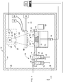
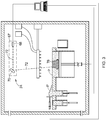
- FIG. 1 illustrates schematically an example of one type of suitable apparatus 10 for carrying out an additive manufacturing method as described herein.
- Basic components of the exemplary apparatus 10 include a table 12, a build platform 14 surrounded by a build chamber 16, a particulate material supply 18, an overflow container 20, a binder applicator 22, and a radiant energy apparatus 24.
- the components of the apparatus 10 may be surrounded by a housing 26, which may be used to provide a shielding or inert gas atmosphere using gas ports 28. Each of these components will be described in more detail below.
- the table 12 is a rigid structure defining a planar worksurface 30.
- the worksurface 30 is coplanar with and defines a virtual workplane. In the illustrated example, it includes a build opening 32 communicating with the build chamber 16 and exposing the build platform 14 and a supply opening 34 communicating with the particulate material supply 18.
- the plane of the worksurface 30 may be considered to be oriented parallel to an X-Y plane of the apparatus 10, and a direction perpendicular to the X-Y plane is denoted as a Z-direction (X, Y, and Z being three mutually perpendicular directions).
- Means may be provided for moving the build platform 14 parallel to the Z-direction.
- these means are depicted schematically as a simple actuator 36, with the understanding devices such as pneumatic cylinders, hydraulic cylinders, ballscrew electric actuators, or linear electric actuators may be used for this purpose.
- the particulate material supply 18 may be any device or combination of devices which is operable to apply a layer of particulate material "P" to the worksurface and to level the particulate material P.
- the particulate material supply 18 comprises a supply container 38 underlying and communicating with the supply opening 34, and an elevator 40.
- the elevator 40 is a plate-like structure that is vertically slidable within the supply container 38. It is connected to an actuator 42 (shown schematically) operable to selectively move the elevator 40 up or down.
- an actuator 42 shown schematically
- the particulate material supply 18 includes a recoater 44 which is a rigid, laterally-elongated structure that lies on the worksurface 30. It is connected to an actuator 46 (shown schematically) operable to selectively move the recoater 44 along the worksurface 30, to move particulate material P from the supply container 38 and to level it in the build chamber 16. It is noted that there are known configurations for particulate material supply in which a build chamber is not used or required; for example, the build chamber may be simply eliminated, or the apparatus 10 may be used to build sacrificial chamber walls as part of the build process.
- particulate material supplies may be used; for example, one or more rollers (not shown) may be provided to move and level the particulate material P.
- the particulate material may be leveled by vibrating the build chamber 16.
- particulate material P may be applied by dropping it into the build chamber 16 by an overhead device (not shown).
- it may be provided with means for movement parallel to the Z-axis, and the build platform 14 may remain stationary during the build process.
- the binder applicator 22 may be any device or combination of devices which is operable to apply a layer of binder B over the particulate material P in the build chamber 16. In contrast to prior art hardware and methods, the boundaries of the applied binder do not define the boundaries of the completed component, therefore the binder applicator 22 need not be capable of applying the binder with any specific level of accuracy.
- the binder applicator 22 may be configured to apply binder B over the entire exposed surface area of the particulate material P, or it may be configured to apply binder B over a smaller, predetermined area, as described in more detail below. In either case, the binder B is generally applied such that there is more surface area of binder applied than there will be surface area of cured binder.
- Nonlimiting examples of suitable binder application devices include chutes, hoppers, pumps, spray nozzles, spraybars, or precision spraying devices such as inkjet printheads.
- FIGS. 1 and 2 show one possible configuration of the binder applicator 22.
- a spraybar 48 carrying a plurality of spaced-apart spray nozzles 50 is mounted above the build chamber 16.
- a supply of a suitable binder is contained in a binder reservoir 52 which is connected in fluid communication with the spraybar 48.
- the spraybar 48 may incorporate valving enabling the spray nozzles 50 to be opened or closed individually or in one or more groups.
- the spraybar 48 is mounted to an actuator 54 permitting selective motion along an axis perpendicular to the long axis of the spraybar 48 and parallel to the worksurface 30 (e.g. the Y-axis). Coordinated operation of the spray nozzles 50 and the actuator 54 will permit the application of binder over the build chamber 16 in arbitrary patterns.
- the radiant energy apparatus 24 may comprise any device or combination of devices operable to generate and project radiant energy on the particulate material P in a suitable pattern and with a suitable energy level and other operating characteristics to cure the binder B during the build process, described in more detail below.
- the radiant energy apparatus 24 may comprise a "projector" 56, used herein generally to refer to any device operable to generate a radiant energy patterned image of suitable energy level and other operating characteristics to cure the binder B.
- patterned image refers to a projection of radiant energy comprising an array of individual pixels.
- Nonlimiting examples of patterned imaged devices include a Digital Light Processing (“DLP") projector or another digital micromirror device, a 2D array of LEDs, a 2D array of lasers, or optically addressed light valves.
- DLP Digital Light Processing
- the projector 56 comprises a radiant energy source 58 such as a UV lamp, an image forming apparatus 60 operable to receive a source beam 62 from the radiant energy source 58 and generate a patterned image 64 to be projected onto the surface of the particulate material P, and optionally focusing optics 66, such as one or more lenses.
- a radiant energy source 58 such as a UV lamp
- an image forming apparatus 60 operable to receive a source beam 62 from the radiant energy source 58 and generate a patterned image 64 to be projected onto the surface of the particulate material P
- optionally focusing optics 66 such as one or more lenses.
- the radiant energy source 58 may comprise any device operable to generate a beam of suitable energy level and frequency characteristics to cure the binder B.
- the radiant energy source 58 comprises a UV flash lamp.
- the image forming apparatus 60 may include one or more mirrors, prisms, and/or lenses and is provided with suitable actuators, and arranged so that the source beam 62 from the radiant energy source 58 can be transformed into a pixelated image in an X-Y plane coincident with the worksurface 30.
- the image forming apparatus 60 may be a digital micromirror device.
- the projector 56 may be a commercially-available DLP projector.
- the radiant energy apparatus 24 may comprise a "scanned beam apparatus" 67, used herein to refer generally to refer to any device operable to generate one or more radiant energy beams of suitable energy level and other operating characteristics to cure the binder B and to scan the beam (or beams) over the worksurface 30 in a desired pattern.
- the scanned beam apparatus 67 comprises a radiant energy source 68 and a beam steering apparatus 70.
- the radiant energy source 68 may comprise any device operable to generate a beam of suitable power and other operating characteristics to cure the binder.
- suitable radiant energy sources include lasers or electron beam guns.
- the beam steering apparatus 70 may include one or more mirrors, prisms, and/or lenses and provided with suitable actuators, and arranged so that a beam 72 from the radiant energy source 68 can be focused to a desired spot size and steered to a desired position in plane coincident with the worksurface 30.
- the beam 72 may be referred to herein as a "build beam".
- Other types of scanned beam apparatus may be used. For example, scanned beam sources using multiple build beams are known, as are scanned beam sources in which the radiant energy source itself is movable by way of one or more actuators.
- the apparatus 10 may include a controller 74.
- the controller 74 in FIG. 1 is a generalized representation of the hardware and software required to control the operation of the apparatus 10, including some or all of the particulate material supply 18, the binder applicator 22, the radiant energy apparatus 24, and the various actuators described above.
- the controller 74 may be embodied, for example, by software running on one or more processors embodied in one or more devices such as a programmable logic controller (“PLC”) or a microcomputer.
- PLC programmable logic controller
- Such processors may be coupled to sensors and operating components, for example, through wired or wireless connections.
- the same processor or processors may be used to retrieve and analyze sensor data, for statistical analysis, and for feedback control.
- the particulate material P literally comprises particles, which are conventionally defined as "a very small bit of matter".
- the particulate material P may comprise any material which can be laid down in a substantially flat layer and which is chemically and physically compatible with the selected binder.
- the term "powder”, conventionally defined as “dry material made up of fine particles”, may be considered a synonym for the term particulate material.
- the resolution of the apparatus and the process is related to the particle size of the particulate material P.
- the particles may be regular or irregular in shape, may be uniform or non-uniform in size, and may have variable aspect ratios.
- the particles may take the form of small spheres or granules, or may be shaped like small rods or fibers.
- composition of the particulate material P may be selected as desired to suit a particular application.
- the particulate material P may be metallic, ceramic, polymeric, and/or organic. Mixtures of different compositions may be used.
- the particulate material may be "fusible”, meaning it is capable of consolidation into a mass upon further processing, such as sintering via application of heat and/or pressure.
- fusibility is a characteristic of many available ceramic and metallic powders.
- the binder B comprises a material which is radiant-energy curable and which is capable of adhering or binding together the particulate material P in the cured state.
- radiant-energy curable refers to any material which solidifies in response to the application of radiant energy of a particular frequency and energy level.
- the binder B may comprise a known type of photopolymer resin containing photo-initiator compounds functioning to trigger a polymerization reaction, causing the resin to change from a liquid state to a solid state.
- the binder B may comprise a material which contains a solvent that may be evaporated out by the application of radiant energy.
- the uncured binder B may be provided in solid, liquid, or vapor form.
- composition of the binder B may be selected as desired to suit a particular application. Mixtures of different compositions may be used.
- the binder B may be selected to have the ability to out-gas or burn off during further processing, such as the sintering process described above.
- the component 76 is software modeled as a stack of planar layers arrayed along the Z-axis. Depending on the type of curing method used, each layer may be divided into a grid of pixels. The actual component 76 may be modeled and/or manufactured as a stack of dozens or hundreds of layers. Suitable software modeling processes are known in the art.
- the apparatus 10 is positioned to define a selected layer increment.
- the build platform 14 may be positioned below the worksurface 30 by a selected layer increment.
- the layer increment affects the speed of the additive manufacturing process and the resolution of the component 76.
- the layer increment can be variable, with a larger layer increment being used to speed the process in portions of a component 76 not requiring high accuracy, and a smaller layer increment being used where higher accuracy is required, at the expense of process speed.
- the particulate material supply 18 is used to deposit particulate material P, without binder, over the build platform 14.
- the elevator 40 of the supply container 38 may be raised to push particulate material P through the supply opening 34, exposing it above the worksurface 30.
- the recoater 44 is moved across the worksurface 30 to spread the raised particulate material P horizontally over the build platform 14 and to form a level surface. Any excess particulate material P drops into the overflow container 20 as the recoater 44 passes from left to right. Subsequently, the recoater 44 may be moved back to a starting position.
- the leveled particulate material P may be referred to as a "build layer” and the exposed upper surface thereof may be referred to as a "build surface”.
- Other known types of particulate material supply utilize a recoater arm which moves above the build platform, not relying on a worksurface to ride upon.
- different layers may comprise two or more particulate materials.
- one layer may comprise particulate material of a first composition
- a second layer may comprise particulate material of a second composition.
- the different particulate materials may be provided, for example, by providing one or more additional particulate material supply containers 78, as seen in FIG. 1 .
- any of the layers may comprise two or more particulate materials.
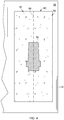
- FIG. 4 illustrates an exemplary layer 80 showing a cross-section of the component 76 superimposed thereupon.
- the layer 80 is divided into a first section 82 including particulate material of a first composition, and a second section 84 including particulate material of a second composition.
- a dashed line 86 indicates the division between the two sections 82, 84.
- the shape, size, and number of sections, and number of different particulate material compositions within a given layer may be arbitrarily selected. If multiple particulate materials are used in one layer, then the deposition steps described above would be carried out for each section of the layer.
- binder B is applied over the particulate material P, using the binder applicator 22.
- binder applicator 22 For example, if a liquid binder B is used, it may be discharged from the spray nozzles 50 of the spraybar 48 as the spraybar is traversed across the build surface.
- the surface area of the binder B applied is larger than the surface area of the cross-section that will eventually be cured.
- binder B is applied over the surface of the exposed particulate material P in a selected area 88 ( FIG. 2 ) that is generally uniform over the majority of the platform 14, and may cover the entire platform 14.
- the selected area 88 may be somewhat smaller than the size of the build chamber 16.
- binder B would be applied over the surface of the exposed particulate material P in a selected area 90 tailored to the cross-section of the component 76 being built, for the specific layer under consideration.
- the selected area 90 may be a regular shape such as a polygon having minimum dimensions slightly larger than the maximum dimensions of the component cross-sectional area in each axis.
- the selected area 90 may be an arbitrary or irregular shape generally following the outermost perimeter of the component cross-section, with an additional marginal boundary 92. This shape may be described as roughly approximating the shape of the component cross-section.
- the second option may be referred to as a "gross" or “rough” or “coarse” application of binder, these terms referring to the level of accuracy achieved. It will be understood that this gross, rough, or coarse application of binder may be achievable using a simple spraybar apparatus as described above and need not require the use of a conventional printhead apparatus. Alternatively, this gross, rough, or coarse application of binder may be achieved using a conventional printhead apparatus (not shown).
- different layers may comprise two or more binders of different compositions.
- one layer may comprise a binder of a first composition
- a second layer may comprise a binder of a second composition.
- the different binders may be provided, for example, by providing one or more additional binder reservoirs 94 coupled to the spraybar 48, as seen in FIG. 1 . Additional options for the use of two different binders are described in more detail below.
- the particulate material P would be premixed with binder B, then loaded into the particulate material supply 18, and the particulate material supply 18 would be used to deposit the mixture of the particulate material and the binder B over the build platform 14.
- premixed refers to a mechanical mixture of particulate material and binder, as well as to particulate material in which the constituent particles have been coated with a layer of a binder.
- different layers may have different particulate material compositions, or individual layers may include multiple sections with different particulate material compositions.
- the radiant energy apparatus 24 is used to cure a two-dimensional cross-section or layer of the component 76 being built.
- the projector 56 projects a patterned image 64 representative of the cross-section of the component 76 on the surface of the binder-coated particulate material P. Exposure to the radiant energy cures and solidifies the pattern in the binder B. This type of curing is referred to herein as "selective" curing. Another layer increment is defined, for example by the platform 14 being moved vertically downward by the layer increment, and particulate material P and binder B are applied as described above. The projector 56 again projects a patterned image 64. Exposure to the radiant energy cures and solidifies the pattern in the binder B and joins it to the previously-cured layer below. This cycle of incrementing a layer, applying particulate material P and binder B, and then curing the binder B is repeated until the entire component 76 is complete.
- the radiant energy source 68 emits a beam 72 and the beam steering apparatus 70 is used to selectively cure the binder B by steering a focal spot of the build beam 72 over the exposed particulate material P and binder B in an appropriate pattern. Exposure to the radiant energy cures and solidifies the pattern in the binder B.
- Another layer increment is defined, for example by the build platform 14 being moved vertically downward by the layer increment, and another layer of particulate material P and binder B is applied in a similar thickness.
- the radiant energy source 68 again emits a build beam 72 and the beam steering apparatus 70 is used to steer the focal spot of the build beam 72 over the exposed particulate material P in an appropriate pattern.
- the exposed layer of the particulate material P is exposed to the radiant energy which cures and solidifies the pattern in the binder B and joins it to the previously-cured layer below.
- This cycle of incrementing a layer, applying particulate material P and binder B, and then curing the binder B is repeated until the entire workpiece W is complete.
- a scanned beam apparatus may be used in combination with a projector.
- a scanned beam apparatus may be used to apply radiant energy (in addition to that applied by the projector) by scanning one or multiple beams over the surface of the exposed particulate material P. This may be concurrent or sequential with the use of the projector.
- the process described above does not involve re-melting of the previously cured layer.
- percentage of cure of the binder B depends upon how much radiant energy is applied.
- the binder B may exhibit an exponential characteristic in a curing versus energy curve. Accordingly, when a multi-layer component is made using this type of binder B, the energy output of the radiant energy apparatus 24 may be carefully selected to partially cure or "under-cure" an underlying layer, with the expectation that when the subsequent layer is applied, the energy from that next layer will complete the curing of the lower layer.
- the accuracy of either process is primarily related to the particle size of the particulate material P and the resolution of the projector 56 or scanned beam apparatus 67.
- Either curing method results in a component 74 in which the particulate material P is held in a solid shape by the cured binder B.
- a polymeric binder B if a polymeric binder B is used, the result of the multilayer process is a cured filled polymer with a very high percentage of fill. This may be referred to as a "green" component.
- This green component may be usable as an end product for low-temperature conditions.
- the green component may be removed from the build chamber 16, and excess particulate material P and/or uncured binder B may be removed and potentially reused.
- the component 76 may be treated to conventional sintering process to burn out the binder B and to consolidate the ceramic or metallic particles.
- a known infiltration process may be carried out during or after the sintering process, in order to fill voids in the component with a material having a lower melting temperature than the particulate material P. The infiltration process improves component physical properties.
- first and second binders may be provided, with the first being curable using a first wavelength of radiant energy, and the second binder being curable using a second wavelength of radiant energy.
- first and second binders may be provided, with the first being curable using a particular wavelength of radiant energy, and the second binder being curable by exposure to high temperature (e.g.
- the radiant energy apparatus 24 may be configured to apply radiant energy at different wavelengths, or more than one radiant energy apparatus 24 may be provided in the apparatus 10, or a radiant energy apparatus 24 as described above may be combined with another type of curing apparatus intended to produce nonselective or uniform curing results, such as radiant heating elements, quartz lamps, etc. These types of curing apparatus do not apply radiant energy in a pattern as described above but rather subjective the entire build chamber 16 to radiant energy.
- the different binders may be incorporated as part of the binder application steps described above. Alternatively, either or both of the binders may be incorporated as part of a premix as described above.
- At least one of the binders is provided by a pre-mixture or is applied before a first curing step is carried out.
- the remaining binders may be applied before or after curing steps are carried out.
- At least one of the binders is selectively cured as described above.
- the remaining binders can be selectively cured or uniformly cured.
- first binder may be used to help connect the particles that will form the final component
- second binder may be used as a support structure to give the component strength through the build process.
- the method described herein has several advantages over the prior art. In particular, it permits economically viable production of components with fine feature fidelity; provides freedom in the choice of materials; works at high speed; and has low cost.
- One specific advantage of the gross binder application process is that it should make it easier to reuse or recycle uncured particulate material in the areas that have not been sprayed with binder.
Landscapes
- Engineering & Computer Science (AREA)
- Chemical & Material Sciences (AREA)
- Materials Engineering (AREA)
- Manufacturing & Machinery (AREA)
- Mechanical Engineering (AREA)
- Physics & Mathematics (AREA)
- Optics & Photonics (AREA)
- Ceramic Engineering (AREA)
- Structural Engineering (AREA)
- Producing Shaped Articles From Materials (AREA)
Applications Claiming Priority (1)
| Application Number | Priority Date | Filing Date | Title |
|---|---|---|---|
| US15/723,907 US11420384B2 (en) | 2017-10-03 | 2017-10-03 | Selective curing additive manufacturing method |
Publications (1)
| Publication Number | Publication Date |
|---|---|
| EP3470209A1 true EP3470209A1 (de) | 2019-04-17 |
Family
ID=63592636
Family Applications (1)
| Application Number | Title | Priority Date | Filing Date |
|---|---|---|---|
| EP18194596.5A Pending EP3470209A1 (de) | 2017-10-03 | 2018-09-14 | Verfahren zur generativen fertigung mit selektiver härtung |
Country Status (5)
| Country | Link |
|---|---|
| US (1) | US11420384B2 (de) |
| EP (1) | EP3470209A1 (de) |
| JP (1) | JP2019077173A (de) |
| CN (1) | CN109591288A (de) |
| ZA (1) | ZA201806528B (de) |
Cited By (1)
| Publication number | Priority date | Publication date | Assignee | Title |
|---|---|---|---|---|
| EP4237181A4 (de) * | 2020-10-29 | 2024-10-16 | Seurat Technologies, Inc. | Array mit verteiltem fluss |
Families Citing this family (10)
| Publication number | Priority date | Publication date | Assignee | Title |
|---|---|---|---|---|
| CN121716310A (zh) | 2018-01-16 | 2026-03-24 | 佩里多特打印有限责任公司 | 三维打印系统 |
| US11292202B2 (en) * | 2018-06-18 | 2022-04-05 | Hewlett-Packard Development Company, L.P. | Applying an additive manufacturing agent based on actual platform displacement |
| US12103229B2 (en) * | 2019-03-15 | 2024-10-01 | Ricoh Company, Ltd. | Jettable temporary binders to create removable support materials |
| CN110614766A (zh) * | 2019-09-23 | 2019-12-27 | 华中科技大学 | 一种多光束增材制造设备及方法 |
| EP4161718A4 (de) * | 2020-06-08 | 2024-05-29 | Hewlett-Packard Development Company, L.P. | Schichtweise lösungsmittelverdampfung |
| US11642852B2 (en) | 2020-07-01 | 2023-05-09 | International Business Machines Corporation | Rotational material scattering additive manufacturing device |
| US12017298B2 (en) | 2021-08-20 | 2024-06-25 | General Electric Company | Irradiation devices with optical modulators for additively manufacturing three-dimensional objects |
| US12030251B2 (en) | 2021-08-20 | 2024-07-09 | General Electric Company | Irradiation devices with optical modulators for additively manufacturing three-dimensional objects |
| CN115446949B (zh) * | 2022-08-31 | 2024-01-23 | 重庆安都陶瓷有限公司 | 一种陶罐吊装对中系统及方法 |
| US12558846B2 (en) | 2023-03-06 | 2026-02-24 | General Electric Company | Irradiation devices with optical modulators for additively manufacturing three-dimensional objects |
Citations (8)
| Publication number | Priority date | Publication date | Assignee | Title |
|---|---|---|---|---|
| US20020149137A1 (en) * | 2001-04-12 | 2002-10-17 | Bor Zeng Jang | Layer manufacturing method and apparatus using full-area curing |
| US20100323301A1 (en) * | 2009-06-23 | 2010-12-23 | Huey-Ru Tang Lee | Method and apparatus for making three-dimensional parts |
| US20140227123A1 (en) * | 2011-06-01 | 2014-08-14 | Bam Bundesanstalt Fur Materialforschung Und Prufung | Method for producing a moulded body and device |
| WO2014199062A1 (fr) * | 2013-06-11 | 2014-12-18 | Technologies Avancees Et Membranes Industrielles | Procede de fabrication de membranes de filtration par technique additive et membranes obtenues |
| WO2014200595A2 (en) * | 2013-03-15 | 2014-12-18 | 3D Systems, Inc. | Direct writing for additive manufacturing systems |
| CN104859152A (zh) * | 2015-05-25 | 2015-08-26 | 厦门达天电子科技有限公司 | 一种立体模型的成型设备及其成型方法 |
| US20170173886A1 (en) * | 2014-07-13 | 2017-06-22 | Stratasys Ltd. | Method and system for rotational 3d printing |
| US20170246806A1 (en) * | 2014-09-29 | 2017-08-31 | Hewlett-Packard Development Company, L.P. | Generating three-dimensional objects and generating images on substrates |
Family Cites Families (129)
| Publication number | Priority date | Publication date | Assignee | Title |
|---|---|---|---|---|
| US4575330A (en) | 1984-08-08 | 1986-03-11 | Uvp, Inc. | Apparatus for production of three-dimensional objects by stereolithography |
| US4752498A (en) | 1987-03-02 | 1988-06-21 | Fudim Efrem V | Method and apparatus for production of three-dimensional objects by photosolidification |
| US5174931A (en) | 1988-09-26 | 1992-12-29 | 3D Systems, Inc. | Method of and apparatus for making a three-dimensional product by stereolithography |
| US5258146A (en) | 1988-09-26 | 1993-11-02 | 3D Systems, Inc. | Method of and apparatus for measuring and controlling fluid level in stereolithography |
| US5026146A (en) | 1989-04-03 | 1991-06-25 | Hug William F | System for rapidly producing plastic parts |
| US5387380A (en) | 1989-12-08 | 1995-02-07 | Massachusetts Institute Of Technology | Three-dimensional printing techniques |
| US5204055A (en) | 1989-12-08 | 1993-04-20 | Massachusetts Institute Of Technology | Three-dimensional printing techniques |
| US5626919A (en) | 1990-03-01 | 1997-05-06 | E. I. Du Pont De Nemours And Company | Solid imaging apparatus and method with coating station |
| US5096530A (en) | 1990-06-28 | 1992-03-17 | 3D Systems, Inc. | Resin film recoating method and apparatus |
| US5192559A (en) | 1990-09-27 | 1993-03-09 | 3D Systems, Inc. | Apparatus for building three-dimensional objects with sheets |
| US5126529A (en) | 1990-12-03 | 1992-06-30 | Weiss Lee E | Method and apparatus for fabrication of three-dimensional articles by thermal spray deposition |
| US5203944A (en) | 1991-10-10 | 1993-04-20 | Prinz Fritz B | Method for fabrication of three-dimensional articles by thermal spray deposition using masks as support structures |
| JPH07108555B1 (de) | 1992-05-28 | 1995-11-22 | Shiimetsuto Kk | |
| US6146567A (en) | 1993-02-18 | 2000-11-14 | Massachusetts Institute Of Technology | Three dimensional printing methods |
| JP2706611B2 (ja) | 1993-10-14 | 1998-01-28 | 帝人製機株式会社 | 光造形方法および光造形装置 |
| US5496682A (en) | 1993-10-15 | 1996-03-05 | W. R. Grace & Co.-Conn. | Three dimensional sintered inorganic structures using photopolymerization |
| US6206672B1 (en) | 1994-03-31 | 2001-03-27 | Edward P. Grenda | Apparatus of fabricating 3 dimensional objects by means of electrophotography, ionography or a similar process |
| EP0776713B1 (de) | 1995-11-09 | 1999-09-01 | Toyota Jidosha Kabushiki Kaisha | Verfahren zur Herstellung einer Form aus Schichten und damit hergestelltes Gussstück |
| US5660621A (en) | 1995-12-29 | 1997-08-26 | Massachusetts Institute Of Technology | Binder composition for use in three dimensional printing |
| US5697043A (en) | 1996-05-23 | 1997-12-09 | Battelle Memorial Institute | Method of freeform fabrication by selective gelation of powder suspensions |
| US6596224B1 (en) | 1996-05-24 | 2003-07-22 | Massachusetts Institute Of Technology | Jetting layers of powder and the formation of fine powder beds thereby |
| WO1998006560A1 (en) | 1996-08-08 | 1998-02-19 | Sri International | Apparatus for automated fabrication of three-dimensional objects, and associated methods of use |
| US6051179A (en) | 1997-03-19 | 2000-04-18 | Replicator Systems, Inc. | Apparatus and method for production of three-dimensional models by spatial light modulator |
| US5940674A (en) | 1997-04-09 | 1999-08-17 | Massachusetts Institute Of Technology | Three-dimensional product manufacture using masks |
| JPH115254A (ja) | 1997-04-25 | 1999-01-12 | Toyota Motor Corp | 積層造形方法 |
| NL1006059C2 (nl) | 1997-05-14 | 1998-11-17 | Geest Adrianus F Van Der | Werkwijze en inrichting voor het vervaardigen van een vormlichaam. |
| DE19723892C1 (de) | 1997-06-06 | 1998-09-03 | Rainer Hoechsmann | Verfahren zum Herstellen von Bauteilen durch Auftragstechnik |
| US6363606B1 (en) | 1998-10-16 | 2002-04-02 | Agere Systems Guardian Corp. | Process for forming integrated structures using three dimensional printing techniques |
| US6401002B1 (en) | 1999-04-29 | 2002-06-04 | Nanotek Instruments, Inc. | Layer manufacturing apparatus and process |
| US6200646B1 (en) | 1999-08-25 | 2001-03-13 | Spectra Group Limited, Inc. | Method for forming polymeric patterns, relief images and colored polymeric bodies using digital light processing technology |
| WO2001034371A2 (en) | 1999-11-05 | 2001-05-17 | Z Corporation | Material systems and methods of three-dimensional printing |
| US6850334B1 (en) | 2000-01-18 | 2005-02-01 | Objet Geometries Ltd | System and method for three dimensional model printing |
| US6423255B1 (en) * | 2000-03-24 | 2002-07-23 | Rainer Hoechsmann | Method for manufacturing a structural part by deposition technique |
| US20010050031A1 (en) | 2000-04-14 | 2001-12-13 | Z Corporation | Compositions for three-dimensional printing of solid objects |
| US6500378B1 (en) | 2000-07-13 | 2002-12-31 | Eom Technologies, L.L.C. | Method and apparatus for creating three-dimensional objects by cross-sectional lithography |
| ATE381398T1 (de) | 2000-09-25 | 2008-01-15 | Voxeljet Technology Gmbh | Verfahren zum herstellen eines bauteils in ablagerungstechnik |
| US6471800B2 (en) | 2000-11-29 | 2002-10-29 | Nanotek Instruments, Inc. | Layer-additive method and apparatus for freeform fabrication of 3-D objects |
| US6376148B1 (en) | 2001-01-17 | 2002-04-23 | Nanotek Instruments, Inc. | Layer manufacturing using electrostatic imaging and lamination |
| US6896839B2 (en) | 2001-02-07 | 2005-05-24 | Minolta Co., Ltd. | Three-dimensional molding apparatus and three-dimensional molding method |
| GB0103754D0 (en) | 2001-02-15 | 2001-04-04 | Vantico Ltd | Three-dimensional structured printing |
| JP2002292751A (ja) | 2001-03-29 | 2002-10-09 | Minolta Co Ltd | 三次元造形装置及び方法 |
| US6780368B2 (en) | 2001-04-10 | 2004-08-24 | Nanotek Instruments, Inc. | Layer manufacturing of a multi-material or multi-color 3-D object using electrostatic imaging and lamination |
| DE20106887U1 (de) | 2001-04-20 | 2001-09-06 | Envision Technologies GmbH, 45768 Marl | Vorrichtung zum Herstellen eines dreidimensionalen Objekts |
| GB0112675D0 (en) | 2001-05-24 | 2001-07-18 | Vantico Ltd | Three-dimensional structured printing |
| KR20050003356A (ko) * | 2002-04-10 | 2005-01-10 | 후지 샤신 필름 가부시기가이샤 | 노광헤드 및 노광장치와 그 응용 |
| US7270528B2 (en) | 2002-05-07 | 2007-09-18 | 3D Systems, Inc. | Flash curing in selective deposition modeling |
| US7027887B2 (en) | 2002-07-03 | 2006-04-11 | Theries, Llc | Apparatus, systems and methods for use in three-dimensional printing |
| US7087109B2 (en) | 2002-09-25 | 2006-08-08 | Z Corporation | Three dimensional printing material system and method |
| WO2004050323A1 (en) | 2002-12-03 | 2004-06-17 | Objet Geometries Ltd. | Process of and apparatus for three-dimensional printing |
| US8071055B2 (en) | 2002-12-04 | 2011-12-06 | Blue Water Technologies, Inc. | Water treatment techniques |
| US9682425B2 (en) | 2009-12-08 | 2017-06-20 | Baker Hughes Incorporated | Coated metallic powder and method of making the same |
| AU2003900180A0 (en) | 2003-01-16 | 2003-01-30 | Silverbrook Research Pty Ltd | Method and apparatus (dam001) |
| US6966960B2 (en) | 2003-05-07 | 2005-11-22 | Hewlett-Packard Development Company, L.P. | Fusible water-soluble films for fabricating three-dimensional objects |
| EP1475220A3 (de) | 2003-05-09 | 2009-07-08 | FUJIFILM Corporation | Verfahren zur Herstellung eines dreidimensionalen Modells und dreidimensionales Modell |
| US7807077B2 (en) | 2003-06-16 | 2010-10-05 | Voxeljet Technology Gmbh | Methods and systems for the manufacture of layered three-dimensional forms |
| US6930144B2 (en) | 2003-06-24 | 2005-08-16 | Hewlett-Packard Development Company, L.P. | Cement system including a binder for use in freeform fabrication |
| WO2005023524A2 (en) * | 2003-08-29 | 2005-03-17 | Z Corporation | Absorbent fillers for three-dimensional printing |
| DE102004008168B4 (de) | 2004-02-19 | 2015-12-10 | Voxeljet Ag | Verfahren und Vorrichtung zum Auftragen von Fluiden und Verwendung der Vorrichtung |
| JP2005238744A (ja) * | 2004-02-27 | 2005-09-08 | Bridgestone Corp | ブレードの植え込み方法、タイヤ加硫金型及びブレード |
| DE102004012682A1 (de) | 2004-03-16 | 2005-10-06 | Degussa Ag | Verfahren zur Herstellung von dreidimensionalen Objekten mittels Lasertechnik und Auftragen eines Absorbers per Inkjet-Verfahren |
| JP2007537007A (ja) | 2004-05-12 | 2007-12-20 | マサチューセッツ インスティテュート オブ テクノロジー | 溶剤蒸気膜形成を含んだ立体印刷法等の製法 |
| US20060078638A1 (en) | 2004-10-08 | 2006-04-13 | 3D Systems, Inc. | Stereolithographic apparatus |
| US7867302B2 (en) | 2005-02-22 | 2011-01-11 | Saint-Gobain Abrasives, Inc. | Rapid tooling system and methods for manufacturing abrasive articles |
| DE102006038858A1 (de) | 2006-08-20 | 2008-02-21 | Voxeljet Technology Gmbh | Selbstaushärtendes Material und Verfahren zum schichtweisen Aufbau von Modellen |
| US7892474B2 (en) | 2006-11-15 | 2011-02-22 | Envisiontec Gmbh | Continuous generative process for producing a three-dimensional object |
| CN101568422B (zh) | 2006-12-08 | 2013-02-13 | 3D系统公司 | 使用过氧化物固化的三维印刷材料体系和方法 |
| US7968626B2 (en) | 2007-02-22 | 2011-06-28 | Z Corporation | Three dimensional printing material system and method using plasticizer-assisted sintering |
| US8475946B1 (en) | 2007-03-20 | 2013-07-02 | Bowling Green State University | Ceramic article and method of manufacture |
| US8568649B1 (en) | 2007-03-20 | 2013-10-29 | Bowling Green State University | Three-dimensional printer, ceramic article and method of manufacture |
| EP2011631B1 (de) | 2007-07-04 | 2012-04-18 | Envisiontec GmbH | Verfahren und Vorrichtung zum Herstellen eines dreidimensionalen Objekts |
| ES2760927T3 (es) | 2007-07-13 | 2020-05-18 | Advanced Ceramics Mfg Llc | Mandriles basados en áridos para la producción de piezas de material compuesto y métodos de producción de piezas de material compuesto |
| DE102007050679A1 (de) | 2007-10-21 | 2009-04-23 | Voxeljet Technology Gmbh | Verfahren und Vorrichtung zum Fördern von Partikelmaterial beim schichtweisen Aufbau von Modellen |
| DK2052693T4 (da) | 2007-10-26 | 2021-03-15 | Envisiontec Gmbh | Proces og fri-formfabrikationssystem til at fremstille en tredimensionel genstand |
| US8225507B2 (en) | 2008-02-28 | 2012-07-24 | The Aerospace Corporation | Stereolithographic rocket motor manufacturing method |
| US8876513B2 (en) | 2008-04-25 | 2014-11-04 | 3D Systems, Inc. | Selective deposition modeling using CW UV LED curing |
| US8636496B2 (en) | 2008-05-05 | 2014-01-28 | Georgia Tech Research Corporation | Systems and methods for fabricating three-dimensional objects |
| US9561622B2 (en) | 2008-05-05 | 2017-02-07 | Georgia Tech Research Corporation | Systems and methods for fabricating three-dimensional objects |
| CN101303692B (zh) | 2008-06-19 | 2012-08-29 | 徐文和 | 一种供机器语言翻译的通用数码语义库 |
| WO2010045950A1 (de) | 2008-10-20 | 2010-04-29 | Ivoclar Vivadent Ag | Vorrichtung und verfahren zur verarbeitung von lichtpolymerisierbarem material zum schichtweisen aufbau von formkörpern |
| US8741203B2 (en) | 2008-10-20 | 2014-06-03 | Ivoclar Vivadent Ag | Device and method for processing light-polymerizable material for building up an object in layers |
| US8666142B2 (en) | 2008-11-18 | 2014-03-04 | Global Filtration Systems | System and method for manufacturing |
| DE102008058378A1 (de) | 2008-11-20 | 2010-05-27 | Voxeljet Technology Gmbh | Verfahren zum schichtweisen Aufbau von Kunststoffmodellen |
| US8991211B1 (en) | 2009-11-01 | 2015-03-31 | The Exone Company | Three-dimensional printing glass articles |
| WO2011065920A1 (en) | 2009-11-26 | 2011-06-03 | Yu En Tan | Process for building three-dimensional objects |
| IT1397457B1 (it) | 2010-01-12 | 2013-01-10 | Dws Srl | Piastra di modellazione per una macchina stereolitografica, macchina stereolitografica impiegante tale piastra di modellazione e utensile per la pulizia di tale piastra di modellazione. |
| US8211226B2 (en) | 2010-01-15 | 2012-07-03 | Massachusetts Institute Of Technology | Cement-based materials system for producing ferrous castings using a three-dimensional printer |
| JP2011156783A (ja) | 2010-02-02 | 2011-08-18 | Sony Corp | 3次元造形装置、3次元造形物の製造方法及び3次元造形物 |
| IT1400015B1 (it) | 2010-05-17 | 2013-05-09 | Dws Srl | Macchina stereolitografica perfezionata |
| DE102011007957A1 (de) | 2011-01-05 | 2012-07-05 | Voxeljet Technology Gmbh | Vorrichtung und Verfahren zum Aufbauen eines Schichtenkörpers mit wenigstens einem das Baufeld begrenzenden und hinsichtlich seiner Lage einstellbaren Körper |
| WO2012127456A1 (en) | 2011-03-24 | 2012-09-27 | Ramot At Tel-Aviv University Ltd. | Method and devices for solid structure formation by localized microwaves |
| ITVI20110099A1 (it) | 2011-04-20 | 2012-10-21 | Dws Srl | Metodo per la produzione di un oggetto tridimensionale e macchina stereolitografica impiegante tale metodo |
| WO2013019898A1 (en) | 2011-08-01 | 2013-02-07 | The Aerospace Corporation | Systems and methods for casting hybrid rocket motor fuel grains |
| US9944021B2 (en) | 2012-03-02 | 2018-04-17 | Dynamic Material Systems, LLC | Additive manufacturing 3D printing of advanced ceramics |
| US9636873B2 (en) | 2012-05-03 | 2017-05-02 | B9Creations, LLC | Solid image apparatus with improved part separation from the image plate |
| EP2671706A1 (de) | 2012-06-04 | 2013-12-11 | Ivoclar Vivadent AG | Verfahren zum Aufbau eines Formkörpers |
| US8888480B2 (en) | 2012-09-05 | 2014-11-18 | Aprecia Pharmaceuticals Company | Three-dimensional printing system and equipment assembly |
| FR3000698B1 (fr) | 2013-01-09 | 2015-02-06 | Phidias Technologies | Fabrication d'un objet en volume par lithographie, a resolution spatiale amelioree |
| US9528011B2 (en) | 2013-01-11 | 2016-12-27 | Ceraloc Innovation Ab | Digital binder and powder print |
| US9498920B2 (en) | 2013-02-12 | 2016-11-22 | Carbon3D, Inc. | Method and apparatus for three-dimensional fabrication |
| WO2014126834A2 (en) | 2013-02-12 | 2014-08-21 | Eipi Systems, Inc. | Method and apparatus for three-dimensional fabrication with feed through carrier |
| EP2969482B1 (de) | 2013-03-15 | 2018-05-09 | 3D Systems, Inc. | Dreidimensionales druckmaterialsystem |
| US9931785B2 (en) | 2013-03-15 | 2018-04-03 | 3D Systems, Inc. | Chute for laser sintering systems |
| JP6257185B2 (ja) | 2013-06-28 | 2018-01-10 | シーメット株式会社 | 三次元造形装置及び三次元造形物の造形方法 |
| JP2015016610A (ja) | 2013-07-10 | 2015-01-29 | ローランドディー.ジー.株式会社 | 画像投影システムおよび画像投影方法 |
| US9360757B2 (en) | 2013-08-14 | 2016-06-07 | Carbon3D, Inc. | Continuous liquid interphase printing |
| TWI548533B (zh) | 2013-11-20 | 2016-09-11 | 三緯國際立體列印科技股份有限公司 | 立體列印裝置 |
| JP2015139977A (ja) | 2014-01-30 | 2015-08-03 | セイコーエプソン株式会社 | 三次元造形物の製造方法および三次元造形物 |
| US9527244B2 (en) | 2014-02-10 | 2016-12-27 | Global Filtration Systems | Apparatus and method for forming three-dimensional objects from solidifiable paste |
| US20150223921A1 (en) | 2014-02-11 | 2015-08-13 | Brian Kieser | Structurally encoded implantable devices |
| US9487443B2 (en) | 2014-03-14 | 2016-11-08 | Ricoh Company, Ltd. | Layer stack formation powder material, powder layer stack formation hardening liquid, layer stack formation material set, and layer stack object formation method |
| JP6377392B2 (ja) | 2014-04-08 | 2018-08-22 | ローランドディー.ジー.株式会社 | 画像投影システムおよび画像投影方法 |
| CN106804106A (zh) | 2014-05-04 | 2017-06-06 | 亦欧普莱克斯公司 | 多材料三维打印机 |
| JP6606861B2 (ja) | 2014-08-11 | 2019-11-20 | 株式会社リコー | 積層造形用粉末及び積層造形物の製造方法 |
| TWI568601B (zh) | 2014-10-02 | 2017-02-01 | 三緯國際立體列印科技股份有限公司 | 立體列印裝置及其列印方法 |
| TWI630124B (zh) | 2014-11-10 | 2018-07-21 | 三緯國際立體列印科技股份有限公司 | 立體列印裝置 |
| KR101991189B1 (ko) | 2014-12-15 | 2019-06-19 | 휴렛-팩커드 디벨롭먼트 컴퍼니, 엘.피. | 적층 가공 |
| US20160185009A1 (en) | 2014-12-29 | 2016-06-30 | Smith International, Inc. | Additive manufacturing of composite molds |
| CN105254309B (zh) | 2015-09-24 | 2017-11-14 | 佛山华智新材料有限公司 | 一种3d打印陶瓷工艺 |
| CN106584855B (zh) | 2015-10-13 | 2018-09-11 | 三纬国际立体列印科技股份有限公司 | 立体物件成形装置的光源校正方法 |
| CN106584843B (zh) | 2015-10-13 | 2020-03-27 | 三纬国际立体列印科技股份有限公司 | 立体打印装置 |
| EP4137256A1 (de) | 2015-10-30 | 2023-02-22 | Seurat Technologies, Inc. | Verfahren und system zur generativen fertigung |
| JP2017087612A (ja) | 2015-11-12 | 2017-05-25 | セイコーエプソン株式会社 | 三次元造形物の製造装置及び三次元造形物の製造方法 |
| JP6664650B2 (ja) | 2016-01-18 | 2020-03-13 | 国立研究開発法人産業技術総合研究所 | 造形物の製造方法 |
| CA3032821A1 (en) | 2016-08-03 | 2018-02-08 | 3Deo, Inc. | Devices and methods for three-dimensional printing |
| US10632732B2 (en) * | 2016-11-08 | 2020-04-28 | 3Dbotics, Inc. | Method and apparatus for making three-dimensional objects using a dynamically adjustable retaining barrier |
| US10800108B2 (en) * | 2016-12-02 | 2020-10-13 | Markforged, Inc. | Sinterable separation material in additive manufacturing |
| US11554418B2 (en) * | 2017-03-17 | 2023-01-17 | Desktop Metal, Inc. | Base plate in additive manufacturing |
| US11123796B2 (en) * | 2017-04-28 | 2021-09-21 | General Electric Company | Method of making a pre-sintered preform |
| JP7185829B2 (ja) * | 2019-02-20 | 2022-12-08 | セイコーエプソン株式会社 | 三次元造形物の製造方法 |
-
2017
- 2017-10-03 US US15/723,907 patent/US11420384B2/en active Active
-
2018
- 2018-09-14 EP EP18194596.5A patent/EP3470209A1/de active Pending
- 2018-09-14 JP JP2018172078A patent/JP2019077173A/ja active Pending
- 2018-09-20 CN CN201811100508.3A patent/CN109591288A/zh active Pending
- 2018-10-02 ZA ZA2018/06528A patent/ZA201806528B/en unknown
Patent Citations (8)
| Publication number | Priority date | Publication date | Assignee | Title |
|---|---|---|---|---|
| US20020149137A1 (en) * | 2001-04-12 | 2002-10-17 | Bor Zeng Jang | Layer manufacturing method and apparatus using full-area curing |
| US20100323301A1 (en) * | 2009-06-23 | 2010-12-23 | Huey-Ru Tang Lee | Method and apparatus for making three-dimensional parts |
| US20140227123A1 (en) * | 2011-06-01 | 2014-08-14 | Bam Bundesanstalt Fur Materialforschung Und Prufung | Method for producing a moulded body and device |
| WO2014200595A2 (en) * | 2013-03-15 | 2014-12-18 | 3D Systems, Inc. | Direct writing for additive manufacturing systems |
| WO2014199062A1 (fr) * | 2013-06-11 | 2014-12-18 | Technologies Avancees Et Membranes Industrielles | Procede de fabrication de membranes de filtration par technique additive et membranes obtenues |
| US20170173886A1 (en) * | 2014-07-13 | 2017-06-22 | Stratasys Ltd. | Method and system for rotational 3d printing |
| US20170246806A1 (en) * | 2014-09-29 | 2017-08-31 | Hewlett-Packard Development Company, L.P. | Generating three-dimensional objects and generating images on substrates |
| CN104859152A (zh) * | 2015-05-25 | 2015-08-26 | 厦门达天电子科技有限公司 | 一种立体模型的成型设备及其成型方法 |
Cited By (1)
| Publication number | Priority date | Publication date | Assignee | Title |
|---|---|---|---|---|
| EP4237181A4 (de) * | 2020-10-29 | 2024-10-16 | Seurat Technologies, Inc. | Array mit verteiltem fluss |
Also Published As
| Publication number | Publication date |
|---|---|
| US20190099942A1 (en) | 2019-04-04 |
| JP2019077173A (ja) | 2019-05-23 |
| CN109591288A (zh) | 2019-04-09 |
| US11420384B2 (en) | 2022-08-23 |
| ZA201806528B (en) | 2019-07-31 |
Similar Documents
| Publication | Publication Date | Title |
|---|---|---|
| US11420384B2 (en) | Selective curing additive manufacturing method | |
| EP3466649B1 (de) | Verfahren zur generativen fertigung mit selektivem sintern | |
| US11707888B2 (en) | Method and apparatus for additive manufacturing with shared components | |
| US11945157B2 (en) | Multi-material additive manufacturing apparatus and method | |
| JP7032543B2 (ja) | 粉末分注を用いた付加製造 | |
| US11446860B2 (en) | Method and apparatus for separation of cured resin layer from resin support in additive manufacturing | |
| US11590691B2 (en) | Plate-based additive manufacturing apparatus and method | |
| JP2022525122A (ja) | 作動マイクロピクセレーションおよび動的密度制御を用いた物体のデジタル製造のための方法および装置 | |
| US10821668B2 (en) | Method for producing a component layer-by- layer | |
| CN107848202A (zh) | 用于制造三维物体的方法和装置 | |
| US20190126535A1 (en) | Cartridge plate-based additive manufacturing apparatus and method | |
| US20220063191A1 (en) | Method of joining additively manufactured components | |
| CN107835738B (zh) | 用于制备三维物体的方法和装置 | |
| US20190322038A1 (en) | Apparatus and method for fabrication with curable resins by extrusion and photo curing | |
| JP7515816B2 (ja) | 成形装置及び成形体の製造方法 |
Legal Events
| Date | Code | Title | Description |
|---|---|---|---|
| PUAI | Public reference made under article 153(3) epc to a published international application that has entered the european phase |
Free format text: ORIGINAL CODE: 0009012 |
|
| STAA | Information on the status of an ep patent application or granted ep patent |
Free format text: STATUS: THE APPLICATION HAS BEEN PUBLISHED |
|
| AK | Designated contracting states |
Kind code of ref document: A1 Designated state(s): AL AT BE BG CH CY CZ DE DK EE ES FI FR GB GR HR HU IE IS IT LI LT LU LV MC MK MT NL NO PL PT RO RS SE SI SK SM TR |
|
| AX | Request for extension of the european patent |
Extension state: BA ME |
|
| STAA | Information on the status of an ep patent application or granted ep patent |
Free format text: STATUS: REQUEST FOR EXAMINATION WAS MADE |
|
| 17P | Request for examination filed |
Effective date: 20191015 |
|
| RBV | Designated contracting states (corrected) |
Designated state(s): AL AT BE BG CH CY CZ DE DK EE ES FI FR GB GR HR HU IE IS IT LI LT LU LV MC MK MT NL NO PL PT RO RS SE SI SK SM TR |
|
| GRAP | Despatch of communication of intention to grant a patent |
Free format text: ORIGINAL CODE: EPIDOSNIGR1 |
|
| STAA | Information on the status of an ep patent application or granted ep patent |
Free format text: STATUS: GRANT OF PATENT IS INTENDED |
|
| INTG | Intention to grant announced |
Effective date: 20191205 |
|
| GRAJ | Information related to disapproval of communication of intention to grant by the applicant or resumption of examination proceedings by the epo deleted |
Free format text: ORIGINAL CODE: EPIDOSDIGR1 |
|
| STAA | Information on the status of an ep patent application or granted ep patent |
Free format text: STATUS: REQUEST FOR EXAMINATION WAS MADE |
|
| INTC | Intention to grant announced (deleted) | ||
| STAA | Information on the status of an ep patent application or granted ep patent |
Free format text: STATUS: EXAMINATION IS IN PROGRESS |
|
| 17Q | First examination report despatched |
Effective date: 20200703 |