EP3470593A1 - Raccord en t permettant de relier des profils et profil permettant de recevoir le raccord en t - Google Patents
Raccord en t permettant de relier des profils et profil permettant de recevoir le raccord en t Download PDFInfo
- Publication number
- EP3470593A1 EP3470593A1 EP17461621.9A EP17461621A EP3470593A1 EP 3470593 A1 EP3470593 A1 EP 3470593A1 EP 17461621 A EP17461621 A EP 17461621A EP 3470593 A1 EP3470593 A1 EP 3470593A1
- Authority
- EP
- European Patent Office
- Prior art keywords
- profile
- connector
- recess
- port
- peg
- Prior art date
- Legal status (The legal status is an assumption and is not a legal conclusion. Google has not performed a legal analysis and makes no representation as to the accuracy of the status listed.)
- Granted
Links
Images




Classifications
-
- E—FIXED CONSTRUCTIONS
- E06—DOORS, WINDOWS, SHUTTERS, OR ROLLER BLINDS IN GENERAL; LADDERS
- E06B—FIXED OR MOVABLE CLOSURES FOR OPENINGS IN BUILDINGS, VEHICLES, FENCES OR LIKE ENCLOSURES IN GENERAL, e.g. DOORS, WINDOWS, BLINDS, GATES
- E06B3/00—Window sashes, door leaves, or like elements for closing wall or like openings; Layout of fixed or moving closures, e.g. windows in wall or like openings; Features of rigidly-mounted outer frames relating to the mounting of wing frames
- E06B3/96—Corner joints or edge joints for windows, doors, or the like frames or wings
- E06B3/964—Corner joints or edge joints for windows, doors, or the like frames or wings using separate connection pieces, e.g. T-connection pieces
- E06B3/9642—Butt type joints with at least one frame member cut off square; T-shape joints
-
- E—FIXED CONSTRUCTIONS
- E04—BUILDING
- E04B—GENERAL BUILDING CONSTRUCTIONS; WALLS, e.g. PARTITIONS; ROOFS; FLOORS; CEILINGS; INSULATION OR OTHER PROTECTION OF BUILDINGS
- E04B2/00—Walls, e.g. partitions, for buildings; Wall construction with regard to insulation; Connections specially adapted to walls
- E04B2/88—Curtain walls
- E04B2/96—Curtain walls comprising panels attached to the structure through mullions or transoms
- E04B2/965—Connections of mullions and transoms
-
- E—FIXED CONSTRUCTIONS
- E06—DOORS, WINDOWS, SHUTTERS, OR ROLLER BLINDS IN GENERAL; LADDERS
- E06B—FIXED OR MOVABLE CLOSURES FOR OPENINGS IN BUILDINGS, VEHICLES, FENCES OR LIKE ENCLOSURES IN GENERAL, e.g. DOORS, WINDOWS, BLINDS, GATES
- E06B3/00—Window sashes, door leaves, or like elements for closing wall or like openings; Layout of fixed or moving closures, e.g. windows in wall or like openings; Features of rigidly-mounted outer frames relating to the mounting of wing frames
- E06B3/96—Corner joints or edge joints for windows, doors, or the like frames or wings
- E06B3/964—Corner joints or edge joints for windows, doors, or the like frames or wings using separate connection pieces, e.g. T-connection pieces
- E06B3/968—Corner joints or edge joints for windows, doors, or the like frames or wings using separate connection pieces, e.g. T-connection pieces characterised by the way the connecting pieces are fixed in or on the frame members
- E06B3/9687—Corner joints or edge joints for windows, doors, or the like frames or wings using separate connection pieces, e.g. T-connection pieces characterised by the way the connecting pieces are fixed in or on the frame members with screws blocking the connecting piece inside or on the frame member
-
- E—FIXED CONSTRUCTIONS
- E06—DOORS, WINDOWS, SHUTTERS, OR ROLLER BLINDS IN GENERAL; LADDERS
- E06B—FIXED OR MOVABLE CLOSURES FOR OPENINGS IN BUILDINGS, VEHICLES, FENCES OR LIKE ENCLOSURES IN GENERAL, e.g. DOORS, WINDOWS, BLINDS, GATES
- E06B3/00—Window sashes, door leaves, or like elements for closing wall or like openings; Layout of fixed or moving closures, e.g. windows in wall or like openings; Features of rigidly-mounted outer frames relating to the mounting of wing frames
- E06B3/96—Corner joints or edge joints for windows, doors, or the like frames or wings
- E06B3/964—Corner joints or edge joints for windows, doors, or the like frames or wings using separate connection pieces, e.g. T-connection pieces
- E06B3/968—Corner joints or edge joints for windows, doors, or the like frames or wings using separate connection pieces, e.g. T-connection pieces characterised by the way the connecting pieces are fixed in or on the frame members
- E06B3/98—Corner joints or edge joints for windows, doors, or the like frames or wings using separate connection pieces, e.g. T-connection pieces characterised by the way the connecting pieces are fixed in or on the frame members the connecting pieces being specially adapted for drawing the frame members towards each other
-
- F—MECHANICAL ENGINEERING; LIGHTING; HEATING; WEAPONS; BLASTING
- F16—ENGINEERING ELEMENTS AND UNITS; GENERAL MEASURES FOR PRODUCING AND MAINTAINING EFFECTIVE FUNCTIONING OF MACHINES OR INSTALLATIONS; THERMAL INSULATION IN GENERAL
- F16B—DEVICES FOR FASTENING OR SECURING CONSTRUCTIONAL ELEMENTS OR MACHINE PARTS TOGETHER, e.g. NAILS, BOLTS, CIRCLIPS, CLAMPS, CLIPS OR WEDGES; JOINTS OR JOINTING
- F16B7/00—Connections of rods or tubes, e.g. of non-circular section, mutually, including resilient connections
- F16B7/04—Clamping or clipping connections
- F16B7/044—Clamping or clipping connections for rods or tubes being in angled relationship
- F16B7/0446—Clamping or clipping connections for rods or tubes being in angled relationship for tubes using the innerside thereof
- F16B7/0453—Clamping or clipping connections for rods or tubes being in angled relationship for tubes using the innerside thereof the tubes being drawn towards each other
-
- F—MECHANICAL ENGINEERING; LIGHTING; HEATING; WEAPONS; BLASTING
- F16—ENGINEERING ELEMENTS AND UNITS; GENERAL MEASURES FOR PRODUCING AND MAINTAINING EFFECTIVE FUNCTIONING OF MACHINES OR INSTALLATIONS; THERMAL INSULATION IN GENERAL
- F16B—DEVICES FOR FASTENING OR SECURING CONSTRUCTIONAL ELEMENTS OR MACHINE PARTS TOGETHER, e.g. NAILS, BOLTS, CIRCLIPS, CLAMPS, CLIPS OR WEDGES; JOINTS OR JOINTING
- F16B7/00—Connections of rods or tubes, e.g. of non-circular section, mutually, including resilient connections
- F16B7/18—Connections of rods or tubes, e.g. of non-circular section, mutually, including resilient connections using screw-thread elements
- F16B7/187—Connections of rods or tubes, e.g. of non-circular section, mutually, including resilient connections using screw-thread elements with sliding nuts or other additional connecting members for joining profiles provided with grooves or channels
Definitions
- the present invention relates to a T-connector for connecting two profiles at an angle, especially connecting two profiles at a right angle.
- a T-connector for connecting two profiles at an angle, especially connecting two profiles at a right angle.
- the T-connectors are used for connecting profiles that form support construction for a glass panels.
- the construction for a glass panel usually bears heavy loads and is exposed to changeable ambient temperature. Since the glass panels usually form terminal surface of the building, thus, the construction is exposed to the internal ambient temperature and external ambient temperature at the same time. The difference between the external and internal ambient temperature values is usually considerable. Temperature of different and changeable value acting on the construction may causes changes of dimensions of metal components of the construction, which makes the construction not tight, thus a leakage in the construction for a glass panel may occur. The leakage in the construction for a glass panel causes that air and water might be present inside the construction. The presence of water and air is highly undesirable, since water and air cause corrosion when they appear inside of the construction.
- the metal components of the construction comprises profile and T-connector for connecting the profiles.
- EP1795665 discloses T-joint for jointing two profiles (i.e. struts) at the right angle.
- the T-joint is fastened within a terminate part of one profile and then connect to a wall of the other profile.
- a body of the T-joint comprises two parts. A first, main part, which is fixed in a profile and a second part which is separated from the above mentioned first part. The first part and the second part form together the T-joint.
- the T-joint of the type described above is generally complex. A position of the movable second part of the T-joint may be changed with respect to the first part making the connection between the profile and the T-joint arranged improperly. Thus, the T-joint is not properly clamped within the profile such that fastening of the T-joint inside the profile is no longer assured.
- T-joint Another disadvantage of such a T-joint is assembly of the T-joint within a profile, which is time-consuming, since not only the first part of the T-joint needs to be positioned within the profile but also the movable second part needs to be arranged with respect to the profile and the first, main part of the T-joint.
- the two parts need to be positioned not only with respect to the profile but also with respect to each other. This makes the assembly of the profiles more time consuming.
- the probability of incorrectly assembling the profiles and the T-joint with respect to each other is significant.
- T-joint connecting two profiles.
- the T-joint comprises a peg (i.e. pen) which works in conjunction with an opening in the other profile.
- the profile can move in the body of the T-joint between the rest position whereby the above-mentioned peg is pushed out of the guide and pushed-in position.
- the peg is provided with springy elements and the peg hooks behind the wall of the other profile. After one end of the peg is hooked behind the wall then the other end of the peg is fixed in the T-joint thus providing connection between the peg and the other profile.
- the disadvantage of the prior art solution is that the length of the connection between the T-joint and the other profile cannot be regulated i.e. adjusted. This is because the peg of the T-joint may take only a predetermined position with respect to the T-joint and the other profile. Thus, a play between the peg of the T-joint and the other profile may occurs.
- This situation is very common, since in practice, the profiles have dimensions which are uneven along the length of the profile. This irregularity in dimensions results from inaccuracy in manufacture, and/or inaccuracy of positioning the T-joint in the profile and/or inaccuracy in cutting the profile and/or inaccuracy in positioning the profile.
- the two profiles are connected by the T-joint with a play between the peg of the T-joint and the second profile.
- the connection between profiles is susceptible to the potential leakage.
- the present invention provides a T-connector and a profile for receiving the T-connector.
- a T-connector for fastening within a profile for connecting a first profile with a second profile at an angle
- the T-connector comprising a body shaped so that the body is axially fastenable within the first profile, the body is provided with a longitudinal recess provided in axial direction of the body, the recess constitutes a first part of a port for receiving fastening means for fastening the T-connector within the first profile, and the longitudinal recess provided in the body is shaped for cooperating with a longitudinal recess which constitutes a second part of the port provided in the first profile, thus when the T-connector is provided within the first profile, the recess formed in the T-connector and the recess in the profile form a complete port for receiving the fastening means.
- An advantage of the T-connector according to the invention is that the T-connector is simple in construction and easy to assembly and provide high connection strength.
- the T-connector and the profile are connected directly. i.e. no additional elements, except fastening means are required. Therefore, a risk of incorrect positioning of the T-connector within the profile is reduced and improving accuracy of positioning the T-connector in the profile is achieved. Moreover, a number of elements required for assembling is reduced, making assembling of the T-connector less time consuming and cheaper.
- the T-connector according to the invention provides strong connection which is less susceptible to a leakage.
- the body is provided with two recesses, each recess is arranged at the corner area of the body suitable for inserting into a corresponding corners of the first profile.
- Arranging the recesses of the T-connector in the corner area of the body is easy to manufactured and provides the most preferred connection between the T-connector and the profile.
- the recess provided in the body constituting the first part of the port is shaped so that the recess forms substantially a half of the port for receiving the fastening means.
- the recess in the T-connector is complementary to the recess in a profile and forms substantially a half of the port for receiving connecting means, the process of assembling of the T-connector and the profile is very easy and provides the most durable connection. Moreover, the recess is easy to manufacture both in the T-connector and in the profile. In addition, the port is provided only at ends of the profile, whereas the ends of the profile are in locations, where the port is actually needed. As a result, less material is used for manufacturing the profile.
- the recess provided in the T-connector may also provide less or more than a half of the port.
- the recess provided in the T-connector may form about 40% of circumference of the port.
- the recess provided in the profile form about 60 % of circumference of the port.
- the recess provided in the body when cooperates with the recess provided in the profile forms together the port in the form of longitudinal opening.
- the recess provided in the body has a widen portion for facilitating location of fastening means into the port, the widen portion is located at an entry of the recess which first receive the fastening means during assembly.
- the T-connector is made of metal, preferably zinc and aluminum based alloys.
- the T-connector is cut from a longitudinal aluminum profile.
- the recess provided in the body when cooperating with the recess provided in the profile form a port suitable for receiving a thread-forming screw.
- the port is configured for receiving a thread-forming screw, no thread need to be formed in a body of a T-connector, neither in the profile.
- the T- connector comprises the body provided with a hole arranged in the axial direction of the body, and in the hole connecting means for connecting the first profile with the second profile are provided, the connecting means comprise:
- a T-connector for fastening within a profile for connecting a first profile with a second profile at an angle
- the T-connector comprises a body shaped so that the body is axially fastenable within the first profile.
- the body is provided with a hole arranged in the axial direction of the body, and in the hole connecting means for connecting the first profile with the second profile are provided, the connecting means comprise:
- the T-connector according to the invention provides that a position of the peg can be regulated, i.e. adjusted to a real distance between the T-connector and the second profile.
- the peg hooks the wall of the opening provided in the second profile.
- the peg is fixed with respect to the T-connector and the second profile.
- the T-connector is especially advantageous for the profiles having uneven dimensions along the length of the profiles.
- the T-connector according to the invention provides that, irrespective of the irregularity in dimensions of the profiles and imperfection of relative position between two profiles, the position of the peg of the T-connector with respect to the second profile is fixed without play. Therefore, the position of the first profile with the T-connector is fixed with respect to the second profile. Since a play between the peg of the T-connector and the second profile is avoided, the connection is fixed and high tightness of the connection is achieved.
- a profile provided with means for receiving a T- connector for connecting two profiles at an angle.
- the profile is shaped so that the internal adjacent corners of the profile form a recess which constitute a second part of a port for receiving fastening means for fastening the T-connector within the profile and the recess provided in the profile is shaped so that is suitable for cooperating with a recess provided in the body which constitute a first part of the port provided in the T-connector, thus the recess provided in the T-connector forms with the recess provided in the profile a complete port for receiving the fastening means when the T-connector is provided within the first profile.
- the recess formed in the profile being a second part of the port for receiving connection means results in that an additional material of the profile is formed along to the profile. Thanks to the fact that the port is formed along the whole length of the profile, the port increases stiffness of the whole profile, increasing thereby the stiffness of the whole structure.
- the profile may be cut from a longitudinal profile and cut to a desired length at any point while keeping its advantageous feature of being complementary in shape to the T-connector. Thus, no additional components or operations are required in order to receive the T-connector in the profile according to the invention.
- corners are the most overrigid area of the profile, arranging the recess formed in the profile in the corners reduce a risk of forming a deformation of the profile.
- each second recess is arranged inside the profile in two adjacent corners within the profile.
- An advantage of the profile according to the invention is that the recess forming the second part of the port for receiving connecting means is arranged in corners which are adjacent to the back wall of the profile, thus the recess reinforces the profile in the area of the port which is subjected to high loads in the structure for glass panels.
- This reinforcement is especially advantage since the reinforcement increases stiffness of the profile both along the profile and crosswise the profile.
- the recess provided in the profile is arranged at the terminate parts of the first profile suitable for receiving the T-connector.
- the material of the profile is saved.
- the terminate parts of the profile increase stiffness of the profile at locations which are subjected to the highest loads.
- the recess provided in the profile is arranged only at the terminate parts of the first profile suitable for receiving the T-connector.
- the second part of the port is suitable for receiving a thread-forming screw when cooperating with the second part of the port.
- Providing the recess configured for receiving a thread-forming screw makes the process of manufacturing the profile easier, since no thread needs to be formed in the profile.
- Forming the recess being the second part of the port as configured for receiving a thread forming screw makes the manufacture of the profile simpler and cheaper.
- the configuration suitable for receiving the thread forming screw is for example realized as longitudinal grooves shaped in substantially rounded internal corner of the profile. This is especially advantageous since forming the part of the port as longitudinal grooves is very easy to manufacture.
- a system for connecting a first profile with a second profile at the angle comprising the profile according to the invention and the T-connector according to the invention.
- the system according to the present invention enjoys all benefits and advantages of the T-connector and the profile according to the invention.
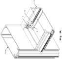
- Fig. 1A shows a T-connector 1 according to the present invention.
- the T-connector 1 comprises a body 2.
- the body 2 is shaped so that the body 2 can be axially inserted and fastened within a first profile 4.
- first and second concerning profiles are used only in purpose to distinguish between a profile in which the T-connector is mounted and a profile to which the T-connector is attached. In practice the first profile and the second profile may have the same structure and may be mounted in the way around.
- the body 2 is configured to be inserted into the first profile 4 axially, i.e. along longitudinal direction of the first profile 4, indicated with arrow A in the Fig. 1A and Fig. 1B .
- the terms "longitudinal" concerning the direction in the T-connector, as used within the present disclosure, is the direction of the T-connector parallel to the main axis of a profile, when mounted within the profile.
- the body 2 comprises two longitudinal recesses 6. Each recess 6 forms a first part of a port 12 (shown on Fig. 2 ) for receiving fastening means 11 for fastening the T-connector 1 within the profile 4.
- Each recess 6 is arranged along the preferably along the whole length of the T-connector 1.
- the recess provided in the T-connector 1 is provided only along a part of length of the T-connector, which means that the recess does not extend through the body 2 of the T-connector.
- Each recess 6 is arranged in corner area of the T-connector 1, as shown in Fig. 1A .
- the corner areas of the T-connector 1 are parts of the T-connector 1 located in the extremity of the T-connector 1 which are located adjacent to the corner area of the first profile when the T-connector is arranged within the first profile 4.
- the second part of the port 12 is formed by a longitudinal recess 7 comprised in the first profile 4.
- first profile 4 two recesses 7 are provided.
- Each recess 7 is provided in a corner area of the first profile 4 respectively, as shown in Fig. 1A .
- the corner area of the first profile 4 are arranged in an area where rear wall of the first profile 4 contacts with side walls of the first profile 4.
- the recess 7 is shaped along the length of the first profile 4, preferably along the whole length of the first profile 4.
- the recess 7 provided in the profile 4 when cooperates with the recess 6 provided in the body 2 of the T-connector 1 forms the port 12 for receiving fastening means 11.
- Fig. 2 shows side view of the T-connector according to the invention when the T-connector 1 is fixed within the profile 4.
- the recess 6 forming the first part of the port 12 provided in the body 2 is located adjacent to the recesses 7 constituting the second parts of the port 12 formed in the first profile 4.
- the recess 6 provided in the body 2 with the recess 7 provided in the first profile forms together the port 12 for receiving the fastening means 11, as shown in Fig. 2 .
- the fastening means 11 are introduced to each port 12 as shown in Fig.2 .
- the fastening means 11 are thread-forming screw.
- the T-connector 1 is positioned in the profile 4 at a terminate part of the profile 4.
- the fastening means 11 are screwed into the port 12 the T-connector 1 is fixed within the first profile 4.
- the port 12 has a shape of a longitudinal opening.
- the fastening means 11 are preferably screw, as shown for example on Fig. 1A and Fig. 1B , more preferably thread-forming screw.
- the screw comprise a head.
- the head of the screw has diameter smaller than diameter of the screw.
- the fastening means 11, preferably thread-forming screw are screwed into the port 12 thus fastening the T-connector 1 within the first profile 4.
- the T-connector 2 also comprises positioning means for positioning the T-connector 1 within the first profile 4.
- exemplary positioning means are at least one groove 8 shaped along in the longitudinal direction of the body 2. Each groove 8 receives longitudinal projection 9 formed within the first profile 4.
- the first profile 4 is connected with the second profile 5 via connecting means provided with the T-connector 1.
- the connecting means engage the first profile 4 with the second profile 5.
- Fig. 3 shows an exploded view of the first profile 4 and the second profile 5 with the T-connector 1.
- a connecting means comprising a peg 13, spring means 14 and a bolt 3 are used.
- the connecting means are arranged in a through hole 20 provided in the body 2 of the T-connector 1.
- the bolt 3 cooperates with the peg 13 in such a way that the bolt 3 adjusts a position of the peg 13 with respect to the second profile 5.
- the peg 13 comprises a cavity 16.
- the cavity 16 is configured to be hooked over an edge 18 of an opening 15 in the second profile 5.
- the hooking is realized in the following way: the peg 13 is inserted to the opening 15 provided in the second profile 5.
- the cavity 16 of the peg 13 is positioned in front of the edge 18 of the opening 15.
- the edge 18 of the opening 15 is then inserted into the cavity 16.
- the position of the peg 13 is adjusted by the bolt 3 to the distance between the body 2 of the T-connector 1 and the second profile 5, providing thereby the connection between the first profile 4 and the second profile 5 is provided without play.
- the bolt 3 is screwed through the T-connector to the peg 13.
- the spring means 14 in the form of a spring are provided.
- the bolt 3 is screw into the peg 13 in order to fix first profile 4 with respect to the second profile 5 and provide connection without play between the profiles. Since the bolt 3 is threaded the regulation is continuous. Thus, the fixing is performed with very high accuracy.
- the first profile 4 is fixed to the second profile 5 via typical fixing pins 17.
- Fig. 4A and Fig. 4B depicts a cross-section of the first profile 4 and the second profile 5 with the T-connector 1 when assembled.
- Fig. 4A shows enlarged view of cross-section- of the T-connector 1 when assembled.
- the threaded bolt 3 is arranged inside opening 20 of the T-connector 1.
- the bolt 3 comprises bolt head 25 which protrudes from opening 20 at regulatory side 22 of the T-connector 1.
- the bolt 3 is screwed into the peg 13 arranged on a peg side 23 of the T-connector 1.
- the peg side 23 of the T-connector 1 is a side which is faced to the second profile 5.
- the peg 13 comprises a receiving hole 26 for receiving the bolt 3.
- the receiving hole 26 is threaded.
- the receiving hole 26 receives an end of the threaded bolt 3.
- the edge 18 of the opening 15 is accommodated within the cavity 16 when assembled.
- the cavity 16 is configured for receiving the edge 18 of the wall of the second profile 5 in order to allow accommodating the edge 18 within the cavity 16.
- the peg 13 is at least partially arranged inside the T-connector 1 as shown in Fig. 4A and Fig. 4B .
- the external shape of the peg 13 corresponds to the shape the opening 20 of the T-connector 1 on the peg side 23 of the T-connector 1.
- the shape of the peg 13 is also clearly shown on Fig. 1A , Fig.1B , and Fig. 3 .
- the movement of the peg 13 is performed by screwing the bolt 3 into the peg 13.
- the cavity 16 of the peg 13 hook over the edge 18 of the opening 15 and fixes a position of the first profile 4 with respect to the second profile 5. Since the position of the peg 13 is adjustable in a continuous manner with respect to the second profile 5, the position of the peg 13 is changeable very precisely. Therefore, the peg 13 is hooked on the edge 18 of the opening 18 without a play and fixes connection without play between the profiles.
- the hole 20 provided in the body 2 of the T-connector 1 extends through the body 2 in longitudinal direction of the body 2.
- the hole 20 has round cross-section at a regulatory side 22 of the body 2.
- the regulatory side 22 of the body 2 is a side from which the bolt 3 is screwed.
- the peg side 23 is a side of the body from which the peg 13 protrudes from the hole 20 and is inserted to the opening 15 provided in the second profile 5.
- a cross section of the hole 20 at the peg side 23 of the body 2 has cut circle shape. Since the shape of the peg 13 is also cut circle shape and in use, the peg 13 is at least partially accommodated in the opening 20, the peg 12 is not able to turn in the opening 20.
- the hole 20 at the regulatory side 22 has round cross-section, as shown in Fig. 5A-C and 6A-C , the bolt 3 can be screwed directly through the opening 20 provided in the body 2 into the peg 13.
- the T-connector according to the first embodiment of the invention can be manufactured for example by casting.
- the first embodiment of the T-connector 1 according to the invention is shown in detail in Fig. 5a, Fig. 5b, Fig. 5c .
- the recesses 6 are preferably provided with a widen portion 19 shown in detail in Fig. 5b and Fig. 5c .
- the widen portion 19 is a portion at an entry of the recess 6 which is a part which receives the fastening means 11 as a first during assembly. The widen portion 19 facilitates inserting the fastening means 11 into the port 12.
- Fig. 1B shows T-connector 1 according to the second embodiment of the invention.
- the T-connector 1 has constant cross-section along the whole longitudinal length.
- the opening 20 has the constant cross-section at the peg side 23 of the body 2 and the regulatory side 22 of the body 2.
- Second embodiment of the T-connector 1 according to the invention is shown in detail in Fig. 6a, Fig. 6b, Fig. 6c . Since the T-connector according to the second embodiment has constant cross-section, the T-connector 1 according to the second embodiment may be manufactured as being cut from a T-shaped profile having constant cross-section. As a consequence, the opening 20 has a shape of a cut circle at the whole length. Thus, there is a need to provide a self- centering nut 24 at regulatory side 22 of the opening 20 in order to screw the bolt 3.
Landscapes
- Engineering & Computer Science (AREA)
- Civil Engineering (AREA)
- Structural Engineering (AREA)
- General Engineering & Computer Science (AREA)
- Architecture (AREA)
- Mechanical Engineering (AREA)
- Physics & Mathematics (AREA)
- Electromagnetism (AREA)
- Mutual Connection Of Rods And Tubes (AREA)
Priority Applications (4)
| Application Number | Priority Date | Filing Date | Title |
|---|---|---|---|
| HUE17461621A HUE063393T2 (hu) | 2017-10-16 | 2017-10-16 | Profilból és összekötõ T-szerkezetbõl álló rendszer profilok összekapcsolásához |
| PL17461621.9T PL3470593T3 (pl) | 2017-10-16 | 2017-10-16 | System profilu i łącznika typu t do łączenia profili |
| ES17461621T ES2957885T3 (es) | 2017-10-16 | 2017-10-16 | Un sistema de un perfil y un conector en T para conectar perfiles |
| EP17461621.9A EP3470593B8 (fr) | 2017-10-16 | 2017-10-16 | Système d' un profil et un raccord en t permettant de relier des profils |
Applications Claiming Priority (1)
| Application Number | Priority Date | Filing Date | Title |
|---|---|---|---|
| EP17461621.9A EP3470593B8 (fr) | 2017-10-16 | 2017-10-16 | Système d' un profil et un raccord en t permettant de relier des profils |
Publications (4)
| Publication Number | Publication Date |
|---|---|
| EP3470593A1 true EP3470593A1 (fr) | 2019-04-17 |
| EP3470593C0 EP3470593C0 (fr) | 2023-07-19 |
| EP3470593B1 EP3470593B1 (fr) | 2023-07-19 |
| EP3470593B8 EP3470593B8 (fr) | 2023-09-13 |
Family
ID=60119985
Family Applications (1)
| Application Number | Title | Priority Date | Filing Date |
|---|---|---|---|
| EP17461621.9A Active EP3470593B8 (fr) | 2017-10-16 | 2017-10-16 | Système d' un profil et un raccord en t permettant de relier des profils |
Country Status (4)
| Country | Link |
|---|---|
| EP (1) | EP3470593B8 (fr) |
| ES (1) | ES2957885T3 (fr) |
| HU (1) | HUE063393T2 (fr) |
| PL (1) | PL3470593T3 (fr) |
Cited By (1)
| Publication number | Priority date | Publication date | Assignee | Title |
|---|---|---|---|---|
| EA038005B1 (ru) * | 2020-02-12 | 2021-06-22 | Совместное Общество С Ограниченной Ответственностью "Алюминтехно" | Т-образное соединение вертикального и горизонтального профилей стоечно-ригельной системы и закладной элемент |
Citations (4)
| Publication number | Priority date | Publication date | Assignee | Title |
|---|---|---|---|---|
| DE4210456A1 (de) * | 1992-03-30 | 1993-10-07 | Helmuth Kahl | Querverbindung für Profilstäbe mittels Zuggliedern |
| EP1020575A2 (fr) * | 1999-01-18 | 2000-07-19 | SCHÜCO International KG | Connection en T entre un poteau et une traverse profilés d'une façade ou d'une toiture vitrée |
| EP1795665A2 (fr) | 2005-12-12 | 2007-06-13 | Reynaers Aluminium, naamloze vennootschap | Assemblage en T |
| EP2767664A2 (fr) * | 2013-02-15 | 2014-08-20 | Alcoa Aluminium Deutschland, Inc. | Dispositif de fixation, procédé d'équipement d'une partie de cadre avec un profilé de traverse au moyen d'un dispositif de fixation et système de profilé doté d'un dispositif de fixation |
Family Cites Families (3)
| Publication number | Priority date | Publication date | Assignee | Title |
|---|---|---|---|---|
| IT1392619B1 (it) * | 2009-01-20 | 2012-03-16 | Bortoluzzi Mobili Srl | Sistema di formazione universale di telai metallici, particolarmente per ante di mobili. |
| DE202010015317U1 (de) * | 2010-11-12 | 2011-01-27 | Siegenia-Aubi Kg | Eckverbindung |
| US9366072B1 (en) * | 2015-02-23 | 2016-06-14 | Jose Humberto Orozco Aguayo | Adjustable screen frame assembly |
-
2017
- 2017-10-16 PL PL17461621.9T patent/PL3470593T3/pl unknown
- 2017-10-16 HU HUE17461621A patent/HUE063393T2/hu unknown
- 2017-10-16 ES ES17461621T patent/ES2957885T3/es active Active
- 2017-10-16 EP EP17461621.9A patent/EP3470593B8/fr active Active
Patent Citations (4)
| Publication number | Priority date | Publication date | Assignee | Title |
|---|---|---|---|---|
| DE4210456A1 (de) * | 1992-03-30 | 1993-10-07 | Helmuth Kahl | Querverbindung für Profilstäbe mittels Zuggliedern |
| EP1020575A2 (fr) * | 1999-01-18 | 2000-07-19 | SCHÜCO International KG | Connection en T entre un poteau et une traverse profilés d'une façade ou d'une toiture vitrée |
| EP1795665A2 (fr) | 2005-12-12 | 2007-06-13 | Reynaers Aluminium, naamloze vennootschap | Assemblage en T |
| EP2767664A2 (fr) * | 2013-02-15 | 2014-08-20 | Alcoa Aluminium Deutschland, Inc. | Dispositif de fixation, procédé d'équipement d'une partie de cadre avec un profilé de traverse au moyen d'un dispositif de fixation et système de profilé doté d'un dispositif de fixation |
Cited By (1)
| Publication number | Priority date | Publication date | Assignee | Title |
|---|---|---|---|---|
| EA038005B1 (ru) * | 2020-02-12 | 2021-06-22 | Совместное Общество С Ограниченной Ответственностью "Алюминтехно" | Т-образное соединение вертикального и горизонтального профилей стоечно-ригельной системы и закладной элемент |
Also Published As
| Publication number | Publication date |
|---|---|
| EP3470593C0 (fr) | 2023-07-19 |
| EP3470593B1 (fr) | 2023-07-19 |
| EP3470593B8 (fr) | 2023-09-13 |
| PL3470593T3 (pl) | 2024-03-18 |
| ES2957885T3 (es) | 2024-01-29 |
| HUE063393T2 (hu) | 2024-01-28 |
Similar Documents
| Publication | Publication Date | Title |
|---|---|---|
| US9790689B2 (en) | Baluster connector | |
| US20170233996A1 (en) | Connectors and methods of fabricating the same | |
| US10391591B2 (en) | Jig for firearm lower receiver manufacture | |
| EP3604728B1 (fr) | Joint pour cadre metallique | |
| US9695591B2 (en) | Beam reinforcing structure | |
| BR112015030603B1 (pt) | Tubo de andaime e elemento de andaime | |
| EP3470593B1 (fr) | Système d' un profil et un raccord en t permettant de relier des profils | |
| KR101061905B1 (ko) | 센서 지지 브라켓 및 그 조립체 | |
| EP2246578A1 (fr) | Élément connecteur intermédiaire | |
| US9708813B2 (en) | Beam reinforcing metallic material and beam reinforcing structure | |
| US9926971B2 (en) | Omni-directional connection assembly | |
| US11327332B2 (en) | Repeatable precision mounting of mechanical parts | |
| GB2039659A (en) | Coupling device for furniture panels | |
| US12049915B2 (en) | Split coupler for pipes | |
| CN110935768B (zh) | 一种弯管机芯棒快换工装和更换方法 | |
| EP2228550A1 (fr) | Barre de tenon et jonction de tenon | |
| GB2590892A (en) | A joint for a fenestration unit | |
| CN210381050U (zh) | 车载摄像头 | |
| CN210087759U (zh) | 紧固机构 | |
| CN221857222U (zh) | 一种型材连接件 | |
| CN221270174U (zh) | A型架底座条框焊接定位装置及a型架 | |
| CN219175668U (zh) | 一种装配式预制钢筋的连接结构 | |
| CN107610601B (zh) | 显示屏 | |
| CN211009495U (zh) | 带定位功能的螺钉柱及其配合件 | |
| US10781847B2 (en) | Threaded pin and system comprising a threaded pin and a holder |
Legal Events
| Date | Code | Title | Description |
|---|---|---|---|
| PUAI | Public reference made under article 153(3) epc to a published international application that has entered the european phase |
Free format text: ORIGINAL CODE: 0009012 |
|
| STAA | Information on the status of an ep patent application or granted ep patent |
Free format text: STATUS: THE APPLICATION HAS BEEN PUBLISHED |
|
| AK | Designated contracting states |
Kind code of ref document: A1 Designated state(s): AL AT BE BG CH CY CZ DE DK EE ES FI FR GB GR HR HU IE IS IT LI LT LU LV MC MK MT NL NO PL PT RO RS SE SI SK SM TR |
|
| AX | Request for extension of the european patent |
Extension state: BA ME |
|
| STAA | Information on the status of an ep patent application or granted ep patent |
Free format text: STATUS: REQUEST FOR EXAMINATION WAS MADE |
|
| 17P | Request for examination filed |
Effective date: 20191016 |
|
| RBV | Designated contracting states (corrected) |
Designated state(s): AL AT BE BG CH CY CZ DE DK EE ES FI FR GB GR HR HU IE IS IT LI LT LU LV MC MK MT NL NO PL PT RO RS SE SI SK SM TR |
|
| RAP1 | Party data changed (applicant data changed or rights of an application transferred) |
Owner name: HYDRO BUILDING SYSTEMS POLAND SP. Z O.O. |
|
| STAA | Information on the status of an ep patent application or granted ep patent |
Free format text: STATUS: EXAMINATION IS IN PROGRESS |
|
| 17Q | First examination report despatched |
Effective date: 20210330 |
|
| GRAP | Despatch of communication of intention to grant a patent |
Free format text: ORIGINAL CODE: EPIDOSNIGR1 |
|
| STAA | Information on the status of an ep patent application or granted ep patent |
Free format text: STATUS: GRANT OF PATENT IS INTENDED |
|
| INTG | Intention to grant announced |
Effective date: 20230208 |
|
| GRAS | Grant fee paid |
Free format text: ORIGINAL CODE: EPIDOSNIGR3 |
|
| GRAA | (expected) grant |
Free format text: ORIGINAL CODE: 0009210 |
|
| STAA | Information on the status of an ep patent application or granted ep patent |
Free format text: STATUS: THE PATENT HAS BEEN GRANTED |
|
| AK | Designated contracting states |
Kind code of ref document: B1 Designated state(s): AL AT BE BG CH CY CZ DE DK EE ES FI FR GB GR HR HU IE IS IT LI LT LU LV MC MK MT NL NO PL PT RO RS SE SI SK SM TR |
|
| REG | Reference to a national code |
Ref country code: GB Ref legal event code: FG4D |
|
| REG | Reference to a national code |
Ref country code: CH Ref legal event code: EP |
|
| REG | Reference to a national code |
Ref country code: DE Ref legal event code: R096 Ref document number: 602017071430 Country of ref document: DE |
|
| REG | Reference to a national code |
Ref country code: IE Ref legal event code: FG4D |
|
| REG | Reference to a national code |
Ref country code: CH Ref legal event code: PK Free format text: BERICHTIGUNG B8 |
|
| RAP4 | Party data changed (patent owner data changed or rights of a patent transferred) |
Owner name: HYDRO BUILDING SYSTEMS POLAND SP. Z O.O. |
|
| U01 | Request for unitary effect filed |
Effective date: 20230819 |
|
| U07 | Unitary effect registered |
Designated state(s): AT BE BG DE DK EE FI FR IT LT LU LV MT NL PT SE SI Effective date: 20230824 |
|
| REG | Reference to a national code |
Ref country code: LT Ref legal event code: MG9D |
|
| U20 | Renewal fee for the european patent with unitary effect paid |
Year of fee payment: 7 Effective date: 20231016 |
|
| PG25 | Lapsed in a contracting state [announced via postgrant information from national office to epo] |
Ref country code: GR Free format text: LAPSE BECAUSE OF FAILURE TO SUBMIT A TRANSLATION OF THE DESCRIPTION OR TO PAY THE FEE WITHIN THE PRESCRIBED TIME-LIMIT Effective date: 20231020 |
|
| PG25 | Lapsed in a contracting state [announced via postgrant information from national office to epo] |
Ref country code: IS Free format text: LAPSE BECAUSE OF FAILURE TO SUBMIT A TRANSLATION OF THE DESCRIPTION OR TO PAY THE FEE WITHIN THE PRESCRIBED TIME-LIMIT Effective date: 20231119 |
|
| REG | Reference to a national code |
Ref country code: HU Ref legal event code: AG4A Ref document number: E063393 Country of ref document: HU |
|
| REG | Reference to a national code |
Ref country code: ES Ref legal event code: FG2A Ref document number: 2957885 Country of ref document: ES Kind code of ref document: T3 Effective date: 20240129 |
|
| PG25 | Lapsed in a contracting state [announced via postgrant information from national office to epo] |
Ref country code: RS Free format text: LAPSE BECAUSE OF FAILURE TO SUBMIT A TRANSLATION OF THE DESCRIPTION OR TO PAY THE FEE WITHIN THE PRESCRIBED TIME-LIMIT Effective date: 20230719 Ref country code: NO Free format text: LAPSE BECAUSE OF FAILURE TO SUBMIT A TRANSLATION OF THE DESCRIPTION OR TO PAY THE FEE WITHIN THE PRESCRIBED TIME-LIMIT Effective date: 20231019 Ref country code: IS Free format text: LAPSE BECAUSE OF FAILURE TO SUBMIT A TRANSLATION OF THE DESCRIPTION OR TO PAY THE FEE WITHIN THE PRESCRIBED TIME-LIMIT Effective date: 20231119 Ref country code: HR Free format text: LAPSE BECAUSE OF FAILURE TO SUBMIT A TRANSLATION OF THE DESCRIPTION OR TO PAY THE FEE WITHIN THE PRESCRIBED TIME-LIMIT Effective date: 20230719 Ref country code: GR Free format text: LAPSE BECAUSE OF FAILURE TO SUBMIT A TRANSLATION OF THE DESCRIPTION OR TO PAY THE FEE WITHIN THE PRESCRIBED TIME-LIMIT Effective date: 20231020 |
|
| REG | Reference to a national code |
Ref country code: DE Ref legal event code: R097 Ref document number: 602017071430 Country of ref document: DE |
|
| PG25 | Lapsed in a contracting state [announced via postgrant information from national office to epo] |
Ref country code: SM Free format text: LAPSE BECAUSE OF FAILURE TO SUBMIT A TRANSLATION OF THE DESCRIPTION OR TO PAY THE FEE WITHIN THE PRESCRIBED TIME-LIMIT Effective date: 20230719 Ref country code: RO Free format text: LAPSE BECAUSE OF FAILURE TO SUBMIT A TRANSLATION OF THE DESCRIPTION OR TO PAY THE FEE WITHIN THE PRESCRIBED TIME-LIMIT Effective date: 20230719 Ref country code: CZ Free format text: LAPSE BECAUSE OF FAILURE TO SUBMIT A TRANSLATION OF THE DESCRIPTION OR TO PAY THE FEE WITHIN THE PRESCRIBED TIME-LIMIT Effective date: 20230719 Ref country code: SK Free format text: LAPSE BECAUSE OF FAILURE TO SUBMIT A TRANSLATION OF THE DESCRIPTION OR TO PAY THE FEE WITHIN THE PRESCRIBED TIME-LIMIT Effective date: 20230719 |
|
| PLBE | No opposition filed within time limit |
Free format text: ORIGINAL CODE: 0009261 |
|
| STAA | Information on the status of an ep patent application or granted ep patent |
Free format text: STATUS: NO OPPOSITION FILED WITHIN TIME LIMIT |
|
| PG25 | Lapsed in a contracting state [announced via postgrant information from national office to epo] |
Ref country code: MC Free format text: LAPSE BECAUSE OF FAILURE TO SUBMIT A TRANSLATION OF THE DESCRIPTION OR TO PAY THE FEE WITHIN THE PRESCRIBED TIME-LIMIT Effective date: 20230719 |
|
| 26N | No opposition filed |
Effective date: 20240422 |
|
| U20 | Renewal fee for the european patent with unitary effect paid |
Year of fee payment: 8 Effective date: 20240828 |
|
| PG25 | Lapsed in a contracting state [announced via postgrant information from national office to epo] |
Ref country code: IE Free format text: LAPSE BECAUSE OF NON-PAYMENT OF DUE FEES Effective date: 20231016 |
|
| PG25 | Lapsed in a contracting state [announced via postgrant information from national office to epo] |
Ref country code: IE Free format text: LAPSE BECAUSE OF NON-PAYMENT OF DUE FEES Effective date: 20231016 |
|
| PG25 | Lapsed in a contracting state [announced via postgrant information from national office to epo] |
Ref country code: CY Free format text: LAPSE BECAUSE OF FAILURE TO SUBMIT A TRANSLATION OF THE DESCRIPTION OR TO PAY THE FEE WITHIN THE PRESCRIBED TIME-LIMIT; INVALID AB INITIO Effective date: 20171016 |
|
| U20 | Renewal fee for the european patent with unitary effect paid |
Year of fee payment: 9 Effective date: 20250828 |
|
| PGFP | Annual fee paid to national office [announced via postgrant information from national office to epo] |
Ref country code: PL Payment date: 20250916 Year of fee payment: 9 |
|
| PGFP | Annual fee paid to national office [announced via postgrant information from national office to epo] |
Ref country code: GB Payment date: 20250822 Year of fee payment: 9 |
|
| REG | Reference to a national code |
Ref country code: CH Ref legal event code: U11 Free format text: ST27 STATUS EVENT CODE: U-0-0-U10-U11 (AS PROVIDED BY THE NATIONAL OFFICE) Effective date: 20251101 |
|
| PGFP | Annual fee paid to national office [announced via postgrant information from national office to epo] |
Ref country code: HU Payment date: 20250901 Year of fee payment: 9 |
|
| PG25 | Lapsed in a contracting state [announced via postgrant information from national office to epo] |
Ref country code: TR Free format text: LAPSE BECAUSE OF FAILURE TO SUBMIT A TRANSLATION OF THE DESCRIPTION OR TO PAY THE FEE WITHIN THE PRESCRIBED TIME-LIMIT Effective date: 20230719 |
|
| PGFP | Annual fee paid to national office [announced via postgrant information from national office to epo] |
Ref country code: CH Payment date: 20251101 Year of fee payment: 9 |
|
| PGFP | Annual fee paid to national office [announced via postgrant information from national office to epo] |
Ref country code: ES Payment date: 20251211 Year of fee payment: 9 |