EP3470792A1 - Procédé de diagnostic et dispositif de diagnostic de capteur d'angle de rotation, et dispositif de commande d'actionneur - Google Patents
Procédé de diagnostic et dispositif de diagnostic de capteur d'angle de rotation, et dispositif de commande d'actionneur Download PDFInfo
- Publication number
- EP3470792A1 EP3470792A1 EP17810431.1A EP17810431A EP3470792A1 EP 3470792 A1 EP3470792 A1 EP 3470792A1 EP 17810431 A EP17810431 A EP 17810431A EP 3470792 A1 EP3470792 A1 EP 3470792A1
- Authority
- EP
- European Patent Office
- Prior art keywords
- rotational angle
- angle sensor
- failure
- occurred
- diagnostic apparatus
- Prior art date
- Legal status (The legal status is an assumption and is not a legal conclusion. Google has not performed a legal analysis and makes no representation as to the accuracy of the status listed.)
- Granted
Links
Images







Classifications
-
- G—PHYSICS
- G01—MEASURING; TESTING
- G01D—MEASURING NOT SPECIALLY ADAPTED FOR A SPECIFIC VARIABLE; ARRANGEMENTS FOR MEASURING TWO OR MORE VARIABLES NOT COVERED IN A SINGLE OTHER SUBCLASS; TARIFF METERING APPARATUS; MEASURING OR TESTING NOT OTHERWISE PROVIDED FOR
- G01D3/00—Indicating or recording apparatus with provision for the special purposes referred to in the subgroups
- G01D3/08—Indicating or recording apparatus with provision for the special purposes referred to in the subgroups with provision for safeguarding the apparatus, e.g. against abnormal operation, against breakdown
-
- G—PHYSICS
- G01—MEASURING; TESTING
- G01C—MEASURING DISTANCES, LEVELS OR BEARINGS; SURVEYING; NAVIGATION; GYROSCOPIC INSTRUMENTS; PHOTOGRAMMETRY OR VIDEOGRAMMETRY
- G01C25/00—Manufacturing, calibrating, cleaning, or repairing instruments or devices referred to in the other groups of this subclass
-
- G—PHYSICS
- G01—MEASURING; TESTING
- G01D—MEASURING NOT SPECIALLY ADAPTED FOR A SPECIFIC VARIABLE; ARRANGEMENTS FOR MEASURING TWO OR MORE VARIABLES NOT COVERED IN A SINGLE OTHER SUBCLASS; TARIFF METERING APPARATUS; MEASURING OR TESTING NOT OTHERWISE PROVIDED FOR
- G01D5/00—Mechanical means for transferring the output of a sensing member; Means for converting the output of a sensing member to another variable where the form or nature of the sensing member does not constrain the means for converting; Transducers not specially adapted for a specific variable
- G01D5/12—Mechanical means for transferring the output of a sensing member; Means for converting the output of a sensing member to another variable where the form or nature of the sensing member does not constrain the means for converting; Transducers not specially adapted for a specific variable using electric or magnetic means
- G01D5/14—Mechanical means for transferring the output of a sensing member; Means for converting the output of a sensing member to another variable where the form or nature of the sensing member does not constrain the means for converting; Transducers not specially adapted for a specific variable using electric or magnetic means influencing the magnitude of a current or voltage
- G01D5/20—Mechanical means for transferring the output of a sensing member; Means for converting the output of a sensing member to another variable where the form or nature of the sensing member does not constrain the means for converting; Transducers not specially adapted for a specific variable using electric or magnetic means influencing the magnitude of a current or voltage by varying inductance, e.g. by a movable armature
- G01D5/204—Mechanical means for transferring the output of a sensing member; Means for converting the output of a sensing member to another variable where the form or nature of the sensing member does not constrain the means for converting; Transducers not specially adapted for a specific variable using electric or magnetic means influencing the magnitude of a current or voltage by varying inductance, e.g. by a movable armature by influencing the mutual induction between two or more coils
-
- G—PHYSICS
- G01—MEASURING; TESTING
- G01M—TESTING STATIC OR DYNAMIC BALANCE OF MACHINES OR STRUCTURES; TESTING OF STRUCTURES OR APPARATUS, NOT OTHERWISE PROVIDED FOR
- G01M15/00—Testing of engines
- G01M15/04—Testing internal-combustion engines
- G01M15/042—Testing internal-combustion engines by monitoring a single specific parameter not covered by groups G01M15/06 - G01M15/12
-
- G—PHYSICS
- G01—MEASURING; TESTING
- G01P—MEASURING LINEAR OR ANGULAR SPEED, ACCELERATION, DECELERATION, OR SHOCK; INDICATING PRESENCE, ABSENCE, OR DIRECTION, OF MOVEMENT
- G01P21/00—Testing or calibrating of apparatus or devices covered by the preceding groups
- G01P21/02—Testing or calibrating of apparatus or devices covered by the preceding groups of speedometers
Definitions
- the present invention relates to a diagnostic apparatus and a diagnostic method for a rotational angle sensor, and a control apparatus for an actuator.
- Patent Document 1 JP 2012-145488 A (Patent Document 1), a technique for diagnosing a failure in the rotational angle sensor based on whether or not a sum of a square of a sine wave signal (sin ⁇ ) and a square of a cosine wave signal (cos ⁇ ) corresponding to a rotational angle ⁇ of a rotating body (i.e., sin 2 ⁇ + cos 2 ⁇ ) is within a normal range, has been proposed.
- Patent Document 1 JP 2012-145488 A
- an object of the present invention is to provide a diagnostic apparatus and a diagnostic method for a rotational angle sensor, and to provide a control apparatus for an actuator, which improve normality determination accuracy of the rotational angle sensor.
- a diagnostic apparatus for a rotational angle sensor that outputs two correlated signals, corresponding to a rotational angle, determines whether or not a failure has occurred in the rotational angle sensor based on whether or not a numerical value obtained from the two correlated signals is within a predetermined range. Then, in a case in which the diagnostic apparatus for the rotational angle sensor determines that the failure has occurred in the rotational angle sensor, the diagnostic apparatus cancels the determination that the failure has occurred in the rotational angle sensor, when the numerical value is within the predetermined range and the rotational angle obtained from the two correlated signals is an angle that cannot be recognized to be 0°, 90°, 180°, or 270°.
- a control apparatus for an actuator that rotates a rotating body controlling the actuator so that a rotational angle of the rotating body obtained from an output value of a rotational angle sensor that outputs two correlated signals, corresponding to the rotational angle of the rotating body, converges to a target angle, determines whether or not a failure has occurred in the rotational angle sensor based on whether or not a numerical value obtained from the two correlated signals is within the predetermined range.
- the control apparatus cancels the determination that the failure has occurred in the rotational angle sensor, when the numerical value is within the predetermined range and the rotational angle obtained from the two correlated signals is an angle that cannot be recognized to be 0°, 90°, 180°, or 270°.
- FIG. 1 illustrates an example of an internal combustion engine for use in a vehicle.
- An internal combustion engine 100 includes a cylinder block 110, a piston 120 reciprocatably fitted in a cylinder bore 112 of cylinder block 110, a cylinder head 130 in which an intake port 130A and an exhaust port 130B are formed, and an intake valve 132 and an exhaust valve 134 that open and close opening ends of intake port 130A and exhaust port 130B.
- Piston 120 is coupled to a crankshaft 140 via a con-rod (connecting rod) 150 including a lower link 150A and an upper link 150B.
- a combustion chamber 160 is formed between a top surface 120A of piston 120 and a lower surface of cylinder head 130.
- a spark plug 170 that ignites a mixture of fuel and air is attached to the approximate center of cylinder head 130 defining combustion chamber 160.
- internal combustion engine 100 is provided with a variable valve timing (valve timing control, VTC) mechanism 180 that makes variable the phase of the open period of intake valve 132 relative to crankshaft 140, and a variable compression ratio (VCR) mechanism 190 that makes the compression ratio variable by changing the volume of combustion chamber 160.
- VTC valve timing control
- VCR variable compression ratio
- VTC mechanism 180 advances or retards the center phase of the operating angle of intake valve 132 while keeping the operating angle of intake valve 132 constant.
- VTC mechanism 180 may make variable the phase of at least one of intake valve 132 and exhaust valve 134.
- VCR mechanism 190 makes the compression ratio of internal combustion engine 100 variable.
- VCR mechanism 190 will be described.
- Crankshaft 140 includes a plurality of journal portions 140A and a plurality of crank pin portions 140B. Journal portions 140A are rotatably supported by main bearings (not illustrated) of cylinder block 110. Crank pin portions 140B are eccentric from journal portions 140A, and lower link 150A is rotatably coupled to each of crank pin portions 140B. Upper link 150B has a lower end side pivotally coupled to one end of lower link 150A by a coupling pin 152 and has an upper end side pivotally coupled to piston 120 by a piston pin 154.
- a control link 192 has an upper end side pivotally coupled to the other end of lower link 150A by a coupling pin 194 and has a lower end side pivotally coupled to a lower portion of cylinder block 110 via a control shaft 196.
- control shaft 196 is rotatably supported by the engine body (cylinder block 110) and has an eccentric cam portion 196A that is eccentric from the rotation center of control shaft 196, while a lower end side of control link 192 is rotatably fitted on eccentric cam portion 196A.
- the rotational position of control shaft 196 is controlled by a compression ratio control actuator 198 that uses an electric motor.
- VCR mechanism 190 using such a multi-link mechanism, when control shaft 196 is rotated by compression ratio control actuator 198, the center position of eccentric cam portion 196A, that is, the relative position of eccentric cam portion 196A to the engine body (cylinder block 110), changes.
- the pivotal support position of the lower end of control link 192 is changed by this, the position of piston 120 at the piston top dead center (TDC) becomes higher or lower, so that the volume of combustion chamber 160 increases or decreases, to change the compression ratio of internal combustion engine 100.
- TDC piston top dead center
- control link 192 is rotated relative to eccentric cam portion 196A of control shaft 196 by reciprocating motion of piston 120, so that the compression ratio shifts to the low compression ratio side.
- Stopper mechanism 210 which restricts the displacement (rotation) of control shaft 196 when control shaft 196 is rotated beyond a normal control range, is attached to VCR mechanism 190.
- Stopper mechanism 210 includes a substantially fan-shaped first member 210A, the pivot portion of which is secured to control shaft 196, and a plate-shaped second member 210B secured to cylinder block 110. First member 210A rotates integrally with control shaft 196.
- stopper mechanism 210 When control shaft 196 rotates beyond a maximum compression ratio (upper limit) or a minimum compression ratio (lower limit), defining the normal control range, second member 210B comes in contact with one of two sides defining a central angle of first member 210A, so as to restrict the displacement of control shaft 196, which is one example of a mechanism member.
- stopper mechanism 210 functions when control shaft 196 has exceeded the normal control range, first member 210A and second member 210B do not come in contact with each other in normal control, so that, for example, it is possible to reduce the occurrence of abnormal noise or the like. Stopper mechanism 210 may be used not only for restricting the displacement of control shaft 196, but also for learning a reference position of control shaft 196.
- Stopper mechanism 210 is sufficient if it can restrict the displacement on at least one of the maximum compression ratio side and the minimum compression ratio side with respect to the rotation of control shaft 196. Furthermore, stopper mechanism 210 is sufficient if it can restrict the displacement of control shaft 196 by at least two members, and such two members are not limited to substantially fan-shaped first member 210A and plate-shaped second member 210B, and may have other shapes.
- VTC mechanism 180 and VCR mechanism 190 are electronically controlled by a VTC controller 220 and a VCR controller 230, respectively, each incorporating a processor such as a microcomputer.
- VTC controller 220 and VCR controller 230 are connected to an engine controller 250, incorporating a processor such as a microcomputer and configured to electronically control internal combustion engine 100, via, for example, a controller area network (CAN) 240 being one example of an in-vehicle network. Therefore, freely chosen data can be sent and received via CAN 240 between VTC controller 220, VCR controller 230, and engine controller 250.
- the in-vehicle network is not limited to CAN 240, and any known network such as FlexRay (registered trademark) may be used.
- engine controller 250 To engine controller 250, output signals of a rotational speed sensor 260 that measures rotational speed Ne of internal combustion engine 100, and a load sensor 270 that measures load Q of internal combustion engine 100 are input, as examples of operating states of internal combustion engine 100.
- load Q of internal combustion engine 100 a state quantity closely related to torque, such as intake negative pressure, intake flow rate, supercharging pressure, accelerator opening degree, throttle opening degree, or the like, may be used.
- engine controller 250 refers to maps in which target values matching rotational speeds and loads are set, and calculates a target angle of VTC mechanism 180 and a target compression ratio of VCR mechanism 190 corresponding to rotational speed Ne and load Q of internal combustion engine 100, respectively.
- engine controller 250 sends the target angle and the target compression ratio to VTC controller 220 and VCR controller 230, respectively, via CAN 240.
- Output signals read by engine controller 250 are not limited to the output signals of rotational speed sensor 260 and load sensor 270, and engine controller 250 may read rotational speed Ne and load Q of internal combustion engine 100 from an additional controller (not illustrated) connected via CAN 240.
- VTC controller 220 having received the target angle performs feedback control of a drive current to be output to the actuator of VTC mechanism 180 such that a real angle (actual angle) measured by a sensor (not illustrated) converges to the target angle.
- VCR controller 230 having received the target compression ratio performs feedback control of a drive current to be output to compression ratio control actuator 198 of VCR mechanism 190 such that a real compression ratio (actual compression ratio) that is measured by a compression ratio sensor described below converges to the target compression ratio.
- VTC mechanism 180 and VCR mechanism 190 are controlled to the target values corresponding to the operating state of internal combustion engine 100.
- the compression ratio sensor that measures an actual compression ratio of internal combustion engine 100 includes: a relative angle sensor 280 that measures a relative angle of an output shaft of compression ratio control actuator 198; and an absolute angle sensor 290 that measures an absolute angle of control shaft 196 coupled to the output shaft of compression ratio control actuator 198 via a speed reducer 198A.
- VCR controller 230 uses an output value of absolute angle sensor 290 at the start-up of the engine as a reference point, VCR controller 230 obtains a rotational angle of control shaft 196, that is, the compression ratio of internal combustion engine 100, from an output value of relative angle sensor 280.
- relative angle sensor 280 has high resolution whereas, for example, it cannot distinguish between 0° and 360° of the same phase, and absolute angle sensor 290 can obtain an absolute angle of control shaft 196, although it has low resolution.
- Each of relative angle sensor 280 and absolute angle sensor 290 includes a resolver, or the like, that outputs two correlated signals, corresponding to a rotational angle of a rotating body, more specifically, outputs a sine wave signal and a cosine wave signal.
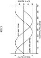
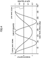
- the resolver includes a rotor that integrally rotates with the rotating body, and a stator with one phase of an exciting coil wound thereon and two phases of output coils wound thereon. When an alternating voltage is applied to the exciting coil of the stator, a two-phase voltage with a sine wave signal and a cosine wave signal, which change in response to the rotational angle (electrical angle) of the rotating body, is generated in each output coil, as illustrated in FIG. 3 .
- VCR controller 230 can obtain the rotational angle of the rotating body. Furthermore, VCR controller 230 obtains a sum of squares of the sine and cosine wave signals output from the resolver, and determines whether or not a failure has occurred in the resolver based on whether or not the sum of squares is within a normal range.
- VCR controller 230 determines that the failure has occurred in the resolver
- VCR controller 230 cancels the determination that the failure has occurred in the resolver, when the sum of squares is within the normal range and the rotational angle of the rotating body is an angle that cannot be recognized to be 0°, 90°, 180°, or 270°.
- VCR controller 230 functions as a diagnostic apparatus for the rotational angle sensor, and a control apparatus for the actuator.
- an upper threshold and a lower threshold are set by adding to or subtracting from the unique value a predetermined value, for example.
- the rotational angle of the rotating body remains at 0° or 180° even when the sum of squares of the sine and cosine wave signals is greater than or equal to the lower threshold, that is, within the normal range, and thus, it will be understood that the normality determination accuracy is insufficient. It should be noted that the same applies to a case in which the sum of squares of the sine and cosine wave signals is less than or equal to the upper threshold, that is, within the normal range (the same applies hereinbelow).
- the rotational angle of the rotating body remains at 90° or 270° even when the sum of squares of the sine and cosine wave signals is greater than or equal to the lower threshold, that is, within the normal range, and thus, it will be understood that the normality determination accuracy is insufficient.
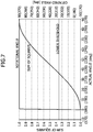
- the determination that a failure has occurred in the resolver was made, it is possible to determine that the determination was erroneously made due to overlapping of noise, or the like, when the sum of squares of the sine and cosine wave signals is within the normal range and the rotational angle of the rotating body obtained from the arctangent of the sine and cosine wave signals is within a range of from 30° to 60°, from 120° to 150°, from 210° to 240°, or from 300° to 330°.
- the range of from -30° (330°) to 30° of the rotational range of the rotating body is given as an example of angles that cannot be recognized that the rotational angle is 0°.
- the ranges of from 60° to 120°, from 150° to 210°, and from 240° to 300° are also given as examples of the angles that cannot be recognized that the rotational angle is 90°, 180°, and 270°, respectively.
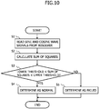
- FIG. 10 illustrates an example of the failure determination process repeatedly executed by a processor of VCR controller 230 at every first predetermined time after the startup of VCR controller 230.
- the failure determination process is terminated when it is determined that a failure has occurred in the resolver.
- step 1 (abbreviated as "S1" in FIG. 10 ; the same applies hereinafter), the processor of VCR controller 230 reads sine and cosine wave signals from the resolver.
- step 2 the processor of VCR controller 230 calculates sum of squares of the sine and cosine wave signals.
- step 3 the processor of VCR controller 230 determines whether or not the sum of squares of the sine and cosine wave signals is greater than or equal to the lower threshold and less than or equal to the upper threshold, that is, whether or not the sum of squares is within the normal range. Then, when the processor of VCR controller 230 determines that the sum of squares is greater than or equal to the lower threshold and less than or equal to the upper threshold, the process proceeds to step 4 (Yes), whereas when the processor determines that the sum of squares is less than the lower threshold or greater than the upper threshold, the process proceeds to step 5 (No).
- step 4 the processor of VCR controller 230 determines that the resolver is normal, that is, no failure has occurred in the resolver.
- step 5 the processor of VCR controller 230 determines that a failure has occurred in the resolver.
- whether or not a failure has occurred in the resolver is determined based on whether or not the sum of squares of the sine and cosine wave signals output from the resolver is within the normal range. Specifically, when the sum of squares of the sine and cosine wave signals is within the normal range, it is determined that the resolver is normal, whereas when the sum of squares is out of the normal range, it is determined that the resolver has failed.
- the processer of VCR controller 230 may output a control signal to compression ratio control actuator 198 of VCR mechanism 190, to cause the transition to fail-safe operation, in which the compression ratio of internal combustion engine 100 is changed to the minimum compression ratio. Furthermore, when determining that the resolver has failed, the processer of VCR controller 230 may shift the rotational angle of the rotating body obtained from the arctangent of the sine and cosine wave signals of the resolver, into the normal range at a freely chosen timing (for example, while the engine is stopped).
- FIG. 11 illustrates an example of the failure determination cancelling process repeatedly executed by the processer of VCR controller 230 at every second predetermined time after the processor determined that the resolver has failed.
- the second predetermined time may be the same as the first predetermined time, or alternatively, may be different from the first predetermined time.
- the execution of the failure determination cancelling process is terminated when the determination indicating that the resolver has failed is cancelled.
- step 11 the processor of VCR controller 230 reads sine and cosine wave signals from the resolver.
- step 12 the processor of VCR controller 230 calculates sum of squares of the sine and cosine wave signals.
- step 13 the processor of VCR controller 230 calculates an arctangent of the sine and cosine wave signals, to obtain the rotational angle of the rotating body.
- step 14 the processor of VCR controller 230 determines whether or not the sum of squares of the sine and cosine wave signals is greater than or equal to the lower threshold and less than or equal to the upper threshold. Then, when the processor of VCR controller 230 determines that the sum of squares is greater than or equal to the lower threshold and less than or equal to the upper threshold, the process proceeds to step 15 (Yes), whereas when the processor determines that the sum of squares is less than the lower threshold or greater than the upper threshold, the process proceeds to step 19 (No).
- step 15 the processor of VCR controller 230 determines whether or not the rotational angle of the rotating body is greater than or equal to a lower limit angle and less than or equal to an upper limit angle, that is, whether or not the rotational angle of the rotating body is within a range of from 30° to 60°, from 120° to 150°, from 210° to 240°, or from 300° to 330°. Then, when the processor determines that the rotational angle of the rotating body is greater than or equal to the lower limit angle and less than or equal to the upper limit angle, the process proceeds to step 16 (Yes), whereas when the processor determines that the rotational angle of the rotating body is less than the lower limit angle or greater than the upper limit angle, the process proceeds to step 19 (No).
- step 16 the processor of VCR controller 230 increments a counter that counts the number of times it is determined that the sum of squares is within the normal range and the rotational angle is within the predetermined angle range.
- the counter is reset to zero when it is determined that a failure has occurred in the resolver.
- the processor of VCR controller 230 determines whether or not the counter indicates a number that is greater than or equal to a predetermined number of times.
- the predetermined number of times is a threshold for eliminating a case in which the requirement, that is, the sum of squares is within the normal range and the rotational angle is within the predetermined angle range, happens to be satisfied for some reason, and the predetermined number of times may be a constant such as two or more.
- this predetermined number of times may be stored in a nonvolatile memory such as a flash ROM (read only memory), to allow the predetermined number of times to be rewritable in response to an external instruction.
- step 18 when the processor of VCR controller 230 determines that the counter indicates a number that is greater than or equal to the predetermined number of times, the process proceeds to step 18 (Yes), whereas when the processor determines that the counter indicates a number that is less than the predetermined number of times, the process ends (No).
- step 18 the processor of VCR controller 230 cancels the determination that the failure has occurred in the resolver.
- the failure determination process is executed again.
- step 19 the processor of VCR controller 230 resets the counter to zero.
- the failure determination cancelling process After it is determined that the failure has occurred in the resolver, and when the sum of squares of the sine and cosine wave signals is within the normal range, and in addition, the rotational angle of the rotating body obtained from the arctangent of the sine and cosine wave signals is within the predetermined angle range, then it is determined that there is a possibility of erroneously determining that the failure has occurred in the resolver. Then, when the requirement described above is satisfied consecutively for a predetermined number of times, it is decided that the determination that the failure has occurred in the resolver was erroneously made, and the determination that the failure has occurred is cancelled. Thus, it is possible to improve the normality determination accuracy of the resolver. Alternatively, it may be decided that the determination that the failure has occurred in the resolver was erroneously made, when the requirement described above is satisfied once, without using the counter.
- the determination that the failure has occurred can be cancelled when the requirement described above is satisfied even when it is determined that the resolver has failed due to, for example, the overlap of noise on the sine or cosine wave signal, despite the resolver being normal, it is possible to reduce the fail-safe operation of a system to be controlled by VCR mechanism 190, or the like.
- the controllability of the system to be controlled can be improved, resulting in, for example, improved fuel economy, improved drivability, and the like.
- the rotational angle sensor may be any rotational angle sensor that uses a resolver or the like.
- the processor of VCR controller 230 plays a major role in diagnosing a failure of the rotational angle sensor, this is not limited thereto, and any processor for failure diagnosis, any processor of another controller, a dedicated circuit, or the like, may be used.
Landscapes
- Physics & Mathematics (AREA)
- General Physics & Mathematics (AREA)
- Engineering & Computer Science (AREA)
- Manufacturing & Machinery (AREA)
- Radar, Positioning & Navigation (AREA)
- Remote Sensing (AREA)
- Transmission And Conversion Of Sensor Element Output (AREA)
- Combined Controls Of Internal Combustion Engines (AREA)
Applications Claiming Priority (2)
| Application Number | Priority Date | Filing Date | Title |
|---|---|---|---|
| JP2016115331A JP6509781B2 (ja) | 2016-06-09 | 2016-06-09 | 回転角度センサの診断装置及び診断方法 |
| PCT/JP2017/021505 WO2017213259A1 (fr) | 2016-06-09 | 2017-06-09 | Procédé de diagnostic et dispositif de diagnostic de capteur d'angle de rotation, et dispositif de commande d'actionneur |
Publications (3)
| Publication Number | Publication Date |
|---|---|
| EP3470792A1 true EP3470792A1 (fr) | 2019-04-17 |
| EP3470792A4 EP3470792A4 (fr) | 2019-12-25 |
| EP3470792B1 EP3470792B1 (fr) | 2020-05-27 |
Family
ID=60577907
Family Applications (1)
| Application Number | Title | Priority Date | Filing Date |
|---|---|---|---|
| EP17810431.1A Active EP3470792B1 (fr) | 2016-06-09 | 2017-06-09 | Procédé de diagnostic et dispositif de diagnostic de capteur d'angle de rotation, et dispositif de commande d'actionneur |
Country Status (5)
| Country | Link |
|---|---|
| US (1) | US10712173B2 (fr) |
| EP (1) | EP3470792B1 (fr) |
| JP (1) | JP6509781B2 (fr) |
| CN (1) | CN108027250B (fr) |
| WO (1) | WO2017213259A1 (fr) |
Families Citing this family (6)
| Publication number | Priority date | Publication date | Assignee | Title |
|---|---|---|---|---|
| KR102621287B1 (ko) * | 2018-11-28 | 2024-01-08 | 현대자동차주식회사 | 모터 제어 장치, 그를 가지는 차량 및 차량의 제어 방법 |
| DE102020113443B4 (de) * | 2020-05-18 | 2025-12-31 | Infineon Technologies Ag | Steuerschaltung für einen Sensor, eine elektrische Steuereinheit für einen Raddrehzahlsensor, ein Verfahren zum Betreiben eines Raddrehzahlsensors, ein Verfahren zum Steuern eines Sensors und ein Computerprogramm |
| JP7514180B2 (ja) * | 2020-12-16 | 2024-07-10 | 日立Astemo株式会社 | モータ制御装置 |
| US12297784B2 (en) * | 2021-04-13 | 2025-05-13 | Hitachi Astemo, Ltd. | Control device for variable compression ratio mechanism, and diagnostic method for same |
| RU209891U1 (ru) * | 2021-07-16 | 2022-03-23 | Акционерное общество "Московский машиностроительный завод "АВАНГАРД" | Контактный блок для диагностики датчика угла поворота |
| JP7623028B1 (ja) | 2023-10-18 | 2025-01-28 | 多摩川精機株式会社 | レゾルバ信号異常検出回路及び角度検出装置 |
Family Cites Families (19)
| Publication number | Priority date | Publication date | Assignee | Title |
|---|---|---|---|---|
| JPS60187811A (ja) * | 1984-03-07 | 1985-09-25 | Mitsubishi Electric Corp | シンクロ・デイジタル変換装置 |
| JPH06147922A (ja) * | 1992-11-10 | 1994-05-27 | Canon Inc | 変位測定装置 |
| JPH07229757A (ja) * | 1994-02-18 | 1995-08-29 | Canon Inc | 信号処理装置、位置検出装置及び駆動装置 |
| JPH109894A (ja) * | 1996-06-21 | 1998-01-16 | Matsushita Electric Ind Co Ltd | モータ制御装置のエンコーダ信号異常検出方法 |
| JP4581273B2 (ja) | 2001-03-19 | 2010-11-17 | 日産自動車株式会社 | 内燃機関の起動制御装置 |
| JP5011808B2 (ja) * | 2006-04-27 | 2012-08-29 | 株式会社ジェイテクト | 回転位置測定器 |
| GB2471458A (en) * | 2009-06-29 | 2011-01-05 | Qatar University | An angle to PWM converter for a resolver, using a single high frequency reference sine wave |
| JP5181398B2 (ja) | 2011-01-12 | 2013-04-10 | Smk株式会社 | 取出し機能付きカードコネクタ |
| JP5189659B2 (ja) * | 2011-01-13 | 2013-04-24 | 三菱電機株式会社 | レゾルバの異常検出装置 |
| CN104246442B (zh) * | 2012-04-12 | 2017-04-26 | 三菱电机株式会社 | 旋转变压器装置、电动机控制装置及电动机控制方法 |
| WO2014091553A1 (fr) * | 2012-12-11 | 2014-06-19 | トヨタ自動車株式会社 | Dispositif de détection d'état de véhicule |
| DE102014204097A1 (de) * | 2013-03-15 | 2014-09-18 | Gm Global Technology Operations, Llc | Verfahren, Systeme und Vorrichtungen zum Reduzieren von Lenkradvibration bei elektrischen Lenkhilfesystemen |
| US10132654B2 (en) * | 2013-07-10 | 2018-11-20 | Infineon Technologies Ag | Error compensation in an angle sensor |
| JP6027516B2 (ja) * | 2013-10-23 | 2016-11-16 | 日立オートモティブシステムズ株式会社 | 内燃機関の制御装置 |
| JP2015135283A (ja) * | 2014-01-17 | 2015-07-27 | 日立オートモティブシステムズ株式会社 | 回転角検出装置、パルス信号生成回路 |
| JP6454965B2 (ja) * | 2014-01-27 | 2019-01-23 | 日産自動車株式会社 | 回転角検出装置及び回転角検出装置の異常を検出する方法 |
| EP3187819B1 (fr) * | 2014-08-25 | 2020-09-02 | NSD Corporation | Appareil de détection de rotation |
| JP6357184B2 (ja) | 2016-03-18 | 2018-07-11 | 株式会社ソフイア | 遊技機 |
| JP6563864B2 (ja) * | 2016-06-16 | 2019-08-21 | 日立オートモティブシステムズ株式会社 | 回転角度センサの診断装置及び診断方法 |
-
2016
- 2016-06-09 JP JP2016115331A patent/JP6509781B2/ja active Active
-
2017
- 2017-06-09 EP EP17810431.1A patent/EP3470792B1/fr active Active
- 2017-06-09 CN CN201780003164.1A patent/CN108027250B/zh active Active
- 2017-06-09 WO PCT/JP2017/021505 patent/WO2017213259A1/fr not_active Ceased
- 2017-06-09 US US15/758,896 patent/US10712173B2/en active Active
Also Published As
| Publication number | Publication date |
|---|---|
| EP3470792A4 (fr) | 2019-12-25 |
| JP6509781B2 (ja) | 2019-05-08 |
| EP3470792B1 (fr) | 2020-05-27 |
| WO2017213259A1 (fr) | 2017-12-14 |
| CN108027250B (zh) | 2020-10-30 |
| CN108027250A (zh) | 2018-05-11 |
| US20180231392A1 (en) | 2018-08-16 |
| US10712173B2 (en) | 2020-07-14 |
| JP2017219467A (ja) | 2017-12-14 |
Similar Documents
| Publication | Publication Date | Title |
|---|---|---|
| EP3470792B1 (fr) | Procédé de diagnostic et dispositif de diagnostic de capteur d'angle de rotation, et dispositif de commande d'actionneur | |
| EP3216998A1 (fr) | Procédé et dispositif de commande de moteur à combustion interne | |
| US12392646B2 (en) | Diagnostic apparatus and diagnostic method for rotational angle sensor, and control apparatus for actuator | |
| US10253700B2 (en) | Variable compression ratio internal combustion engine | |
| JP5765494B2 (ja) | 内燃機関の制御装置および制御方法 | |
| US20020112683A1 (en) | Control of internal combustion engine based on phase position of camshaft relative to crankshaft | |
| JP2015081562A (ja) | 内燃機関の制御装置 | |
| MXPA06012498A (es) | Sistema de control para un motor de combustion interna. | |
| JP5152015B2 (ja) | 可変圧縮比内燃機関の制御装置 | |
| JPH10227235A (ja) | 内燃機関用バルブタイミング制御装置 | |
| US20140366822A1 (en) | Method for controlling cam shaft in engine | |
| US8126637B2 (en) | Control system for internal combustion engine | |
| CN110366671B (zh) | 旋转角度检测装置及其相位偏移检测方法 | |
| CN106536900A (zh) | 可变压缩比内燃机的控制装置 | |
| CN109790782A (zh) | 内燃机的控制装置以及控制方法 | |
| JP7514180B2 (ja) | モータ制御装置 | |
| US20160363061A1 (en) | Control Systems and Methods for Reducing Vibration in Internal Combustion Engines | |
| JP2020002822A (ja) | 車両用駆動機構の制御装置 | |
| US12297784B2 (en) | Control device for variable compression ratio mechanism, and diagnostic method for same | |
| CN109563785B (zh) | 用于对压缩比可变的往复活塞式发动机进行诊断和/或控制的方法和系统及机动车 | |
| JP7518745B2 (ja) | レゾルバ励磁装置 | |
| JP6867259B2 (ja) | 可変バルブタイミング機構の制御装置 | |
| KR102474615B1 (ko) | 간접진단방식 cvvd 위치학습 보정방법 및 cvvd 시스템 | |
| JP4576303B2 (ja) | 内燃機関の動弁装置 | |
| JP2023108291A (ja) | アクチュエータの制御装置 |
Legal Events
| Date | Code | Title | Description |
|---|---|---|---|
| STAA | Information on the status of an ep patent application or granted ep patent |
Free format text: STATUS: THE INTERNATIONAL PUBLICATION HAS BEEN MADE |
|
| PUAI | Public reference made under article 153(3) epc to a published international application that has entered the european phase |
Free format text: ORIGINAL CODE: 0009012 |
|
| STAA | Information on the status of an ep patent application or granted ep patent |
Free format text: STATUS: REQUEST FOR EXAMINATION WAS MADE |
|
| 17P | Request for examination filed |
Effective date: 20180307 |
|
| AK | Designated contracting states |
Kind code of ref document: A1 Designated state(s): AL AT BE BG CH CY CZ DE DK EE ES FI FR GB GR HR HU IE IS IT LI LT LU LV MC MK MT NL NO PL PT RO RS SE SI SK SM TR |
|
| AX | Request for extension of the european patent |
Extension state: BA ME |
|
| DAV | Request for validation of the european patent (deleted) | ||
| DAX | Request for extension of the european patent (deleted) | ||
| A4 | Supplementary search report drawn up and despatched |
Effective date: 20191126 |
|
| RIC1 | Information provided on ipc code assigned before grant |
Ipc: G01D 5/244 20060101ALI20191120BHEP Ipc: G01P 21/02 20060101ALI20191120BHEP Ipc: G01D 5/20 20060101ALI20191120BHEP Ipc: G01D 5/12 20060101AFI20191120BHEP Ipc: G01D 3/08 20060101ALI20191120BHEP |
|
| GRAP | Despatch of communication of intention to grant a patent |
Free format text: ORIGINAL CODE: EPIDOSNIGR1 |
|
| STAA | Information on the status of an ep patent application or granted ep patent |
Free format text: STATUS: GRANT OF PATENT IS INTENDED |
|
| INTG | Intention to grant announced |
Effective date: 20200227 |
|
| GRAS | Grant fee paid |
Free format text: ORIGINAL CODE: EPIDOSNIGR3 |
|
| GRAA | (expected) grant |
Free format text: ORIGINAL CODE: 0009210 |
|
| STAA | Information on the status of an ep patent application or granted ep patent |
Free format text: STATUS: THE PATENT HAS BEEN GRANTED |
|
| AK | Designated contracting states |
Kind code of ref document: B1 Designated state(s): AL AT BE BG CH CY CZ DE DK EE ES FI FR GB GR HR HU IE IS IT LI LT LU LV MC MK MT NL NO PL PT RO RS SE SI SK SM TR |
|
| REG | Reference to a national code |
Ref country code: GB Ref legal event code: FG4D |
|
| REG | Reference to a national code |
Ref country code: CH Ref legal event code: EP |
|
| REG | Reference to a national code |
Ref country code: AT Ref legal event code: REF Ref document number: 1275005 Country of ref document: AT Kind code of ref document: T Effective date: 20200615 |
|
| REG | Reference to a national code |
Ref country code: DE Ref legal event code: R096 Ref document number: 602017017460 Country of ref document: DE |
|
| REG | Reference to a national code |
Ref country code: LT Ref legal event code: MG4D |
|
| PG25 | Lapsed in a contracting state [announced via postgrant information from national office to epo] |
Ref country code: PT Free format text: LAPSE BECAUSE OF FAILURE TO SUBMIT A TRANSLATION OF THE DESCRIPTION OR TO PAY THE FEE WITHIN THE PRESCRIBED TIME-LIMIT Effective date: 20200928 Ref country code: NO Free format text: LAPSE BECAUSE OF FAILURE TO SUBMIT A TRANSLATION OF THE DESCRIPTION OR TO PAY THE FEE WITHIN THE PRESCRIBED TIME-LIMIT Effective date: 20200827 Ref country code: GR Free format text: LAPSE BECAUSE OF FAILURE TO SUBMIT A TRANSLATION OF THE DESCRIPTION OR TO PAY THE FEE WITHIN THE PRESCRIBED TIME-LIMIT Effective date: 20200828 Ref country code: FI Free format text: LAPSE BECAUSE OF FAILURE TO SUBMIT A TRANSLATION OF THE DESCRIPTION OR TO PAY THE FEE WITHIN THE PRESCRIBED TIME-LIMIT Effective date: 20200527 Ref country code: IS Free format text: LAPSE BECAUSE OF FAILURE TO SUBMIT A TRANSLATION OF THE DESCRIPTION OR TO PAY THE FEE WITHIN THE PRESCRIBED TIME-LIMIT Effective date: 20200927 Ref country code: SE Free format text: LAPSE BECAUSE OF FAILURE TO SUBMIT A TRANSLATION OF THE DESCRIPTION OR TO PAY THE FEE WITHIN THE PRESCRIBED TIME-LIMIT Effective date: 20200527 Ref country code: LT Free format text: LAPSE BECAUSE OF FAILURE TO SUBMIT A TRANSLATION OF THE DESCRIPTION OR TO PAY THE FEE WITHIN THE PRESCRIBED TIME-LIMIT Effective date: 20200527 |
|
| REG | Reference to a national code |
Ref country code: NL Ref legal event code: MP Effective date: 20200527 |
|
| PG25 | Lapsed in a contracting state [announced via postgrant information from national office to epo] |
Ref country code: BG Free format text: LAPSE BECAUSE OF FAILURE TO SUBMIT A TRANSLATION OF THE DESCRIPTION OR TO PAY THE FEE WITHIN THE PRESCRIBED TIME-LIMIT Effective date: 20200827 Ref country code: LV Free format text: LAPSE BECAUSE OF FAILURE TO SUBMIT A TRANSLATION OF THE DESCRIPTION OR TO PAY THE FEE WITHIN THE PRESCRIBED TIME-LIMIT Effective date: 20200527 Ref country code: HR Free format text: LAPSE BECAUSE OF FAILURE TO SUBMIT A TRANSLATION OF THE DESCRIPTION OR TO PAY THE FEE WITHIN THE PRESCRIBED TIME-LIMIT Effective date: 20200527 Ref country code: RS Free format text: LAPSE BECAUSE OF FAILURE TO SUBMIT A TRANSLATION OF THE DESCRIPTION OR TO PAY THE FEE WITHIN THE PRESCRIBED TIME-LIMIT Effective date: 20200527 |
|
| REG | Reference to a national code |
Ref country code: AT Ref legal event code: MK05 Ref document number: 1275005 Country of ref document: AT Kind code of ref document: T Effective date: 20200527 |
|
| PG25 | Lapsed in a contracting state [announced via postgrant information from national office to epo] |
Ref country code: AL Free format text: LAPSE BECAUSE OF FAILURE TO SUBMIT A TRANSLATION OF THE DESCRIPTION OR TO PAY THE FEE WITHIN THE PRESCRIBED TIME-LIMIT Effective date: 20200527 Ref country code: NL Free format text: LAPSE BECAUSE OF FAILURE TO SUBMIT A TRANSLATION OF THE DESCRIPTION OR TO PAY THE FEE WITHIN THE PRESCRIBED TIME-LIMIT Effective date: 20200527 |
|
| PG25 | Lapsed in a contracting state [announced via postgrant information from national office to epo] |
Ref country code: DK Free format text: LAPSE BECAUSE OF FAILURE TO SUBMIT A TRANSLATION OF THE DESCRIPTION OR TO PAY THE FEE WITHIN THE PRESCRIBED TIME-LIMIT Effective date: 20200527 Ref country code: SM Free format text: LAPSE BECAUSE OF FAILURE TO SUBMIT A TRANSLATION OF THE DESCRIPTION OR TO PAY THE FEE WITHIN THE PRESCRIBED TIME-LIMIT Effective date: 20200527 Ref country code: EE Free format text: LAPSE BECAUSE OF FAILURE TO SUBMIT A TRANSLATION OF THE DESCRIPTION OR TO PAY THE FEE WITHIN THE PRESCRIBED TIME-LIMIT Effective date: 20200527 Ref country code: AT Free format text: LAPSE BECAUSE OF FAILURE TO SUBMIT A TRANSLATION OF THE DESCRIPTION OR TO PAY THE FEE WITHIN THE PRESCRIBED TIME-LIMIT Effective date: 20200527 Ref country code: CZ Free format text: LAPSE BECAUSE OF FAILURE TO SUBMIT A TRANSLATION OF THE DESCRIPTION OR TO PAY THE FEE WITHIN THE PRESCRIBED TIME-LIMIT Effective date: 20200527 Ref country code: IT Free format text: LAPSE BECAUSE OF FAILURE TO SUBMIT A TRANSLATION OF THE DESCRIPTION OR TO PAY THE FEE WITHIN THE PRESCRIBED TIME-LIMIT Effective date: 20200527 Ref country code: ES Free format text: LAPSE BECAUSE OF FAILURE TO SUBMIT A TRANSLATION OF THE DESCRIPTION OR TO PAY THE FEE WITHIN THE PRESCRIBED TIME-LIMIT Effective date: 20200527 Ref country code: RO Free format text: LAPSE BECAUSE OF FAILURE TO SUBMIT A TRANSLATION OF THE DESCRIPTION OR TO PAY THE FEE WITHIN THE PRESCRIBED TIME-LIMIT Effective date: 20200527 |
|
| REG | Reference to a national code |
Ref country code: CH Ref legal event code: PL |
|
| PG25 | Lapsed in a contracting state [announced via postgrant information from national office to epo] |
Ref country code: MC Free format text: LAPSE BECAUSE OF FAILURE TO SUBMIT A TRANSLATION OF THE DESCRIPTION OR TO PAY THE FEE WITHIN THE PRESCRIBED TIME-LIMIT Effective date: 20200527 Ref country code: PL Free format text: LAPSE BECAUSE OF FAILURE TO SUBMIT A TRANSLATION OF THE DESCRIPTION OR TO PAY THE FEE WITHIN THE PRESCRIBED TIME-LIMIT Effective date: 20200527 Ref country code: SK Free format text: LAPSE BECAUSE OF FAILURE TO SUBMIT A TRANSLATION OF THE DESCRIPTION OR TO PAY THE FEE WITHIN THE PRESCRIBED TIME-LIMIT Effective date: 20200527 |
|
| REG | Reference to a national code |
Ref country code: DE Ref legal event code: R097 Ref document number: 602017017460 Country of ref document: DE |
|
| PG25 | Lapsed in a contracting state [announced via postgrant information from national office to epo] |
Ref country code: LU Free format text: LAPSE BECAUSE OF NON-PAYMENT OF DUE FEES Effective date: 20200609 |
|
| PLBE | No opposition filed within time limit |
Free format text: ORIGINAL CODE: 0009261 |
|
| STAA | Information on the status of an ep patent application or granted ep patent |
Free format text: STATUS: NO OPPOSITION FILED WITHIN TIME LIMIT |
|
| REG | Reference to a national code |
Ref country code: BE Ref legal event code: MM Effective date: 20200630 |
|
| PG25 | Lapsed in a contracting state [announced via postgrant information from national office to epo] |
Ref country code: LI Free format text: LAPSE BECAUSE OF NON-PAYMENT OF DUE FEES Effective date: 20200630 Ref country code: IE Free format text: LAPSE BECAUSE OF NON-PAYMENT OF DUE FEES Effective date: 20200609 Ref country code: CH Free format text: LAPSE BECAUSE OF NON-PAYMENT OF DUE FEES Effective date: 20200630 |
|
| 26N | No opposition filed |
Effective date: 20210302 |
|
| PG25 | Lapsed in a contracting state [announced via postgrant information from national office to epo] |
Ref country code: SI Free format text: LAPSE BECAUSE OF FAILURE TO SUBMIT A TRANSLATION OF THE DESCRIPTION OR TO PAY THE FEE WITHIN THE PRESCRIBED TIME-LIMIT Effective date: 20200527 Ref country code: BE Free format text: LAPSE BECAUSE OF NON-PAYMENT OF DUE FEES Effective date: 20200630 |
|
| REG | Reference to a national code |
Ref country code: DE Ref legal event code: R081 Ref document number: 602017017460 Country of ref document: DE Owner name: HITACHI ASTEMO, LTD., HITACHINAKA-SHI, JP Free format text: FORMER OWNER: HITACHI AUTOMOTIVE SYSTEMS, LTD., HITACHINAKA-SHI, IBARAKI, JP |
|
| GBPC | Gb: european patent ceased through non-payment of renewal fee |
Effective date: 20210609 |
|
| PG25 | Lapsed in a contracting state [announced via postgrant information from national office to epo] |
Ref country code: GB Free format text: LAPSE BECAUSE OF NON-PAYMENT OF DUE FEES Effective date: 20210609 |
|
| PG25 | Lapsed in a contracting state [announced via postgrant information from national office to epo] |
Ref country code: TR Free format text: LAPSE BECAUSE OF FAILURE TO SUBMIT A TRANSLATION OF THE DESCRIPTION OR TO PAY THE FEE WITHIN THE PRESCRIBED TIME-LIMIT Effective date: 20200527 Ref country code: MT Free format text: LAPSE BECAUSE OF FAILURE TO SUBMIT A TRANSLATION OF THE DESCRIPTION OR TO PAY THE FEE WITHIN THE PRESCRIBED TIME-LIMIT Effective date: 20200527 Ref country code: CY Free format text: LAPSE BECAUSE OF FAILURE TO SUBMIT A TRANSLATION OF THE DESCRIPTION OR TO PAY THE FEE WITHIN THE PRESCRIBED TIME-LIMIT Effective date: 20200527 |
|
| PG25 | Lapsed in a contracting state [announced via postgrant information from national office to epo] |
Ref country code: MK Free format text: LAPSE BECAUSE OF FAILURE TO SUBMIT A TRANSLATION OF THE DESCRIPTION OR TO PAY THE FEE WITHIN THE PRESCRIBED TIME-LIMIT Effective date: 20200527 |
|
| PGFP | Annual fee paid to national office [announced via postgrant information from national office to epo] |
Ref country code: DE Payment date: 20250429 Year of fee payment: 9 |
|
| PGFP | Annual fee paid to national office [announced via postgrant information from national office to epo] |
Ref country code: FR Payment date: 20250508 Year of fee payment: 9 |