EP3472036B1 - Amélioration de fondations sous-marines de systèmes d'amarrage - Google Patents
Amélioration de fondations sous-marines de systèmes d'amarrage Download PDFInfo
- Publication number
- EP3472036B1 EP3472036B1 EP17754783.3A EP17754783A EP3472036B1 EP 3472036 B1 EP3472036 B1 EP 3472036B1 EP 17754783 A EP17754783 A EP 17754783A EP 3472036 B1 EP3472036 B1 EP 3472036B1
- Authority
- EP
- European Patent Office
- Prior art keywords
- foundation
- mooring line
- supplementary
- seabed
- frame
- Prior art date
- Legal status (The legal status is an assumption and is not a legal conclusion. Google has not performed a legal analysis and makes no representation as to the accuracy of the status listed.)
- Active
Links
Images




Classifications
-
- E—FIXED CONSTRUCTIONS
- E02—HYDRAULIC ENGINEERING; FOUNDATIONS; SOIL SHIFTING
- E02D—FOUNDATIONS; EXCAVATIONS; EMBANKMENTS; UNDERGROUND OR UNDERWATER STRUCTURES
- E02D27/00—Foundations as substructures
- E02D27/32—Foundations for special purposes
- E02D27/52—Submerged foundations, i.e. submerged in open water
-
- B—PERFORMING OPERATIONS; TRANSPORTING
- B63—SHIPS OR OTHER WATERBORNE VESSELS; RELATED EQUIPMENT
- B63B—SHIPS OR OTHER WATERBORNE VESSELS; EQUIPMENT FOR SHIPPING
- B63B21/00—Tying-up; Shifting, towing, or pushing equipment; Anchoring
-
- B—PERFORMING OPERATIONS; TRANSPORTING
- B63—SHIPS OR OTHER WATERBORNE VESSELS; RELATED EQUIPMENT
- B63B—SHIPS OR OTHER WATERBORNE VESSELS; EQUIPMENT FOR SHIPPING
- B63B21/00—Tying-up; Shifting, towing, or pushing equipment; Anchoring
- B63B21/18—Stoppers for anchor chains
-
- B—PERFORMING OPERATIONS; TRANSPORTING
- B63—SHIPS OR OTHER WATERBORNE VESSELS; RELATED EQUIPMENT
- B63B—SHIPS OR OTHER WATERBORNE VESSELS; EQUIPMENT FOR SHIPPING
- B63B21/00—Tying-up; Shifting, towing, or pushing equipment; Anchoring
- B63B2021/003—Mooring or anchoring equipment, not otherwise provided for
-
- B—PERFORMING OPERATIONS; TRANSPORTING
- B63—SHIPS OR OTHER WATERBORNE VESSELS; RELATED EQUIPMENT
- B63B—SHIPS OR OTHER WATERBORNE VESSELS; EQUIPMENT FOR SHIPPING
- B63B21/00—Tying-up; Shifting, towing, or pushing equipment; Anchoring
- B63B21/24—Anchors
- B63B21/26—Anchors securing to bed
-
- B—PERFORMING OPERATIONS; TRANSPORTING
- B63—SHIPS OR OTHER WATERBORNE VESSELS; RELATED EQUIPMENT
- B63B—SHIPS OR OTHER WATERBORNE VESSELS; EQUIPMENT FOR SHIPPING
- B63B21/00—Tying-up; Shifting, towing, or pushing equipment; Anchoring
- B63B21/50—Anchoring arrangements or methods for special vessels, e.g. for floating drilling platforms or dredgers
-
- B—PERFORMING OPERATIONS; TRANSPORTING
- B63—SHIPS OR OTHER WATERBORNE VESSELS; RELATED EQUIPMENT
- B63B—SHIPS OR OTHER WATERBORNE VESSELS; EQUIPMENT FOR SHIPPING
- B63B27/00—Arrangement of ship-based loading or unloading equipment for cargo or passengers
- B63B27/10—Arrangement of ship-based loading or unloading equipment for cargo or passengers of cranes
Definitions
- This invention relates to retrofitting mooring systems, as used in the subsea oil and gas industry, to upgrade the capacity of their subsea foundations to resist tension in mooring lines.
- Floating surface units or installations used in oil and gas production are moored to the seabed to remain in substantially the same location for many years of production.
- An example of such an installation is an FPSO (Floating Production, Storage and Offloading) vessel.
- Some taut-leg floating production units are known but these require reinforced anchorages to be installed at the outset, which is generally achieved by injecting concrete or grout.
- the present invention is concerned with the more common catenary mooring lines that have generally catenary curvature when viewed in profile.
- an FPSO will be held in place by a mooring system comprising catenary-shaped mooring lines arranged in groups to define semi-taut legs.
- a mooring system comprising catenary-shaped mooring lines arranged in groups to define semi-taut legs.
- the mooring lines splay apart from neighbouring mooring lines in each group to define a passive spread pattern.
- each of the four groups contains three mooring lines, for example, this is known in the art as a 4x3 pattern.
- Some surface installations, such as turret-moored vessels, are moored with three groups of mooring lines, radiating outwardly at 120° intervals when viewed from above.
- FIGS 1 and 2 show one of the mooring lines 10 of a conventional mooring system for an FPSO 12 floating at the surface 14, as an example of a moored surface installation.
- the mooring line 10 hangs with catenary curvature under tension between the FPSO 12 and the seabed 18. Whilst curved, the mooring line 10 lies substantially in a vertical plane.
- the mooring line 10 is anchored by a suction anchor or suction pile 16. Most of the length of the pile 16 is embedded in the soil of the seabed 18 to ensure sufficient resistance to tension in the mooring line 10 when the FPSO 12 moves back.
- the mooring line 10 is attached to the pile 16 at a level below the mid-point of the length of the pile 16, typically between half and two-thirds of the way down from the top of the pile 16.
- a similar arrangement is also shown, for example, in WO 02/062653 to a predecessor of the Applicant. This arrangement optimises the balance of forces that act on the pile 16: connecting the mooring line 10 at or nearer to the top would tend to cause rotation of the pile 16, which would require a bigger pile to withstand a given tension in the mooring line 10.
- a drag anchor also embedded in the seabed 18, may be used instead of a pile 16 as a mooring foundation for a surface installation such as an FPSO 12. Again, a short bottom part of the mooring line 10 will similarly be buried in the soil of the seabed 18 if a drag anchor is used.
- the mooring line 10 comprises, in sequence from bottom to top: a bottom or ground chain 20 attached to the pile 16; a section of spiral strand wire (SSW) 22 attached to the ground chain 20; and a top chain 24 that joins the SSW section 22 to the FPSO 12.
- SSW spiral strand wire
- the SSW section 22 will usually be of coated steel but could be of a synthetic plastics material instead: references to 'wire' in this specification are not intended to limit the meaning only to metallic wires.
- the SSW section 22 constitutes most of the length of the mooring line 10 because, for a given tensile strength, wire is lighter, more compact to store and less expensive than chain.
- Chains 20, 24 are used instead of wire at the bottom and top of the mooring line 10 to avoid damage to the wire at those vulnerable locations.
- the ground chain 20 and the top chain 24 may each be about 200m long whereas the SSW section 22 may be well over 1200m long.
- connectors 26 join the successive components of the mooring line 10.
- Different types of connector 26, such as chain connectors and shackles, will typically be used at different locations along the mooring line 10.
- the ground chain 20 is in two sections, namely a lower section 28 and an upper section 30.
- the lower section 28 of the ground chain 20 is attached to a buried side wall of the pile 16;
- the upper section 30 of the ground chain 20 is connected to the lower section 28 by a first connector 26;
- the SSW section 22 is connected to the upper section 30 of the ground chain 20 by a second connector 26;
- the top chain 24 is connected to the SSW section 22 by a third connector 26.
- the lower section 28 of the ground chain 20 is attached to the pile 16 before the pile 16 is overboarded from a surface installation vessel and lowered to penetrate the seabed 18.
- the lower section 28 of the ground chain 20 and the first connector 26 are buried under the seabed 18 as part of the bottom 'forerunner' part of the mooring line 10.
- the upper section 30 of the ground chain 20 extends from the buried first connector 26 beneath the seabed 18 to the second connector 26 above the seabed 18, where it joins the SSW section 22. Thus, a short transitional portion of the upper section 26 of the ground chain 20 lies on or close to the seabed 18.
- a drawback of the partially-buried ground chain 20 arises from inevitable movement of the ground chain 20, in use, relative to the surrounding soil of the seabed 18.
- all parts of the mooring line 10, including the ground chain 20 will move in response to motion of the FPSO 12 under wind and wave action.
- all parts of the mooring line 10 will be moved by other seawater dynamics acting on the mooring system, such as ocean currents, especially in deeper water.
- the resulting movements of the ground chain 20 also move the adjacent soil of the seabed 18. Over time, this may create a trench without soil around and above the previously-buried part of the ground chain 20 beside the pile, hence potentially reducing the capacity of the pile 16. Similarly, a drag anchor could slip and lose its intended position. The result is that, after several years, the actual capacity of the foundation may be significantly lower than was originally intended.
- the tension applied by a mooring line to a foundation may be greater than was originally intended.
- the floating surface installation may be enlarged or a mooring line handling system may be upgraded.
- Upgrading capacity may involve recovering original capacity that has been lost by a foundation over time.
- upgrading capacity may involve improving the original capacity of a foundation.
- upgrading the capacity of a subsea foundation involves installing a new, more efficient foundation in the seabed near the old foundation. Next, part of the mooring line is disconnected from the old foundation to reconnect it to the new foundation. The old foundation is then redundant.
- WO 2008/129320 to a predecessor of the Applicant, discloses a frame that is used for connecting mooring line elements on the seabed. In a reverse operation, the frame can also be used to separate mooring line elements. The frame comprises pulling means to connect mooring line elements. However, the mooring line elements cannot have residual tension in them. Thus, the frame of WO 2008/129320 cannot be used on a live tensioned line; a line from the floating surface installation must first be slackened.
- US 5061131 discloses an alternative approach involving extra weights that sharply increase mooring resistance in the event of extreme drift.
- the possible size of such weights is limited on a permanent mooring and in any event would not provide a sufficient upgrade in tension-resisting capacity.
- the weights apply a permanent shear stress to the mooring lines.
- WO 94/16936 relates to a twin-anchor mooring arrangement for a floating vessel, in which a first drag anchor is attached at an end of a mooring line and a second drag anchor is slidable along the mooring line to a second anchoring position.
- US 2009/123235 relates to a pile anchor system for an offshore structure.
- the system includes an original pile attached to a mooring line, and a supplementary pile installed in the vicinity of the original pile.
- the supplementary pile is attached to the original pile by means of a coupling member, but is not attached to the mooring line itself.
- US 7976246 describes a system for creating a deep water mooring spread by successively installing independent suction piles from a floating vessel.
- WO2011/047736 A1 discloses a system to adjust the length of the mooring lines and uses a device that can be anchored at a second subsea location.
- the invention provides a method of upgrading the capacity of a mooring system, which system comprises a pre-existing subsea foundation at a first seabed location and a mooring line, which may be catenary-shaped, connected to the pre-existing subsea foundation and extending to a moored floating unit.
- the method comprises: installing a supplementary subsea foundation at a second seabed location, which may be spaced across the seabed from the first seabed location; and connecting the mooring line to the supplementary subsea foundation while maintaining the connection between the mooring line and the pre-existing subsea foundation.
- a portion of the mooring line may be displaced at the second seabed location to make space for installing at least part of the supplementary subsea foundation.
- the displaced portion of the mooring line can then be moved into connection with at least part of the supplementary subsea foundation.
- the displaced portion of the mooring line may be lifted away from the seabed.
- at least part of the supplementary subsea foundation may be moved to a position beneath the displaced portion of the mooring line, for example by effecting translational movement of that part across the seabed or by lifting that part across the seabed.
- at least part of the supplementary subsea foundation may be lowered to a seabed location beside the mooring line.
- the displaced portion of the mooring line may be diverted around the second seabed location and laid on the seabed.
- a frame of the supplementary subsea foundation is placed on the seabed; one or more foundation elements are embedded in the seabed and coupled to the frame; and the mooring line is connected to the frame.
- a foundation element may be coupled to the frame by installing that foundation element into or through a guide structure provided in or attached to the frame.
- Another approach is to place a link between the frame and the foundation element, where the foundation element is embedded in the seabed and spaced apart from the frame.
- the mooring line is placed between first and second laterally-spaced foundation elements.
- a frame of the supplementary subsea foundation may be coupled with a foundation element of the supplementary subsea foundation pre-installed at the second seabed location.
- the frame may be lowered onto the foundation element, such as onto the top of a pile.
- the mooring line may be connected to the pile via a connection mechanism integrated with the pile.
- the floating unit or surface installation may continue to be moored using the existing subsea foundation and the supplementary subsea foundation in combination to resist tension in the mooring line without disconnecting the line from either foundation.
- a chain section of the mooring line is connected to the supplementary subsea foundation by clamping the chain section or by mechanically engaging links of the chain section.
- the mooring line is advantageously connected to the supplementary subsea foundation by embracing the mooring line.
- the inventive concept extends to a related mooring system that comprises: a first subsea foundation at a first seabed location; a mooring line, which may be catenary-shaped, connected to the first subsea foundation and extending to a moored floating unit; and a supplementary subsea foundation at a second seabed location, connected to the mooring line by a remotely-operable mechanical connector that defines an upwardly-opening receptacle to receive the mooring line.
- the mechanical connector preferably embraces the mooring line and may connect the supplementary subsea foundation to a chain section of the mooring line by clamping the chain section or by engaging links of the chain section.
- the supplementary subsea foundation suitably comprises: a frame supporting the connector; and one or more foundation elements embedded in the seabed and coupled to the frame, for example via a guide structure provided in or attached to the frame or via a link extending between the frame and the or each foundation element, which foundation element is embedded in the seabed and spaced apart from the frame.
- An interface may be provided on top of at least one foundation element and/or beneath the frame for coupling the frame to the foundation element.
- the supplementary subsea foundation is a pile and the connector is integrated with the pile.
- a supplementary subsea foundation for use in the mooring system of the invention comprises: a frame; a remotely-operable mechanical connector that defines an upwardly-opening receptacle to receive the mooring line and is supported by the frame, which connector is arranged to connect with a mooring line; and at least one foundation element attachable to or integrated with the frame, arranged to be embedded in seabed soil.
- the invention therefore provides a back-up or auxiliary mooring system that reinforces an existing mooring system without having to disconnect the mooring line.
- the invention embodies the principle of installing a subsea structure on the seabed near the existing mooring line, which is then lifted and connected to the structure.
- the subsea structure may be integrated with or attached directly to an anchoring foundation, such as a suction pile, or may be installed separately and anchored by driven piles to form a hybrid foundation anchor.
- the invention provides a method and apparatus for upgrading the capacity of a catenary mooring line under tension, without disconnecting the line from its existing subsea foundation. This saves time and cost and reduces the risk of the anchored vessel drifting.
- the existing foundation remains connected to the mooring line during the upgrading operation and so remains available to restrain motion of the vessel.
- the use of a supporting frame rather than a simple mechanical connection advantageously limits lateral motion of the part of the mooring line that is embedded in the seabed soil.
- the reduced lateral motion of the buried line portion reduces the trenching effect and so delays any additional loss of resistance to tension in the line.
- the apparatus of the invention is designed to be installed and actuated in deep water from the surface, using known and readily-available means such as cranes and ROVs.
- Embodiments of the invention provides a method to upgrade the resistance capacity of a mooring system.
- the method comprises: vertically lifting the mooring line near an initial foundation; inserting a supporting frame below a lifted section of the mooring line; releasing the vertical lift on the mooring line and mechanically connecting the frame to the mooring line; and coupling at least one additional foundation to the frame.
- Embodiments of the invention also provide a device to upgrade the resistance capacity of a mooring system.
- the device comprises: a supporting frame inserted between the mooring line and the seabed; a remotely-actuated mechanical connector for connecting the mooring line to the supporting frame; and at least one additional foundation coupled to the supporting frame.
- the additional foundation may comprise one or more piles, such as suction piles, gravity piles, pin piles or driven piles.
- piles such as suction piles, gravity piles, pin piles or driven piles.
- Other forms of additional foundation are possible, preferably embedded foundations such as drag anchors.
- At least one pair of additional foundations may be used, one foundation on each side of the mooring line.
- one foundation of each pair is preferably on a respective side of the mooring line.
- Additional foundations such as piles may be inserted in slots, openings or guide tubes of, in or attached to the supporting frame.
- additional foundations may be coupled to the frame by mooring line elements such as chains or wires, for example spiral strand wire.
- the top of the suction pile may serve as the supporting frame.
- the mooring line is suitably lifted aside during installation of the frame/pile. Mechanical connection between the mooring line and the frame/pile may be effected via a recess in the frame/pile.
- the supporting frame may be arranged to lie on the seabed, for example taking the form of a generally flat mat or mudmat.
- a mudmat may have a peripheral skirt to engage with the seabed soil or may have sled formations designed to slide over the seabed, at least in an installation direction intersecting the general plane of the mooring line.
- the additional foundation can be installed in or on the seabed before or after the frame. However it is preferred to install the additional foundation after the frame because it may be more challenging to position and couple the frame to a pre-installed foundation.
- Mechanical connection between the frame and the mooring line may, for example, be effected by a chain stopper or by a clamp.
- a supplementary foundation 32 that supports the mooring line 10 in accordance with the invention is shown interposed between the FPSO 12 and the suction pile 16.
- the supplementary foundation 32 engages the ground chain 20 of the mooring line, where the ground chain 20 crosses or lies on the seabed 18.
- the pile 16 and the supplementary foundation 32 cooperate with each other to resist tension in the mooring line 10.
- the supplementary foundation 32 adds to the capacity of the pile 16 to upgrade the overall capacity of the mooring system. Importantly, this upgrade is achieved without disconnecting the mooring line 10 from the pile 16. Movement of the FPSO 12 is restrained continuously by the mooring line 10 throughout.
- the lowermost portion of the mooring line 10 between the pile 16 and the supplementary foundation 32 is restrained against movement by the supplementary foundation 32.
- the supplementary foundation 32 also isolates that portion of the mooring line 10 from movement of the remainder of the mooring line 10.
- the upper portion of the mooring line 10 between the supplementary foundation 32 and the FPSO 12 can, of course, continue to move but its amplitude of lateral motion is restricted. In any event, movement of the upper portion of the mooring line 10 takes place largely above the seabed 18, where it cannot give rise to a trenching effect.
- FIGS 4 to 8 illustrate one way in which the supplementary foundation 32 of Figure 3 may be installed in accordance with the invention.
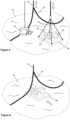
- Figure 4 shows a portion of the ground chain 20 of the mooring line 10 lying on the seabed 18. Part of the catenary curvature of the mooring line 10 between the FPSO 12 and the seabed 18 is evident on the right side of Figure 4 , where the ground chain 20 rises above the seabed 18.
- the pile 16 to which the ground chain 20 is attached is not shown but will lie to the left of the portion of the ground chain 20 shown in Figure 4 , at the end of a further portion of the ground chain 20 buried in the seabed 18.
- Figure 5 shows a mid-point of the ground chain 20 lifted from and held above the seabed 18 by a wire 34 that hangs from a surface support vessel (not shown).
- the wire 34 suitably hangs from a winch on the vessel, such as an abandonment and recovery (A&R) winch, but could instead hang from a crane on the vessel.
- A&R abandonment and recovery
- the surface support vessel has also lowered a frame 36 onto the seabed 18 in a holding location beside the raised portion of the ground chain 20.
- the frame 36 carries a connection mechanism 38 that is arranged to grip or engage the ground chain 20.
- the connection mechanism 38 may, for example, employ the principle of a clamp or a chain stopper as disclosed in CN 104802934 .
- the frame 36 also carries one or more guide tubes 40 to receive pin piles, as will be described more fully with reference to Figure 8 of the drawings.
- the frame 36 is suitably lowered from a crane on the surface support vessel but could instead hang from a winch on the vessel.
- An ROV 42 is shown in attendance to monitor the operation and to disconnect slings 44 that support the frame 36.
- This translational, generally horizontal movement of the frame 36 could be achieved by using the crane on the surface support vessel to lift the frame 36 from the holding location on the seabed 18.
- the ROV 42 shown in Figure 5 can, if needs be, disconnect and reconnect slings 44 to avoid the slings 44 clashing with the raised portion of the ground chain 20.
- Another approach is to slide the frame 36 across the seabed 18 like a sled into its final position under the ground chain 20.
- connection mechanism 38 defines an upwardly-opening receptacle for this purpose.
- the connection mechanism 38 embraces and receives the ground chain 20.
- pin piles 46 are inserted into the guide tubes 40 on the frame 36 to secure the frame 36 to the seabed 18. This completes the supplementary foundation 32 as also shown in Figure 3 .
- connection mechanism 38 is operable remotely to connect the ground chain 20 to the supplementary foundation 32.
- the connection mechanism 38 clamps the ground chain 20 or engages links of the ground chain 20 in the manner of a chain stopper.
- the FPSO 12 remains moored thereafter using the pile foundation 16 and the supplementary foundation 32 in combination to resist tension in the mooring line 10 without disconnecting the line 10 from either foundation 16, 32.
- the line 10 remains connected to both foundations 16, 32 thereafter and may remain so connected at least until the whole mooring system is eventually decommissioned. This may therefore be for longer than a moored FPSO 12 or other surface installation remains on station, which could be for more than twenty years.
- FIG. 9 shows a supplementary foundation 48 in a second embodiment of the invention, being a variant of the first embodiment shown in Figures 3 to 8 .
- a frame 36 supports a connection mechanism 38 as before but the guide tubes 40 are omitted.
- the frame 36 is anchored by remote foundation elements that are exemplified here as piles 50 but could take other forms such as drag anchors.
- the frame 36 is connected to the piles 50 by respective tensile links 52, which could be of chain or wire.
- the ground chain 20 is placed between laterally-spaced foundation elements such as the piles 50. This balances forces on the system while leaving space for installing the piles 50 without having to divert the ground chain 20 laterally as shown in the next embodiments.
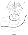
- FIGS 10 and 11 show a supplementary foundation 54 in a third embodiment of the invention, in which a connection mechanism 38 is integrated with a foundation member.
- the foundation member is exemplified here as a suction pile 56.
- the top of the pile 56 is equivalent to the frame 36 of the preceding embodiments.
- Figure 10 shows the ground chain 20 pulled laterally across the seabed 18 to allow space for installation of the pile 56 along the normal route of the ground chain 20. Once the pile 56 has been installed in the seabed 18, the ground chain 20 is lifted into engagement with the connection mechanism 38 as shown in Figure 11 .
- Figure 12 shows a supplementary foundation 58 in a fourth embodiment of the invention, in which a frame 36 that supports a connection mechanism 38 can be mounted to a pre-installed pile 60 via an interface structure 62.
- the ground chain 20 extending across the seabed 18 is shown here diverted to allow space for installation of the pile 60 along the normal route of the ground chain 20.
- connection mechanism 38 is lifted into engagement with the connection mechanism 38 in a similar way to the arrangement shown in Figure 11 .
Landscapes
- Engineering & Computer Science (AREA)
- Chemical & Material Sciences (AREA)
- Combustion & Propulsion (AREA)
- Mechanical Engineering (AREA)
- Ocean & Marine Engineering (AREA)
- General Life Sciences & Earth Sciences (AREA)
- Life Sciences & Earth Sciences (AREA)
- Mining & Mineral Resources (AREA)
- Paleontology (AREA)
- Civil Engineering (AREA)
- General Engineering & Computer Science (AREA)
- Structural Engineering (AREA)
- Foundations (AREA)
- Artificial Fish Reefs (AREA)
Claims (22)
- Procédé d'augmentation de la capacité d'un système d'ancrage qui comprend une fondation sous-marine préexistante (16) à un premier emplacement du fond marin et une ligne d'ancrage (10) raccordée à la fondation sous-marine préexistante (16) et s'étendant jusqu'à une unité flottante ancrée (12), le procédé comprenant :installer une fondation sous-marine supplémentaire (32 ; 48 ; 54 ; 58) à un second emplacement du fond marin ; etraccorder la ligne d'ancrage (10) à la fondation sous-marine supplémentaire (32 ; 48 ; 54 ; 58) tout en maintenant le raccordement entre la ligne d'ancrage (10) et la fondation sous-marine préexistante (16).
- Procédé selon la revendication 1, comprenant le fait de déplacer une partie de la ligne d'ancrage (10) au niveau du second emplacement du fond marin afin de faire de la place pour l'installation d'au moins une partie de la fondation sous-marine supplémentaire (32 ; 48 ; 54 ; 58).
- Procédé selon la revendication 2, comprenant le fait d'élever la partie déplacée de la ligne d'ancrage (10) de façon à l'éloigner du fond marin (18).
- Procédé selon la revendication 3, comprenant le fait de déplacer au moins une partie de la fondation sous-marine supplémentaire (32 ; 48 ; 54 ; 58) jusqu'à une position située sous la partie déplacée de la ligne d'ancrage (10).
- Procédé selon la revendication 4, précédé par l'abaissement d'au moins une partie de la fondation sous-marine supplémentaire (32 ; 48 ; 54 ; 58) jusqu'à un emplacement du fond marin à côté de la ligne d'ancrage (10).
- Procédé selon la revendication 2, comprenant le fait de dévier la partie déplacée de la ligne d'ancrage (10) de façon à contourner le second emplacement du fond marin et le fait de poser cette partie déplacée de la ligne d'ancrage (10) sur le fond marin (18).
- Procédé selon l'une quelconque des revendications 2 à 6, comprenant le fait de déplacer la partie déplacée de la ligne d'ancrage (10) de façon à la raccorder à au moins une partie de la fondation sous-marine supplémentaire (32 ; 48 ; 54 ; 58).
- Procédé selon l'une quelconque des revendications précédentes, comprenant le fait de placer un châssis (36) de la fondation sous-marine supplémentaire (32 ; 48 ; 54 ; 58) sur le fond marin (18), le fait d'implanter un ou plusieurs éléments de fondation (46 ; 50 ; 56 ; 60) dans le fond marin (18), le fait d'accoupler l'élément ou chaque élément de fondation (46 ; 50 ; 56 ; 60) au châssis (36) et le fait de raccorder la ligne d'ancrage (10) au châssis (36).
- Procédé selon la revendication 8, comprenant le fait d'accoupler l'élément ou chaque élément de fondation (46) au châssis (36) en installant l'élément ou chaque élément de fondation (46) dans ou à travers une structure de guidage (40) incluse dans le châssis (36) ou attachée à celui-ci.
- Procédé selon la revendication 8, comprenant le fait de placer un lien (52) entre le châssis (36) et l'élément ou chaque élément de fondation (50), ledit élément de fondation (50) étant implanté dans le fond marin (18) et espacé du châssis (36).
- Procédé selon la revendication 1, comprenant le fait d'accoupler un châssis (36) de la fondation sous-marine supplémentaire (58) à un élément de fondation (60) de la fondation sous-marine supplémentaire (58) préinstallé au niveau du second emplacement du fond marin.
- Procédé selon la revendication 11, comprenant le fait d'abaisser le châssis (36) sur l'élément de fondation (60).
- Procédé selon la revendication 1, dans lequel la fondation sous-marine supplémentaire (32 ; 48 ; 54 ; 58) est un pieu, le procédé comprenant le fait de raccorder la ligne d'ancrage (10) au pieu par le biais d'un mécanisme de raccordement (38) intégré au pieu.
- Procédé selon l'une quelconque des revendications précédentes, comprenant le fait de continuer d'ancrer l'unité flottante (12) au moyen de la fondation sous-marine existante (16) et de la fondation sous-marine supplémentaire (32 ; 48 ; 54 ; 58) en combinaison pour assurer une résistance à la tension dans la ligne d'ancrage (10) sans détacher la ligne (10) de l'une ou l'autre des fondations (16, 32 ; 48 ; 54 ; 58).
- Procédé selon l'une quelconque des revendications précédentes, dans lequel le second emplacement du fond marin est espacé du premier emplacement du fond marin sur le fond marin (18).
- Procédé selon l'une quelconque des revendications précédentes, dans lequel une section de chaîne (20) de la ligne d'ancrage (10) est raccordée à la fondation sous-marine supplémentaire (32 ; 48 ; 54 ; 58) par la fixation par serrage de la section de chaîne (20) ou par la mise en prise mécanique de maillons de la section de chaîne (20).
- Procédé selon l'une quelconque des revendications précédentes, dans lequel la ligne d'ancrage (10) est raccordée à la fondation sous-marine supplémentaire (32 ; 48 ; 54 ; 58) en entourant la ligne d'ancrage (10).
- Système d'ancrage, comprenant :une première fondation sous-marine (16) à un premier emplacement du fond marin ;une ligne d'ancrage (10) raccordée à la première fondation sous-marine (16) et s'étendant jusqu'à une unité flottante ancrée (12) ; etune fondation sous-marine supplémentaire (32 ; 48 ; 54 ; 58) à un second emplacement du fond marin, raccordée à la ligne d'ancrage (10) par un dispositif de raccordement mécanique (38) manœuvrable à distance qui définit un réceptacle ouvert vers le haut destiné à recevoir la ligne d'ancrage (10).
- Système d'ancrage selon la revendication 18, dans lequel le dispositif de raccordement mécanique (38) raccorde la fondation sous-marine supplémentaire (32 ; 48 ; 54 ; 58) à une section de chaîne (20) de la ligne d'ancrage (10) par la fixation par serrage de la section de chaîne (20) ou par la mise en prise de maillons de la section de chaîne (20).
- Système d'ancrage selon la revendication 18 ou la revendication 19, dans lequel la fondation sous-marine supplémentaire (32 ; 48 ; 54 ; 58) comprend :un châssis (36) supportant le dispositif de raccordement (38) ; etun ou plusieurs éléments de fondation (46 ; 50 ; 56 ; 60) implantés dans le fond marin (18) et accouplés au châssis (36).
- Système d'ancrage selon l'une quelconque des revendications 18 à 20, comprenant une interface (62) au sommet d'au moins un élément de fondation (60) et/ou sous le châssis (36) pour l'accouplement du châssis (36) à l'élément de fondation (60).
- Système d'ancrage selon la revendication 18 ou la revendication 19, dans lequel la fondation sous-marine supplémentaire (32 ; 48 ; 54 ; 58) est un pieu et le dispositif de raccordement (38) est intégré au pieu.
Applications Claiming Priority (2)
| Application Number | Priority Date | Filing Date | Title |
|---|---|---|---|
| GB1610516.5A GB2551379B (en) | 2016-06-16 | 2016-06-16 | Upgrading subsea foundations of mooring systems |
| PCT/IB2017/000933 WO2017216638A1 (fr) | 2016-06-16 | 2017-06-15 | Amélioration de fondations sous-marines de systèmes d'amarrage |
Publications (2)
| Publication Number | Publication Date |
|---|---|
| EP3472036A1 EP3472036A1 (fr) | 2019-04-24 |
| EP3472036B1 true EP3472036B1 (fr) | 2025-04-02 |
Family
ID=56894968
Family Applications (1)
| Application Number | Title | Priority Date | Filing Date |
|---|---|---|---|
| EP17754783.3A Active EP3472036B1 (fr) | 2016-06-16 | 2017-06-15 | Amélioration de fondations sous-marines de systèmes d'amarrage |
Country Status (5)
| Country | Link |
|---|---|
| US (1) | US10760241B2 (fr) |
| EP (1) | EP3472036B1 (fr) |
| AU (1) | AU2017283742B2 (fr) |
| GB (1) | GB2551379B (fr) |
| WO (1) | WO2017216638A1 (fr) |
Families Citing this family (9)
| Publication number | Priority date | Publication date | Assignee | Title |
|---|---|---|---|---|
| ES2956037T3 (es) * | 2018-03-02 | 2023-12-12 | Vicinay Mooring Connectors S A | Tensor de una línea de fondeo de una estructura flotante |
| US10870965B2 (en) | 2018-08-30 | 2020-12-22 | Exxonmobil Upstream Research Company | Mat incorporated pile anchor reinforcement systems |
| WO2020046615A1 (fr) * | 2018-08-30 | 2020-03-05 | Exxonmobil Upstream Research Company | Systèmes intégrés de renforcement d'ancrage de piles |
| AU2020380170A1 (en) * | 2019-11-07 | 2022-04-21 | Trendsetter Vulcan Offshore, Inc. | Systems and methods for tethering a subsea structure |
| CN111089804B (zh) * | 2020-01-20 | 2022-04-26 | 福建工程学院 | 一种危桥爆破拆除对地下结构剪切破坏的安全性预测方法 |
| KR102266943B1 (ko) * | 2021-04-19 | 2021-06-18 | 김승진 | 부이 앵커 및 상기 부이 앵커가 구비된 정박장치 |
| EP4101806B1 (fr) * | 2021-06-07 | 2025-03-19 | Vinci Construction Grands Projets | Equipement sous-marin pour la mise en tension de lignes d'ancrage d'une structure offshore et procédé d'installation d'un tel équipement |
| CN114194333A (zh) * | 2022-02-07 | 2022-03-18 | 中国华能集团清洁能源技术研究院有限公司 | 浮式平台系泊系统和安装方法、海上风电系统和安装方法 |
| NO349061B1 (en) * | 2023-10-02 | 2025-09-08 | Subsea 7 Norway As | Subsea foundations |
Citations (4)
| Publication number | Priority date | Publication date | Assignee | Title |
|---|---|---|---|---|
| US4090462A (en) * | 1977-05-10 | 1978-05-23 | Bossert Manufacturing Corporation | Dual anchor apparatus and method of using same |
| WO2002062653A1 (fr) * | 2001-02-07 | 2002-08-15 | Stolt Offshore Sa | Procedes et appareil destines a l'amarrage et au raccordement de cables aux articles au fond marin |
| WO2011047736A1 (fr) * | 2009-10-23 | 2011-04-28 | Bluewater Energy Services B.V. | Procédé pour décrocher une bouée d'un navire et dispositif destiné à être utilisé avec ce procédé |
| WO2017105663A1 (fr) * | 2015-12-18 | 2017-06-22 | Barber Gerald L | Éolienne avec caractéristiques de sécurité améliorées |
Family Cites Families (14)
| Publication number | Priority date | Publication date | Assignee | Title |
|---|---|---|---|---|
| DE930199C (de) | 1952-05-30 | 1955-07-11 | Paul Nebel | Vorrichtung zum Auflockern des Schleudergutes innerhalb einer Schubzentrifuge |
| US3712260A (en) * | 1969-11-14 | 1973-01-23 | Texaco Inc | Marine terminal mooring |
| US5061131A (en) | 1990-03-05 | 1991-10-29 | Odeco, Inc. | Structure and method for restraining motion of a marine structure |
| DE9301099U1 (de) * | 1993-01-27 | 1993-05-19 | Bouchier, France | Ankerhilfe |
| US5390618A (en) * | 1993-05-17 | 1995-02-21 | Reading & Bates Development Co. | Offshore mooring system |
| US6009825A (en) * | 1997-10-09 | 2000-01-04 | Aker Marine, Inc. | Recoverable system for mooring mobile offshore drilling units |
| US6719496B1 (en) * | 1997-11-01 | 2004-04-13 | Shell Oil Company | ROV installed suction piles |
| US20070017429A1 (en) * | 2005-07-21 | 2007-01-25 | Riggs John M | Reverse tensioned mooring system |
| GB0707673D0 (en) | 2007-04-20 | 2007-05-30 | Acergy Norway As | Methods of and apparatus for mooring and for connecting lines to articles on the seabed |
| US20090123235A1 (en) * | 2007-11-08 | 2009-05-14 | Technip France | Outer pipe sleeve for a sea floor mooring pile |
| US7976246B1 (en) * | 2009-01-22 | 2011-07-12 | Kahn Offshore B.V. | System for deploying a deepwater mooring spread |
| NO2765895T3 (fr) * | 2014-02-06 | 2018-08-04 | ||
| US9487272B2 (en) * | 2014-03-14 | 2016-11-08 | Intermoor, Inc. | Systems and methods for tensioning mooring lines at the seafloor |
| CN104802934B (zh) | 2015-04-01 | 2017-01-04 | 中国海洋石油总公司 | 锚链止链结构 |
-
2016
- 2016-06-16 GB GB1610516.5A patent/GB2551379B/en active Active
-
2017
- 2017-06-15 AU AU2017283742A patent/AU2017283742B2/en active Active
- 2017-06-15 EP EP17754783.3A patent/EP3472036B1/fr active Active
- 2017-06-15 WO PCT/IB2017/000933 patent/WO2017216638A1/fr not_active Ceased
- 2017-06-15 US US16/310,405 patent/US10760241B2/en active Active
Patent Citations (4)
| Publication number | Priority date | Publication date | Assignee | Title |
|---|---|---|---|---|
| US4090462A (en) * | 1977-05-10 | 1978-05-23 | Bossert Manufacturing Corporation | Dual anchor apparatus and method of using same |
| WO2002062653A1 (fr) * | 2001-02-07 | 2002-08-15 | Stolt Offshore Sa | Procedes et appareil destines a l'amarrage et au raccordement de cables aux articles au fond marin |
| WO2011047736A1 (fr) * | 2009-10-23 | 2011-04-28 | Bluewater Energy Services B.V. | Procédé pour décrocher une bouée d'un navire et dispositif destiné à être utilisé avec ce procédé |
| WO2017105663A1 (fr) * | 2015-12-18 | 2017-06-22 | Barber Gerald L | Éolienne avec caractéristiques de sécurité améliorées |
Also Published As
| Publication number | Publication date |
|---|---|
| GB201610516D0 (en) | 2016-08-03 |
| BR112018071718A2 (pt) | 2019-02-19 |
| AU2017283742A1 (en) | 2018-11-22 |
| AU2017283742B2 (en) | 2022-12-08 |
| US20190352878A1 (en) | 2019-11-21 |
| GB2551379A (en) | 2017-12-20 |
| GB2551379B (en) | 2018-12-12 |
| US10760241B2 (en) | 2020-09-01 |
| WO2017216638A1 (fr) | 2017-12-21 |
| EP3472036A1 (fr) | 2019-04-24 |
Similar Documents
| Publication | Publication Date | Title |
|---|---|---|
| EP3472036B1 (fr) | Amélioration de fondations sous-marines de systèmes d'amarrage | |
| US8123437B2 (en) | Pipeline assembly comprising an anchoring device | |
| US20060127187A1 (en) | Anchor installation system | |
| US6910831B2 (en) | Method for installing a pile anchor | |
| KR20130124457A (ko) | 해저 정박 시스템 및 방법 | |
| US4417831A (en) | Mooring and supporting apparatus and methods for a guyed marine structure | |
| AU2018388843B2 (en) | Interconnection of subsea pipelines and structures | |
| US9140384B2 (en) | Subsea connecting apparatus and method | |
| US12252858B2 (en) | Seabed foundations | |
| WO2011099869A2 (fr) | Procédé d'installation d'un élément allongé flexible | |
| US6851895B2 (en) | Methods of and apparatus for mooring and for connecting lines to articles on the seabed | |
| EP2148807B1 (fr) | Procedes et appareils pour ancrer et pour relier des lignes a des articles sur le fond marin | |
| WO1997029949A1 (fr) | Plate-forme a cables tendus munie de cables flexibles et procede d'installation | |
| EP2704945B1 (fr) | Système d'extraction de pétrole en mer | |
| GB2562977B (en) | Upgrading subsea foundations of mooring systems | |
| EP2440708B1 (fr) | Fondation pour une tour off-shore | |
| EP3906376B1 (fr) | Méthode de liaison sous-marine de sections de conduite et outil à cet effet | |
| US20080089745A1 (en) | Method And Device For Connecting A Riser To A Target Structure | |
| US20070022934A1 (en) | Shallow water mooring system using synthetic mooring lines | |
| EP2162593B1 (fr) | Procédés de pose sous-marine d'articles allongés | |
| BR112018071718B1 (pt) | Método de melhoramento da capacidade de um sistema de amarração e sistema de amarração | |
| MXPA06013864A (es) | Metodo para desplegar una plataforma flotante |
Legal Events
| Date | Code | Title | Description |
|---|---|---|---|
| STAA | Information on the status of an ep patent application or granted ep patent |
Free format text: STATUS: UNKNOWN |
|
| STAA | Information on the status of an ep patent application or granted ep patent |
Free format text: STATUS: THE INTERNATIONAL PUBLICATION HAS BEEN MADE |
|
| PUAI | Public reference made under article 153(3) epc to a published international application that has entered the european phase |
Free format text: ORIGINAL CODE: 0009012 |
|
| STAA | Information on the status of an ep patent application or granted ep patent |
Free format text: STATUS: REQUEST FOR EXAMINATION WAS MADE |
|
| 17P | Request for examination filed |
Effective date: 20190115 |
|
| AK | Designated contracting states |
Kind code of ref document: A1 Designated state(s): AL AT BE BG CH CY CZ DE DK EE ES FI FR GB GR HR HU IE IS IT LI LT LU LV MC MK MT NL NO PL PT RO RS SE SI SK SM TR |
|
| AX | Request for extension of the european patent |
Extension state: BA ME |
|
| DAV | Request for validation of the european patent (deleted) | ||
| DAX | Request for extension of the european patent (deleted) | ||
| STAA | Information on the status of an ep patent application or granted ep patent |
Free format text: STATUS: EXAMINATION IS IN PROGRESS |
|
| 17Q | First examination report despatched |
Effective date: 20200911 |
|
| P01 | Opt-out of the competence of the unified patent court (upc) registered |
Free format text: CASE NUMBER: APP_46599/2024 Effective date: 20240812 |
|
| GRAP | Despatch of communication of intention to grant a patent |
Free format text: ORIGINAL CODE: EPIDOSNIGR1 |
|
| STAA | Information on the status of an ep patent application or granted ep patent |
Free format text: STATUS: GRANT OF PATENT IS INTENDED |
|
| RIC1 | Information provided on ipc code assigned before grant |
Ipc: B63B 21/26 20060101ALI20240927BHEP Ipc: B63B 21/50 20060101AFI20240927BHEP |
|
| INTG | Intention to grant announced |
Effective date: 20241029 |
|
| GRAS | Grant fee paid |
Free format text: ORIGINAL CODE: EPIDOSNIGR3 |
|
| GRAA | (expected) grant |
Free format text: ORIGINAL CODE: 0009210 |
|
| STAA | Information on the status of an ep patent application or granted ep patent |
Free format text: STATUS: THE PATENT HAS BEEN GRANTED |
|
| AK | Designated contracting states |
Kind code of ref document: B1 Designated state(s): AL AT BE BG CH CY CZ DE DK EE ES FI FR GB GR HR HU IE IS IT LI LT LU LV MC MK MT NL NO PL PT RO RS SE SI SK SM TR |
|
| REG | Reference to a national code |
Ref country code: GB Ref legal event code: FG4D |
|
| REG | Reference to a national code |
Ref country code: CH Ref legal event code: EP |
|
| REG | Reference to a national code |
Ref country code: DE Ref legal event code: R096 Ref document number: 602017088690 Country of ref document: DE |
|
| REG | Reference to a national code |
Ref country code: IE Ref legal event code: FG4D |
|
| PGFP | Annual fee paid to national office [announced via postgrant information from national office to epo] |
Ref country code: NO Payment date: 20250624 Year of fee payment: 9 |
|
| PGFP | Annual fee paid to national office [announced via postgrant information from national office to epo] |
Ref country code: FR Payment date: 20250626 Year of fee payment: 9 |
|
| REG | Reference to a national code |
Ref country code: NL Ref legal event code: MP Effective date: 20250402 |
|
| PG25 | Lapsed in a contracting state [announced via postgrant information from national office to epo] |
Ref country code: NL Free format text: LAPSE BECAUSE OF FAILURE TO SUBMIT A TRANSLATION OF THE DESCRIPTION OR TO PAY THE FEE WITHIN THE PRESCRIBED TIME-LIMIT Effective date: 20250402 |
|
| REG | Reference to a national code |
Ref country code: AT Ref legal event code: MK05 Ref document number: 1781072 Country of ref document: AT Kind code of ref document: T Effective date: 20250402 |
|
| PG25 | Lapsed in a contracting state [announced via postgrant information from national office to epo] |
Ref country code: PT Free format text: LAPSE BECAUSE OF FAILURE TO SUBMIT A TRANSLATION OF THE DESCRIPTION OR TO PAY THE FEE WITHIN THE PRESCRIBED TIME-LIMIT Effective date: 20250804 Ref country code: ES Free format text: LAPSE BECAUSE OF FAILURE TO SUBMIT A TRANSLATION OF THE DESCRIPTION OR TO PAY THE FEE WITHIN THE PRESCRIBED TIME-LIMIT Effective date: 20250402 Ref country code: FI Free format text: LAPSE BECAUSE OF FAILURE TO SUBMIT A TRANSLATION OF THE DESCRIPTION OR TO PAY THE FEE WITHIN THE PRESCRIBED TIME-LIMIT Effective date: 20250402 |
|
| REG | Reference to a national code |
Ref country code: LT Ref legal event code: MG9D |
|
| PG25 | Lapsed in a contracting state [announced via postgrant information from national office to epo] |
Ref country code: GR Free format text: LAPSE BECAUSE OF FAILURE TO SUBMIT A TRANSLATION OF THE DESCRIPTION OR TO PAY THE FEE WITHIN THE PRESCRIBED TIME-LIMIT Effective date: 20250703 |
|
| PG25 | Lapsed in a contracting state [announced via postgrant information from national office to epo] |
Ref country code: PL Free format text: LAPSE BECAUSE OF FAILURE TO SUBMIT A TRANSLATION OF THE DESCRIPTION OR TO PAY THE FEE WITHIN THE PRESCRIBED TIME-LIMIT Effective date: 20250402 |
|
| PGFP | Annual fee paid to national office [announced via postgrant information from national office to epo] |
Ref country code: IT Payment date: 20250731 Year of fee payment: 9 |
|
| PG25 | Lapsed in a contracting state [announced via postgrant information from national office to epo] |
Ref country code: BG Free format text: LAPSE BECAUSE OF FAILURE TO SUBMIT A TRANSLATION OF THE DESCRIPTION OR TO PAY THE FEE WITHIN THE PRESCRIBED TIME-LIMIT Effective date: 20250402 |
|
| PGFP | Annual fee paid to national office [announced via postgrant information from national office to epo] |
Ref country code: GB Payment date: 20250729 Year of fee payment: 9 |
|
| PG25 | Lapsed in a contracting state [announced via postgrant information from national office to epo] |
Ref country code: HR Free format text: LAPSE BECAUSE OF FAILURE TO SUBMIT A TRANSLATION OF THE DESCRIPTION OR TO PAY THE FEE WITHIN THE PRESCRIBED TIME-LIMIT Effective date: 20250402 |
|
| PG25 | Lapsed in a contracting state [announced via postgrant information from national office to epo] |
Ref country code: AT Free format text: LAPSE BECAUSE OF FAILURE TO SUBMIT A TRANSLATION OF THE DESCRIPTION OR TO PAY THE FEE WITHIN THE PRESCRIBED TIME-LIMIT Effective date: 20250402 |
|
| PG25 | Lapsed in a contracting state [announced via postgrant information from national office to epo] |
Ref country code: RS Free format text: LAPSE BECAUSE OF FAILURE TO SUBMIT A TRANSLATION OF THE DESCRIPTION OR TO PAY THE FEE WITHIN THE PRESCRIBED TIME-LIMIT Effective date: 20250702 |
|
| PG25 | Lapsed in a contracting state [announced via postgrant information from national office to epo] |
Ref country code: IS Free format text: LAPSE BECAUSE OF FAILURE TO SUBMIT A TRANSLATION OF THE DESCRIPTION OR TO PAY THE FEE WITHIN THE PRESCRIBED TIME-LIMIT Effective date: 20250802 |
|
| PG25 | Lapsed in a contracting state [announced via postgrant information from national office to epo] |
Ref country code: LV Free format text: LAPSE BECAUSE OF FAILURE TO SUBMIT A TRANSLATION OF THE DESCRIPTION OR TO PAY THE FEE WITHIN THE PRESCRIBED TIME-LIMIT Effective date: 20250402 |
|
| REG | Reference to a national code |
Ref country code: DE Ref legal event code: R119 Ref document number: 602017088690 Country of ref document: DE |
|
| PG25 | Lapsed in a contracting state [announced via postgrant information from national office to epo] |
Ref country code: DK Free format text: LAPSE BECAUSE OF FAILURE TO SUBMIT A TRANSLATION OF THE DESCRIPTION OR TO PAY THE FEE WITHIN THE PRESCRIBED TIME-LIMIT Effective date: 20250402 Ref country code: SM Free format text: LAPSE BECAUSE OF FAILURE TO SUBMIT A TRANSLATION OF THE DESCRIPTION OR TO PAY THE FEE WITHIN THE PRESCRIBED TIME-LIMIT Effective date: 20250402 |
|
| PG25 | Lapsed in a contracting state [announced via postgrant information from national office to epo] |
Ref country code: CZ Free format text: LAPSE BECAUSE OF FAILURE TO SUBMIT A TRANSLATION OF THE DESCRIPTION OR TO PAY THE FEE WITHIN THE PRESCRIBED TIME-LIMIT Effective date: 20250402 |
|
| PG25 | Lapsed in a contracting state [announced via postgrant information from national office to epo] |
Ref country code: EE Free format text: LAPSE BECAUSE OF FAILURE TO SUBMIT A TRANSLATION OF THE DESCRIPTION OR TO PAY THE FEE WITHIN THE PRESCRIBED TIME-LIMIT Effective date: 20250402 |
|
| PG25 | Lapsed in a contracting state [announced via postgrant information from national office to epo] |
Ref country code: SK Free format text: LAPSE BECAUSE OF FAILURE TO SUBMIT A TRANSLATION OF THE DESCRIPTION OR TO PAY THE FEE WITHIN THE PRESCRIBED TIME-LIMIT Effective date: 20250402 Ref country code: RO Free format text: LAPSE BECAUSE OF FAILURE TO SUBMIT A TRANSLATION OF THE DESCRIPTION OR TO PAY THE FEE WITHIN THE PRESCRIBED TIME-LIMIT Effective date: 20250402 |
|
| REG | Reference to a national code |
Ref country code: CH Ref legal event code: H13 Free format text: ST27 STATUS EVENT CODE: U-0-0-H10-H13 (AS PROVIDED BY THE NATIONAL OFFICE) Effective date: 20260127 |
|
| PG25 | Lapsed in a contracting state [announced via postgrant information from national office to epo] |
Ref country code: MC Free format text: LAPSE BECAUSE OF FAILURE TO SUBMIT A TRANSLATION OF THE DESCRIPTION OR TO PAY THE FEE WITHIN THE PRESCRIBED TIME-LIMIT Effective date: 20250402 |
|
| PLBE | No opposition filed within time limit |
Free format text: ORIGINAL CODE: 0009261 |
|
| STAA | Information on the status of an ep patent application or granted ep patent |
Free format text: STATUS: NO OPPOSITION FILED WITHIN TIME LIMIT |
|
| REG | Reference to a national code |
Ref country code: CH Ref legal event code: L10 Free format text: ST27 STATUS EVENT CODE: U-0-0-L10-L00 (AS PROVIDED BY THE NATIONAL OFFICE) Effective date: 20260211 |
|
| PG25 | Lapsed in a contracting state [announced via postgrant information from national office to epo] |
Ref country code: LU Free format text: LAPSE BECAUSE OF NON-PAYMENT OF DUE FEES Effective date: 20250615 |
|
| REG | Reference to a national code |
Ref country code: BE Ref legal event code: MM Effective date: 20250630 |
|
| 26N | No opposition filed |
Effective date: 20260105 |
|
| PG25 | Lapsed in a contracting state [announced via postgrant information from national office to epo] |
Ref country code: IE Free format text: LAPSE BECAUSE OF NON-PAYMENT OF DUE FEES Effective date: 20250615 Ref country code: DE Free format text: LAPSE BECAUSE OF NON-PAYMENT OF DUE FEES Effective date: 20260101 |
|
| PG25 | Lapsed in a contracting state [announced via postgrant information from national office to epo] |
Ref country code: BE Free format text: LAPSE BECAUSE OF NON-PAYMENT OF DUE FEES Effective date: 20250630 |