EP3472459B1 - Procédé de surveillance d'un réglage de pales de rotor - Google Patents
Procédé de surveillance d'un réglage de pales de rotor Download PDFInfo
- Publication number
- EP3472459B1 EP3472459B1 EP17710866.9A EP17710866A EP3472459B1 EP 3472459 B1 EP3472459 B1 EP 3472459B1 EP 17710866 A EP17710866 A EP 17710866A EP 3472459 B1 EP3472459 B1 EP 3472459B1
- Authority
- EP
- European Patent Office
- Prior art keywords
- toothed belt
- rotor blade
- monitoring
- control unit
- drive
- Prior art date
- Legal status (The legal status is an assumption and is not a legal conclusion. Google has not performed a legal analysis and makes no representation as to the accuracy of the status listed.)
- Active
Links
Images
Classifications
-
- F—MECHANICAL ENGINEERING; LIGHTING; HEATING; WEAPONS; BLASTING
- F03—MACHINES OR ENGINES FOR LIQUIDS; WIND, SPRING, OR WEIGHT MOTORS; PRODUCING MECHANICAL POWER OR A REACTIVE PROPULSIVE THRUST, NOT OTHERWISE PROVIDED FOR
- F03D—WIND MOTORS
- F03D17/00—Monitoring or testing of wind motors, e.g. diagnostics
-
- F—MECHANICAL ENGINEERING; LIGHTING; HEATING; WEAPONS; BLASTING
- F05—INDEXING SCHEMES RELATING TO ENGINES OR PUMPS IN VARIOUS SUBCLASSES OF CLASSES F01-F04
- F05B—INDEXING SCHEME RELATING TO WIND, SPRING, WEIGHT, INERTIA OR LIKE MOTORS, TO MACHINES OR ENGINES FOR LIQUIDS COVERED BY SUBCLASSES F03B, F03D AND F03G
- F05B2260/00—Function
- F05B2260/50—Kinematic linkage, i.e. transmission of position
- F05B2260/504—Kinematic linkage, i.e. transmission of position using flat or V-belts and pulleys
-
- F—MECHANICAL ENGINEERING; LIGHTING; HEATING; WEAPONS; BLASTING
- F05—INDEXING SCHEMES RELATING TO ENGINES OR PUMPS IN VARIOUS SUBCLASSES OF CLASSES F01-F04
- F05B—INDEXING SCHEME RELATING TO WIND, SPRING, WEIGHT, INERTIA OR LIKE MOTORS, TO MACHINES OR ENGINES FOR LIQUIDS COVERED BY SUBCLASSES F03B, F03D AND F03G
- F05B2260/00—Function
- F05B2260/70—Adjusting of angle of incidence or attack of rotating blades
- F05B2260/79—Bearing, support or actuation arrangements therefor
-
- F—MECHANICAL ENGINEERING; LIGHTING; HEATING; WEAPONS; BLASTING
- F05—INDEXING SCHEMES RELATING TO ENGINES OR PUMPS IN VARIOUS SUBCLASSES OF CLASSES F01-F04
- F05B—INDEXING SCHEME RELATING TO WIND, SPRING, WEIGHT, INERTIA OR LIKE MOTORS, TO MACHINES OR ENGINES FOR LIQUIDS COVERED BY SUBCLASSES F03B, F03D AND F03G
- F05B2270/00—Control
- F05B2270/80—Devices generating input signals, e.g. transducers, sensors, cameras or strain gauges
- F05B2270/804—Optical devices
- F05B2270/8041—Cameras
-
- Y—GENERAL TAGGING OF NEW TECHNOLOGICAL DEVELOPMENTS; GENERAL TAGGING OF CROSS-SECTIONAL TECHNOLOGIES SPANNING OVER SEVERAL SECTIONS OF THE IPC; TECHNICAL SUBJECTS COVERED BY FORMER USPC CROSS-REFERENCE ART COLLECTIONS [XRACs] AND DIGESTS
- Y02—TECHNOLOGIES OR APPLICATIONS FOR MITIGATION OR ADAPTATION AGAINST CLIMATE CHANGE
- Y02E—REDUCTION OF GREENHOUSE GAS [GHG] EMISSIONS, RELATED TO ENERGY GENERATION, TRANSMISSION OR DISTRIBUTION
- Y02E10/00—Energy generation through renewable energy sources
- Y02E10/70—Wind energy
- Y02E10/72—Wind turbines with rotation axis in wind direction
Definitions
- the invention relates to a method for monitoring a rotor blade adjustment in a wind power plant, in which the adjustment of a rotatably mounted rotor blade is carried out by a toothed belt drive, in which a toothed belt provided with reinforcement cords is at least partially in a drive pulley connected to a drive motor and provided with complementary teeth engages all around and is connected at the foot of the rotor blade to the latter to transmit the torque required for the adjustment in a positive and / or frictional manner.
- the invention also relates to a device which is particularly suitable for carrying out the method.
- the generation of electrical energy by wind power plants is particularly effective when the wind power plant or the generator can work in the range of its nominal power. At different wind speeds, this is efficient and gentle on the material for the entire system if the speed of the rotor is kept almost constant despite fluctuating wind speeds.
- the exact power control is therefore particularly important for the smooth running of the generator. Power consumption is usually regulated by turning the rotor blades. The rotor blades are brought into different positions in relation to the inflow by the wind by means of a blade adjustment drive, the so-called rotor blade adjustment.
- the rotor blades When the wind is weak, the rotor blades are adjusted so that the rotor blade profile is against the flow with a large angle of attack, ie with almost full width. When the wind is refreshing, the angle of attack is then increasingly reduced until a storm the blades are directed parallel to the wind flow and in extreme cases the rotor stops and stops rotating.
- the rotor blade adjustment is therefore one of the most important control systems in a modern wind turbine.
- the regulation of the adjustment is also referred to as "pitch regulation”.
- blade adjustment by up to 180 degrees around the longitudinal axis of the rotor, which is perpendicular to the axis of rotation, is possible.
- a toothed belt meshes over a drive pulley connected to a drive motor, which is usually attached to the motor shaft, and further over a toothed ring attached to the foot of the rotor blade. Because of the radial force acting on the toothed ring circumference via the toothed belt, the rotor blade can then be rotated in any desired manner.
- a drive pulley connected to a drive motor, which is usually attached to the motor shaft, and further over a toothed ring attached to the foot of the rotor blade. Because of the radial force acting on the toothed ring circumference via the toothed belt, the rotor blade can then be rotated in any desired manner.
- Such a device discloses the DE 10 2013 206 878 A1 .
- remote diagnosis systems are now in use, in which the wind turbines are connected to a remote diagnosis network, which transmits all values and operating states and any faults to a control center. This then coordinates all maintenance work. Many mechanical and electrical / electronic components of a wind turbine are monitored in order to detect changes and prevent damage events by taking timely measures. Disadvantageously, monitoring the state of rotor blade adjustments, in particular rotor blade adjustments with toothed belt drives, has not hitherto been included.
- the object of the invention was therefore to provide a method and a device for monitoring toothed belt drives for rotor blade adjustment in wind power plants, which can be integrated into the monitoring of the wind power plant as part of a remote diagnosis.
- sensors or test devices and / or video or recording devices determine or recorded data, in particular measurement data, which represent the operating state or physical-geometric state of the toothed belt adjusting the rotor blades within the rotor blade adjustment, are reported by means of a radio transmission device to a monitoring center remote from the wind power plant and evaluated there.
- Such measurement data which represent the operating state or the physical-geometric state of the toothed belt adjusting the rotor blades within the rotor blade adjustment, allow the state of the adjusted mechanism to be assessed without a technician having to climb onto the wind turbine.
- Typical of the operating condition would be the fabric condition of a fabric-coated belt, which can be checked by video surveillance. If damaged tissue, torn threads or tissue tears are found during such monitoring, intervention in the sense of maintenance is necessary.
- the physical-geometric condition of a toothed belt can also be monitored by a camera, which is aimed at certain points on the belt and there e.g. Can discover breaks or cracks that indicate material fatigue.
- the toothed belt advantageously engages partially in a circumferential manner with a toothed ring provided with complementary external teeth and arranged at the foot of the rotor blade. This results in a particularly safe and play-free transmission of the torque required for the adjustment.
- An advantageous further development consists in that a control unit belonging to the toothed belt drive or to the rotor blade adjustment / adjusting device is provided, by means of which the generation, recording and requesting of measurement data as well as the transmission to the monitoring center is initiated and controlled. This allows programmed test routines run and regular checks are carried out periodically.
- a further advantageous embodiment consists in that the strength cords for magnetic field changes indicating cord breaks are checked using a magnetic testing device and / or the base of the tooth base of the teeth of the toothed belt for cracks or damage is checked with a camera. In any case, these are the two most informative tests that can be used to identify damage that can have a direct and serious impact on the adjustment.
- a further advantageous embodiment consists in that a rotation angle sensor assigned to the belt drive is provided, the signals of which are used in the control unit for the correct assignment of the data or measurement data.
- the control unit controls the toothed belt drive on a signal from the monitoring center or at periodic intervals so that all rotational positions of the rotatably mounted rotor blade travel through and the associated measurement data of the toothed belt adjusting the rotor blades are determined and stored in the (Measurement run)
- the control device coordinates the photo and video recording and the measurements of the sensors or testing devices in such a way that a clear assignment of the different measurement data to a belt position is possible.
- control unit initiates a measurement run depending on the wind situation, during which the blade adjustment continuously runs through its entire angular range and thus all belt positions for checking.
- the camera or the camera system on the back roller looks at the counter-bent toothed belt. By bending back the toothed belt, in which the teeth are spread, damage to the Tooth base and the tissue can be recognized particularly clearly.
- the camera system has one or more LED spotlights in order to achieve good illumination of the area under consideration.
- a further advantageous embodiment of the device according to the invention in this sense consists in that a toothed belt provided with magnetizable strength member cords is provided in the toothed belt drive and the device for non-destructive testing is designed as a magnetic testing device, preferably a magnetic testing device in which the strength member with a permanent magnet Magnetized cords during operation and the formation of a magnetic field thus created is checked with the aid of a number of magnetic field sensors (sensor array).
- sensor array sensor array
- the device for non-destructive testing is arranged on a free run within the toothed belt drive.
- the measurement results are hardly disturbed by other facilities.
- the magnetic test for example, it is ensured that the magnetic field of the reinforcement cords is not influenced by other metallic deflection rollers and leads to incorrect measurements.
- radio device and the receiving device exchange data bidirectionally via a mobile radio network and / or via the Internet.
- existing infrastructure for remote monitoring / remote diagnosis can be used in a simple manner.
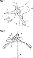
- Fig. 1 shows in principle a wind turbine 1 with a generator housing 3 attached to a tower 2.
- the wind turbine has a three-bladed rotor with the blades 4, 5 and 6, which are mounted in the hub 7 and all of which can be adjusted to the incoming wind 13, ie by their longitudinal axes 8 are rotatable and are equipped with a rotor blade adjustment.
- Fig. 2 shows a schematic diagram of the rotor blade adjustment of this wind turbine seen in the direction of the blade longitudinal axis 8.
- the rotatably mounted rotor blades are adjusted by a toothed belt drive, in which a toothed belt 9 provided with magnetizable reinforcement cords meshes with a drive pulley 10 on the one hand and, on the other hand, with a toothed ring 12 with external teeth 11 arranged at the foot of the rotor blade.
- the drive pulley 10 is driven by a drive motor, not shown here.
- the drive pulley and the toothed ring are provided with teeth complementary to the toothed belt, and the toothed belt wraps around the drive pulley and toothed ring around a part of the respective outer circumference.
- the toothed belt 9 also runs around a deflection roller 14 designed as a back roller, which also serves as a tension roller.
- the toothed belt 9, drive pulley 10, deflection roller 14 and toothed ring 12 thus form the toothed belt drive, with the aid of which the toothed ring is rotated and the rotor blade is thus rotated / adjusted about its longitudinal axis 8.
- a device for non-destructive testing is arranged within the installation space required for the toothed belt drive, namely a magnetic testing device 15, in which the reinforcement cords are magnetized during operation and with a permanent magnet the formation of a resulting magnetic field is checked with the aid of a number of magnetic field sensors, a so-called sensor array.
- the magnetic testing device 15 is arranged on a free run of the toothed belt within the toothed belt drive, here in the free run between the ring gear 12 and the drive pulley 10.
- Such a known magnetic test is particularly suitable for testing and monitoring the magnetizable reinforcement cords located in the toothed belt, since the entire magnet testing device requires little installation space and generates extremely clear signals. Even if individual cords break, the magnetic field that is linearly formed around the cords deforms into a bulbous shape around the broken ends and can thus be easily dictated.
- a camera 16 directed to its profile side with corresponding lighting devices is arranged so that it looks at the counter-bent toothed belt.
- control unit 17 for processing the signals from the magnetic test device and the camera signals
- radio device 18 communicating with the control unit 17 for transmitting the test signals and camera signals to a receiving device, which is located in a distance from the wind turbine and not shown here Monitoring center is located.
Landscapes
- Engineering & Computer Science (AREA)
- Life Sciences & Earth Sciences (AREA)
- Sustainable Development (AREA)
- Sustainable Energy (AREA)
- Chemical & Material Sciences (AREA)
- Combustion & Propulsion (AREA)
- Mechanical Engineering (AREA)
- General Engineering & Computer Science (AREA)
- Wind Motors (AREA)
Claims (10)
- Procédé de surveillance d'un positionnement de pale de rotor sur un aérogénérateur (1), avec lequel le positionnement d'une pale de rotor (4, 5, 6) montée rotative est effectué par un mécanisme à courroie crantée (9, 10, 12, 14), avec lequel une courroie crantée (9) pourvue de côtes de renfort de résistance vient en prise partiellement circonférentielle au moins dans une poulie d'entraînement (10) reliée à un moteur d'entraînement et pourvue d'une denture complémentaire et, au niveau du pied de la pale de rotor, est reliée avec ce dernier par complémentarité de formes et/ou par friction en vue de transmettre le couple nécessaire au positionnement, caractérisé en ce que des données déterminées par des capteurs ou des dispositifs de contrôle (15) et/ou des dispositifs vidéo ou d'enregistrement (16), notamment des données de mesure, qui représentent l'état opérationnel ou l'état physico-géométrique de la courroie crantée (9) qui positionne la pale de rotor au sein du positionnement de la pale de rotor, sont signalées au moyen d'un dispositif de commande et de radiotransmission (17, 18) dans une centrale de surveillance éloignée de l'aérogénérateur et y sont évaluées.
- Procédé selon la revendication 1, avec lequel la courroie crantée (9) vient en prise partiellement circonférentielle dans une couronne dentée (12) pourvue d'une denture complémentaire disposée au pied de la pale de rotor.
- Procédé selon la revendication 1 ou 2, avec lequel une unité de commande (17) associée au mécanisme à courroie crantée ou au positionnement de pale de rotor est présente, par laquelle sont initiés et commandés la génération, l'enregistrement et la demande de données de mesure ainsi que la transmission à la centrale de surveillance.
- Procédé selon l'une des revendications 1 à 3, avec lequel les côtes de renfort de résistance sont contrôlées par le biais d'un dispositif de contrôle magnétique (15) en vue de déceler la présence de variations du champ magnétique indiquant des ruptures de côte et/ou le fond de pied de dent des dents de la courroie crantée est contrôlé avec une caméra (16) en vue de déceler des fissures ou des dommages.
- Procédé selon l'une des revendications 1 à 4, avec lequel un transmetteur d'angle de rotation associé au mécanisme à courroie est présent, dont les signaux sont utilisés dans l'unité de commande (17) pour l'affectation en position correcte des données ou des données de mesure.
- Procédé selon la revendication 5, avec lequel l'unité de commande (17) commande le mécanisme à courroie crantée sur un signal de la centrale de surveillance ou à intervalles périodiques de telle sorte que toutes les positions de rotation de la pale de rotor (4, 5, 6) montée rotative sont franchies et les données de mesure associées de la courroie crantée qui positionne les pales de rotor sont déterminées et mémorisées (course de mesure) .
- Dispositif pour mettre en œuvre un procédé selon l'une des revendications 1 à 6, avec lequel la courroie crantée (9) qui vient en prise partiellement circonférentielle dans la poulie d'entraînement (10) et la couronne dentée (12) dans le mécanisme à courroie crantée circule autour d'au moins un galet de renvoi réalisé sous la forme d'un galet pousseur (14), caractérisé en ce que les dispositifs suivants sont associés au mécanisme à courroie crantée :a) un dispositif de contrôle (15) non destructif destiné à surveiller la côte de renfort de résistance qui se trouve dans la courroie crantée,b) une caméra (16) munie de dispositifs d'éclairage correspondants, orientée dans la zone de l'application de la courroie crantée (9) contre le galet pousseur sur son côté profiléc) une unité de commande (17) destinée à traiter les signaux du dispositif de contrôle (15) non destructif et les signaux de caméra,d) un dispositif radioélectrique (18) qui communique avec l'unité de commande (17) en vue de communiquer les signaux de contrôle et les signaux de caméra à un dispositif de réceptionle dispositif de réception possédant un dispositif de calcul destiné à mémoriser les signaux de contrôle et de caméra ainsi qu'à les traiter à des fins de reconnaissance de défaut / de diagnostic de la courroie crantée.
- Dispositif de surveillance selon la revendication 7, avec lequel une courroie crantée (9) pourvue de côtes de renfort de résistance magnétisables se trouve dans le mécanisme à courroie crantée et le dispositif destiné à un contrôle non destructif est réalisé sous la forme d'un dispositif de contrôle magnétique (15), de préférence un dispositif de contrôle magnétique avec lequel la côte de renfort de résistance est magnétisée pendant le fonctionnement avec un aimant permanent et la formation d'un champ magnétique ainsi produit est contrôlée à l'aide d'une pluralité de capteurs de champ magnétique (réseau de capteurs).
- Dispositif de surveillance selon la revendication 7, avec lequel le dispositif destiné à un contrôle non destructif est disposé au niveau d'un brin libre à l'intérieur du mécanisme à courroie crantée.
- Dispositif de surveillance selon l'une des revendications 7 à 9, avec lequel le dispositif radioélectrique et le dispositif de réception échangent des données bidirectionnelles par le biais d'un réseau de radiocommunication mobile et/ou par le biais de l'Internet.
Applications Claiming Priority (2)
| Application Number | Priority Date | Filing Date | Title |
|---|---|---|---|
| DE102016210755.0A DE102016210755A1 (de) | 2016-06-16 | 2016-06-16 | Verfahren zur Überwachung einer Rotorblattverstellung |
| PCT/EP2017/055891 WO2017215797A1 (fr) | 2016-06-16 | 2017-03-14 | Procédé de surveillance d'un réglage de pales de rotor |
Publications (2)
| Publication Number | Publication Date |
|---|---|
| EP3472459A1 EP3472459A1 (fr) | 2019-04-24 |
| EP3472459B1 true EP3472459B1 (fr) | 2020-06-17 |
Family
ID=58314185
Family Applications (1)
| Application Number | Title | Priority Date | Filing Date |
|---|---|---|---|
| EP17710866.9A Active EP3472459B1 (fr) | 2016-06-16 | 2017-03-14 | Procédé de surveillance d'un réglage de pales de rotor |
Country Status (5)
| Country | Link |
|---|---|
| EP (1) | EP3472459B1 (fr) |
| CN (1) | CN109312719B (fr) |
| DE (1) | DE102016210755A1 (fr) |
| DK (1) | DK3472459T3 (fr) |
| WO (1) | WO2017215797A1 (fr) |
Families Citing this family (6)
| Publication number | Priority date | Publication date | Assignee | Title |
|---|---|---|---|---|
| US11473564B2 (en) | 2018-01-18 | 2022-10-18 | General Electric Company | System and method for monitoring a wind turbine pitch bearing |
| EP4077928A1 (fr) | 2019-12-17 | 2022-10-26 | General Electric Company | Système et procédé de surveillance de la santé d'une pale de rotor d'une éolienne |
| DE102019008854B3 (de) | 2019-12-19 | 2021-02-25 | Horst Bendix | Antriebssystem für Binnenwindanlagen großer Höhen und Leistungen |
| DE102022203808A1 (de) * | 2022-04-14 | 2023-10-19 | Contitech Antriebssysteme Gmbh | Riemenbetriebene Verstelleinrichtung |
| US12607163B2 (en) | 2022-08-31 | 2026-04-21 | GE Vernova Renovables Espana, S.L.U. | System and method for detecting and responding to rotor blade damage in a wind turbine |
| EP4386198A1 (fr) * | 2022-12-14 | 2024-06-19 | Siemens Gamesa Renewable Energy A/S | Dispositif et procédé d'aide au montage ou au démontage d'une pale de rotor |
Family Cites Families (7)
| Publication number | Priority date | Publication date | Assignee | Title |
|---|---|---|---|---|
| DK1524433T3 (da) * | 2003-10-14 | 2012-04-23 | Repower Systems Ag | Omdrejningstalregulering i et vindenergianlæg med to tilnærmelsessensorer til omdrejningstalmålingen |
| EP2005136A4 (fr) * | 2006-03-29 | 2010-09-29 | Mats Lipowski | Appareil et procede de detection de l'usure d'une courroie de transmission et de surveillance des performances d'un systeme d'entrainement par courroie |
| US7745948B2 (en) * | 2007-11-28 | 2010-06-29 | General Electric Company | Emergency pitch drive unit for a wind turbine |
| DE102008013926B4 (de) * | 2008-03-12 | 2019-07-25 | Vensys Energy Ag | Vorrichtung zur Verstellung des Anstellwinkels eines Rotorblattes einer Windenergieanlage |
| GB201101646D0 (en) * | 2011-01-31 | 2011-03-16 | Romax Technology Ltd | Transfer box |
| DE102013206878A1 (de) * | 2012-04-16 | 2013-10-17 | Suzlon Energy Gmbh | Verstellvorrichtung für ein Rotorblatt einer Windturbine |
| SE537274C2 (sv) * | 2013-07-01 | 2015-03-24 | Scania Cv Ab | Förfarande och anordning för detektering av rembrott på en rem som är anordnad i ett motorfordon |
-
2016
- 2016-06-16 DE DE102016210755.0A patent/DE102016210755A1/de not_active Withdrawn
-
2017
- 2017-03-14 EP EP17710866.9A patent/EP3472459B1/fr active Active
- 2017-03-14 WO PCT/EP2017/055891 patent/WO2017215797A1/fr not_active Ceased
- 2017-03-14 DK DK17710866.9T patent/DK3472459T3/da active
- 2017-03-14 CN CN201780037235.XA patent/CN109312719B/zh active Active
Non-Patent Citations (1)
| Title |
|---|
| None * |
Also Published As
| Publication number | Publication date |
|---|---|
| DK3472459T3 (da) | 2020-08-31 |
| DE102016210755A1 (de) | 2017-12-21 |
| EP3472459A1 (fr) | 2019-04-24 |
| CN109312719A (zh) | 2019-02-05 |
| WO2017215797A1 (fr) | 2017-12-21 |
| CN109312719B (zh) | 2021-05-04 |
Similar Documents
| Publication | Publication Date | Title |
|---|---|---|
| EP3472459B1 (fr) | Procédé de surveillance d'un réglage de pales de rotor | |
| EP3343030B1 (fr) | Dispositif et procédé de surveillance d'un palier de pale d'une éolienne | |
| EP2435809B1 (fr) | Machine et procédé de surveillance de l'état d'un palier de secours d'une machine | |
| DE102006054667B4 (de) | Kollisionswarnsystem für eine Windenergieanlage | |
| EP2021890B1 (fr) | Procede de surveillance des contraintes de pales de rotor d'eoliennes | |
| EP2804826B1 (fr) | Surveillance de la vitesse de déplacement d'une bande de matière | |
| EP2937560A1 (fr) | Dispositif de diagnostic d'éoliennes pour composants du générateur | |
| EP2169221B1 (fr) | Procédé de surveillance d'un engrenage d'éolienne | |
| EP3359810B1 (fr) | Procédé de surveillance d'une éolienne | |
| DE112017001631T5 (de) | Zustandsüberwachungssystem eines Getriebes und Zustandsüberwachungsverfahren | |
| EP2607856A2 (fr) | Dispositif de mesure du couple, sens de rotation et vitesse de rotation de l'arbre d'un engrenage, notamment l'arbre d'entraînement d'une mécanique d'azimut d'une éolienne | |
| DE102014100200A1 (de) | Verfahren und Einrichtung zum Betrieb einer Windkraftanlage | |
| WO2013072005A1 (fr) | Procédé d'amortissement d'oscillations de torsion dans une installation de production d'énergie | |
| WO2011015180A2 (fr) | Installation d'énergie éolienne présentant un dispositif à minimisation de charge | |
| EP3081831B2 (fr) | Train épicycloïdal | |
| WO2024038124A1 (fr) | Procédé et dispositif mis en œuvre par ordinateur pour régler un système de mesure de charge de pale d'une pale de rotor d'une éolienne, éolienne comprenant au moins une pale de rotor avec un capteur de contrainte, et support de stockage lisible par ordinateur | |
| DE102011119466A1 (de) | Verfahren zur Bestimmung einer Gesamtschädigung wenigstens einer rotierenden Komponente eines Antriebsstrangs | |
| DE102015111315A1 (de) | Vorrichtung zur Übertragung von Drehmomenten und Verfahren | |
| EP2984335B1 (fr) | Procédé et système destinés à surveiller le pas individuel des pales d'une éolienne | |
| EP1524433B1 (fr) | Régulation de vitesse de rotation pour éolienne avec deux capteurs de proximité pour mesure de vitesse de rotation | |
| DE102012205214A1 (de) | Windturbine mit einer Überwachungsvorrichtung | |
| EP4264221B1 (fr) | Procédé et dispositif de détection et de surveillance d'un changement structural de composants structuraux de turbines éoliennes | |
| EP3273054B1 (fr) | Procede de determination d'une position de montage pour un entrainement rotatif dans une eolienne | |
| WO2024133288A1 (fr) | Dispositif et procédé de surveillance d'un système à entraînement électrique et système, en particulier éolienne, comprenant un tel dispositif | |
| DE202007001136U1 (de) | Kollisionswarnsystem für eine Windenergieanlage |
Legal Events
| Date | Code | Title | Description |
|---|---|---|---|
| STAA | Information on the status of an ep patent application or granted ep patent |
Free format text: STATUS: UNKNOWN |
|
| STAA | Information on the status of an ep patent application or granted ep patent |
Free format text: STATUS: THE INTERNATIONAL PUBLICATION HAS BEEN MADE |
|
| PUAI | Public reference made under article 153(3) epc to a published international application that has entered the european phase |
Free format text: ORIGINAL CODE: 0009012 |
|
| STAA | Information on the status of an ep patent application or granted ep patent |
Free format text: STATUS: REQUEST FOR EXAMINATION WAS MADE |
|
| 17P | Request for examination filed |
Effective date: 20190116 |
|
| AK | Designated contracting states |
Kind code of ref document: A1 Designated state(s): AL AT BE BG CH CY CZ DE DK EE ES FI FR GB GR HR HU IE IS IT LI LT LU LV MC MK MT NL NO PL PT RO RS SE SI SK SM TR |
|
| AX | Request for extension of the european patent |
Extension state: BA ME |
|
| DAV | Request for validation of the european patent (deleted) | ||
| DAX | Request for extension of the european patent (deleted) | ||
| GRAP | Despatch of communication of intention to grant a patent |
Free format text: ORIGINAL CODE: EPIDOSNIGR1 |
|
| STAA | Information on the status of an ep patent application or granted ep patent |
Free format text: STATUS: GRANT OF PATENT IS INTENDED |
|
| INTG | Intention to grant announced |
Effective date: 20200211 |
|
| GRAS | Grant fee paid |
Free format text: ORIGINAL CODE: EPIDOSNIGR3 |
|
| GRAA | (expected) grant |
Free format text: ORIGINAL CODE: 0009210 |
|
| STAA | Information on the status of an ep patent application or granted ep patent |
Free format text: STATUS: THE PATENT HAS BEEN GRANTED |
|
| AK | Designated contracting states |
Kind code of ref document: B1 Designated state(s): AL AT BE BG CH CY CZ DE DK EE ES FI FR GB GR HR HU IE IS IT LI LT LU LV MC MK MT NL NO PL PT RO RS SE SI SK SM TR |
|
| REG | Reference to a national code |
Ref country code: GB Ref legal event code: FG4D Free format text: NOT ENGLISH |
|
| REG | Reference to a national code |
Ref country code: CH Ref legal event code: EP |
|
| REG | Reference to a national code |
Ref country code: IE Ref legal event code: FG4D Free format text: LANGUAGE OF EP DOCUMENT: GERMAN |
|
| REG | Reference to a national code |
Ref country code: DE Ref legal event code: R096 Ref document number: 502017005746 Country of ref document: DE |
|
| REG | Reference to a national code |
Ref country code: AT Ref legal event code: REF Ref document number: 1281609 Country of ref document: AT Kind code of ref document: T Effective date: 20200715 |
|
| REG | Reference to a national code |
Ref country code: DK Ref legal event code: T3 Effective date: 20200825 |
|
| PG25 | Lapsed in a contracting state [announced via postgrant information from national office to epo] |
Ref country code: LT Free format text: LAPSE BECAUSE OF FAILURE TO SUBMIT A TRANSLATION OF THE DESCRIPTION OR TO PAY THE FEE WITHIN THE PRESCRIBED TIME-LIMIT Effective date: 20200617 Ref country code: GR Free format text: LAPSE BECAUSE OF FAILURE TO SUBMIT A TRANSLATION OF THE DESCRIPTION OR TO PAY THE FEE WITHIN THE PRESCRIBED TIME-LIMIT Effective date: 20200918 Ref country code: FI Free format text: LAPSE BECAUSE OF FAILURE TO SUBMIT A TRANSLATION OF THE DESCRIPTION OR TO PAY THE FEE WITHIN THE PRESCRIBED TIME-LIMIT Effective date: 20200617 Ref country code: NO Free format text: LAPSE BECAUSE OF FAILURE TO SUBMIT A TRANSLATION OF THE DESCRIPTION OR TO PAY THE FEE WITHIN THE PRESCRIBED TIME-LIMIT Effective date: 20200917 Ref country code: SE Free format text: LAPSE BECAUSE OF FAILURE TO SUBMIT A TRANSLATION OF THE DESCRIPTION OR TO PAY THE FEE WITHIN THE PRESCRIBED TIME-LIMIT Effective date: 20200617 |
|
| REG | Reference to a national code |
Ref country code: LT Ref legal event code: MG4D |
|
| REG | Reference to a national code |
Ref country code: NL Ref legal event code: MP Effective date: 20200617 |
|
| PG25 | Lapsed in a contracting state [announced via postgrant information from national office to epo] |
Ref country code: RS Free format text: LAPSE BECAUSE OF FAILURE TO SUBMIT A TRANSLATION OF THE DESCRIPTION OR TO PAY THE FEE WITHIN THE PRESCRIBED TIME-LIMIT Effective date: 20200617 Ref country code: BG Free format text: LAPSE BECAUSE OF FAILURE TO SUBMIT A TRANSLATION OF THE DESCRIPTION OR TO PAY THE FEE WITHIN THE PRESCRIBED TIME-LIMIT Effective date: 20200917 Ref country code: HR Free format text: LAPSE BECAUSE OF FAILURE TO SUBMIT A TRANSLATION OF THE DESCRIPTION OR TO PAY THE FEE WITHIN THE PRESCRIBED TIME-LIMIT Effective date: 20200617 Ref country code: LV Free format text: LAPSE BECAUSE OF FAILURE TO SUBMIT A TRANSLATION OF THE DESCRIPTION OR TO PAY THE FEE WITHIN THE PRESCRIBED TIME-LIMIT Effective date: 20200617 |
|
| PG25 | Lapsed in a contracting state [announced via postgrant information from national office to epo] |
Ref country code: NL Free format text: LAPSE BECAUSE OF FAILURE TO SUBMIT A TRANSLATION OF THE DESCRIPTION OR TO PAY THE FEE WITHIN THE PRESCRIBED TIME-LIMIT Effective date: 20200617 Ref country code: AL Free format text: LAPSE BECAUSE OF FAILURE TO SUBMIT A TRANSLATION OF THE DESCRIPTION OR TO PAY THE FEE WITHIN THE PRESCRIBED TIME-LIMIT Effective date: 20200617 |
|
| PG25 | Lapsed in a contracting state [announced via postgrant information from national office to epo] |
Ref country code: SM Free format text: LAPSE BECAUSE OF FAILURE TO SUBMIT A TRANSLATION OF THE DESCRIPTION OR TO PAY THE FEE WITHIN THE PRESCRIBED TIME-LIMIT Effective date: 20200617 Ref country code: IT Free format text: LAPSE BECAUSE OF FAILURE TO SUBMIT A TRANSLATION OF THE DESCRIPTION OR TO PAY THE FEE WITHIN THE PRESCRIBED TIME-LIMIT Effective date: 20200617 Ref country code: EE Free format text: LAPSE BECAUSE OF FAILURE TO SUBMIT A TRANSLATION OF THE DESCRIPTION OR TO PAY THE FEE WITHIN THE PRESCRIBED TIME-LIMIT Effective date: 20200617 Ref country code: CZ Free format text: LAPSE BECAUSE OF FAILURE TO SUBMIT A TRANSLATION OF THE DESCRIPTION OR TO PAY THE FEE WITHIN THE PRESCRIBED TIME-LIMIT Effective date: 20200617 Ref country code: RO Free format text: LAPSE BECAUSE OF FAILURE TO SUBMIT A TRANSLATION OF THE DESCRIPTION OR TO PAY THE FEE WITHIN THE PRESCRIBED TIME-LIMIT Effective date: 20200617 Ref country code: ES Free format text: LAPSE BECAUSE OF FAILURE TO SUBMIT A TRANSLATION OF THE DESCRIPTION OR TO PAY THE FEE WITHIN THE PRESCRIBED TIME-LIMIT Effective date: 20200617 Ref country code: PT Free format text: LAPSE BECAUSE OF FAILURE TO SUBMIT A TRANSLATION OF THE DESCRIPTION OR TO PAY THE FEE WITHIN THE PRESCRIBED TIME-LIMIT Effective date: 20201019 |
|
| PG25 | Lapsed in a contracting state [announced via postgrant information from national office to epo] |
Ref country code: SK Free format text: LAPSE BECAUSE OF FAILURE TO SUBMIT A TRANSLATION OF THE DESCRIPTION OR TO PAY THE FEE WITHIN THE PRESCRIBED TIME-LIMIT Effective date: 20200617 Ref country code: PL Free format text: LAPSE BECAUSE OF FAILURE TO SUBMIT A TRANSLATION OF THE DESCRIPTION OR TO PAY THE FEE WITHIN THE PRESCRIBED TIME-LIMIT Effective date: 20200617 Ref country code: IS Free format text: LAPSE BECAUSE OF FAILURE TO SUBMIT A TRANSLATION OF THE DESCRIPTION OR TO PAY THE FEE WITHIN THE PRESCRIBED TIME-LIMIT Effective date: 20201017 |
|
| REG | Reference to a national code |
Ref country code: DE Ref legal event code: R097 Ref document number: 502017005746 Country of ref document: DE |
|
| PLBE | No opposition filed within time limit |
Free format text: ORIGINAL CODE: 0009261 |
|
| STAA | Information on the status of an ep patent application or granted ep patent |
Free format text: STATUS: NO OPPOSITION FILED WITHIN TIME LIMIT |
|
| 26N | No opposition filed |
Effective date: 20210318 |
|
| PG25 | Lapsed in a contracting state [announced via postgrant information from national office to epo] |
Ref country code: SI Free format text: LAPSE BECAUSE OF FAILURE TO SUBMIT A TRANSLATION OF THE DESCRIPTION OR TO PAY THE FEE WITHIN THE PRESCRIBED TIME-LIMIT Effective date: 20200617 |
|
| PG25 | Lapsed in a contracting state [announced via postgrant information from national office to epo] |
Ref country code: MC Free format text: LAPSE BECAUSE OF FAILURE TO SUBMIT A TRANSLATION OF THE DESCRIPTION OR TO PAY THE FEE WITHIN THE PRESCRIBED TIME-LIMIT Effective date: 20200617 |
|
| REG | Reference to a national code |
Ref country code: CH Ref legal event code: PL |
|
| REG | Reference to a national code |
Ref country code: BE Ref legal event code: MM Effective date: 20210331 |
|
| PG25 | Lapsed in a contracting state [announced via postgrant information from national office to epo] |
Ref country code: CH Free format text: LAPSE BECAUSE OF NON-PAYMENT OF DUE FEES Effective date: 20210331 Ref country code: LU Free format text: LAPSE BECAUSE OF NON-PAYMENT OF DUE FEES Effective date: 20210314 Ref country code: LI Free format text: LAPSE BECAUSE OF NON-PAYMENT OF DUE FEES Effective date: 20210331 Ref country code: IE Free format text: LAPSE BECAUSE OF NON-PAYMENT OF DUE FEES Effective date: 20210314 |
|
| PG25 | Lapsed in a contracting state [announced via postgrant information from national office to epo] |
Ref country code: BE Free format text: LAPSE BECAUSE OF NON-PAYMENT OF DUE FEES Effective date: 20210331 |
|
| REG | Reference to a national code |
Ref country code: AT Ref legal event code: MM01 Ref document number: 1281609 Country of ref document: AT Kind code of ref document: T Effective date: 20220314 |
|
| PG25 | Lapsed in a contracting state [announced via postgrant information from national office to epo] |
Ref country code: CY Free format text: LAPSE BECAUSE OF FAILURE TO SUBMIT A TRANSLATION OF THE DESCRIPTION OR TO PAY THE FEE WITHIN THE PRESCRIBED TIME-LIMIT Effective date: 20200617 |
|
| PG25 | Lapsed in a contracting state [announced via postgrant information from national office to epo] |
Ref country code: HU Free format text: LAPSE BECAUSE OF FAILURE TO SUBMIT A TRANSLATION OF THE DESCRIPTION OR TO PAY THE FEE WITHIN THE PRESCRIBED TIME-LIMIT; INVALID AB INITIO Effective date: 20170314 Ref country code: AT Free format text: LAPSE BECAUSE OF NON-PAYMENT OF DUE FEES Effective date: 20220314 |
|
| PG25 | Lapsed in a contracting state [announced via postgrant information from national office to epo] |
Ref country code: MK Free format text: LAPSE BECAUSE OF FAILURE TO SUBMIT A TRANSLATION OF THE DESCRIPTION OR TO PAY THE FEE WITHIN THE PRESCRIBED TIME-LIMIT Effective date: 20200617 |
|
| PG25 | Lapsed in a contracting state [announced via postgrant information from national office to epo] |
Ref country code: TR Free format text: LAPSE BECAUSE OF FAILURE TO SUBMIT A TRANSLATION OF THE DESCRIPTION OR TO PAY THE FEE WITHIN THE PRESCRIBED TIME-LIMIT Effective date: 20200617 |
|
| PG25 | Lapsed in a contracting state [announced via postgrant information from national office to epo] |
Ref country code: MT Free format text: LAPSE BECAUSE OF FAILURE TO SUBMIT A TRANSLATION OF THE DESCRIPTION OR TO PAY THE FEE WITHIN THE PRESCRIBED TIME-LIMIT Effective date: 20200617 |
|
| REG | Reference to a national code |
Ref country code: DE Ref legal event code: R081 Ref document number: 502017005746 Country of ref document: DE Owner name: CONTITECH DEUTSCHLAND GMBH, DE Free format text: FORMER OWNER: CONTITECH ANTRIEBSSYSTEME GMBH, 30165 HANNOVER, DE |
|
| PGFP | Annual fee paid to national office [announced via postgrant information from national office to epo] |
Ref country code: GB Payment date: 20260324 Year of fee payment: 10 |
|
| PGFP | Annual fee paid to national office [announced via postgrant information from national office to epo] |
Ref country code: DE Payment date: 20260331 Year of fee payment: 10 Ref country code: DK Payment date: 20260324 Year of fee payment: 10 |
|
| PGFP | Annual fee paid to national office [announced via postgrant information from national office to epo] |
Ref country code: FR Payment date: 20260320 Year of fee payment: 10 |