EP3473200A1 - Ablationskatheter mit mikroelektrode und verfahren zum herstellen eines ablationskatheters - Google Patents
Ablationskatheter mit mikroelektrode und verfahren zum herstellen eines ablationskatheters Download PDFInfo
- Publication number
- EP3473200A1 EP3473200A1 EP18156706.6A EP18156706A EP3473200A1 EP 3473200 A1 EP3473200 A1 EP 3473200A1 EP 18156706 A EP18156706 A EP 18156706A EP 3473200 A1 EP3473200 A1 EP 3473200A1
- Authority
- EP
- European Patent Office
- Prior art keywords
- microelectrode
- ablation
- catheter
- ablation electrode
- insulating material
- Prior art date
- Legal status (The legal status is an assumption and is not a legal conclusion. Google has not performed a legal analysis and makes no representation as to the accuracy of the status listed.)
- Granted
Links
Images




Classifications
-
- A—HUMAN NECESSITIES
- A61—MEDICAL OR VETERINARY SCIENCE; HYGIENE
- A61B—DIAGNOSIS; SURGERY; IDENTIFICATION
- A61B18/00—Surgical instruments, devices or methods for transferring non-mechanical forms of energy to or from the body
- A61B18/04—Surgical instruments, devices or methods for transferring non-mechanical forms of energy to or from the body by heating
- A61B18/12—Surgical instruments, devices or methods for transferring non-mechanical forms of energy to or from the body by heating by passing a current through the tissue to be heated, e.g. high-frequency current
-
- A—HUMAN NECESSITIES
- A61—MEDICAL OR VETERINARY SCIENCE; HYGIENE
- A61B—DIAGNOSIS; SURGERY; IDENTIFICATION
- A61B18/00—Surgical instruments, devices or methods for transferring non-mechanical forms of energy to or from the body
- A61B18/04—Surgical instruments, devices or methods for transferring non-mechanical forms of energy to or from the body by heating
- A61B18/12—Surgical instruments, devices or methods for transferring non-mechanical forms of energy to or from the body by heating by passing a current through the tissue to be heated, e.g. high-frequency current
- A61B18/14—Probes or electrodes therefor
- A61B18/1492—Probes or electrodes therefor having a flexible, catheter-like structure, e.g. for heart ablation
-
- A—HUMAN NECESSITIES
- A61—MEDICAL OR VETERINARY SCIENCE; HYGIENE
- A61B—DIAGNOSIS; SURGERY; IDENTIFICATION
- A61B17/00—Surgical instruments, devices or methods
- A61B2017/00017—Electrical control of surgical instruments
- A61B2017/00022—Sensing or detecting at the treatment site
- A61B2017/00026—Conductivity or impedance, e.g. of tissue
-
- A—HUMAN NECESSITIES
- A61—MEDICAL OR VETERINARY SCIENCE; HYGIENE
- A61B—DIAGNOSIS; SURGERY; IDENTIFICATION
- A61B17/00—Surgical instruments, devices or methods
- A61B2017/00017—Electrical control of surgical instruments
- A61B2017/00022—Sensing or detecting at the treatment site
- A61B2017/00039—Electric or electromagnetic phenomena other than conductivity, e.g. capacity, inductivity, Hall effect
- A61B2017/00044—Sensing electrocardiography, i.e. ECG
- A61B2017/00048—Spectral analysis
- A61B2017/00053—Mapping
-
- A—HUMAN NECESSITIES
- A61—MEDICAL OR VETERINARY SCIENCE; HYGIENE
- A61B—DIAGNOSIS; SURGERY; IDENTIFICATION
- A61B17/00—Surgical instruments, devices or methods
- A61B2017/00526—Methods of manufacturing
-
- A—HUMAN NECESSITIES
- A61—MEDICAL OR VETERINARY SCIENCE; HYGIENE
- A61B—DIAGNOSIS; SURGERY; IDENTIFICATION
- A61B18/00—Surgical instruments, devices or methods for transferring non-mechanical forms of energy to or from the body
- A61B2018/00005—Cooling or heating of the probe or tissue immediately surrounding the probe
- A61B2018/00011—Cooling or heating of the probe or tissue immediately surrounding the probe with fluids
- A61B2018/00029—Cooling or heating of the probe or tissue immediately surrounding the probe with fluids open
-
- A—HUMAN NECESSITIES
- A61—MEDICAL OR VETERINARY SCIENCE; HYGIENE
- A61B—DIAGNOSIS; SURGERY; IDENTIFICATION
- A61B18/00—Surgical instruments, devices or methods for transferring non-mechanical forms of energy to or from the body
- A61B2018/00053—Mechanical features of the instrument of device
- A61B2018/00059—Material properties
- A61B2018/00071—Electrical conductivity
- A61B2018/00083—Electrical conductivity low, i.e. electrically insulating
-
- A—HUMAN NECESSITIES
- A61—MEDICAL OR VETERINARY SCIENCE; HYGIENE
- A61B—DIAGNOSIS; SURGERY; IDENTIFICATION
- A61B18/00—Surgical instruments, devices or methods for transferring non-mechanical forms of energy to or from the body
- A61B2018/00053—Mechanical features of the instrument of device
- A61B2018/00107—Coatings on the energy applicator
- A61B2018/00136—Coatings on the energy applicator with polymer
-
- A—HUMAN NECESSITIES
- A61—MEDICAL OR VETERINARY SCIENCE; HYGIENE
- A61B—DIAGNOSIS; SURGERY; IDENTIFICATION
- A61B18/00—Surgical instruments, devices or methods for transferring non-mechanical forms of energy to or from the body
- A61B2018/00315—Surgical instruments, devices or methods for transferring non-mechanical forms of energy to or from the body for treatment of particular body parts
- A61B2018/00345—Vascular system
- A61B2018/00351—Heart
-
- A—HUMAN NECESSITIES
- A61—MEDICAL OR VETERINARY SCIENCE; HYGIENE
- A61B—DIAGNOSIS; SURGERY; IDENTIFICATION
- A61B18/00—Surgical instruments, devices or methods for transferring non-mechanical forms of energy to or from the body
- A61B2018/00315—Surgical instruments, devices or methods for transferring non-mechanical forms of energy to or from the body for treatment of particular body parts
- A61B2018/00345—Vascular system
- A61B2018/00351—Heart
- A61B2018/00357—Endocardium
-
- A—HUMAN NECESSITIES
- A61—MEDICAL OR VETERINARY SCIENCE; HYGIENE
- A61B—DIAGNOSIS; SURGERY; IDENTIFICATION
- A61B18/00—Surgical instruments, devices or methods for transferring non-mechanical forms of energy to or from the body
- A61B2018/00571—Surgical instruments, devices or methods for transferring non-mechanical forms of energy to or from the body for achieving a particular surgical effect
- A61B2018/00577—Ablation
-
- A—HUMAN NECESSITIES
- A61—MEDICAL OR VETERINARY SCIENCE; HYGIENE
- A61B—DIAGNOSIS; SURGERY; IDENTIFICATION
- A61B18/00—Surgical instruments, devices or methods for transferring non-mechanical forms of energy to or from the body
- A61B2018/00571—Surgical instruments, devices or methods for transferring non-mechanical forms of energy to or from the body for achieving a particular surgical effect
- A61B2018/00589—Coagulation
-
- A—HUMAN NECESSITIES
- A61—MEDICAL OR VETERINARY SCIENCE; HYGIENE
- A61B—DIAGNOSIS; SURGERY; IDENTIFICATION
- A61B18/00—Surgical instruments, devices or methods for transferring non-mechanical forms of energy to or from the body
- A61B2018/00636—Sensing and controlling the application of energy
- A61B2018/00773—Sensed parameters
- A61B2018/00875—Resistance or impedance
-
- A—HUMAN NECESSITIES
- A61—MEDICAL OR VETERINARY SCIENCE; HYGIENE
- A61B—DIAGNOSIS; SURGERY; IDENTIFICATION
- A61B18/00—Surgical instruments, devices or methods for transferring non-mechanical forms of energy to or from the body
- A61B18/04—Surgical instruments, devices or methods for transferring non-mechanical forms of energy to or from the body by heating
- A61B18/12—Surgical instruments, devices or methods for transferring non-mechanical forms of energy to or from the body by heating by passing a current through the tissue to be heated, e.g. high-frequency current
- A61B18/14—Probes or electrodes therefor
- A61B2018/1405—Electrodes having a specific shape
- A61B2018/1407—Loop
-
- A—HUMAN NECESSITIES
- A61—MEDICAL OR VETERINARY SCIENCE; HYGIENE
- A61B—DIAGNOSIS; SURGERY; IDENTIFICATION
- A61B18/00—Surgical instruments, devices or methods for transferring non-mechanical forms of energy to or from the body
- A61B18/04—Surgical instruments, devices or methods for transferring non-mechanical forms of energy to or from the body by heating
- A61B18/12—Surgical instruments, devices or methods for transferring non-mechanical forms of energy to or from the body by heating by passing a current through the tissue to be heated, e.g. high-frequency current
- A61B18/14—Probes or electrodes therefor
- A61B2018/1465—Deformable electrodes
-
- A—HUMAN NECESSITIES
- A61—MEDICAL OR VETERINARY SCIENCE; HYGIENE
- A61B—DIAGNOSIS; SURGERY; IDENTIFICATION
- A61B2218/00—Details of surgical instruments, devices or methods for transferring non-mechanical forms of energy to or from the body
- A61B2218/001—Details of surgical instruments, devices or methods for transferring non-mechanical forms of energy to or from the body having means for irrigation and/or aspiration of substances to and/or from the surgical site
- A61B2218/002—Irrigation
-
- A—HUMAN NECESSITIES
- A61—MEDICAL OR VETERINARY SCIENCE; HYGIENE
- A61B—DIAGNOSIS; SURGERY; IDENTIFICATION
- A61B5/00—Measuring for diagnostic purposes; Identification of persons
- A61B5/24—Detecting, measuring or recording bioelectric or biomagnetic signals of the body or parts thereof
- A61B5/25—Bioelectric electrodes therefor
- A61B5/279—Bioelectric electrodes therefor specially adapted for particular uses
- A61B5/28—Bioelectric electrodes therefor specially adapted for particular uses for electrocardiography [ECG]
- A61B5/283—Invasive
- A61B5/287—Holders for multiple electrodes, e.g. electrode catheters for electrophysiological study [EPS]
-
- A—HUMAN NECESSITIES
- A61—MEDICAL OR VETERINARY SCIENCE; HYGIENE
- A61B—DIAGNOSIS; SURGERY; IDENTIFICATION
- A61B5/00—Measuring for diagnostic purposes; Identification of persons
- A61B5/48—Other medical applications
- A61B5/4836—Diagnosis combined with treatment in closed-loop systems or methods
-
- A—HUMAN NECESSITIES
- A61—MEDICAL OR VETERINARY SCIENCE; HYGIENE
- A61M—DEVICES FOR INTRODUCING MEDIA INTO, OR ONTO, THE BODY; DEVICES FOR TRANSDUCING BODY MEDIA OR FOR TAKING MEDIA FROM THE BODY; DEVICES FOR PRODUCING OR ENDING SLEEP OR STUPOR
- A61M25/00—Catheters; Hollow probes
- A61M25/0009—Making of catheters or other medical or surgical tubes
- A61M25/0012—Making of catheters or other medical or surgical tubes with embedded structures, e.g. coils, braids, meshes, strands or radiopaque coils
Definitions
- the disclosure relates to an ablation catheter having a microelectrode and to a method of making an ablation catheter.
- the intracardiac mapping (eg, by impedance measurement between catheter electrodes) in the contact zone of an ablation electrode of an electrophysiological catheter with the heart tissue is known.
- the so-called “micro-mapping" using one or more microelectrodes on the catheter is a promising approach to be used for medical diagnostic and monitoring purposes during ablation for the treatment of cardiac arrhythmias.
- the document US 2004/0092806 A1 discloses an ablation catheter with microelectrodes.
- the metallic microelectrodes in the form of cylinders, cones or fungi are inserted into holes in and electrically insulated from the ablation electrode and provided with electrical leads in the inner region of the ablation catheter.
- the document US 2008/0243214 A1 also discloses an ablation catheter with microelectrodes.
- the microelectrodes are shaped as cylinders and arranged in holes on the catheter head.
- the document EP 3 015 064 A2 discloses an ablation catheter having wells for receiving microelectrodes.
- microelectrode catheter concepts require a relatively large space requirement for the microelectrodes on the ablation electrode, in particular for the attachment, the electrical insulation and the contacting with the electrical leads.
- the design and assembly of the electrical lead conduction greatly affect the routing of the flushing lines and the design of the flushing channels.
- the object may be considered to provide improved technologies for ablation catheters.
- the space requirement of a microelectrode and its supply line should be reduced.
- an ablation catheter has a catheter shaft and an ablation electrode disposed at a distal end of the catheter shaft. Furthermore, a microelectrode and a line element are provided. The microelectrode is disposed on a surface of the ablation electrode. The line element is electrically conductively connected to the microelectrode. The conducting element is surrounded by an insulating material, so that the conducting element is electrically insulated from the ablation electrode. The insulating material is arranged with the line element at least in sections on the surface of the ablation electrode.
- a method for making an ablation catheter comprises the following steps: providing a catheter shaft, disposing an ablation electrode at a distal end of the catheter shaft, disposing a microelectrode at a surface of the catheter shaft Ablation electrode, and providing a conduction member which is electrically connected to the microelectrode.
- the conducting element is surrounded by an insulating material, so that the conducting element is electrically insulated from the ablation electrode.
- the insulating material is arranged with the line element at least in sections on the surface of the ablation electrode.
- microelectrodes may be disposed on the ablation electrode, wherein each of the plurality of microelectrodes may be electrically isolated from the ablation electrode.
- Each of the plurality of microelectrodes may be connected to a dedicated conduit element. It can also be provided that a plurality of microelectrodes are connected to a common line element. Also mixed forms are possible. For example, a first group of a plurality of microelectrodes can be connected to a common first line element, and a second group of a plurality of microelectrodes can be connected to a common second line element.
- the microelectrodes can be shaped in many ways, for. B. round, oval or semicircular. The microelectrodes may point in different directions on the surface of the ablation electrode.
- the microelectrode can be arranged on an end face of the ablation electrode or on a lateral surface of the ablation electrode. If a plurality of microelectrodes are provided, one or more microelectrodes may be arranged on the end face of the ablation electrode. Additionally or alternatively, one or more microelectrodes can be arranged on the lateral surface of the ablation electrode. Several microelectrodes can be evenly distributed on the end face and / or the lateral surface of the ablation electrode. The end face of the ablation electrode may also be referred to as the distal end of the ablation electrode.
- the distal end of the catheter shaft is understood to mean the end that is inserted into the body of the patient during use of the catheter (for example during ablation).
- the distal end of the catheter shaft with the ablation electrode may also be referred to as a catheter head.
- a proximal end of the catheter shaft is the end that remains outside the body when the catheter is used.
- a catheter handle may be formed to the proximal end of the catheter shaft.
- a connection device for connecting the ablation electrode and the microelectrode (s) to a control device may be provided on the catheter handle.
- the conduit element surrounded by the insulating material is arranged at least in sections in a recess formed on the surface of the ablation electrode. It can also be provided that the microelectrode and the conduit element surrounded by the insulating material are arranged in a recess formed on the surface of the ablation electrode.
- the microelectrode and the conductive material surrounding the microelectrode may be considered to be embedded in the surface of the ablation electrode.
- the recess may be formed on the end face and / or on the lateral surface of the ablation electrode.
- a plurality of recesses can be formed on the surface of the ablation electrode, such that each microelectrode and / or the respective line element are arranged in one of the plurality of recesses.
- the recess (or recesses, if any) may have a depth of 0.05mm or less (eg, 0.03mm or 0.01mm).
- microelectrode and / or the conduit element surrounded by the insulating material can be glued into the recess.
- the microelectrode and / or the insulating material may be secured by means of clamping, re-clamping, shrinking or stretching.
- Other possibilities for fastening the microelectrode and / or the conduit element surrounded by the insulating material are also conceivable.
- the microelectrode may be electrically isolated from the ablation electrode, for example by means of the insulating material.
- the insulating material may be polyimide (PI), polyurethane (PUR), polyether block amide (PEBA) or a liquid crystal polymer (LCP).
- PI polyimide
- PUR polyurethane
- PEBA polyether block amide
- LCP liquid crystal polymer
- Liquid crystal polymers are easy to process (even at short-term 100 ° C still dimensionally stable and stable) and biocompatible, which makes them particularly suitable for use in an ablation catheter.
- the insulating material can be used as a flexible film material be provided, for. B. as LCP film or a film of one of the other aforementioned materials.
- microelectrode and / or the line element surrounded by the insulating material can be arranged in the recess in a form-fitting (or precise fit) manner.
- the conduit member may include a metal (eg, copper) or a metal alloy, or may be made of a metal (eg, copper) or a metal alloy.
- the line element may be formed as a conductor track.
- the conductive element is formed as a copper trace, which is surrounded by a flexible LCP film for electrical insulation.
- the microelectrode may include a metal (eg, copper) or a metal alloy, or may be made of a metal (eg, copper) or a metal alloy.
- the microelectrode may be coated, for example, with a metal (eg, gold, platinum, or other plateable biocompatible metal) or a metal alloy.
- the microelectrode can be formed as a flat microelectrode, wherein the extent of the microelectrode in two dimensions (area of the microelectrode) is substantially greater than in the third dimension (height of the microelectrode).
- the areal extent eg, the diameter of the microelectrode
- the microelectrode (or possibly the microelectrodes) may be formed as a flat (or slightly curved) microelectrode of copper which is coated with gold.
- Important is the surface area of the ablation electrode covered by the microelectrodes including insulation edges (and therefore not effective). This should be less than a third.
- the peripheral shapes of the microelectrodes can be designed so that the free contact surface of the Ablation electrode in each roll and tilt angle position with the heart tissue is large enough for efficient Ablationsstromabgabe.
- the microelectrode and / or the line element surrounded by the insulating material forms a smooth termination with the surface of the ablation electrode.
- a transition from the microelectrode and / or the insulating material to the surface of the ablation electrode may be free of bumps or edges.
- the conductive element surrounding the insulating material may be disposed from the microelectrode to a distal end of the catheter shaft at the surface of the ablation electrode and guided at the distal end of the catheter shaft into an interior region of the catheter shaft.
- a transition from the material of the ablation electrode typically a metal, eg, gold or platinum, or a metal alloy
- the material of the catheter shaft eg, a plastic.
- the conduit element with the insulating material can be guided into the inner region of the catheter shaft.
- a flushing opening may be formed.
- the flushing opening can be connected to a flushing line arranged in the inner region of the catheter shaft. It is also possible for a plurality of flushing openings to be formed in the ablation electrode, which are connected to the flushing line. Arrangements and geometries of purge lines are known. For example, those in the document EP 2 380 517 A1 disclosed embodiments (in particular those in the Fig. 3B and 4B shown variants) are combined with the present disclosure.
- the microelectrode may be formed as a ring electrode surrounding the ablation electrode around its circumference.
- the microelectrode may be formed as a toothed microelectrode.
- microelectrode may be transferred to multiple microelectrode embodiments.
- the features disclosed in the context of the ablation catheter may be applied analogously to the method of making the ablation catheter, and vice versa.
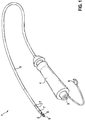
- Fig. 1 to 3 show an exemplary embodiment of a micro-impedance measurement ablation catheter 1 for performing, for example, micro-mapping for diagnostic purposes and / or for monitoring lesion formation during ablation.
- Fig. 1 schematically illustrates the ablation catheter 1 with an ablation electrode 2.
- the ablation electrode 2 is disposed at a distal end of a catheter shaft 5.
- lateral microelectrodes 8 on a lateral surface 18 (FIG. Fig. 2 ) of the ablation electrode 2 and a frontal microelectrode 9 on an end face 17 (FIG. Fig. 2 ) of the ablation electrode 2.
- Several frontal microelectrodes can also be arranged on the end face 17 (not shown).
- Proximal to the ablation electrode 2 are three ring electrodes 7 for the conventional mapping method.
- a catheter handle 4 is arranged.
- the ablation electrode 2, the lateral microelectrodes 8, the frontal microelectrode 9 and the ring electrodes 7 are connected via the catheter shaft 5 through the catheter handle 4 with poles in a plug 3.
- the plug 3 provides a connection for the ablation electrode 2, the lateral microelectrodes 8, the frontal microelectrode 9 and the ring electrodes 7 and optionally a thermocouple to a control device.
- a flushing connection 6 for the flushing of the ablation electrode 2 is led out of the catheter grip 4.
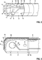
- Fig. 2 shows the catheter head with the ablation electrode 2 and a part of the catheter shaft 5 and one of the ring electrodes 7.
- the ablation electrode 2 is equipped with a frontal microelectrode 9 and four lateral microelectrodes 8.
- the microelectrodes 8, 9 are electrically insulated by LCP foils 10 from the ablation electrode 2.
- the LCP foils each surround a conductor track, each microelectrode 8, 9 being connected to a conductor track (not shown).
- the LCP foils 10 are embedded in recesses in the ablation electrode 2. The depth of the recesses is 0.05 mm.
- the microelectrodes 8, 9 and the LCP foils 10 form a smooth termination with the surface of the ablation electrode 2.
- the LCP foils 10 are guided to a proximal end of the ablation catheter 2 on the surface of the ablation catheter. At the proximal end, the LCP films (with the conductor tracks) are led into an inner region of the catheter shaft 5.
- the LCP sheets 10 may be folded or bent like paper and thus easily guided around an edge of the ablation electrode 2 by a bond 15 in the catheter shaft 5.
- the LCP films 10 are designed so that flushing openings 11 are bypassed well and thus kept free.
- Fig. 3 shows the ablation electrode 2 Fig. 2 cut so that the cross section of a recess to the frontal microelectrode 9 is visible.
- the LCP film 10 is here connected to the ablation electrode 2 by means of an adhesive 14 for the microelectrode 9 at the bottom of the recess.
- a trace 12 eg, a copper trace
- an exposed gold-coated electrode 13 eg, a copper electrode.
- the conductor 12 is shown in dashed lines, since this is completely surrounded by the LCP film 10 (and therefore not directly visible). After proximal, the conductor 12 is electrically isolated passed through the catheter shaft 5 and the catheter handle 4 and finally connected to a corresponding pole of the plug 3.
- Fig. 4 shows a schematic representation of a micro-electrode 20.
- the micro-electrode 20 has in the embodiment shown a circular surface with a diameter D (eg 0.3 mm).
- the microelectrode 20 is electrically isolated from the ablation electrode (not shown) by means of an insulating material 22.
- the insulating material 22 may be, for example, an LCP film.
- a conductive member 21 eg, a copper conductor
- the microelectrode 20 is connected to the line element 21 on its underside.
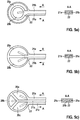
- Fig. 5 shows schematic representations of embodiments of a multi-part microelectrode. In each case, a section along the line A - A is shown.
- Fig. 5 a shows a concentric microelectrode with two segments 20a, 20b.
- a first segment 20a forms an open or closed loop surrounding a second segment 20b in the form of a circular area.
- the two segments 20a, 20b are connected to line elements 21a, 21b.
- the two segments 20a, 20b and the conducting elements 21b, 21b are insulated with the insulating material 22 from the ablation electrode (not shown).
- a two-part microelectrode with two semicircular segments 20a, 20b is shown.
- the two segments 20a, 20b are connected to line elements 21a, 21b.
- the two segments 20a, 20b and the conducting elements 21b, 21b are insulated with the insulating material 22 from the ablation electrode (not shown).
- FIG Fig. 5c A microelectrode with three segments 20a, 20b, 20c is shown in FIG Fig. 5c) shown.
- the three segments 20a, 20b, 20c are connected to line elements 21a, 21b, 21c.
- the three segments 20a, 20b, 20c and the conducting elements 21b, 21b, 21c are insulated with the insulating material 22 from the ablation electrode (not shown).
- Fig. 6 shows a microelectrode 20 having a hole 23.
- the microelectrode 20 is connected to the conducting element 21.
- the microelectrode 20 and the conducting element 21 are insulated with the insulating material 22 from the ablation electrode (not shown). Furthermore, sections along the lines A - A and B - B are shown.
- Fig. 7 shows a catheter head of a rinsed catheter with microelectrodes 20 after Fig. 6 , The scavenging port 11 passes through the hole in the microelectrode 20.
- a catheter head with ring microelectrodes 24a, 24b is shown.
- the two ring microelectrodes 24a, 24b are connected to line elements 21a, 21b.
- the two ring microelectrodes 24a, 24b and the conducting elements 21b, 21b are insulated with the insulating material 22 from the ablation electrode.
- the line elements 21 a, 21 b are completely surrounded by the insulating material 22.
- the section along the line B - B shows the ring microelectrodes 24a, 24b embedded in the insulating material 22.
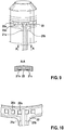
- Fig. 9 shows a catheter head with toothed microelectrodes 25a, 25b.
- the two toothed microelectrodes 25a, 25b are connected to line elements 21a, 21b.
- the two toothed microelectrodes 25a, 25b and the conducting elements 21b, 21b are insulated with the insulating material 22 from the ablation electrode.
- the line elements 21 a, 21 b are completely surrounded by the insulating material 22.
- the terminals of the toothed microelectrodes 25a, 25b to the line elements 21a, 21b is in Fig. 10 shown.
- the two line elements 21a, 21b are connected to connection elements. In this way, the toothed microelectrodes can be connected to only two line elements 21a, 21b.
- Other tooth shapes are possible, such as triangular teeth or semi-circular teeth.
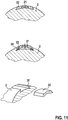
- Fig. 11 shows an attachment of the insulating material 22 without gluing. Instead, the insulating material 22 hooks behind an edge 30 (undercut clamping).
- the insulating material (and / or the microelectrode) can be clipped into a recess so that it hooks behind the edge 30 (middle image of Fig. 11 ) or it can be pushed into the recess (lower picture of Fig. 11 ).
- FIG. 12 An attachment by means of tensioning is shown in a groove.
- Fig. 13 shows a fastening by shrinking.
- the ablation catheter is in this case for a short time cooler than the microelectrodes 20 with their feed line 21.
- the microelectrodes with the leads and the insulating material are arranged in a groove 31. After cooling, the microelectrodes are firmly seated on the ablation electrode.
Landscapes
- Health & Medical Sciences (AREA)
- Life Sciences & Earth Sciences (AREA)
- Surgery (AREA)
- Engineering & Computer Science (AREA)
- Plasma & Fusion (AREA)
- General Health & Medical Sciences (AREA)
- Otolaryngology (AREA)
- Physics & Mathematics (AREA)
- Veterinary Medicine (AREA)
- Biomedical Technology (AREA)
- Heart & Thoracic Surgery (AREA)
- Medical Informatics (AREA)
- Molecular Biology (AREA)
- Animal Behavior & Ethology (AREA)
- Nuclear Medicine, Radiotherapy & Molecular Imaging (AREA)
- Public Health (AREA)
- Cardiology (AREA)
- Surgical Instruments (AREA)
- Measurement And Recording Of Electrical Phenomena And Electrical Characteristics Of The Living Body (AREA)
Abstract
Description
- Die Offenbarung betrifft einen Ablationskatheter mit einer Mikroelektrode sowie ein Verfahren zum Herstellen eines Ablationskatheters.
- Das intrakardiale Mapping (z. B. durch Impedanzmessung zwischen Katheterelektroden) in der Kontaktzone einer Ablationselektrode eines elektrophysiologischen Katheters mit dem Herzgewebe ist bekannt. Das sogenannte "Micro-Mapping" mittels einer oder mehrerer Mikroelektroden an dem Katheter ist ein vielversprechender Ansatz, um für medizinische Diagnose- und Überwachungszwecke während der Ablation zur Behandlung von Herzrhythmusstörungen genutzt zu werden.
- Das Dokument
US 2004/0092806 A1 offenbart einen Ablationskatheter mit Mikroelektroden. Die metallischen Mikroelektroden in Form von Zylindern, Kegeln oder Pilzen sind in Bohrungen in der Ablationselektrode und von dieser elektrisch isoliert eingefügt und im innenliegenden Bereich des Ablationskatheters mit elektrischen Zuleitungen versehen. - Das Dokument
US 2008/0243214 A1 offenbart ebenfalls einen Ablationskatheter mit Mikroelektroden. Die Mikroelektroden sind als Zylinder geformt und in Löchern am Katheterkopf angeordnet. - Das Dokument
EP 3 015 064 A2 offenbart einen Ablationskatheter mit Vertiefungen zur Aufnahme von Mikroelektroden. - Die bekannten Mikroelektroden-Katheter-Konzepte benötigen für die Mikroelektroden einen relativ großen Platzbedarf auf der Ablationselektrode, insbesondere für die Befestigung, die elektrische Isolation und die Kontaktierung mit den elektrischen Zuleitungen. Bei gespülten Ablationskathetern beeinträchtigen die Gestaltung und die Montage der elektrischen Zuleitungsführung in hohem Maße die Führung der Spülleitungen und die Gestaltung der Spülkanäle.
- Als Aufgabe kann angesehen werden, verbesserte Technologien für Ablationskatheter bereitzustellen. Insbesondere soll der Platzbedarf einer Mikroelektrode und deren Zuleitung verringert werden.
- Es sind ein Ablationskatheter nach Anspruch 1 und ein Verfahren zum Herstellen eines Ablationskatheters nach Anspruch 14 offenbart. Weitere Ausführungsformen sind Gegenstand von abhängigen Ansprüchen.
- Nach einem Aspekt ist ein Ablationskatheter bereitgestellt. Der Ablationskatheter weist einen Katheterschaft und eine an einem distalen Ende des Katheterschafts angeordnete Ablationselektrode auf. Des Weiteren sind eine Mikroelektrode und ein Leitungselement vorgesehen. Die Mikroelektrode ist an einer Oberfläche der Ablationselektrode angeordnet. Das Leitungselement ist mit der Mikroelektrode elektrisch leitend verbunden. Das Leitungselement ist von einem Isoliermaterial umgeben, so dass das Leitungselement von der Ablationselektrode elektrisch isoliert ist. Das Isoliermaterial ist mit dem Leitungselement zumindest abschnittsweise an der Oberfläche der Ablationselektrode angeordnet.
- Nach einem weiteren Aspekt ist ein Verfahren zum Herstellen eines Ablationskatheters offenbart. Das Verfahren umfasst die folgenden Schritte: Bereitstellen eines Katheterschafts, Anordnen einer Ablationselektrode an einem distalen Ende des Katheterschafts, Anordnen einer Mikroelektrode an einer Oberfläche der Ablationselektrode, und Bereitstellen eines Leitungselements, das mit der Mikroelektrode elektrisch leitend verbunden ist. Das Leitungselement wird von einem Isoliermaterial umgeben, so dass das Leitungselement von der Ablationselektrode elektrisch isoliert ist. Das Isoliermaterial wird mit dem Leitungselement zumindest abschnittsweise an der Oberfläche der Ablationselektrode angeordnet.
- Es können mehrere Mikroelektroden an der Ablationselektrode angeordnet sein, wobei jede der mehreren Mikroelektroden von der Ablationselektrode elektrisch isoliert sein kann. Jede der mehreren Mikroelektroden kann mit einem ausschließlich ihr zugeordneten Leitungselement verbunden sein. Es kann auch vorgesehen sein, dass mehrere Mikroelektroden mit einem gemeinsamen Leitungselement verbunden sind. Auch Mischformen sind möglich. Beispielsweise kann eine erste Gruppe von mehreren Mikroelektroden mit einem gemeinsamen ersten Leitungselement verbunden sein und eine zweite Gruppe von mehreren Mikroelektroden kann mit einem gemeinsamen zweiten Leitungselement verbunden sein. Die Mikroelektroden können vielfältig geformt sein, z. B. rund, oval oder halbkreisförmig. Die Mikroelektroden können auf der Oberfläche der Ablationselektrode in verschiedene Richtungen zeigen.
- Die Mikroelektrode kann an einer Stirnfläche der Ablationselektrode oder an einer Mantelfläche der Ablationselektrode angeordnet sein. Wenn mehrere Mikroelektroden vorgesehen sind, können eine oder mehrere Mikroelektroden an der Stirnfläche der Ablationselektrode angeordnet sein. Ergänzend oder alternativ können eine oder mehrere Mikroelektroden an der Mantelfläche der Ablationselektrode angeordnet sein. Mehrere Mikroelektroden können an der Stirnfläche und/oder der Mantelfläche der Ablationselektrode gleichmäßig verteilt sein. Die Stirnfläche der Ablationselektrode kann auch als distales Ende der Ablationselektrode bezeichnet werden.
- Als distales Ende des Katheterschafts wird das Ende verstanden, das bei der Verwendung des Katheters (beispielsweise während der Ablation) in den Körper des Patienten eingeführt wird. Das distale Ende des Katheterschafts mit der Ablationselektrode kann auch als Katheterkopf bezeichnet werden. Ein proximales Ende des Katheterschafts ist das Ende, das bei der Verwendung des Katheters außerhalb des Körpers verbleibt. An dem proximalen Ende des Katheterschafts kann ein Kathetergriff gebildet sein. An dem Kathetergriff kann eine Anschlusseinrichtung zum Anschluss der Ablationselektrode und der Mikroelektrode(n) an eine Steuervorrichtung vorgesehen sein.
- Es kann vorgesehen sein, dass das mit dem Isoliermaterial umgebene Leitungselement wenigstens abschnittsweise in einer an der Oberfläche der Ablationselektrode gebildeten Aussparung angeordnet ist. Es kann ebenfalls vorgesehen sein, dass die Mikroelektrode und das mit dem Isoliermaterial umgebene Leitungselement in einer an der Oberfläche der Ablationselektrode gebildeten Aussparung angeordnet sind. Die Mikroelektrode und das die Mikroelektrode umgebende Leitungsmaterial können als in die Oberfläche der Ablationselektrode eingebettet angesehen werden. Die Aussparung kann an der Stirnfläche und/oder an der Mantelfläche der Ablationselektrode gebildet sein. Wenn mehrere Mikroelektroden vorgesehen sind, können mehrere Aussparungen an der Oberfläche der Ablationselektrode gebildet sein, derart, dass jede Mikroelektrode und/ oder das jeweilige Leitungselement in einer der mehreren Aussparungen angeordnet sind. Die Aussparung (oder ggf. die Aussparungen) kann eine Tiefe von 0,05 mm oder weniger (z. B. 0,03 mm oder 0,01 mm) haben.
- Die Mikroelektrode und/oder das mit dem Isoliermaterial umgebene Leitungselement können in die Aussparung geklebt sein. Alternativ können die Mikroelektrode und/oder das Isoliermaterial mittels einer Klemmbefestigung, Umspannen, Aufschrumpfen oder Aufdehnen befestigt sein. Andere Möglichkeiten zur Befestigung der Mikroelektrode und/oder des mit dem Isoliermaterial umgebenen Leitungselements sind ebenfalls denkbar.
- Die Mikroelektrode kann von der Ablationselektrode elektrisch isoliert sein, beispielsweise mittels des Isoliermaterials.
- Das Isoliermaterial kann Polyimid (PI), Polyurethan (PUR), Polyether-Block-Amid (PEBA) oder ein Flüssigkristallpolymer (LCP - liquid crystal polymer) sein. Flüssigkristallpolymere sind einfach zu verarbeiten (auch bei kurzzeitig 100°C noch formstabil und beständig) und biokompatibel, was sie besonders zur Anwendung bei einem Ablationskatheter geeignet macht. Das Isoliermaterial kann als flexibles Folienmaterial bereitgestellt werden, z. B. als LCP-Folie oder eine Folie aus einem der anderen vorgenannten Materialien.
- Die Mikroelektrode und/oder das mit dem Isoliermaterial umgebene Leitungselement können formschlüssig (oder passgenau) in der Aussparung angeordnet sein.
- Das Leitungselement kann ein Metall (z. B. Kupfer) oder eine Metalllegierung enthalten oder aus einem Metall (z. B. Kupfer) bzw. einer Metalllegierung bestehen. Das Leitungselement kann als Leiterbahn ausgebildet sein. In einer Ausführungsform ist das Leitungselement als Kupferleiterbahn gebildet, die von einer flexiblen LCP-Folie zur elektrischen Isolierung umgeben ist.
- Die Mikroelektrode (oder die Mikroelektroden) kann ein Metall (z. B. Kupfer) oder eine Metalllegierung enthalten oder aus einem Metall (z. B. Kupfer) bzw. einer Metalllegierung bestehen. Die Mikroelektrode kann beschichtet sein, beispielsweise mit einem Metall (z. B. Gold, Platin oder einem anderen galvanisierbaren biokompatiblen Metall) oder einer Metalllegierung. Die Mikroelektrode kann als flächige Mikroelektrode gebildet sein, wobei die Ausdehnung der Mikroelektrode in zwei Dimensionen (Fläche der Mikroelektrode) wesentlich größer ist als in die dritte Dimension (Höhe der Mikroelektrode). Die Ausdehnung in der Fläche (z. B. der Durchmesser der Mikroelektrode) kann 0,3 mm betragen. Beispielsweise kann die Mikroelektrode (oder ggf. die Mikroelektroden) als flächige (oder leicht gewölbte) Mikroelektrode aus Kupfer gebildet sein, die mit Gold beschichtet ist.
- Die Dimensionen orientieren sich am Umfang und der axialen Länge der Ablationselektrode (z. B. Umfang U = 7 mm und Länge L = 3 bis 8 mm). Der Elektrodendurchmesser D der Mikroelektroden inklusive Isolationskanten ist maximal D = U/n, wobei n die Anzahl der Mikroelektroden ist. Wichtig ist der von den Mikroelektroden inklusive Isolationskanten abgedeckte (und somit nicht wirksame) Flächenanteil der Ablationselektrode. Dieser sollte etwa unter einem Drittel liegen. Die Umfangsformen der Mikroelektroden können so gestaltet sein, dass die freie Kontaktfläche der Ablationselektrode in jeder Roll- und Kippwinkelstellung mit dem Herzgewebe groß genug für eine effiziente Ablationsstromabgabe ist.
- Es kann vorgesehen sein, dass die Mikroelektrode und/oder das mit dem Isoliermaterial umgebene Leitungselement einen glatten Abschluss mit der Oberfläche der Ablationselektrode bilden. Insbesondere kann ein Übergang von der Mikroelektrode und/oder dem Isoliermaterial zu der Oberfläche der Ablationselektrode frei von Unebenheiten oder Kanten sein.
- Das mit dem Isoliermaterial umgebene Leitungselement kann von der Mikroelektrode bis zu einem distalen Ende des Katheterschafts an der Oberfläche der Ablationselektrode angeordnet sein und an dem distalen Ende des Katheterschafts in einen Innenbereich des Katheterschafts geführt sein. An dem distalen Ende des Katheterschafts ist ein Übergang vom Material der Ablationselektrode (in der Regel ein Metall, z. B. Gold oder Platin, oder eine Metalllegierung) zum Material des Katheterschafts (z. B. ein Kunststoff). An diesem Übergang kann das Leitungselement mit dem Isoliermaterial in den Innenbereich des Katheterschafts geführt werden.
- In der Ablationselektrode kann eine Spülöffnung gebildet sein. Die Spülöffnung kann mit einer im Innenbereich des Katheterschafts angeordneten Spülleitung verbunden sein. Es können auch mehrere Spülöffnungen in der Ablationselektrode gebildet sein, die mit der Spülleitung verbunden sind. Anordnungen und Geometrien von Spülleitungen sind bekannt. Beispielsweise können die in dem Dokument
EP 2 380 517 A1 offenbarten Ausführungsformen (insbesondere die in denFig. 3B und4B gezeigten Varianten) mit der vorliegenden Offenbarung kombiniert werden. - Die Mikroelektrode kann mit einem Loch gebildet sein und derart auf der Oberfläche der Ablationselektrode angeordnet sein, dass das Loch der Mikroelektrode zumindest abschnittsweise auf der Spülöffnung angeordnet. In diesem Fall kann eine Spülung durch das Loch in der Mikroelektrode erfolgen. Dies kann folgende Vorteile haben:
- 1. Erweiterte Flächenausnutzung und weitere Platzierungsmöglichkeiten für Mikroelektroden.
- 2. Schutz vor Überhitzung und daraus resultierende Thrombenbildung an den Materialübergängen: Isolationskante (Polymer) zur Mikro- und Ablationselektrode.
- Die Mikroelektrode kann als Ringelektrode gebildet sein, welche die Ablationselektrode um deren Umfang herum umgibt.
- Die Mikroelektrode kann als gezahnte Mikroelektrode gebildet sein.
- Merkmale, die für die Mikroelektrode offenbart sind, können auf Ausführungsformen mit mehreren Mikroelektroden übertragen werden. Die Merkmale, welche im Zusammenhang mit dem Ablationskatheter offenbart sind, können in analoger Weise auf das Verfahren zum Herstellen des Ablationskatheters angewendet werden und umgekehrt.
- Im Folgenden werden beispielhafte Ausführungsformen unter Bezugnahme auf Figuren näher erläutert. Es zeigen:
- Fig. 1
- eine schematische Darstellung eines Ablationskatheters mit Mikroelektroden,
- Fig. 2
- eine schematische Darstellung eines Katheterkopfs des Katheters aus
Fig. 1 , - Fig. 3
- einen Querschnitt des Katheterkopfs aus
Fig. 2 , - Fig. 4
- eine schematische Darstellung einer Mikroelektrode,
- Fig. 5
- schematische Darstellungen von weiteren Ausführungsformen einer Mikroelektrode,
- Fig. 6
- eine schematische Darstellung einer anderen Ausführungsform einer Mikroelektrode,
- Fig. 7
- eine schematische Darstellung eines Katheterkopfs mit Mikroelektroden gemäß der Ausführungsform nach
Fig. 6 , - Fig. 8
- eine schematische Darstellung eines Katheterkopfs, wobei die Mikroelektroden als Ringelektroden ausgeführt sind,
- Fig. 9
- eine schematische Darstellung eines Katheterkopfs, wobei die Mikroelektroden als gezahnte Mikroelektroden ausgeführt sind,
- Fig. 10
- eine schematische Darstellung der Anschlüsse der Leitungselemente an die gezahnten Mikroelektroden aus
Fig. 9 , und - Fig. 11 - 13
- verschiedene Arten der Befestigung der Mikroelektroden an der Ablationselektrode.
- Für gleiche Komponenten werden die gleichen Bezugszeichen verwendet.
-
Fig. 1 bis 3 zeigen eine beispielhafte Ausführungsform eines Ablationskatheters 1 mit Mikroimpedanzmessfunktion, um beispielsweise Mikro-Mapping zu diagnostischen Zwecken und/oder zur Überwachung der Läsionsbildung während der Ablation durchzuführen. -
Fig. 1 stellt schematisch den Ablationskatheter 1 mit einer Ablationselektrode 2 dar. Die Ablationselektrode 2 ist an einem distalen Ende eines Katheterschafts 5 angeordnet. An der Ablationselektrode 2 sind laterale Mikroelektroden 8 auf einer Mantelfläche 18 (Fig. 2 ) der Ablationselektrode 2 und eine frontale Mikroelektrode 9 an einer Stirnfläche 17 (Fig. 2 ) der Ablationselektrode 2 angeordnet. Es können auch mehrere frontale Mikroelektroden an der Stirnfläche 17 angeordnet sein (nicht dargestellt). Proximal der Ablationselektrode 2 befinden sich drei Ringelektroden 7 für das herkömmliche Mapping-Verfahren. An einem proximalen Ende des Katheterschafts 5 ist ein Kathetergriff 4 angeordnet. Die Ablationselektrode 2, die lateralen Mikroelektroden 8, die frontale Mikroelektrode 9 und die Ringelektroden 7 sind über den Katheterschaft 5 durch den Kathetergriff 4 mit Polen in einem Stecker 3 verbunden. Der Stecker 3 stellt einen Anschluss für die Ablationselektrode 2, die lateralen Mikroelektroden 8, die frontale Mikroelektrode 9 und die Ringelektroden 7 und ggf ein Thermoelement an eine Steuereinrichtung bereit. Ein Spülanschluss 6 für die Spülung der Ablationselektrode 2 ist aus dem Kathetergriff 4 herausgeführt. -
Fig. 2 zeigt den Katheterkopf mit der Ablationselektrode 2 sowie einem Teil des Katheterschafts 5 und einer der Ringelektroden 7. Die Ablationselektrode 2 ist mit einer frontalen Mikroelektrode 9 und vier lateralen Mikroelektroden 8 ausgestattet. Die Mikroelektroden 8, 9 sind durch LCP-Folien 10 von der Ablationselektrode 2 elektrisch isoliert. Die LCP-Folien umgeben jeweils eine Leiterbahn, wobei jede Mikroelektrode 8, 9 mit einer Leiterbahn verbunden ist (nicht dargestellt). Die LCP-Folien 10 sind in Aussparungen in der Ablationselektrode 2 eingelassen. Die Tiefe der Aussparungen beträgt 0,05 mm. Die Mikroelektroden 8, 9 und die LCP-Folien 10 bilden einen glatten Abschluss mit der Oberfläche der Ablationselektrode 2. Die LCP-Folien 10 sind bis zu einem proximalen Ende des Ablationskatheters 2 an der Oberfläche des Ablationskatheters geführt. An dem proximalen Ende werden die LCP-Folien (mit den Leiterbahnen) in einen Innenbereich des Katheterschafts 5 geführt. Die LCP-Folien 10 können wie Papier gefaltet oder gebogen und somit leicht um eine Kante der Ablationselektrode 2 durch eine Klebung 15 in den Katheterschaft 5 geführt werden. Die LCP-Folien 10 sind so gestaltet, dass Spülöffnungen 11 gut umgangen werden und damit freigehalten sind. -
Fig. 3 zeigt die Ablationselektrode 2 ausFig. 2 so geschnitten, dass der Querschnitt einer Aussparung bis zur frontalen Mikroelektrode 9 sichtbar ist. Die LCP-Folie 10 ist hier mittels eines Klebers 14 für die Mikroelektrode 9 am Grund der Aussparung mit der Ablationselektrode 2 verbunden. Innerhalb der LCP-Folie 10 befindet sich eine Leiterbahn 12 (z.B. eine Kupferleiterbahn), die distal mit einer exponierten goldbeschichteten Elektrode 13 (z. B. eine Kupferelektrode) elektrisch leitend verbunden ist. Die Leiterbahn 12 ist gestrichelt gezeichnet, da diese vollständig von der LCP-Folie 10 umgeben (und daher nicht direkt sichtbar) ist. Nach proximal ist die Leiterbahn 12 elektrisch isoliert durch den Katheterschaft 5 und den Kathetergriff 4 geführt und schließlich mit einem entsprechenden Pol des Steckers 3 verbunden. -
Fig. 4 zeigt eine schematische Darstellung einer Mikroelektrode 20. Die Mikroelektrode 20 hat in der gezeigten Ausführungsform eine kreisförmige Oberfläche mit einem Durchmesser D (z. B. 0,3 mm). Die Mikroelektrode 20 ist mittels eines Isoliermaterials 22 von der Ablationselektrode (nicht dargestellt) elektrisch isoliert. Das Isoliermaterial 22 kann beispielsweise eine LCP-Folie sein. Ein Leitungselement 21 (z. B. ein Kupferleiter) ist von dem Isoliermaterial umgeben, wie für den Querschnitt entlang der Linie A - A gezeigt ist. Des Weiteren ist ein Schnitt entlang der Linie B - B gezeigt. Die Mikroelektrode 20 ist an ihrer Unterseite mit dem Leitungselement 21 verbunden. -
Fig. 5 zeigt schematische Darstellungen von Ausführungsformen einer mehrteiligen Mikroelektrode. Es ist jeweils auch ein Schnitt entlang der Linie A - A dargestellt. -
Fig. 5 a) zeigt eine konzentrische Mikroelekrode mit zwei Segmenten 20a, 20b. Ein erstes Segment 20a bildet einen offenen odereinen geschlossenen Kreis, der ein zweites Segment 20b in Form einer Kreisfläche umgibt. Die beiden Segmente 20a, 20b sind mit Leitungselementen 21a, 21b verbunden. Die beiden Segmente 20a, 20b und die Leitungselemente 21b, 21b sind mit dem Isoliermaterial 22 von der Ablationselektrode (nicht dargestellt) isoliert. - In
Fig. 5 b) ist eine zweiteilige Mikroelektrode mit zwei halbkreisförmigen Segmenten 20a, 20b dargestellt. Die beiden Segmente 20a, 20b sind mit Leitungselementen 21a, 21b verbunden. Die beiden Segmente 20a, 20b und die Leitungselemente 21b, 21b sind mit dem Isoliermaterial 22 von der Ablationselektrode (nicht dargestellt) isoliert. - Eine Mikroelektrode mit drei Segmenten 20a, 20b, 20c ist in
Fig. 5 c) gezeigt. Die drei Segmente 20a, 20b, 20c sind mit Leitungselementen 21a, 21b, 21c verbunden. Die drei Segmente 20a, 20b, 20c und die Leitungselemente 21b, 21b, 21c sind mit dem Isoliermaterial 22 von der Ablationselektrode (nicht dargestellt) isoliert. -
Fig. 6 zeigt eine Mikroelektrode 20 mit einem Loch 23. Die Mikroelektrode 20 ist mit dem Leitungselement 21 verbunden. Die Mikroelektrode 20 und das Leitungselement 21 sind mit dem Isoliermaterial 22 von der Ablationselektrode (nicht dargestellt) isoliert. Des Weiteren sind Schnitte entlang der Linien A - A und B - B dargestellt.Fig. 7 zeigt einen Katherkopf eines gespülten Katheters mit Mikroelektroden 20 nachFig. 6 . Die Spülöffnung 11 führt durch das Loch in der Mikroelektrode 20. - In
Fig. 8 ist ein Katheterkopf mit Ring-Mikroelektroden 24a, 24b gezeigt. Die beiden Ring-Mikroelektroden 24a, 24b sind mit Leitungselementen 21a, 21b verbunden. Die beiden Ring-Mikroelektroden 24a, 24b und die Leitungselemente 21b, 21b sind mit dem Isoliermaterial 22 von der Ablationselektrode isoliert. Wie im Schnitt entlang der Linie A - A gezeigt ist, sind die Leitungselemente 21a, 21b vollständig von dem Isoliermaterial 22 umgeben. Der Schnitt entlang der Linie B - B zeigt die im Isoliermaterial 22 eingebetteten Ring-Mikroelektroden 24a, 24b. -
Fig. 9 zeigt einen Katheterkopf mit gezahnten Mikroelektroden 25a, 25b. Die beiden gezahnten Mikroelektroden 25a, 25b sind mit Leitungselementen 21a, 21b verbunden. Die beiden gezahnten Mikroelektroden 25a, 25b und die Leitungselemente 21b, 21b sind mit dem Isoliermaterial 22 von der Ablationselektrode isoliert. Wie im Schnitt entlang der Linie A - A gezeigt ist, sind die Leitungselemente 21a, 21b vollständig von dem Isoliermaterial 22 umgeben. Die Anschlüsse der gezahnten Mikroelektroden 25a, 25b an die Leitungselemente 21a, 21b ist inFig. 10 dargestellt. Die beiden Leitungselemente 21a, 21b sind mit Anschlusselementen verbunden. Auf diese Art können die gezahnten Mikroelektroden mit lediglich zwei Leitungselementen 21a, 21b verbunden werden. Weitere Zahnformen sind möglich, wie beispielsweise dreieckige Zähne oder halbkreisförmige Zähne. -
Fig. 11 zeigt eine Befestigung des Isoliermaterials 22 ohne Klebung. Stattdessen hakt das Isoliermaterial 22 hinter einer Kante 30 ein (Hinterschnitt-Klemmung). Das Isoliermaterial (und/oder die Mikroelektrode) kann in eine Aussparung eingeklipst werden, sodass sie hinter der Kante 30 verhakt (mittleres Bild vonFig. 11 ) oder sie kann in die Aussparung hinein geschoben werden (unteres Bild vonFig. 11 ). - In
Fig. 12 ist eine Befestigung mittels Umspannung in einer Nut dargestellt. -
Fig. 13 zeigt eine Befestigung mittels Aufschrumpfen. Der Ablationskatheter ist hierbei kurzzeitig kühler als die Mikroelektroden 20 mit deren Zuleitung 21. Die Mikroelektroden mit den Zuleitungen und dem Isoliermaterial werden in einer Nut 31 angeordnet. Nach dem Abkühlen sitzen die Mikroelektroden fest auf der Ablationselektrode. Alternativ ist auch ein Aufdehnen der Mikroelektroden mit dem Isoliermaterial und den Zuleitungen und ein anschließendes Einrasten in der Nut möglich (nicht dargestellt). - Der Ablationskatheter nach den offenbarten Ausführungsformen kann die folgenden Vorteile aufweisen:
- 1. Die Mikroelektroden haben einen sehr geringen Platzbedarf an der Ablationselektrode, insbesondere für die Befestigung, die elektrische Isolation und die Kontaktierung mit den elektrischen Zuleitungen.
- 2. Die Gestaltung und die Montage der elektrischen Zuleitungsführung ist relativ einfach durch Kleben, Falten und Biegen zu bewältigen und beeinträchtigt nicht die Führung der Spülleitungen und der Spülkanäle in der Ablationselektrode.
- 3. Bei der Verwendung von mehreren Mikroelektroden kann gewährleistet sein, dass während der Ablation immer mindestens eine Mikroelektrode in Gewebekontakt ist.
- 4. Insbesondere die Ausführung eines Ablationskatheters mit partiellen LCP-Oberflächen ist biokompatibel und EO-sterilisierbar.
- 5. Elektrode mit Loch für bessere Flächenausnutzung und weitere Platzierungsmöglichkeiten für Mikroelektroden und Schutz vor Überhitzung und daraus resultierender Thrombenbildung an den Materialübergängen: Isolationskante (Polymer) zur Mikro- und Ablationselektrode.
- Die in der Beschreibung, den Ansprüchen und den Figuren offenbarten Merkmale können für die Verwirklichung von Ausführungsformen sowohl einzeln als auch in beliebiger Kombination miteinander relevant sein.
-
- 1
- Ablationskatheter
- 2
- Ablationselektrode
- 3
- Stecker
- 4
- Kathetergriff
- 5
- Katheterschaft
- 6
- Spülanschluss
- 7
- Ringelektroden
- 8
- Mikroelektrode lateral
- 9
- Mikroelektrode frontal
- 10
- LCP-Folie
- 11
- Spülöffnung
- 12
- Leiterbahn
- 13
- Elektrode
- 14
- Kleber für die Mikroelektrode
- 15
- Klebung der Ablationselektrode mit dem Katheterschaft
- 16
- distales Ende des Katheterschafts
- 17
- Stirnfläche der Ablationselektrode
- 18
- Mantelfläche der Ablationselektrode
- 20(a,b,c)
- Mikroelektrode
- 21(a,b,c)
- Leiterelement
- 22(a,b,c)
- Isoliermaterial
- 23
- Loch
- 24(a,b)
- Ring-Mikroelektrode
- 25(a,b)
- gezahnte Mikroelektrode
- 30
- Kante
- 31
- Nut
Claims (14)
- Ablationskatheter (1), mit- einem Katheterschaft (5),- einer Ablationselektrode (2), die an einem distalen Ende des Katheterschafts (5) angeordnet ist,- einer Mikroelektrode (20; 24; 25), die an einer Oberfläche der Ablationselektrode (2) angeordnet ist, und- einem Leitungselement (21), das mit der Mikroelektrode (20; 24; 25) elektrisch leitend verbunden ist,wobei das Leitungselement (12; 21) von einem Isoliermaterial (10; 22) umgeben ist, so dass das Leitungselement (12; 21) von der Ablationselektrode (2) elektrisch isoliert ist, und wobei das Isoliermaterial (10; 22) mit dem Leitungselement (12; 21) zumindest abschnittsweise an der Oberfläche der Ablationselektrode (2) angeordnet ist.
- Ablationskatheter (1) nach Anspruch 1, wobei das mit dem Isoliermaterial (10; 22) umgebene Leitungselement (12; 21) wenigstens abschnittsweise in einer an der Oberfläche der Ablationselektrode (2) gebildeten Aussparung angeordnet ist.
- Ablationskatheter (1) nach Anspruch 1, wobei die Mikroelektrode (20; 24; 25) und das mit dem Isoliermaterial (10; 22) umgebene Leitungselement (12; 21) in einer an der Oberfläche der Ablationselektrode (2) gebildeten Aussparung angeordnet sind.
- Ablationskatheter (1) nach Anspruch 2 oder 3, wobei die Mikroelektrode (20; 24; 25) und/oder das mit dem Isoliermaterial (10; 22) umgebene Leitungselement (12; 21) in die Aussparung geklebt sind.
- Ablationskatheter (1) nach einem der vorhergehenden Ansprüche, wobei die Mikroelektrode (20; 24; 25) mittels des Isoliermaterials (10; 22) von der Ablationselektrode (2) elektrisch isoliert ist.
- Ablationskatheter (1) nach einem der vorhergehenden Ansprüche, wobei das Isoliermaterial (10; 22) ein flexibles Folienmaterial ist.
- Ablationskatheter (1) nach einem der vorhergehenden Ansprüche, wobei das Isoliermaterial (10; 22) ein Flüssigkristallpolymer ist.
- Ablationskatheter (1) nach einem der vorhergehenden Ansprüche, wobei die Mikroelektrode (20; 24; 25) und/oder das mit dem Isoliermaterial (10; 22) umgebene Leitungselement (12; 21) einen glatten Abschluss mit der Oberfläche der Ablationselektrode (2) bilden.
- Ablationskatheter (1) nach einem der vorhergehenden Ansprüche, wobei das mit dem Isoliermaterial (10; 22) umgebene Leitungselement (12; 21) von der Mikroelektrode (20; 24; 25) bis zu einem distalen Ende (16) des Katheterschafts (5) an der Oberfläche der Ablationselektrode (2) angeordnet ist und an dem distalen Ende (16) des Katheterschafts (5) in einen Innenbereich des Katheterschafts (5) geführt ist.
- Ablationskatheter (1) nach einem der vorhergehenden Ansprüche, wobei in der Ablationselektrode (2) eine Spülöffnung (11) gebildet ist, und wobei die Spülöffnung (11) mit einer im Innenbereich des Katheterschafts angeordneten Spülleitung verbunden ist.
- Ablationskatheter (1) nach Anspruch 10, wobei die Mikroelektrode (20) mit einem Loch (23) gebildet ist, und derart auf der Oberfläche der Ablationselektrode (2) angeordnet ist, dass das Loch (23) der Mikroelektrode (20) zumindest abschnittsweise auf der Spülöffnung (11) angeordnet.
- Ablationskatheter (1) nach einem der Ansprüche 1 bis 10, wobei die Mikroelektrode (24) als Ringelektrode gebildet ist, welche die Ablationselektrode (2) um deren Umfang herum umgibt.
- Ablationskatheter (1) nach einem der Ansprüche 1 bis 10, wobei die Mikroelektrode (25) als gezahnte Mikroelektrode gebildet ist.
- Verfahren zum Herstellen eines Ablationskatheters (1), mit folgenden Schritten:- Bereitstellen eines Katheterschafts,- Anordnen einer Ablationselektrode (2) an einem distalen Ende des Katheterschafts,- Anordnen einer Mikroelektrode (20; 24; 25) an einer Oberfläche der Ablationselektrode (2), und- Bereitstellen eines Leitungselements (12; 21), das mit der Mikroelektrode (20; 24; 25) elektrisch leitend verbunden ist,wobei das Leitungselement (12; 21) von einem Isoliermaterial (10; 22) umgeben wird, so dass das Leitungselement (12; 21) von der Ablationselektrode (2) elektrisch isoliert ist, und wobei das Isoliermaterial (10; 22) mit dem Leitungselement (12; 21) zumindest abschnittsweise an der Oberfläche der Ablationselektrode (2) angeordnet wird.
Priority Applications (3)
| Application Number | Priority Date | Filing Date | Title |
|---|---|---|---|
| CN201811153738.6A CN109692038A (zh) | 2017-10-23 | 2018-09-30 | 带有微电极的消融导管及其制造方法 |
| US16/157,697 US20190117299A1 (en) | 2017-10-23 | 2018-10-11 | Ablation catheter with microelectrode and method for producing the same |
| MX2018012552A MX2018012552A (es) | 2017-10-23 | 2018-10-12 | Cateter de ablacion con microelectrodo y procedimiento para la fabricacion de un cateter de ablacion. |
Applications Claiming Priority (1)
| Application Number | Priority Date | Filing Date | Title |
|---|---|---|---|
| DE102017124651 | 2017-10-23 |
Publications (2)
| Publication Number | Publication Date |
|---|---|
| EP3473200A1 true EP3473200A1 (de) | 2019-04-24 |
| EP3473200B1 EP3473200B1 (de) | 2020-10-07 |
Family
ID=61231068
Family Applications (1)
| Application Number | Title | Priority Date | Filing Date |
|---|---|---|---|
| EP18156706.6A Not-in-force EP3473200B1 (de) | 2017-10-23 | 2018-02-14 | Ablationskatheter mit mikroelektrode und verfahren zum herstellen eines ablationskatheters |
Country Status (4)
| Country | Link |
|---|---|
| US (1) | US20190117299A1 (de) |
| EP (1) | EP3473200B1 (de) |
| CN (1) | CN109692038A (de) |
| MX (1) | MX2018012552A (de) |
Families Citing this family (1)
| Publication number | Priority date | Publication date | Assignee | Title |
|---|---|---|---|---|
| JP7701855B2 (ja) * | 2021-11-02 | 2025-07-02 | 株式会社カネカ | 電極カテーテルおよび電極カテーテルの製造方法 |
Citations (10)
| Publication number | Priority date | Publication date | Assignee | Title |
|---|---|---|---|---|
| DE10008918A1 (de) * | 2000-02-25 | 2001-08-30 | Biotronik Mess & Therapieg | Ablationskatheter zur Erzeugung linearer Läsionen in Herzmuskelgewebe |
| US20040092806A1 (en) | 2001-12-11 | 2004-05-13 | Sagon Stephen W | Microelectrode catheter for mapping and ablation |
| US20080243214A1 (en) | 2007-03-26 | 2008-10-02 | Boston Scientific Scimed, Inc. | High resolution electrophysiology catheter |
| EP2380517A1 (de) | 2010-04-20 | 2011-10-26 | VascoMed GmbH | Elektrode für einen elektrophysiologischen Ablationskatheter |
| US20140081111A1 (en) * | 2012-09-18 | 2014-03-20 | Boston Scientific Scimed, Inc. | Map and ablate closed-loop cooled ablation catheter |
| WO2015183635A1 (en) * | 2014-05-30 | 2015-12-03 | Boston Scientific Scimed, Inc. | Double micro-electrode catheter |
| EP3009092A1 (de) * | 2014-10-14 | 2016-04-20 | Biosense Webster (Israel) Ltd. | Wirksame parasitäre kapazitätsminimierung für mikro- ablationselektrode |
| EP3015064A2 (de) | 2014-10-28 | 2016-05-04 | Biosense Webster (Israel) Ltd. | Korbkatheter mit mikroelektrodenanordnung-distalspitze |
| EP3040043A1 (de) * | 2014-12-30 | 2016-07-06 | Biosense Webster (Israel) Ltd. | Katheter mit elektrode mit flüssigkeitsgekühlter spitze mit porösem substrat und hochdichten oberflächenmikroelektroden |
| WO2017070559A1 (en) * | 2015-10-21 | 2017-04-27 | St. Jude, Cardiology Division, Inc. | High density electrode mapping catheter |
Family Cites Families (5)
| Publication number | Priority date | Publication date | Assignee | Title |
|---|---|---|---|---|
| US8814857B2 (en) * | 2010-12-17 | 2014-08-26 | St. Jude Medical, Atrial Filbrillation Division, Inc. | Irrigated ablation electrode assemblies |
| US10743932B2 (en) * | 2011-07-28 | 2020-08-18 | Biosense Webster (Israel) Ltd. | Integrated ablation system using catheter with multiple irrigation lumens |
| CN103027750B (zh) * | 2012-11-23 | 2015-02-11 | 刘宗军 | 一种经皮肾动脉内电消融球囊射频导管 |
| CN103989521B (zh) * | 2014-05-16 | 2017-11-17 | 上海微创电生理医疗科技有限公司 | 一种导管消融装置及其射频消融导管 |
| CN107260297A (zh) * | 2017-06-30 | 2017-10-20 | 上海微创电生理医疗科技股份有限公司 | 一种射频消融导管及射频消融系统 |
-
2018
- 2018-02-14 EP EP18156706.6A patent/EP3473200B1/de not_active Not-in-force
- 2018-09-30 CN CN201811153738.6A patent/CN109692038A/zh active Pending
- 2018-10-11 US US16/157,697 patent/US20190117299A1/en not_active Abandoned
- 2018-10-12 MX MX2018012552A patent/MX2018012552A/es unknown
Patent Citations (10)
| Publication number | Priority date | Publication date | Assignee | Title |
|---|---|---|---|---|
| DE10008918A1 (de) * | 2000-02-25 | 2001-08-30 | Biotronik Mess & Therapieg | Ablationskatheter zur Erzeugung linearer Läsionen in Herzmuskelgewebe |
| US20040092806A1 (en) | 2001-12-11 | 2004-05-13 | Sagon Stephen W | Microelectrode catheter for mapping and ablation |
| US20080243214A1 (en) | 2007-03-26 | 2008-10-02 | Boston Scientific Scimed, Inc. | High resolution electrophysiology catheter |
| EP2380517A1 (de) | 2010-04-20 | 2011-10-26 | VascoMed GmbH | Elektrode für einen elektrophysiologischen Ablationskatheter |
| US20140081111A1 (en) * | 2012-09-18 | 2014-03-20 | Boston Scientific Scimed, Inc. | Map and ablate closed-loop cooled ablation catheter |
| WO2015183635A1 (en) * | 2014-05-30 | 2015-12-03 | Boston Scientific Scimed, Inc. | Double micro-electrode catheter |
| EP3009092A1 (de) * | 2014-10-14 | 2016-04-20 | Biosense Webster (Israel) Ltd. | Wirksame parasitäre kapazitätsminimierung für mikro- ablationselektrode |
| EP3015064A2 (de) | 2014-10-28 | 2016-05-04 | Biosense Webster (Israel) Ltd. | Korbkatheter mit mikroelektrodenanordnung-distalspitze |
| EP3040043A1 (de) * | 2014-12-30 | 2016-07-06 | Biosense Webster (Israel) Ltd. | Katheter mit elektrode mit flüssigkeitsgekühlter spitze mit porösem substrat und hochdichten oberflächenmikroelektroden |
| WO2017070559A1 (en) * | 2015-10-21 | 2017-04-27 | St. Jude, Cardiology Division, Inc. | High density electrode mapping catheter |
Also Published As
| Publication number | Publication date |
|---|---|
| EP3473200B1 (de) | 2020-10-07 |
| US20190117299A1 (en) | 2019-04-25 |
| MX2018012552A (es) | 2019-07-15 |
| CN109692038A (zh) | 2019-04-30 |
Similar Documents
| Publication | Publication Date | Title |
|---|---|---|
| EP1878462B1 (de) | Einführvorrichtung | |
| DE69928234T2 (de) | Implantierbare medizinische elektrodenkontakte | |
| DE69924182T2 (de) | Multielement-Spitzenelektroden für Kartierungskatheter | |
| EP1127552B1 (de) | Ablationskatheter zur Erzeugung linearer Läsionen in Herzmuskelgewebe | |
| EP2658444B1 (de) | Verfahren zur bereitstellung eines effizienten biosensors, sowie entsprechende biosensor, substrat und insertionskit | |
| DE60130536T2 (de) | Analytensensor | |
| DE69716940T2 (de) | Elektro-physiologischer katheter mit elektrode in form eines bullauges | |
| DE4402058C1 (de) | Implantierbares, passageres Elektrodenkabel | |
| EP4364791B1 (de) | Elektrodenanordnung zur elektrischen stimulation sowie verfahren zur herstellung einer elektrodenanordnung | |
| DE2712816A1 (de) | Einmal-elektrode fuer elektromedizinische zwecke und verfahren zur herstellung eines satzes von derartigen elektroden | |
| DE9420821U1 (de) | Lenkbarer elektrophysiologischer Katheter | |
| DE2605637A1 (de) | Operationselektrode | |
| EP1260186B1 (de) | Kombinationsnadel für periphere Nervenblockaden | |
| DE102005019968A1 (de) | Biostabile Neuroelektrode | |
| DE202012012950U1 (de) | Sonde für Brainmapping | |
| DE3140075A1 (de) | Elektrode fuer eine implanitierbare leitung und verfahren zum herstellen einer solchen elektrode | |
| DE102008048984B4 (de) | Sensor zur Erfassung von elektrischen Biopotentialen sowie medizinischer Apparat mit einem Sensor | |
| DE102018221355B4 (de) | Kontaktierungsverfahren und System | |
| EP2166940B1 (de) | Elektrodenanordnung und messvorrichtung zur messung der elektrischen aktivität in einem elektrisch aktiven gewebe | |
| EP3473200B1 (de) | Ablationskatheter mit mikroelektrode und verfahren zum herstellen eines ablationskatheters | |
| DE102007042257A1 (de) | Verfahren zur schrittweisen oder kontinuierlichen Herstellung von biomedizinischen Mehrfachelektroden zur Einmalverwendung und aus diesen gebildetes Elektrodensystem | |
| DE19640670B4 (de) | Bipolare Elektrode | |
| DE4320702A1 (de) | Medizinisch-chirurgische Vorrichtung | |
| DE3038885A1 (de) | Sonde zur elektrostimulation und verfahren zu ihrer anwendung | |
| DE102020118372B3 (de) | Mehrlagige Ringelektrode mit mehreren Öffnungen und Diffusionszwischenschicht |
Legal Events
| Date | Code | Title | Description |
|---|---|---|---|
| PUAI | Public reference made under article 153(3) epc to a published international application that has entered the european phase |
Free format text: ORIGINAL CODE: 0009012 |
|
| STAA | Information on the status of an ep patent application or granted ep patent |
Free format text: STATUS: THE APPLICATION HAS BEEN PUBLISHED |
|
| AK | Designated contracting states |
Kind code of ref document: A1 Designated state(s): AL AT BE BG CH CY CZ DE DK EE ES FI FR GB GR HR HU IE IS IT LI LT LU LV MC MK MT NL NO PL PT RO RS SE SI SK SM TR |
|
| AX | Request for extension of the european patent |
Extension state: BA ME |
|
| STAA | Information on the status of an ep patent application or granted ep patent |
Free format text: STATUS: REQUEST FOR EXAMINATION WAS MADE |
|
| 17P | Request for examination filed |
Effective date: 20191023 |
|
| RBV | Designated contracting states (corrected) |
Designated state(s): AL AT BE BG CH CY CZ DE DK EE ES FI FR GB GR HR HU IE IS IT LI LT LU LV MC MK MT NL NO PL PT RO RS SE SI SK SM TR |
|
| GRAP | Despatch of communication of intention to grant a patent |
Free format text: ORIGINAL CODE: EPIDOSNIGR1 |
|
| STAA | Information on the status of an ep patent application or granted ep patent |
Free format text: STATUS: GRANT OF PATENT IS INTENDED |
|
| RIC1 | Information provided on ipc code assigned before grant |
Ipc: A61B 5/0245 20060101ALN20200422BHEP Ipc: A61B 5/053 20060101ALN20200422BHEP Ipc: A61B 18/00 20060101ALN20200422BHEP Ipc: A61B 18/14 20060101AFI20200422BHEP Ipc: A61B 17/00 20060101ALN20200422BHEP Ipc: A61B 5/042 20060101ALN20200422BHEP |
|
| INTG | Intention to grant announced |
Effective date: 20200514 |
|
| GRAS | Grant fee paid |
Free format text: ORIGINAL CODE: EPIDOSNIGR3 |
|
| GRAA | (expected) grant |
Free format text: ORIGINAL CODE: 0009210 |
|
| STAA | Information on the status of an ep patent application or granted ep patent |
Free format text: STATUS: THE PATENT HAS BEEN GRANTED |
|
| AK | Designated contracting states |
Kind code of ref document: B1 Designated state(s): AL AT BE BG CH CY CZ DE DK EE ES FI FR GB GR HR HU IE IS IT LI LT LU LV MC MK MT NL NO PL PT RO RS SE SI SK SM TR |
|
| REG | Reference to a national code |
Ref country code: GB Ref legal event code: FG4D Free format text: NOT ENGLISH |
|
| REG | Reference to a national code |
Ref country code: AT Ref legal event code: REF Ref document number: 1320335 Country of ref document: AT Kind code of ref document: T Effective date: 20201015 Ref country code: CH Ref legal event code: EP |
|
| REG | Reference to a national code |
Ref country code: IE Ref legal event code: FG4D Free format text: LANGUAGE OF EP DOCUMENT: GERMAN |
|
| REG | Reference to a national code |
Ref country code: DE Ref legal event code: R096 Ref document number: 502018002637 Country of ref document: DE |
|
| REG | Reference to a national code |
Ref country code: NL Ref legal event code: MP Effective date: 20201007 |
|
| PG25 | Lapsed in a contracting state [announced via postgrant information from national office to epo] |
Ref country code: GR Free format text: LAPSE BECAUSE OF FAILURE TO SUBMIT A TRANSLATION OF THE DESCRIPTION OR TO PAY THE FEE WITHIN THE PRESCRIBED TIME-LIMIT Effective date: 20210108 Ref country code: NO Free format text: LAPSE BECAUSE OF FAILURE TO SUBMIT A TRANSLATION OF THE DESCRIPTION OR TO PAY THE FEE WITHIN THE PRESCRIBED TIME-LIMIT Effective date: 20210107 Ref country code: FI Free format text: LAPSE BECAUSE OF FAILURE TO SUBMIT A TRANSLATION OF THE DESCRIPTION OR TO PAY THE FEE WITHIN THE PRESCRIBED TIME-LIMIT Effective date: 20201007 Ref country code: RS Free format text: LAPSE BECAUSE OF FAILURE TO SUBMIT A TRANSLATION OF THE DESCRIPTION OR TO PAY THE FEE WITHIN THE PRESCRIBED TIME-LIMIT Effective date: 20201007 Ref country code: PT Free format text: LAPSE BECAUSE OF FAILURE TO SUBMIT A TRANSLATION OF THE DESCRIPTION OR TO PAY THE FEE WITHIN THE PRESCRIBED TIME-LIMIT Effective date: 20210208 |
|
| REG | Reference to a national code |
Ref country code: LT Ref legal event code: MG4D |
|
| PG25 | Lapsed in a contracting state [announced via postgrant information from national office to epo] |
Ref country code: ES Free format text: LAPSE BECAUSE OF FAILURE TO SUBMIT A TRANSLATION OF THE DESCRIPTION OR TO PAY THE FEE WITHIN THE PRESCRIBED TIME-LIMIT Effective date: 20201007 Ref country code: BG Free format text: LAPSE BECAUSE OF FAILURE TO SUBMIT A TRANSLATION OF THE DESCRIPTION OR TO PAY THE FEE WITHIN THE PRESCRIBED TIME-LIMIT Effective date: 20210107 Ref country code: LV Free format text: LAPSE BECAUSE OF FAILURE TO SUBMIT A TRANSLATION OF THE DESCRIPTION OR TO PAY THE FEE WITHIN THE PRESCRIBED TIME-LIMIT Effective date: 20201007 Ref country code: PL Free format text: LAPSE BECAUSE OF FAILURE TO SUBMIT A TRANSLATION OF THE DESCRIPTION OR TO PAY THE FEE WITHIN THE PRESCRIBED TIME-LIMIT Effective date: 20201007 Ref country code: IS Free format text: LAPSE BECAUSE OF FAILURE TO SUBMIT A TRANSLATION OF THE DESCRIPTION OR TO PAY THE FEE WITHIN THE PRESCRIBED TIME-LIMIT Effective date: 20210207 Ref country code: SE Free format text: LAPSE BECAUSE OF FAILURE TO SUBMIT A TRANSLATION OF THE DESCRIPTION OR TO PAY THE FEE WITHIN THE PRESCRIBED TIME-LIMIT Effective date: 20201007 |
|
| PG25 | Lapsed in a contracting state [announced via postgrant information from national office to epo] |
Ref country code: NL Free format text: LAPSE BECAUSE OF FAILURE TO SUBMIT A TRANSLATION OF THE DESCRIPTION OR TO PAY THE FEE WITHIN THE PRESCRIBED TIME-LIMIT Effective date: 20201007 Ref country code: HR Free format text: LAPSE BECAUSE OF FAILURE TO SUBMIT A TRANSLATION OF THE DESCRIPTION OR TO PAY THE FEE WITHIN THE PRESCRIBED TIME-LIMIT Effective date: 20201007 |
|
| REG | Reference to a national code |
Ref country code: DE Ref legal event code: R097 Ref document number: 502018002637 Country of ref document: DE |
|
| PG25 | Lapsed in a contracting state [announced via postgrant information from national office to epo] |
Ref country code: RO Free format text: LAPSE BECAUSE OF FAILURE TO SUBMIT A TRANSLATION OF THE DESCRIPTION OR TO PAY THE FEE WITHIN THE PRESCRIBED TIME-LIMIT Effective date: 20201007 Ref country code: SK Free format text: LAPSE BECAUSE OF FAILURE TO SUBMIT A TRANSLATION OF THE DESCRIPTION OR TO PAY THE FEE WITHIN THE PRESCRIBED TIME-LIMIT Effective date: 20201007 Ref country code: SM Free format text: LAPSE BECAUSE OF FAILURE TO SUBMIT A TRANSLATION OF THE DESCRIPTION OR TO PAY THE FEE WITHIN THE PRESCRIBED TIME-LIMIT Effective date: 20201007 Ref country code: CZ Free format text: LAPSE BECAUSE OF FAILURE TO SUBMIT A TRANSLATION OF THE DESCRIPTION OR TO PAY THE FEE WITHIN THE PRESCRIBED TIME-LIMIT Effective date: 20201007 Ref country code: EE Free format text: LAPSE BECAUSE OF FAILURE TO SUBMIT A TRANSLATION OF THE DESCRIPTION OR TO PAY THE FEE WITHIN THE PRESCRIBED TIME-LIMIT Effective date: 20201007 Ref country code: LT Free format text: LAPSE BECAUSE OF FAILURE TO SUBMIT A TRANSLATION OF THE DESCRIPTION OR TO PAY THE FEE WITHIN THE PRESCRIBED TIME-LIMIT Effective date: 20201007 |
|
| PLBE | No opposition filed within time limit |
Free format text: ORIGINAL CODE: 0009261 |
|
| STAA | Information on the status of an ep patent application or granted ep patent |
Free format text: STATUS: NO OPPOSITION FILED WITHIN TIME LIMIT |
|
| PG25 | Lapsed in a contracting state [announced via postgrant information from national office to epo] |
Ref country code: DK Free format text: LAPSE BECAUSE OF FAILURE TO SUBMIT A TRANSLATION OF THE DESCRIPTION OR TO PAY THE FEE WITHIN THE PRESCRIBED TIME-LIMIT Effective date: 20201007 |
|
| 26N | No opposition filed |
Effective date: 20210708 |
|
| PG25 | Lapsed in a contracting state [announced via postgrant information from national office to epo] |
Ref country code: MC Free format text: LAPSE BECAUSE OF FAILURE TO SUBMIT A TRANSLATION OF THE DESCRIPTION OR TO PAY THE FEE WITHIN THE PRESCRIBED TIME-LIMIT Effective date: 20201007 |
|
| REG | Reference to a national code |
Ref country code: BE Ref legal event code: MM Effective date: 20210228 |
|
| PG25 | Lapsed in a contracting state [announced via postgrant information from national office to epo] |
Ref country code: CH Free format text: LAPSE BECAUSE OF NON-PAYMENT OF DUE FEES Effective date: 20210228 Ref country code: AL Free format text: LAPSE BECAUSE OF FAILURE TO SUBMIT A TRANSLATION OF THE DESCRIPTION OR TO PAY THE FEE WITHIN THE PRESCRIBED TIME-LIMIT Effective date: 20201007 Ref country code: LU Free format text: LAPSE BECAUSE OF NON-PAYMENT OF DUE FEES Effective date: 20210214 Ref country code: IT Free format text: LAPSE BECAUSE OF FAILURE TO SUBMIT A TRANSLATION OF THE DESCRIPTION OR TO PAY THE FEE WITHIN THE PRESCRIBED TIME-LIMIT Effective date: 20201007 Ref country code: LI Free format text: LAPSE BECAUSE OF NON-PAYMENT OF DUE FEES Effective date: 20210228 |
|
| PG25 | Lapsed in a contracting state [announced via postgrant information from national office to epo] |
Ref country code: SI Free format text: LAPSE BECAUSE OF FAILURE TO SUBMIT A TRANSLATION OF THE DESCRIPTION OR TO PAY THE FEE WITHIN THE PRESCRIBED TIME-LIMIT Effective date: 20201007 |
|
| PG25 | Lapsed in a contracting state [announced via postgrant information from national office to epo] |
Ref country code: IE Free format text: LAPSE BECAUSE OF NON-PAYMENT OF DUE FEES Effective date: 20210214 Ref country code: FR Free format text: LAPSE BECAUSE OF NON-PAYMENT OF DUE FEES Effective date: 20210228 |
|
| PG25 | Lapsed in a contracting state [announced via postgrant information from national office to epo] |
Ref country code: IS Free format text: LAPSE BECAUSE OF FAILURE TO SUBMIT A TRANSLATION OF THE DESCRIPTION OR TO PAY THE FEE WITHIN THE PRESCRIBED TIME-LIMIT Effective date: 20210207 |
|
| PG25 | Lapsed in a contracting state [announced via postgrant information from national office to epo] |
Ref country code: BE Free format text: LAPSE BECAUSE OF NON-PAYMENT OF DUE FEES Effective date: 20210228 |
|
| GBPC | Gb: european patent ceased through non-payment of renewal fee |
Effective date: 20220214 |
|
| PG25 | Lapsed in a contracting state [announced via postgrant information from national office to epo] |
Ref country code: GB Free format text: LAPSE BECAUSE OF NON-PAYMENT OF DUE FEES Effective date: 20220214 |
|
| PG25 | Lapsed in a contracting state [announced via postgrant information from national office to epo] |
Ref country code: CY Free format text: LAPSE BECAUSE OF FAILURE TO SUBMIT A TRANSLATION OF THE DESCRIPTION OR TO PAY THE FEE WITHIN THE PRESCRIBED TIME-LIMIT Effective date: 20201007 |
|
| P01 | Opt-out of the competence of the unified patent court (upc) registered |
Effective date: 20230612 |
|
| PG25 | Lapsed in a contracting state [announced via postgrant information from national office to epo] |
Ref country code: HU Free format text: LAPSE BECAUSE OF FAILURE TO SUBMIT A TRANSLATION OF THE DESCRIPTION OR TO PAY THE FEE WITHIN THE PRESCRIBED TIME-LIMIT; INVALID AB INITIO Effective date: 20180214 |
|
| REG | Reference to a national code |
Ref country code: AT Ref legal event code: MM01 Ref document number: 1320335 Country of ref document: AT Kind code of ref document: T Effective date: 20230214 |
|
| PG25 | Lapsed in a contracting state [announced via postgrant information from national office to epo] |
Ref country code: AT Free format text: LAPSE BECAUSE OF NON-PAYMENT OF DUE FEES Effective date: 20230214 |
|
| PG25 | Lapsed in a contracting state [announced via postgrant information from national office to epo] |
Ref country code: MK Free format text: LAPSE BECAUSE OF FAILURE TO SUBMIT A TRANSLATION OF THE DESCRIPTION OR TO PAY THE FEE WITHIN THE PRESCRIBED TIME-LIMIT Effective date: 20201007 Ref country code: AT Free format text: LAPSE BECAUSE OF NON-PAYMENT OF DUE FEES Effective date: 20230214 |
|
| PGFP | Annual fee paid to national office [announced via postgrant information from national office to epo] |
Ref country code: DE Payment date: 20240216 Year of fee payment: 7 |
|
| PG25 | Lapsed in a contracting state [announced via postgrant information from national office to epo] |
Ref country code: MT Free format text: LAPSE BECAUSE OF FAILURE TO SUBMIT A TRANSLATION OF THE DESCRIPTION OR TO PAY THE FEE WITHIN THE PRESCRIBED TIME-LIMIT Effective date: 20201007 |
|
| REG | Reference to a national code |
Ref country code: DE Ref legal event code: R119 Ref document number: 502018002637 Country of ref document: DE |
|
| PG25 | Lapsed in a contracting state [announced via postgrant information from national office to epo] |
Ref country code: TR Free format text: LAPSE BECAUSE OF FAILURE TO SUBMIT A TRANSLATION OF THE DESCRIPTION OR TO PAY THE FEE WITHIN THE PRESCRIBED TIME-LIMIT Effective date: 20201007 |
|
| PG25 | Lapsed in a contracting state [announced via postgrant information from national office to epo] |
Ref country code: DE Free format text: LAPSE BECAUSE OF NON-PAYMENT OF DUE FEES Effective date: 20250902 |
|
| PGFP | Annual fee paid to national office [announced via postgrant information from national office to epo] |
Ref country code: AT Payment date: 20260410 Year of fee payment: 5 |