EP3474408A1 - Vorrichtung und verfahren zur überwachung von spannung und blindleistung - Google Patents
Vorrichtung und verfahren zur überwachung von spannung und blindleistung Download PDFInfo
- Publication number
- EP3474408A1 EP3474408A1 EP17814955.5A EP17814955A EP3474408A1 EP 3474408 A1 EP3474408 A1 EP 3474408A1 EP 17814955 A EP17814955 A EP 17814955A EP 3474408 A1 EP3474408 A1 EP 3474408A1
- Authority
- EP
- European Patent Office
- Prior art keywords
- reactive power
- control
- voltage
- data
- power
- Prior art date
- Legal status (The legal status is an assumption and is not a legal conclusion. Google has not performed a legal analysis and makes no representation as to the accuracy of the status listed.)
- Withdrawn
Links
Images





Classifications
-
- H—ELECTRICITY
- H02—GENERATION; CONVERSION OR DISTRIBUTION OF ELECTRIC POWER
- H02J—ELECTRIC POWER NETWORKS; CIRCUIT ARRANGEMENTS OR SYSTEMS FOR SUPPLYING OR DISTRIBUTING ELECTRIC POWER; SYSTEMS FOR STORING ELECTRIC ENERGY
- H02J3/00—Circuit arrangements for AC mains or AC distribution networks
- H02J3/12—Arrangements for adjusting voltage in AC networks by changing a characteristic of the network load
- H02J3/16—Arrangements for adjusting voltage in AC networks by changing a characteristic of the network load by adjustment of reactive power
-
- G—PHYSICS
- G05—CONTROLLING; REGULATING
- G05B—CONTROL OR REGULATING SYSTEMS IN GENERAL; FUNCTIONAL ELEMENTS OF SUCH SYSTEMS; MONITORING OR TESTING ARRANGEMENTS FOR SUCH SYSTEMS OR ELEMENTS
- G05B15/00—Systems controlled by a computer
- G05B15/02—Systems controlled by a computer electric
-
- H—ELECTRICITY
- H02—GENERATION; CONVERSION OR DISTRIBUTION OF ELECTRIC POWER
- H02J—ELECTRIC POWER NETWORKS; CIRCUIT ARRANGEMENTS OR SYSTEMS FOR SUPPLYING OR DISTRIBUTING ELECTRIC POWER; SYSTEMS FOR STORING ELECTRIC ENERGY
- H02J13/00—Circuit arrangements for providing remote monitoring or remote control of equipment in a power distribution network
-
- H—ELECTRICITY
- H02—GENERATION; CONVERSION OR DISTRIBUTION OF ELECTRIC POWER
- H02J—ELECTRIC POWER NETWORKS; CIRCUIT ARRANGEMENTS OR SYSTEMS FOR SUPPLYING OR DISTRIBUTING ELECTRIC POWER; SYSTEMS FOR STORING ELECTRIC ENERGY
- H02J13/00—Circuit arrangements for providing remote monitoring or remote control of equipment in a power distribution network
- H02J13/12—Monitoring network conditions, e.g. electrical magnitudes or operational status
-
- H—ELECTRICITY
- H02—GENERATION; CONVERSION OR DISTRIBUTION OF ELECTRIC POWER
- H02J—ELECTRIC POWER NETWORKS; CIRCUIT ARRANGEMENTS OR SYSTEMS FOR SUPPLYING OR DISTRIBUTING ELECTRIC POWER; SYSTEMS FOR STORING ELECTRIC ENERGY
- H02J13/00—Circuit arrangements for providing remote monitoring or remote control of equipment in a power distribution network
- H02J13/13—Circuit arrangements for providing remote monitoring or remote control of equipment in a power distribution network characterised by the transmission of data to equipment in the power network
-
- H—ELECTRICITY
- H02—GENERATION; CONVERSION OR DISTRIBUTION OF ELECTRIC POWER
- H02J—ELECTRIC POWER NETWORKS; CIRCUIT ARRANGEMENTS OR SYSTEMS FOR SUPPLYING OR DISTRIBUTING ELECTRIC POWER; SYSTEMS FOR STORING ELECTRIC ENERGY
- H02J3/00—Circuit arrangements for AC mains or AC distribution networks
-
- H—ELECTRICITY
- H02—GENERATION; CONVERSION OR DISTRIBUTION OF ELECTRIC POWER
- H02J—ELECTRIC POWER NETWORKS; CIRCUIT ARRANGEMENTS OR SYSTEMS FOR SUPPLYING OR DISTRIBUTING ELECTRIC POWER; SYSTEMS FOR STORING ELECTRIC ENERGY
- H02J3/00—Circuit arrangements for AC mains or AC distribution networks
- H02J3/003—Load forecast, e.g. methods or systems for forecasting future load demand
-
- H—ELECTRICITY
- H02—GENERATION; CONVERSION OR DISTRIBUTION OF ELECTRIC POWER
- H02J—ELECTRIC POWER NETWORKS; CIRCUIT ARRANGEMENTS OR SYSTEMS FOR SUPPLYING OR DISTRIBUTING ELECTRIC POWER; SYSTEMS FOR STORING ELECTRIC ENERGY
- H02J3/00—Circuit arrangements for AC mains or AC distribution networks
- H02J3/004—Generation forecast, e.g. methods or systems for forecasting future energy generation
-
- H—ELECTRICITY
- H02—GENERATION; CONVERSION OR DISTRIBUTION OF ELECTRIC POWER
- H02J—ELECTRIC POWER NETWORKS; CIRCUIT ARRANGEMENTS OR SYSTEMS FOR SUPPLYING OR DISTRIBUTING ELECTRIC POWER; SYSTEMS FOR STORING ELECTRIC ENERGY
- H02J3/00—Circuit arrangements for AC mains or AC distribution networks
- H02J3/18—Arrangements for adjusting, eliminating or compensating reactive power in networks
-
- Y—GENERAL TAGGING OF NEW TECHNOLOGICAL DEVELOPMENTS; GENERAL TAGGING OF CROSS-SECTIONAL TECHNOLOGIES SPANNING OVER SEVERAL SECTIONS OF THE IPC; TECHNICAL SUBJECTS COVERED BY FORMER USPC CROSS-REFERENCE ART COLLECTIONS [XRACs] AND DIGESTS
- Y02—TECHNOLOGIES OR APPLICATIONS FOR MITIGATION OR ADAPTATION AGAINST CLIMATE CHANGE
- Y02B—CLIMATE CHANGE MITIGATION TECHNOLOGIES RELATED TO BUILDINGS, e.g. HOUSING, HOUSE APPLIANCES OR RELATED END-USER APPLICATIONS
- Y02B90/00—Enabling technologies or technologies with a potential or indirect contribution to GHG emissions mitigation
- Y02B90/20—Smart grids as enabling technology in buildings sector
-
- Y—GENERAL TAGGING OF NEW TECHNOLOGICAL DEVELOPMENTS; GENERAL TAGGING OF CROSS-SECTIONAL TECHNOLOGIES SPANNING OVER SEVERAL SECTIONS OF THE IPC; TECHNICAL SUBJECTS COVERED BY FORMER USPC CROSS-REFERENCE ART COLLECTIONS [XRACs] AND DIGESTS
- Y02—TECHNOLOGIES OR APPLICATIONS FOR MITIGATION OR ADAPTATION AGAINST CLIMATE CHANGE
- Y02E—REDUCTION OF GREENHOUSE GAS [GHG] EMISSIONS, RELATED TO ENERGY GENERATION, TRANSMISSION OR DISTRIBUTION
- Y02E40/00—Technologies for an efficient electrical power generation, transmission or distribution
- Y02E40/30—Reactive power compensation
-
- Y—GENERAL TAGGING OF NEW TECHNOLOGICAL DEVELOPMENTS; GENERAL TAGGING OF CROSS-SECTIONAL TECHNOLOGIES SPANNING OVER SEVERAL SECTIONS OF THE IPC; TECHNICAL SUBJECTS COVERED BY FORMER USPC CROSS-REFERENCE ART COLLECTIONS [XRACs] AND DIGESTS
- Y02—TECHNOLOGIES OR APPLICATIONS FOR MITIGATION OR ADAPTATION AGAINST CLIMATE CHANGE
- Y02E—REDUCTION OF GREENHOUSE GAS [GHG] EMISSIONS, RELATED TO ENERGY GENERATION, TRANSMISSION OR DISTRIBUTION
- Y02E40/00—Technologies for an efficient electrical power generation, transmission or distribution
- Y02E40/70—Smart grids as climate change mitigation technology in the energy generation sector
-
- Y—GENERAL TAGGING OF NEW TECHNOLOGICAL DEVELOPMENTS; GENERAL TAGGING OF CROSS-SECTIONAL TECHNOLOGIES SPANNING OVER SEVERAL SECTIONS OF THE IPC; TECHNICAL SUBJECTS COVERED BY FORMER USPC CROSS-REFERENCE ART COLLECTIONS [XRACs] AND DIGESTS
- Y02—TECHNOLOGIES OR APPLICATIONS FOR MITIGATION OR ADAPTATION AGAINST CLIMATE CHANGE
- Y02E—REDUCTION OF GREENHOUSE GAS [GHG] EMISSIONS, RELATED TO ENERGY GENERATION, TRANSMISSION OR DISTRIBUTION
- Y02E60/00—Enabling technologies; Technologies with a potential or indirect contribution to GHG emissions mitigation
-
- Y—GENERAL TAGGING OF NEW TECHNOLOGICAL DEVELOPMENTS; GENERAL TAGGING OF CROSS-SECTIONAL TECHNOLOGIES SPANNING OVER SEVERAL SECTIONS OF THE IPC; TECHNICAL SUBJECTS COVERED BY FORMER USPC CROSS-REFERENCE ART COLLECTIONS [XRACs] AND DIGESTS
- Y04—INFORMATION OR COMMUNICATION TECHNOLOGIES HAVING AN IMPACT ON OTHER TECHNOLOGY AREAS
- Y04S—SYSTEMS INTEGRATING TECHNOLOGIES RELATED TO POWER NETWORK OPERATION, COMMUNICATION OR INFORMATION TECHNOLOGIES FOR IMPROVING THE ELECTRICAL POWER GENERATION, TRANSMISSION, DISTRIBUTION, MANAGEMENT OR USAGE, i.e. SMART GRIDS
- Y04S10/00—Systems supporting electrical power generation, transmission or distribution
-
- Y—GENERAL TAGGING OF NEW TECHNOLOGICAL DEVELOPMENTS; GENERAL TAGGING OF CROSS-SECTIONAL TECHNOLOGIES SPANNING OVER SEVERAL SECTIONS OF THE IPC; TECHNICAL SUBJECTS COVERED BY FORMER USPC CROSS-REFERENCE ART COLLECTIONS [XRACs] AND DIGESTS
- Y04—INFORMATION OR COMMUNICATION TECHNOLOGIES HAVING AN IMPACT ON OTHER TECHNOLOGY AREAS
- Y04S—SYSTEMS INTEGRATING TECHNOLOGIES RELATED TO POWER NETWORK OPERATION, COMMUNICATION OR INFORMATION TECHNOLOGIES FOR IMPROVING THE ELECTRICAL POWER GENERATION, TRANSMISSION, DISTRIBUTION, MANAGEMENT OR USAGE, i.e. SMART GRIDS
- Y04S10/00—Systems supporting electrical power generation, transmission or distribution
- Y04S10/22—Flexible AC transmission systems [FACTS] or power factor or reactive power compensating or correcting units
-
- Y—GENERAL TAGGING OF NEW TECHNOLOGICAL DEVELOPMENTS; GENERAL TAGGING OF CROSS-SECTIONAL TECHNOLOGIES SPANNING OVER SEVERAL SECTIONS OF THE IPC; TECHNICAL SUBJECTS COVERED BY FORMER USPC CROSS-REFERENCE ART COLLECTIONS [XRACs] AND DIGESTS
- Y04—INFORMATION OR COMMUNICATION TECHNOLOGIES HAVING AN IMPACT ON OTHER TECHNOLOGY AREAS
- Y04S—SYSTEMS INTEGRATING TECHNOLOGIES RELATED TO POWER NETWORK OPERATION, COMMUNICATION OR INFORMATION TECHNOLOGIES FOR IMPROVING THE ELECTRICAL POWER GENERATION, TRANSMISSION, DISTRIBUTION, MANAGEMENT OR USAGE, i.e. SMART GRIDS
- Y04S20/00—Management or operation of end-user stationary applications or the last stages of power distribution; Controlling, monitoring or operating thereof
Definitions
- the present invention relates to a voltage and reactive power monitoring/control device and method for a power system for monitoring a status of the power system and maintaining balance between a voltage and a reactive power.
- PTLs 1 to 3 and Non-PTL 1 disclose voltage and reactive power monitoring/control devices and methods for a power system for monitoring a status of the power system and maintaining balance between a voltage and a reactive power.
- a technique disclosed in PTL 1 includes "a power system as a subject, a data reading device that reads a necessary data from the power system, a status estimation device that estimates a likely system status of the time point from the read data, a power system partial system division calculation device as a pre-process for performing voltage and reactive power control, a future system power flow state prediction device that predicts a future power system ahead for several hours from the status estimation device, and a reactive power distribution instruction device that issues an instruction to a manipulation equipment based on the result of the reactive power optimum distribution calculation device that selects a voltage and reactive power control device to be manipulated for optimum distribution of the reactive power from the predicted power flow state obtained from the device” (refer to Abstract).
- PTL 1 also discloses the contents of Non-PTL 1 as a background technique in this technical field.
- a technique disclosed in PTL 2 includes "a unit for calculating an index indicating a control effect of a generator and a reactive power supply device with respect to a reactive power flow of a monitoring subject bus voltage and a monitoring subject transmission line in the voltage and reactive power control of the power system, a unit for calculating a control weighting coefficient of the generator according to the power system state in order to introduce constraint conditions for system operation among the control weighting coefficients of the respective control devices indicating the control priority, and a unit for calculating the reactive power control amounts of the generator and the reactive power supply device by using the index representing the adjustment effect and the control weighting coefficient" (refer to Abstract).
- the control of the LRT and the reactive power supply device can be controlled by applying the generator control and the control cooperation of the reactive power supply device by shifting ⁇ V0".
- the median deviation weighted objective function creating unit 19 create an objective function that incorporates the deviation weighted sum of squares term from the median of the adjustable range of the voltage and reactive power adjustment equipment 3 based on the power system information obtained by the power system information grasping unit 11.
- the control amount calculating unit 12 calculates the control amount of the voltage and reactive power adjustment equipment 3 so that the bus voltage and the reactive power flow to be monitored is within the allowable value by the objective function incorporating the term of the deviation weighted sum of squares, and performs instruction output of the control amount to the voltage and reactive power adjustment equipment 3 via the instruction output unit 14 and the information transmission devices 4c and 4d.
- the control amount continuation determining unit determines whether or not the duration of the control amount in the same direction with respect to the same voltage and reactive power adjustment equipment has continued for a predetermined time period, and the control amount calculating unit performs the instruction output of the control amount to the voltage and reactive power adjustment equipment in a case where control amount continuation determining unit determines that the control amount has continued for the predetermined time or more. It is disclosed that this makes it possible to suppress unnecessary frequent control of the voltage and reactive power adjustment equipment in a case where the control amount does not continue for a predetermined time or more like instantaneous disturbance change of the power system".
- Non-PTL 1 The Institute of Electrical Engineers of Japan, Voltage Stability Maintenance Measures of Electric Power System, Technical Report of The Institute of Electrical Engineers of Japan, 11-73, pp. 37 to 44 (1979) "Reactive power flow at the interconnection point approaches the reference value "
- a reactive power optimum distribution calculation device of PTL 1 is configured with "a power system as a subject, a data reading device that reads a necessary data from the power system, a status estimation device that estimates a likely system status of the time point from the read data, a power system partial system division calculation device as a pre-process for performing voltage and reactive power control, a future system power flow state prediction device that predicts a future power system ahead for several hours from the status estimation device, and a reactive power distribution instruction device that issues an instruction to a manipulation equipment based on the result of the reactive power optimum distribution calculation device that selects a voltage and reactive power control device to be manipulated for optimum distribution of the reactive power from the predicted power flow state obtained from the device".
- PTL 1 discloses that "with respect to a power system as a subject, by dividing the power system and calculating a matching state between a reactive power generation source and a reactive power consumption source within the divided power system, a reactive power generation device of the power system is controlled. [0009] That is, according to the present invention, with respect to the power system as a subject, the voltage and reactive power adjustment equipment which has been collectively obtained for the entire system so far is divided into several partial systems. In the examples known so far, there has been a known example where only an electrical reactive power adjustment equipment with a high voltage sensitivity is divided into partial systems (known examples (1) (b)).
- the division into the partial systems is performed by setting a substation of a key system, a lower system thereof, or a system with the same power supply as one unit.
- this division method in a case where balance between demand and supply of the reactive power cannot be achieved, fusion and division with adjacent partial systems are repeated, and optimum division into the partial systems is performed. In this manner, the reactive power balance is obtained for each of the divided partial systems, and an optimum voltage and reactive power adjustment equipment is obtained for each partial system.
- Non-PTL 1 as the method of distributing the reactive power required for adjustment between the generators, as described in PTL 1, there are "(a) a method of using a determination function, (b) a method of distributing at an equal margin rate, and (C) a method of distributing with a minimum transmission loss.
- the method of distributing by using the determination function in (a) is to calculate the change amount of the determination function for all the adjustment equipments in the subject system, to select the adjustment equipment that allows the maximum determination function to decrease, and perform manipulation within the adjustment upper and lower limits. This process is repeated until the constraint condition of the monitoring point is satisfied.
- the method (b) with respect to the deviation of the reference voltage of the voltage monitoring equipment in the power system, groups of the generators for adjusting the deviation are allowed to be associated with system characteristic constants in advance, and the adjustment amount is obtained so that the units within each group have the same margin rate within the determined reactive power adjustment range.
- the method of distributing with the minimum transmission loss in (c) is to reduce the average value of the deviation from the reference value of the voltage at various locations of the system and control the total value of the reactive power of the thermal power so that the reactive power flow at the interconnection point approaches the reference value".
- Non-PTL 1 if an increase in partial line power flow due to active market transactions or a decrease in output ratio of existing power sources such as thermal power generators due to expanded introduction of renewable energy occurs, there is a concern that the control subject facility may be biased to either the generator or the reactive power supply device.
- the thermal power, the hydraulic power, the LRT, the SC, and the ShR are described as the adjustment equipments, but only the method of distributing the reactive power required for adjustment between the generators is not described, and the method of distributing to the reactive power supply device and the distributing method combining the generator and reactive power supply device are not described.
- the generator with the a larger effect amount is exclusively controlled with a slight difference in impedance of the step-up transformer and the transmission line between the generation equipments in the generator and between the generation equipment of the adjacent generator.
- the unbalance of the reactive power output leads to over-excitation of the generators and occurrence of phase advance operation, which leads to a decrease in reliability especially in terms of stability in system operation.
- the reactive power supply amount is adjusted by opening and closing control of the power condenser and the reactor, and it is necessary to avoid frequent opening and closing manipulation. Therefore, in a case where the system status is stable and the change in the required reactive power amount is small, the control by the generator is prioritized. In the method based on the sensitivity constant, the control priority is determined by the effect amount, but since the predetermined constants ⁇ j and ⁇ j are used in Formulas (5) and (6), it is difficult to perform the cooperative control in response to the momentarily changing system status. [0019] (c) Third Problem: Control cooperation between "LRT and reactive power supply device" and “generators" is not possible.
- the LRT control In the LRT control, a method is often adopted to determine raising/lowering the tap from the primary side voltage (V1) and the secondary side voltage (V2) of the transformer equipped with the LRT.
- the LRT control is set when the signs of ⁇ V1 and ⁇ V2 are opposite to each other, and the control of the reactive power supply device is set when the signs are the same as each other.
- a control dead zone is provided around the origin for the purpose of preventing hunting of the control and preventing excessively frequent control.
- the present invention has been made in view of the above circumstances, and an object thereof is to provide a cooperative control method in voltage and reactive power control having a generator, a reactive power supply device, and an LRT that do not cause unbalance in control amount distribution described above", and as a unit for solving the problem, "a cooperative control method in voltage and reactive power control according to the present invention (Claim 1) is configured with a unit for calculating an index indicating a control effect of a generator and a reactive power supply device with respect to a reactive power flow of a monitoring subject bus voltage and a monitoring subject transmission line in the voltage and reactive power control of the power system, a unit for calculating a control weighting coefficient of the generator according to the power system state in order to introduce constraint conditions for system operation among the control weighting coefficients of the respective control devices indicating the control priority, and a unit for calculating the reactive power control amounts of the generator and the reactive power supply device by using the index representing the adjustment effect and the control weighting coefficient.
- a cooperative control method in voltage and reactive power control according to the present invention is configured with a unit for calculating an index indicating a control effect of a generator and a reactive power supply device with respect to a reactive power flow of a monitoring subject bus voltage and a monitoring subject transmission line in the voltage and reactive power control of the power system, a unit for calculating a control weighting coefficient of the reactive power supply device according to the power system state in order to introduce constraint conditions for system operation among the control weighting coefficients of the respective control devices indicating the control priority, and a unit for calculating the reactive power control amounts of the generator and the reactive power supply device by using the index representing the adjustment effect and the control weighting coefficient.
- a cooperative control method in the voltage and reactive power control according to Claim 3 of the present invention is configured with a unit for calculating an index indicating a control effect of a generator, a reactive power supply device, and a transformer-loaded tap switching device with respect to a reactive power flow of a monitoring subject bus voltage and a monitoring subject transmission line in the voltage and reactive power control of the power system, a unit for calculating a control weighting coefficient of the reactive power supply device and the transformer-loaded tap switching device (hereinafter, abbreviated as an LRT) according to the power system state in order to introduce constraint conditions for system operation among the control weighting coefficients of the respective control devices indicating the control priority, and a unit for calculating the reactive power control amount of the reactive power supply device and the tap manipulation amount of the LRT by using the index representing the adjustment effect and the control weighting coefficient".
- an LRT control weighting coefficient of the reactive power supply device and the transformer-loaded tap switching device
- the control of the LRT and the reactive power supply device can be controlled by applying the generator control and the control cooperation of the reactive power supply device by shifting ⁇ V0". Therefore, it is disclosed that "it is effective in equalizing the reactive power output distribution among the generators and realizing the control of the reactive power supply device that maintains the control margin of the generator between the generator and the reactive power supply device and the control of the LRT and the reactive power supply device which does not conflict with the above control, that is, the cooperative control between the control devices".
- the control amount continuation determining unit determines whether or not the duration of the control amount in the same direction with respect to the same voltage and reactive power adjustment equipment has continued for a predetermined time period, and the control amount calculating unit performs the instruction output of the control amount to the voltage and reactive power adjustment equipment in a case where control amount continuation determining unit determines that the control amount has continued for the predetermined time or more.
- the frequent control suppression order designation unit 25 selects the suppression order of the control frequency of the voltage and reactive power adjustment equipment with respect to the calculation by the LP-method optimum calculation unit 24 added with frequent control suppression. For example, in the sixth embodiment, control is performed fixedly in the order of control of the generator, control with addition of a load-tapped transformer LRT, and control with addition of a phase-shifting equipment (power condenser, shunt reactor). However, this order is selected by the frequent control suppression order designating unit 25.
- Fig. 16 is a flowchart illustrating the process contents of an LP-method optimum calculating unit 24 with frequent control suppression in the seventh embodiment.
- an order designation data from the frequent control suppression order designating unit 25 is acquired (S60), and the combined distribution designation among the phase-shifting equipment, the LRT, and the generator is determined, and the distribution designation is performed (S61). That is, according to the distribution designation in step S61, condition setting by each distribution designation is performed (S62 to S68).
- the condition setting with the generator as the control subject is performed (S2); in the case of the distribution designation of only the phase-shifting equipment (power condenser and shunt reactor), the condition setting with the phase-shifting equipment (power condenser and shunt reactor) as the control subject is performed (S63) ; in the case of the distribution designation of only the load-tapped transformer LRT, the condition setting with the load-tapped transformer LRT as the control subject is performed (S64); In the case of the distribution designation of the generator and the phase-shifting equipment, the condition setting with the generator and the phase-shifting equipment as the control subjects is performed (S65); in the case of the distribution designation of the generator and the load-tapped transformer LRT, the condition setting with the generator and the load-tapped transformer LRT as the control subjects is performed (S66); in the case of the distribution designation of the phase-shifting equipment and the load-tapped transformer LRT, the condition setting with the phase-shifting equipment and the load-tapped transformer LRT, the condition setting with the phase-shifting equipment and the load
- the present invention is to provide voltage and reactive power monitoring/control device and method applied to a power system capable of maintaining balance between a voltage and a reactive power of the power system and improving economic efficiency even though output fluctuation of renewable energy or a change of a configuration or number of power sources, a configuration of a reactive power supply device, or a system configuration occurs due to the weather along with the elapse of time.
- the present invention includes a plurality of units for solving the above-described problems.
- a voltage and reactive power monitoring/control device which is applied to a power system including a control subject equipment capable of adjusting a reactive power, and which monitors and controls a voltage and the reactive power, including: a fluctuation component calculation unit calculating a fluctuation component of a predicted value of data obtained from the power system; a required reactive power amount calculation unit obtaining the reactive power required for suppressing the fluctuation component as a required reactive power amount; a reactive power distribution subject selection unit selecting a reactive power distribution subject among a plurality of control subject equipments; an output distribution calculation unit performing output distribution calculation of the required reactive power amount for the selected control subject equipment; and an output instruction unit calculating a control instruction value for each control subject equipment from an output distribution calculation result determined for the selected control subject equipment.
- a voltage and reactive power monitoring/control device which is applied to a power system including a control subject equipment capable of adjusting a reactive power, and which monitors and controls a voltage and the reactive power, including: a status estimation calculation unit calculating a system status at a time of power system measurement by using a measurement data of the power system and data of a system facility of the power system to obtain a status estimation calculation result; a predicted value calculation unit predicting a future system status from the time of power system measurement by using data of the status estimation calculation result and a prediction data of power generation and load of the power system to obtain a predicted value; a fluctuation component calculation unit calculating a fluctuation component of a predicted value of data obtained from the power system; a required reactive power amount calculation unit obtaining the reactive power required for suppressing the fluctuation component as a required reactive power amount; a reactive power distribution subject selection unit selecting a reactive power distribution subject among a plurality of control subject equipments; an output distribution calculation unit performing output distribution calculation of the required
- a voltage and reactive power monitoring/control method which is applied to a power system including a control subject equipment capable of adjusting a reactive power, and which monitors and controls a voltage and the reactive power, including calculating a system status at a time of power system measurement by using a measurement data of the power system and data of a system facility of the power system; performing prediction calculation of a future system status from a time of power system measurement by using data of a state estimation calculation result and a prediction data of power generation and load of the power system; obtaining a fluctuation component of a predicted value of data obtained from the power system, obtaining the reactive power required for suppressing the fluctuation component as a required reactive power amount, and selecting a reactive power distribution subject among a plurality of control subject equipments; performing output distribution calculation of the required reactive power amount for the selected control subject equipment; and calculating a control instruction value for each control subject equipment from an output distribution calculation result determined for the selected control subject equipment.
- the present invention even though the output fluctuation of the renewable energy or the change of the power source configuration or the system configuration occurs due to the weather along with the elapse of time, it is possible to maintain the balance between the voltage and the reactive power of the power system, and it is possible to improve economic efficiency.
- Each of the embodiments of the present invention is configured with a central device that performs monitoring and controlling a power system and further an individual control device that is installed at an individual location of the power system to operate according to a transmission data from the central device.
- the central device in the first embodiment which is described with reference to Figs. 1 to 11 is intended to, for example, be installed in a local power supply instruction station for monitoring and controlling in an area where the power system is divided into plural parts to perform intra-area control.
- the central device in the second embodiment which is described with reference to Figs. 12 to 15 cooperates with a central power supply instruction station which performs monitoring and controlling the power system as a whole or is installed in the central power supply instruction station to perform intra-area control.
- a modified alternative example of a control evaluation unit in the first or second embodiment is illustrated.
- a system configuration including a central device that is installed at a local power supply instruction station for monitoring and controlling in an area where a power system is divided into a plural parts to perform monitoring and controlling the power system, and further an individual control device that is installed at an individual location of the power system to operate according to a transmission data from the central device will be described.
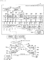
- Fig. 2 is a diagram illustrating an overall configuration example of the power system and a hardware configuration of the voltage and reactive power monitoring/control device according to the first embodiment of the present invention.
- a configuration example of the power system 100 and a hardware configuration example of the voltage and reactive power monitoring/control device 10 are described.
- the configuration example of the power system 100 will be described, and after that, the hardware configuration example of the voltage and reactive power monitoring/control device will be described.
- the power system 100 that is indicated as 100 and illustrated in Fig. 2 mainly illustrates the power transmission system portion, but in the first embodiment of the present invention, this range corresponds to the area where the power system is divided into plural parts.
- the voltage and reactive power monitoring/control device 10 corresponds to the central device that is installed at the local power supply instruction station for monitoring and controlling in the area where the power system is divided into plural parts to perform monitoring and controlling the power system.
- the power system is a concept including a power generation system and a load system in addition to the range indicated as 100. In the following description, the power system is used in a broad sense unless particularly necessary.
- the power system is configured with power supplies 110 (110a and 110b), nodes (buses) 120 (120a, 120b, 120c, 120d, 120e, 120f, 120h, 120i, and 120j), transformers 130 (130a, 130b, 130c, 130d, and 130e), branches (lines) 140 (140b, 140e, 140f, 140g, and 140h), loads 150 (150a 150b, and 150c) and the like as major main circuit constituent equipment, and disposes power condensers (SC: static condenser) 160 (160a, 160b, 160c, and 160d) and shunt reactors (ShR) 170 (170a and 170b) as equipment for power adjustment at appropriate individual locations.
- SC static condenser
- 160a, 160b, 160c, and 160d shunt reactors
- transformers 130c and 130e are tapped transformers 131, and power condenser 160b and shunt reactors 170a and 170b are connected to the tertiary windings, respectively.
- the transformers 130c and 130e are configured with any one or a plurality of pieces of other controllable equipments (battery, rechargeable secondary battery, EV storage battery, flywheel, other phase modifying equipment (static reactive power compensation device SVC (Static Var Compensator), static reactive power generation device SVG (Static C Var Generator), transformer with phase adjuster LPC (Loop Power Controller), and the like).
- various measurement devices 44 are arranged at appropriate individual locations according to respective purposes at various locations of the power system.
- the individual control devices 45 (45a, 45b) for controlling these pieces of equipment are arranged at appropriate individual locations according to the respective purposes.
- the power source 110 includes a distributed type power source such as solar power generation or wind power generation, an inverter interconnection power source connected to the power system via an inverter, and the like besides a rotary type power source such as a thermal power generator, a hydraulic power generator, and a nuclear power generator.
- a distributed type power source such as solar power generation or wind power generation
- an inverter interconnection power source connected to the power system via an inverter, and the like
- a rotary type power source such as a thermal power generator, a hydraulic power generator, and a nuclear power generator.
- the measurement device 44 is a device that measures any one or a plurality of the node voltage V, the branch current I, the active power P, the reactive power Q, the power factor ⁇ , the tap value, on/off information of a switch of a node, a branch, a transformer, a power condenser, a shunt reactor and the like, and the like.
- This is, for example, a meter transformer VT (Voltage Transformer), a meter transformer PT (Potential Transformer), and a meter current transformer CT (Current Transformer), and is Telemeter (TM) or Super Vision SV which has the function of transmitting data including a data measurement location identification ID or a built-in time stamp of the measurement device.
- a device a phase measurement device (phasor measurement unit (PMU), or other measurement instrument that measures power information (phasor information of voltage) attached with absolute time using GPS may be used.
- the measurement device 44 is described as being in the power system 100 but may be installed on a bus or a line connected to the power source 110, the transformer 130, the tapped transformer 131, the load 150, the power condenser 160, the shunt reactor 170, the measurement device 44, and the individual control device 45.
- the power system of Fig. 2 is generally as described above.
- the voltage and reactive power monitoring/control device 10 inputs the reception data 71 from the measurement device 44 of the power system 100 via the communication network 300 and transmits the transmission data 72 to the individual control device 45.
- the data content of the reception data 71 may include other data, basically the data content is the reference bus measurement value data D5. It is intended to achieve the function of the voltage and reactive power monitoring/control device 10 installed in, for example, a local power supply station based on the data measured at the bus defined as the reference bus among the buses in the power system 100.
- the reference bus measurement value data D5 which is the data content of the reception data 71 is any one or a plurality of data of the node voltage V, the branch current I, the power factor ⁇ , the active power P, and the reactive power Q measured by the measurement device 44, is received by the voltage and reactive power monitoring/control device 10 via the communication network 300, and is stored in the internal reference bus measurement value database DB5.
- the reference bus measurement value data D5 may be collected at once by other monitoring devices, and after that, may be stored in the reference bus measurement value database DB5 via the communication network 300.
- the reference bus measurement value data D5 may be stored in the reference bus measurement value database DB5 from the measurement device 44 or other monitoring devices via the communication network 300.
- the reference bus measurement value data D5 may include a unique number for identifying data and a time stamp.
- the other monitoring devices are, for example, a central power supply instruction station, a system stability monitoring server, and the like.
- the hardware configuration of the voltage and reactive power monitoring/control device 10 in Fig. 2 is as follows. Since the voltage and reactive power monitoring/control device 10 is generally configured with a computer device, the voltage and reactive power monitoring/control device 10 is configured with a display unit 11, an input unit 12 such as a keyboard and a mouse, a communication unit 13, a computer or a computing server (CPU: Central Processing Unit) 14, a memory 15, and various databases DB. These are connected to each other by a bus line 43.
- the display unit 11 is configured as, for example, a display device, but a configuration using a printer device, a sound output device, or the like instead of or in addition to the display device may be used.
- the input unit 12 can be configured with at least one of a keyboard switch, a pointing device such as a mouse, a touch panel, a voice instruction device, and the like.
- the communication unit 13 includes a circuit and a communication protocol for connecting to the communication network 300.
- the CPU 14 reads and executes a predetermined computer program from the program database DB15.
- the CPU 14 may be configured with one or a plurality of semiconductor chips or may be configured as a computer device such as a calculation server.
- the memory 15 is configured as, for example, a RAM (Random Access Memory) to store the computer program read from the program database DB15 or to store calculation result data, image data, and the like required for each process .
- the screen data stored in the memory 14 is transmitted to the display unit 11 to be displayed. An example of the screen to be displayed will be described later.
- the database DB is configured with a predicted value database DB1 that stores a predicted value data D1, an distribution necessity determination reference database DB2 that stores a distribution necessity determination reference data D2, a control subject current output value database DB3 that stores a control subject current output value D3, a control subject output upper-lower limit value/increment value database DB4 that stores a control subject output upper-lower limit value/increment value data D4, a reference bus measurement value database DB5 that stores a reference bus measurement value data D5, a reference bus target value database DB6 that stores a reference bus target value data D6, a control subject sensitivity database DB7 that stores a control subject sensitivity data D7, a conversion coefficient database DB8 that stores a conversion coefficient data D8, a control subject changeable period database DB9 that stores a control subject changeable period data D9, a required reactive power calculation result database DB10 that stores a required reactive power calculation result data D10, a reactive power distribution subject selection
- a system measurement data may be collected through other monitoring/control devices or may be input from various measurement devices.
- a data related to system facilities can be received manually or received from the central power supply instruction station or the like.
- each data may be data that has been set in advance and stored in a database.
- data exchange via the bus line 43 is performed with respect to the data including data of an instruction value, a time, and ID.
- Fig. 2 illustrates the hardware configuration of the voltage and reactive power monitoring/control device 10
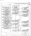
- Fig. 1 describes the voltage and reactive power monitoring/control device 10 with processing functions therein.
- Fig. 1 The processing functions of Fig. 1 are configured by a series of processing units in the calculation unit 41, and shown as process steps in which the data of the result system database DBO are formed from the data of the input system database DBI by a series of processes in the calculation unit 41.
- the databases DB1 to DB14, and DB16 illustrated in Fig. 2 are positioned in either the input system database DBI or the result system database DBO.
- the predicted value database DB1 the distribution necessity determination reference database DB2, the control subject current output value database DB3, the control subject output upper-lower limit value/increment value database DB4, the reference bus measurement value database DB5, the reference bus target value database DB6, the control subject sensitivity database DB7, the conversion coefficient database DB8, and the control subject changeable period database DB9 are positioned.
- the required reactive power calculation result database DB10, the reactive power distribution subject selection result database DB11, the output distribution calculation result database DB12, the control instruction value calculation result database DB13, the control evaluation result database DB14, and the fluctuation component calculation result database DB16 are positioned.
- the calculation unit 41 is configured with a fluctuation component calculation unit 31, a required reactive power calculation unit 32, a reactive power distribution subject selection unit 33, an output distribution calculation unit 34, a control instruction value calculation unit 35, an output instruction unit 36, and a control evaluation unit 37.
- the fluctuation component calculation unit 31 calculates a fluctuation component by using the predicted value data D1 which is the predicted value of the power system information and stores the calculated fluctuation component calculation result data D16 in the fluctuation component calculation result database DB16.
- the required reactive power calculation unit 32 calculates the required reactive power by using the conversion coefficient data D8 of the conversion coefficient database DB8 and the fluctuation component calculation result data D16 calculated by the fluctuation component calculation unit 31 and stores as the required reactive power calculation result data D10 in the required reactive power calculation result database DB10.
- the reactive power distribution subject selection unit 33 selects the reactive power distribution subject by using the control subject changeable period data D9 of the control subject changeable period database DB9, the fluctuation component calculation result data D16 calculated by the required reactive power calculation unit 32, the distribution necessity determination reference data D2 stored in the distribution necessity determination reference database DB2, the control subject current output value data D3 stored in the control subject current output value database DB3, and the control subject output upper-lower limit value/increment value data D4 stored in the control subject output upper-lower limit value/increment value database DB4.
- the selected reactive power distribution subject selection result is accumulated as the reactive power distribution subject selection result data D11 in the reactive power distribution subject selection result database DB11.
- the output distribution calculation unit 34 calculates the output distribution by using the control subject current output value data D3 stored in the control subject current output value database DB3, the control subject output upper-lower limit value/increment value data D4 stored in the control subject output upper-lower limit value/increment value database DB4, the reference bus measurement value data D5 stored in the reference bus measurement value database DB5, the reference bus target value data D6 stored in the reference bus target value database DB6, the control subject sensitivity data D7 stored in the control subject sensitivity database DB7, the calculated required reactive power calculation result data D10, and the calculated reactive power distribution subject selection result data D11 and stores as the output distribution as the output distribution calculation result data D12 in the output distribution calculation result database DB12.
- the control instruction value calculation unit 35 calculates the control instruction value by using the reference bus measurement value data D5 stored in the reference bus measurement value database DB5, the reference bus target value data D6 stored in the reference bus target value database DB6, the control subject sensitivity data D7 stored in the control subject sensitivity database DB7, and the calculated output distribution calculation result data D12 and stores as the control instruction value calculation result data D13 in the control instruction value calculation result database DB13.
- the output instruction unit 36 instructs to output the calculated control instruction value calculation result data D13.
- the control evaluation unit 37 evaluates control by using the calculated fluctuation component calculation result data D16, the calculated required reactive power calculation result data D10, the reactive power distribution subject selection result data D11, the output distribution calculation result data D12, and the control instruction value calculation result data D13.
- the evaluation result is accumulated as control evaluation result data D14 in the control evaluation result database DB14.
- various data accumulated in the databases DB is displayed in an appropriate format either alone or while illustrating correlation.
- the predicted value data D1 the distribution necessity determination reference data D2, the control subject current output value data D3, the control subject output upper-lower limit value/increment value data D4, the reference bus measurement value data D5, the reference bus target value data D6, control subject sensitivity data D7, the calculated required reactive power calculation result data D10, the reactive power distribution subject selection result data D11, the output distribution calculation result data D12, the control instruction value calculation result data D13, and the control evaluation result data D14 is displayed.
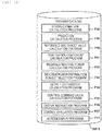
- Fig. 3 exemplifies various programs stored in the program database DB15.
- the program database DB15 stores, for example, a fluctuation component calculation program P31 for realizing function of the fluctuation component calculation unit 31, a required reactive power calculation program P32 for realizing functions of the required reactive power calculation unit 32, a reactive power distribution subject selection program P33 for realizing functions of the reactive power distribution subject selection unit 33, an output distribution calculation program P34 for realizing functions of the output distribution calculation unit 34, a control instruction value calculation program P35 for realizing functions of the control instruction value calculation unit 35, an output instruction program P36 for realizing functions of the output instruction unit 36, a control evaluation program P37 for realizing functions of the control evaluation unit 37, and a screen display program P11 for realizing functions of the display unit 11.
- a fluctuation component calculation program P31 for realizing function of the fluctuation component calculation unit 31
- a required reactive power calculation program P32 for realizing functions of the required reactive power calculation unit 32
- a reactive power distribution subject selection program P33 for realizing
- the CPU 14 executes calculation programs (the fluctuation component calculation program P31, the required reactive power calculation program P32, the reactive power distribution subject selection program P33, the output distribution calculation program P34, the control instruction value calculation program P35, the output instruction program P36, the control evaluation program P37, and the screen display program P11) read from the program database DB15 to the memory 14 to perform the fluctuation component calculation, the required reactive power calculation, the reactive power distribution subject selection, the output distribution calculation, the control instruction value calculation, the output instruction, the control evaluation, the display of various screens, the instruction of an image data to be displayed, the searching for data in various databases, and the like.
- calculation programs the fluctuation component calculation program P31, the required reactive power calculation program P32, the reactive power distribution subject selection program P33, the output distribution calculation program P34, the control instruction value calculation program P35, the output instruction program P36, the control evaluation program P37, and the screen display program P11
- the memory 14 is a memory for temporarily storing the image data for display, the reference bus measurement value data D5, or each calculated temporary data and each calculation result data, and the CPU 14 generates necessary image data and displays the image data on the display unit 11 (for example, display screen).
- the display unit 11 of the voltage and reactive power monitoring/control device 10 may be a simple screen only for rewriting each of the control programs and the databases.
- a plurality of the databases DB are stored in the voltage and reactive power monitoring/control device 10 of the power system.
- the other databases DB DB1 to DB14 and DB16
- the contents of data treated herein will be described more in detail.
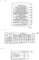
- Fig. 4 illustrates an example of the predicted value data D1 stored in the predicted value database DB1.
- the data of the voltage V, the active power P, the reactive power Q, and the like of each node obtained by the power flow calculation using a power generation plan, a load demand prediction value, and the like are stored as time-series data as the predicted value data D1 in the predicted value database DB1 of Fig. 4 .
- the predicted value data D1 may be acquired by calculation or storage in a separate system such as a monitoring/control device, a central power supply instruction station, or an EMS, may be manually input, or may be calculated with a configuration of a second embodiment described later.
- the data is manually input and stored by the input unit 12.
- necessary image data may be generated and displayed on the display unit 11 by the CPU 14.
- the inputting may be semi-manually performed so that a large amount of data can be set by using a complementary function.
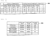
- Fig. 5 illustrates an example of the distribution necessity determination reference data D2 stored in the distribution necessity determination reference database DB2.
- a reference for determining distribution necessity for each fluctuation (fluctuation 1, fluctuation 2, and fluctuation 3) as illustrated in Fig. 5 is stored as distribution necessity determination reference data D2 in the distribution necessity determination reference database DB2.
- the distribution necessity determination reference data D2 may be set remotely from the monitoring/control device, the central power supply instruction station, or the EMS or may be manually input. In manually inputting, the data is manually input and stored by the input unit 12.
- necessary image data may be generated by the CPU 14 and may be displayed on the display unit 11. In inputting, the inputting may be semi-manually performed so that a large amount of data can be set by using a complementary function.
- references for determining distribution necessity for, for example, a short-period fluctuation, a medium-period fluctuation, and a long-period fluctuation are described as the distribution necessity determination reference data D2.
- reference values of the distribution necessity determination reference data D2 are set for, for example, reactive powers ⁇ Q1, ⁇ Q2, and ⁇ Q3 required for suppressing these fluctuations.
- the reference values are set in advance. However, for example, with respect to the reactive power that can be changed to both plus and minus with a constant load fluctuation, if the control is performed to sequentially correspond thereto, unnecessary control is performed. Therefore, a reference value that can be determined to exceed such a fluctuation is set.
- the reference values of such fluctuation data may be corrected by the operator by accumulating the system data or may be automatically corrected.
- Fig. 6 illustrates an example of the control subject current output value data D3 stored in the control subject current output value database DB3.
- the active power P and the reactive power Q of the generator and the reactive power sharing device to be controlled as illustrated in Fig. 6 are stored for each time as the control subject current output value data D3 in the control subject current output value database DB3.
- Fig. 7 illustrates an example of the control subject output upper-lower limit value/increment value data D4 stored in the control subject output upper-lower limit value/increment value database DB4.
- the control subject output upper-lower limit value/increment value database DB4 as the control subject output upper-lower limit value/increment value data D4, as illustrated in Fig. 7 , any one or plural ones of an upper limit value, a lower limit value, and an increment value for each generator and reactive power supply device are configured and stored.
- These data may be stored by using the input unit 12 of the voltage and reactive power monitoring/control device 10 or may be stored from other monitoring devices.
- the reference bus measurement value database DB5 includes the measurement time and the measured value, for example, the voltage V as the reference bus measurement value data D5.
- the measurement device is a VT or the like.
- the reference bus measurement value data D5 may be obtained from the monitoring/control device, the central power supply instruction station, or the EMS or may be directly obtained from the measurement device of the entire system.
- the target value at each time is stored as the reference bus target value data D6 in the reference bus target value database DB6. If a target value is set in a schedule, the target value is stored every period in which the schedule is set. In addition, the value may be set and stored remotely from the monitoring/control device, the central power supply instruction station, or the EMS or may be manually set.
- the reference bus target value is assumed to be calculated and stored in advance in accordance with a method or the like disclosed in " Voltage Stability Maintenance Measures of the Electric Power System, in Technical Report 11-73 of the Institute of Electrical Engineers of Japan, pp. 10-14 (1979 ) ".
- control subject sensitivity database DB7 as the control subject sensitivity data D7, a numerical value indicating how much the change in output of a certain control subject exerts on the bus is stored, and a sensitivity regarding the voltage V and the reactive power Q is stored. These data may be set remotely from the monitoring/control device, the central power supply instruction station, and EMS or may be manually set. In addition, by taking into consideration that the sensitivity varies every moment, these data may be sequentially calculated and stored by the following method.
- control subject sensitivity is a sensitivity matrix and is calculated and stored in advance or sequentially in accordance with a method or the like disclosed in a document by Yokoyama, "Uniform sensitivity coefficient determination method for power system analysis and control", Journal of the Institute of Electrical Engineers of Japan, B, Vol. 94, No. 1, pp. 17 to 24 (1974 ), a document by CONEJO, A., GOMEZ, T., and DE LA FUENTE, J. I., "Pilot-Bus Selection for Secondary Voltage Control", Eur. Trans. Electr. Power Eng., 1993, 3, (5), pp. 359-366 .
- the sensitivity matrix can be obtained by a partial modification of the power flow calculation using the Newton-Raphson method which is often used in the related art.
- the conversion coefficient database DB8 stores conversion coefficients for determining the reactive power required for suppressing these fluctuations. For example, in a case where the fluctuation is a fluctuation in the voltage of the power system, a coefficient for converting to the reactive power required for suppressing this voltage fluctuation is stored as a conversion coefficient. It is preferable that the conversion coefficients are prepared for various types of fluctuations and are prepared for each fluctuation period even though the fluctuation is of the same type.
- the control subject changeable period database DB9 stores response characteristics, adjustment power, and the like for each controllable equipment arranged in the power system.
- the control subject changeable period database DB9 stores information indicating that coping with the fluctuations in a short period is not appropriate due to a mechanical structure but suppressing the fluctuations in a long period is appropriate, information indicating that suppressing the fluctuations in a short period is appropriate due to the configuration with power elements but an adjustment power is limited due to the included capacitor.
- the required reactive power for each fluctuation obtained from the prediction time-series average voltage fluctuation as illustrated in Fig. 9 is stored as the required reactive power calculation result data D10 in the required reactive power calculation result database DB10. Details of Fig. 9 will be described later.
- the selection result of the reactive power distribution subject determined by using the required reactive power calculation result data D10 and the distribution necessity determination reference data D2 is stored as the reactive power distribution subject selection result data D11 in the reactive power distribution subject selection result database DB11.
- This reactive power distribution subject selection result data D11 is included, so that there is an effect that unnecessary distribution to the system status varying every moment can be avoided.
- the calculation result of the output distribution as illustrated in Fig. 10 is stored as the output distribution calculation result data D12 in the output distribution calculation result database DB12. Details of Fig. 10 will be described later.
- the calculation result of the control instruction value obtained from the output distribution calculation result data D12 is stored as the control instruction value calculation result data D13 in the control instruction value calculation database DB13.
- the probability distributions indicating how much the deviation does not occur as a voltage state and a distribution effect, the frequency of use, the number of times of manipulation, and the like of each control device are stored as the control evaluation result data D14 in the control evaluation result database DB14.
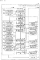
- Fig. 8 is an example of a flowchart illustrating the entire processes of the voltage and reactive power monitoring/control device 10. First, the flow will be described in brief, and then, each component will be described in detail.
- fluctuation component calculation is performed by using the predicted value data D1 which is a predicted value of the power system information.
- the result of the fluctuation component calculation is stored as the fluctuation component calculation result data D16 in the fluctuation component calculation result database DB16.
- required reactive power calculation is performed by using the fluctuation component calculation result data D16 and the conversion coefficient data D8.
- the result of the required reactive power calculation is stored as the required reactive power calculation result data D10 in the required reactive power calculation result database DB2.
- reactive power distribution subject selection is performed by using the control subject changeable period data D9, the distribution necessity determination reference data D2, the control subject current output value data D3, the control subject output upper-lower limit value/increment value data D4, and the calculated required reactive power calculation result data D10.
- the result of the reactive power distribution subject selection is stored as the reactive power distribution subject selection result data D11 in the reactive power distribution subject selection result database DB11.
- output distribution calculation is performed by using the control subject current output value data D3, the control subject output upper-lower limit value/increment value data D4, the reference bus measurement value data D5, the reference bus target value data D6, the control subject sensitivity data D7, the calculated required reactive power calculation result data D10, and the reactive power distribution subject selection result data D11.
- the result of the output distribution calculation is stored as the output distribution calculation result data D12 in the output distribution calculation result database DB12.
- control instruction value calculation is performed by using the reference bus measurement value data D5, the reference bus target value data D6, the control subject sensitivity data D7, and the calculated output distribution calculation result data D12.
- the result of the control instruction value calculation is stored as the control instruction value calculation data D13 in the control instruction value calculation database DB13.
- output instruction is performed by using the calculated control instruction value calculation result data D13.
- control evaluation is performed by using the calculated required reactive power calculation result data D10, the reactive power distribution subject selection result data D11, the output distribution calculation result data D12, the control instruction value calculation result data D13, the fluctuation component calculation result data D16.
- the result of the control evaluation is stored as the control evaluation result data D14 in the control evaluation result database DB14.
- a screen display process step S11 screen display of one or more of the predicted value data D1, the distribution necessity determination reference data D2, the control subject current output value data D3, the control subject output upper-lower limit value/increment value data D4, the reference bus measurement value data D5, the reference bus target value data D6, the control subject sensitivity data D7, the conversion coefficient D8, the control subject changeable period data D9, the calculated required reactive power calculation result data D10, the reactive power distribution subject selection data D11, the output distribution calculation result data D12, the control instruction value calculation result data D13, the control evaluation result data D14, and the fluctuation component calculation result data D16 is performed.
- various calculation results and data accumulated in the memory during the calculation may be sequentially displayed on screens of other monitoring devices.
- the fluctuation component calculation is performed by using the predicted value data D1 which is the predicted value of the power system information, and the result is stored in the fluctuation component calculation result database DB16.
- a waveform of an average voltage Vi is illustrated as the predicted value data D1.
- the waveform of the average voltage Vi illustrates time-series data of the average value of the voltages of the nodes obtained by the power flow calculation using the power generation plan and the load demand prediction value and the like.
- the waveform of the average voltage Vi increases and decreases while fluctuating, and thus, it may be considered that the waveform is formed including a short-period fluctuation, a medium-period fluctuation, and a long-period fluctuation.
- the time-series waveform can be divided into time-series waveforms of respective fluctuation periods by passing the waveform through a preset filter for each fluctuation period of a short period, a medium period, and a long period.
- a fluctuation 1 is a fluctuation component obtained through a filter for a fluctuation period of the short period, and a difference voltage ⁇ V1 is obtained as a difference between a maximum value ⁇ V1max and a minimum value ⁇ V1min in a predetermined time zone of an output of the short-period filter.
- a fluctuation 2 is a fluctuation component obtained through a filter for a fluctuation period of the short period, and a difference voltage ⁇ V2 is obtained as a difference between a maximum value ⁇ V2max and a minimum value ⁇ V2min in a predetermined time zone of an output of the short-period filter.
- a fluctuation 3 is a fluctuation component obtained through a filter for a fluctuation period of the short period and a difference voltage ⁇ V3 is obtained as a difference between a maximum value ⁇ V3max and a minimum value ⁇ V3min in a predetermined time zone of an output of the short-period filter.
- These components are the fluctuation component calculation result data D16.
- the filter for each fluctuation period any processing device that passes a set fluctuation period or removes other than the set fluctuation period such as a high-pass filter, a low-pass filter, or a band pass filter may be used.
- a high-pass filter a low-pass filter
- a band pass filter a processing device that passes a set fluctuation period or removes other than the set fluctuation period
- the filter is configured so that the set fluctuation period of the filter can be adjusted later. With such a configuration, there is an effect that, when a facility changes, the operator can extract the component of the desired fluctuation period corresponding to the facility.
- the required reactive power calculation is performed by using the fluctuation component calculation result data D16 stored in the fluctuation component calculation process step S31, and the result is stored in the required reactive power calculation result database DB10.
- the pre-process of the required reactive power calculation method will be described with reference to Fig. 9 .
- the time-series waveforms of the fluctuation periods are indicated by the fluctuation 1, the fluctuation 2, and the fluctuation 3.
- the fluctuation components having the fluctuation widths of ⁇ V1, ⁇ V2, and ⁇ V3 can be calculated.
- reactive powers ⁇ Q1, ⁇ Q2, and ⁇ Q3 required for suppressing the voltage fluctuation of the differences ⁇ V1, ⁇ V2, and ⁇ V3 can be calculated by using the conversion coefficient data D8 stored in advance.
- the example of the average voltage Vi is illustrated.
- a time-series waveform of the representative voltage may be used, or a time-series of a demand or the like may be used.
- the required reactive power is calculated by performing conversion of each required reactive power. It is preferable that the conversion coefficients are prepared for various types of fluctuations and are prepared for each fluctuation period even though the fluctuation is of the same type.
- the reactive power distribution subject selection is performed by using the control subject changeable period data D9, the distribution necessity determination reference data D2, the control subject current output value D3, the control subject output upper-lower limit/increment value D4, and the required reactive power calculation result data D10 calculated in the power calculation process step S32, and the result is stored in the reactive power distribution subject selection result database DB11.
- the process proceeds to the calculation for selecting the reactive power distribution subject.
- the distribution necessity determination reference database DB2 illustrated in Fig. 5 as the distribution necessity determination reference data D2, the determination references for distribution necessity for the short-period fluctuation 1, the middle-period fluctuation 2, and the long-period fluctuation 3 are described.
- This reference value is set in advance. However, for example, if the reactive power that can be changed both positively and negatively due to a constant load fluctuation is performed sequentially, useless control is performed. For this reason, a reference value that can be determined to exceed the fluctuation is set.
- the reference values of such fluctuation data may be corrected by the operator by accumulating the system data or may be automatically corrected.
- the reactive power distribution subject selection process step S33 by using the control subject current output value data D3 and the control subject output upper-lower limit value/increment value data D4, it is determined whether or not the control subject has the current adjustment power. More specifically, if the current output of the control subject is the upper limit value or a value close thereto, the output can be adjusted in the decreasing direction but cannot be adjusted in the increasing direction, and thus, in a case where the output is required in the increasing and decreasing directions, the output is removed from the subject. On the other hand, in a case where the required reactive power is required in the decreasing direction, since the control subject has an adjustment power, so that the output is allowed to be included in the subject. The same is applied to the increasing direction. If the current output of the control subject is not the upper limit value or a value close thereto, the output is adjustable and is allowed to be included in the subject.
- the corresponding fluctuation is selected from the changeable periods of each control subject by using the control subject changeable period data D9 retained in advance in the control subject changeable period database DB9. Since the response characteristic (changeable period), the adjustment power, and the like are stored in the control subject changeable period database DB9 for each control subject (controllable equipment) arranged in the power system, it is possible to select a controllable equipment which becomes the reactive power distribution subject.
- the output distribution calculation is performed by using the control subject current output value data D3, the control subject output upper-lower limit value/increment value data D4, the reference bus measurement value data D5, the reference bus target value data D6, the control subject sensitivity data D7, the required reactive power calculation result data D10 stored in the fluctuation component calculation process step S31, and the reactive power distribution subject selection result data D11 stored in the reactive power distribution subject selection process step S33, and the result is stored in the output distribution calculation result database DB12.
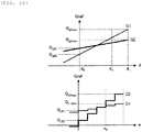
- a distance d is illustrated on the horizontal axis
- a reactive power Q is illustrated on the vertical axis.
- Reactive power output characteristics G1 and G2 of two generators are exemplified.
- the reactive power output characteristics G1 and G2 of the generators can be expressed as straight lines with certain slopes.
- the upper limit of the reactive power output of the generator G1 at the distance d1 is Qglmax
- the upper limit of the reactive power output of the generator G2 is Qg2max
- the reactive power output of the generator G1 at the distance d0 (initial) is Qg01
- the upper limit of the reactive power output of G2 is Qg02.
- the reactive power distribution value that is, the reactive power instruction value Qref is calculated by moving the point dk of an arbitrary distance leftward and rightward.
- the calculation formula of the method of the output distribution calculation will be described later in the control instruction value calculation step S35.
- a distance e is illustrated on the horizontal axis, and a reactive power Q is illustrated on the vertical axis.
- Reactive power output characteristics C1 and C2 of the two reactive power supply devices are exemplified.
- the discrete reactive power supply device is a control subject, but the same effect as that of the upper portion of Fig. 10 can be obtained.
- the discrete reactive power supply device is the control subject, a stepwise waveform is obtained, and thus, there is a need to treat the increment not continuously but discretely.
- the reactive power supply device In the calculation of the reactive power distribution by the reactive power supply device, it is possible to equally distribute the reactive power amount by moving the distance ek leftward and rightward for each increment and performing calculation. In addition, since the distance is moved leftward and rightward for each increment, the number of times of control can be equally distributed, so that there is an effect that it is possible to allow the number of times of manipulation not to be biased to only one facility. With such a configuration, there is an effect that it is possible to prevent maintenance and inspection of the facility from being biased.
- the control of the reactive power supply device is discrete, the discrete values can be approximated and thus, can be treated as a straight line.
- the upper portion and the lower portion of Fig. 10 are diagrams for calculating the output distribution relating to the generator and the reactive power supply device .
- the output distribution is calculated based on the reactive power distribution subject selected in the reactive power distribution subject selection process step S33. Since the values of the generator and the reactive power supply device are different from each other, it is basic not to solve the distribution calculation at the same time. However, in a case where there is a fluctuation that cannot be compensated if both the generator and the reactive power supply device are not used, a preset weight is used, and devising such as correcting the slope of the straight line in Fig. 10 or shifting the maximum value of the distance dk and the maximum value of the distance ek is performed, so that there is an effect that it is possible to calculate the output distribution appropriate for the value considered by the operator.
- the generators that can be treated as continuous values and the discrete reactive power supply devices described above are exemplified as the control subject equipments capable of controlling the reactive power
- representative ones other than the control subject equipments include an LRT, an SC, and an ShR. Since the LRT moves the tap and the SC and the ShR move an on/off device (switch), these devices are forced to be discrete. In these control subject equipments, it is a reason why it is necessary to discretely manipulate a mechanical mechanism unit such as a tap or a switch.
- control instruction value calculation step S35 the control instruction value calculation is performed by using the reference bus measurement value data D5, the reference bus target value data D6, the control subject sensitivity data D7, and the output distribution calculation result data D12 stored at the output distribution calculation process step S34, and the result is stored in the control instruction value calculation database 55.
- the control instruction value can be calculated by solving a quadratic programming method using the output distribution calculated in the output distribution calculation process step S34 and the control subject sensitivity.
- the control instruction value may be performed in accordance with a method disclosed in, for example, a document by A. Conejo, M. J. Aguilar (Secondary voltage control: Nonlinear selection of pilot buses, design of an optimal control law, and simulation results, IEE Proc. -Gener. Transm. Distrib., Vol. 145, No. 1. (1998), pp. 77-81 ), a document by J. L. Sancha, J. L. FernAndez, A. Cortes, and J. T. Abarca (SECONDARY VOLTAGE CONTROL: ANALYSIS, SOLUTIONS AND SIMULATION RESULTS FOR THE SPANISH TRANSMISSION SYSTEM, IEEE, 1995 ) or the like.
- Formula (1) is a quadratic objective function
- Formulas (2) to (5) represent upper and lower limit constraints as linear constraints, respectively.
- ⁇ V P is a voltage deviation of a reference bus
- ⁇ V g is a voltage correction value of a bus of a control subject equipment
- ⁇ Q g is a reactive power deviation of the bus of the control subject equipment
- V ps is a voltage of a critical bus of a non-control subject equipment
- C v is a sensitivity matrix relating to a voltage value increment of the control subject equipment and a voltage value increment of the reference bus
- C vs is a sensitivity matrix relating to a voltage value increment of the control subject equipment and a voltage value increment of a bus of a load not selected as the reference bus
- C q is a sensitivity matrix relating to a voltage value increment of the control subject equipment and an applied reactive power increment of the control subject equipment
- ⁇ is a parameter for determining a closed loop time constant
- m is a weight parameter for determining relative importance of two constituent elements of the objective function
- V g max , Q g max , and V ps max
- Formula (1) includes two elements. The first one is an element minimizing the deviation of the reference bus voltage, and the second one is an element minimizing the deviation of the reactive power between the control subject equipments from the target value.
- Formulas (2) to (5) are the upper and lower limit constraints.
- Each sensitivity matrix corresponds to the control subject sensitivity data and is given by the control subject sensitivity database DB7. With such a configuration, the voltage deviation from the reference bus target value is minimized, and the deviation of the target reactive power determined by the reactive power output distribution on the generators included in the preset zones is minimized.
- the generators included in the zones are allowed to reach the limit of the reactive power output at the same time.
- the reactive power can be equally distributed according to capacity, it is possible to prevent such phenomena that some of the generators first reach the reactive power limit and the voltage stability is extremely deteriorated, and thus, it is possible to improve supply reliability.
- the calculation of the reactive power distribution described above in the output distribution calculation process step S34 is supplemented.
- the reactive power target value Qref is illustrated on the vertical axis and the distance d is illustrated on the horizontal axis
- the reactive power output characteristic of the generator becomes a straight line having a certain slope.
- Qglmax and Qg2max are the reactive power upper limit constraints of the generators G1 and G2
- Qg01 and Qg02 are initial reference values of the reactive power of the generators G1 and G2 and are values received from the voltage and reactive power monitoring/control device or set in advance.
- d is a free variable of optimization problem.
- ⁇ Q gi is the reactive power deviation of the control subject equipment i
- ⁇ Qg 0i is the initial reference value of the reactive power of the control subject equipment i
- k i is the set slope of the control subject equipment i
- the adjustment of the reactive power depends on the reference
- Q gi is the instantaneous reactive power value of the control subject equipment i.
- the reference bus may be set by using the method of selecting a reference bus or the like disclosed in these documents or the like, or the reference bus may be set in advance.
- the reference bus may be set according to the knowledge in the related art or may be set again by using the method of the above-described document.
- the number of reference buses may be decreased or may be increased. With such a configuration, it is possible to set the reference bus appropriately for the current observation point.
- the output distribution and the output instruction can be performed for any fluctuation component, and thus, even though the output fluctuation of the renewable energy or the change of the power source configuration or the system configuration occurs due to the weather along with the elapse of time, it is possible to maintain the balance between the voltage and the reactive power of the power system, and it is possible to improve economic efficiency.
- the output instruction is performed by using the control instruction value calculation result data D13 stored in the control instruction value calculation process step S35.
- the transmission destination is, for example, an individual control device 45 for maintaining balance between the voltage and the reactive power in a certain area, and the individual control device 45 receives one or more of the control instruction value calculation result data D13 at a preset period and performs the voltage and reactive power control.
- control evaluation process step S37 in order to easily check whether or not the operator correctly follows the target value as the calculation of the control evaluation performed by using the required reactive power calculation result data D10 stored in the required reactive power calculation process step S32, the reactive power distribution subject selection result data D11 stored in the reactive power distribution subject selection process step S33, the output distribution calculation result data D12 stored in the output distribution calculation process step S34, and the control instruction value calculation result data D13 stored in the control instruction value calculation process step S35, a deviation between the target voltage and the measured value is calculated, and the result is stored in the control evaluation result database 56.
- the display example of the screen 90 illustrated in Fig. 11 is an example of a visualized display of the operation state of the power system monitored and controlled by the voltage and reactive power monitoring/control device 10.
- the state such as the time of acquisition is displayed on a small screen 91.
- the voltage as the measured value at the node (the bus 1 in the example of the figure) selected by the tab together with various constraint conditions (upper limit value of the operation voltage, target voltage width, target voltage) and a current operating point is visualized and displayed on a small screen 92 in a time-series manner.
- the probability density is displayed on a small screen 93 for each fluctuation element selected by the tab.
- the number of times of manipulation of each reactive power supply device is compared and displayed on a small screen 94 for the reason of managing a degree of deterioration of the plurality of reactive power supply devices.
- display of the distribution level of the reactive power Q illustrated in Figs. 9 and 10 display of the distribution effect by the distribution, display of the extent of deviation in the case of the probability distribution, display of the frequency of use and the number of times of manipulation of each control device, or a display to clearly indicate what kind of countermeasure is necessary in which band as a screen also displaying a trend, display of a countermeasure equipment in this case, display of insufficient capacity, and the like are also performed.
- the target selection result data D11, the output distribution calculation result data D12 stored in the output distribution calculation process step S34, the control instruction value calculation result data D13 stored in the control instruction value calculation process step S35, and the control evaluation result data D14 stored in the control evaluation process step S37 is performed.
- the probability distribution indicating how much the deviation does not occur as a voltage state or a distribution effect, the frequency of use, the number of times of manipulation, and the like of each control device are stored.
- the present invention discloses the system configuration including the central device for monitoring and controlling the power system and the individual control device installed at an individual location of the power system and operated by the transmission data from the central device, it is considered that the central device in the second embodiment described with reference to Figs. 12 to 15 cooperates with the central power supply instruction station that performs monitoring and controlling the entire power system or is installed in the central power supply instruction station to perform intra-area control.
- the voltage and reactive power monitoring/control device 10 which is the central device of the second embodiment, treats the data possessed by the central power supply instruction station, and the data obtained from the power system are also more various.
- the second embodiment since one or more calculation units for the predicted value data D1 and the reference bus target value data D6 according to the first embodiment are provided, the second embodiment is different from the first embodiment in terms of the input data, the configuration, the program, and the control flow.
- the first embodiment even if it becomes impossible to receive the predicted value data D1 and the reference bus target value data D6 from the other device, it is possible to provide one or both of the effects of maintaining balance between the voltage and the reactive power and improving the economic efficiency in the power system by only the voltage and reactive power monitoring/control device 10.
- the voltage and reactive power monitoring/control device according to the second embodiment will be described. However, descriptions of the same operations at the same components as those of the first embodiment will be omitted.
- Fig. 13 is a diagram illustrating an overall configuration example of the power system and a hardware configuration of the voltage and reactive power monitoring/control device according to the second embodiment of the present invention.
- the overall configuration of the power system of Fig. 13 is basically the same as the overall configuration of the power system of Fig. 2 .
- the data transmitted from the power system to the voltage and reactive power monitoring/control device 10 newly includes the system measurement data D17 in addition to the reference bus measurement value data D5.
- the system measurement data D17 is a measurement data at an arbitrary location of the power system and is a measurement data in a wider range and broad sense, which also includes the reference bus measurement value data D5 which is data measured with the reference bus.
- the measurement data of the reference bus can be estimated from the system measurement data D17.
- the power system to be monitored and controlled may be the entire power system or any of the segmented areas.
- two new databases DB are additionally provided. These are a system measurement database DB17 and a system facility database DB18 positioned in the input side database DBI of Fig. 1 .
- Fig. 12 is a diagram in which the voltage and reactive power monitoring/control device 10 is described by the processing functions therein and corresponds to Fig. 1 of the first embodiment.
- the different point in configuration is that, as the processing functions, a status estimation calculation unit 38, a predicted value calculation unit 39, and a reference bus target value calculation unit 40 are added to the calculation unit 41.
- the input side database DBI of Fig. 12 includes the system measurement database DB17 and the system facility database DB18.
- the results of the predicted value calculation unit 39 and the reference bus target value calculation unit 40 are input data of the subsequent process, the results are stored in the input side database DBI. However, in some cases, the results may also be referred to as a result side database DBO.
- Fig. 14 is a diagram illustrating a program configuration corresponding to Fig. 3 , and a different point in configuration is that a status estimation calculation program P38, a predicted value calculation program P39, and a reference bus target value calculation program P40 are added in the program database DB15.
- the system measurement data D17 will be described.
- the reference bus measurement value data D5 is positioned as the data measured at the reference bus, but the system measurement data D17 may be regarded as a wider-range measurement data without specifying the measurement position.
- the system measurement data D17 of Fig. 13 and the like is data of any one or a plurality of a node voltage V, a branch current I, a power factor ⁇ , an active power P, and a reactive power Q measured by the measurement device 44 and is received via the communication network 300 and stored in the system measurement database DB17.
- the system data may be collected at once by other monitoring devices and, after that, may be stored in the system measurement database DB17 via the communication network 300.
- the system data may be stored in the system measurement database DB17 from the measurement device 44 or other monitoring devices via the communication network 300.
- the system measurement data D17 may include a unique number for identifying data and a time stamp.
- the other monitoring devices are, for example, a central power supply instruction station, a system stability monitoring server, and the like.
- system facility data D18 A system configuration, a line impedance (R + jX), a ground capacitance (admittance: Y), a power source data, and the like are included and stored as the system facility data D18 in the system facility database DB18 of Fig. 13 and the like.
- the system configuration includes connection relations of one or a plurality of the bus, the transmission line, the power source, the load, the transformer of the system and the respective control devices.
- the system facility data D18 may be obtained from the monitoring/control device, the central power supply instruction station, or the EMS or may be manually input. In manually inputting, the data is manually input and stored by the input unit 12.
- necessary image data may be generated by the CPU 14 and may be displayed on the display unit 11. In inputting, the inputting may be semi-manually performed so that a large amount of data can be set by using a complementary function.
- Fig. 15 is an example of a flowchart illustrating the entire processes of the power system voltage and reactive power monitoring/control device 10, the portions where the calculation is added will be described.
- the system status at the time of the system measurement is calculated by the calculation of the status estimation calculation program P38 added to Fig. 14 by using the system measurement data D17, the system facility data D18, and appropriately set calculation setting data, and the status estimation calculation result is stored.
- the status estimation calculation result may be stored at an appropriate location in the storage device.
- a status estimation calculation result database may be provided as a dedicated database.
- the status estimation calculation by the status estimation calculation program P38 is a calculation function of determining whether or not an abnormal data exists in an observation data and eliminating the abnormal data based on the observation data and the connection data of substations, power plants, and a power transmission/distribution equipment starting from a transmission line and estimating a likely system status at a specific time cross-section.
- the status estimation calculation may be performed in accordance with various methods disclosed in, for example, a document by Lars Holten, Anders Gjelsvlk, Sverre Adam, F. F. Wu, and Wen-Hs lung E. Liu, "Comparison of Different Methods for Status estimation", IEEE Transaction on Power Systems, Vol. 3 (1988), pp. 1798-1806 .
- the prediction calculation of the future system status from the time of the system measurement is performed by the predicted value calculation program P39 by using the status estimation calculation result data, the total demand prediction result data, the generator fuel consumption characteristic data, the data of the ratio of the substation load to the total demand, and the substation load PQ correlation data, and the system status is stored in the predicted value database DB1.
- the total demand prediction result data may be calculated in accordance with a demand prediction method disclosed in a document by Ryoichi Hara, "Analysis and prediction technique of time-series data related to supply and demand operation of power system", Journal of the Institute of Electrical Engineers of Japan, B, Vol. 134, No. 4, 2014, pp.
- the total demand prediction result data to be performed at the central power supply instruction station may be periodically obtained via the communication network 300 or may be set in advance.
- the voltage and reactive power monitoring/control device 10 which is the central device, cooperates with a central power supply instruction station which performs monitoring and controlling the entire power system or is installed at the central power supply instruction station to perform intra-area control.
- the data to be mainly used in the status estimation calculation process step S38 and the predicted value calculation process step S39 can be obtained by cooperation with the central power supply instruction station.
- the predicted value calculation in the predicted value calculation process step S39 can be performed in accordance with, for example, a method disclosed by Takahiro Ishida, et al., "Predictive Preceding Voltage and Reactive Power Control Scheme to Key System Using LP Method", Electrotechnical Theory B, Vol. 117, No. 8, 1997, pp. 1116-1120 .
- the generator active power output of each generator is predicted and calculated from the total demand prediction result data and the generator fuel consumption characteristic data by using ELD (economic load distribution).
- the substation individual active power load is predicted and calculated from the total demand prediction result data and the data of the ratio of the substation load to the total demand by using Formula (7).
- P li is the prediction result of the active power load of the substation i
- P all is the prediction result of the total demand
- ratio i is the ratio of the active power load of the substation i to the total demand.
- the substation individual reactive power load is estimated and calculated from the prediction result of the substation individual active power load and the substation load PQ correlation data by using Formula (8).
- Q li is the prediction result of the reactive power load of the substation i
- f i is the PQ correlation of the substation i.
- the power flow state in the future time cross-section from the prediction result of the generator active power output, the prediction result of the substation individual active power load, and the prediction result of the substation individual reactive power load by using an AC power flow calculation method.
- the AC power flow calculation method can be performed in accordance with, for example, a method disclosed by William F Tinney and Clifford E Hart, Power Flow Solution by Newton's Method, IEEE Transaction on Power Apparatus and Systems, Vol. PAS-86, No. 11 (1967) pp. 1449-1967 .
- the reference bus target value calculation is performed by using the predicted value data D1, the status estimation result data, and the system facility data D18.
- the reference bus target value may be calculated in an offline manner in accordance with a method or the like disclosed in Voltage Stability Maintenance Measures of the Electric Power System, in "Technical Report 11-73 of the Institute of Electrical Engineers of Japan, pp. 10-14 (1979 ) or may be calculated in accordance with a method or the like disclosed in a document by Junki Someya et al., "Study of optimum control of reference voltage by interior point method in East Japan power system", 2003, National Convention of the Institute of Electrical Engineers of Japan, 6-159, pp. 273-274 .
- the output distribution and the output instruction can be performed for any fluctuation component, so that it is possible to maintain the balance between the voltage and the reactive power of the power system, and it is possible to improve economic efficiency.
- a third embodiment as the contents of the control evaluation in step S37 performed by the control evaluation unit 37 in the first or second embodiment, an example of a screen of a trend display of the required reactive power, the future prediction, the current/past reactive power equipment capacity, and the future required equipment capacity is additionally illustrated.
- the equipment configuration and the evaluation flow are the same as those in the first embodiment or the second embodiment.
- the display example of the screen 90 illustrated in Fig. 16 is an example of display of visualization of the evaluation result of the voltage and reactive power monitoring/control device 10.
- the small screen 95 with respect to the evaluation result calculation content, the insufficient amount of the reactive power at the prediction time and the proposal 1 that the generator G4 should be additionally used as a countermeasure therefor are displayed.
- the small screen 96 with respect to the fluctuation selected on the tab, the required reactive power ⁇ Q is displayed together with the past value, the predicted value, the equipment capacity, and the required equipment capacity along with the elapse of time.
- the magnitudes of the equipment capacity and the required equipment capacity are displayed. Therefore, there is an effect that it is easier for an operator to grasp the trend, and thus, it is easier to make a decision.
Landscapes
- Engineering & Computer Science (AREA)
- Power Engineering (AREA)
- General Engineering & Computer Science (AREA)
- Physics & Mathematics (AREA)
- General Physics & Mathematics (AREA)
- Automation & Control Theory (AREA)
- Supply And Distribution Of Alternating Current (AREA)
- Remote Monitoring And Control Of Power-Distribution Networks (AREA)
Applications Claiming Priority (2)
| Application Number | Priority Date | Filing Date | Title |
|---|---|---|---|
| JP2016121478A JP6933450B2 (ja) | 2016-06-20 | 2016-06-20 | 電圧無効電力監視制御装置及び方法 |
| PCT/JP2017/011175 WO2017221483A1 (ja) | 2016-06-20 | 2017-03-21 | 電圧無効電力監視制御装置及び方法 |
Publications (2)
| Publication Number | Publication Date |
|---|---|
| EP3474408A1 true EP3474408A1 (de) | 2019-04-24 |
| EP3474408A4 EP3474408A4 (de) | 2020-02-19 |
Family
ID=60783346
Family Applications (1)
| Application Number | Title | Priority Date | Filing Date |
|---|---|---|---|
| EP17814955.5A Withdrawn EP3474408A4 (de) | 2016-06-20 | 2017-03-21 | Vorrichtung und verfahren zur überwachung von spannung und blindleistung |
Country Status (4)
| Country | Link |
|---|---|
| US (1) | US10892640B2 (de) |
| EP (1) | EP3474408A4 (de) |
| JP (1) | JP6933450B2 (de) |
| WO (1) | WO2017221483A1 (de) |
Cited By (1)
| Publication number | Priority date | Publication date | Assignee | Title |
|---|---|---|---|---|
| EP4492604A4 (de) * | 2022-03-09 | 2026-03-04 | Hitachi Ltd | System zur berechnung der auflösung von systemverletzungen, systemverletzungen, fehlerberechnungssystem, systemstabilisierungssystem |
Families Citing this family (26)
| Publication number | Priority date | Publication date | Assignee | Title |
|---|---|---|---|---|
| ES2873227T3 (es) * | 2016-03-04 | 2021-11-03 | Toshiba Kk | Dispositivo de control de potencia reactiva de tensión y programa de control de potencia reactiva de tensión |
| JP6876406B2 (ja) * | 2016-10-20 | 2021-05-26 | 株式会社日立製作所 | 電圧無効電力運用支援装置および支援方法、並びに電圧無効電力運用監視制御装置および監視制御方法 |
| WO2018177529A1 (en) * | 2017-03-30 | 2018-10-04 | Universita' Della Svizzera Italiana | Method to accelerate the processing of multiperiod optimal power flow problems |
| US10985573B2 (en) * | 2017-09-11 | 2021-04-20 | Toshiba Mitsubishi-Electric Industrial Systems Corporation | Power generation system |
| JP7115169B2 (ja) * | 2018-04-03 | 2022-08-09 | 富士電機株式会社 | 電力系統の監視制御システム、及び、無効電力補償装置の制御定数設定支援システム |
| US11297103B2 (en) | 2018-04-30 | 2022-04-05 | Battelle Memorial Institute | High-fidelity model-driven deception platform for cyber-physical systems |
| US11387651B2 (en) * | 2019-05-26 | 2022-07-12 | Battelle Memorial Institute | Coordinated voltage control and reactive power regulation between transmission and distribution systems |
| EP3996267A4 (de) * | 2019-07-02 | 2023-03-22 | Toshiba Mitsubishi-Electric Industrial Systems Corporation | Stromumwandlungsvorrichtung und stromumwandlungssystem |
| CN110247405B (zh) * | 2019-07-18 | 2021-10-29 | 阳光电源股份有限公司 | 一种无功调度控制方法、系统及数据处理模块 |
| US11404907B2 (en) * | 2019-11-25 | 2022-08-02 | Hitachi Energy Switzerland Ag | Distributed voltage control for power networks |
| JP7254041B2 (ja) * | 2020-02-21 | 2023-04-07 | 株式会社日立製作所 | 系統計画支援システムおよび系統計画支援方法 |
| CN111654112B (zh) * | 2020-06-17 | 2022-04-29 | 新奥数能科技有限公司 | 一种无功补偿电容器预警方法、装置及系统 |
| US11695299B2 (en) * | 2020-10-01 | 2023-07-04 | Tianjin University | Quick-response voltage control method of distribution system considering multiple participants |
| CN112909959B (zh) * | 2021-01-20 | 2022-11-01 | 广东电网有限责任公司 | 一种无功优化方法、装置、设备及存储介质 |
| CN112838622B (zh) * | 2021-03-26 | 2023-07-14 | 云南电网有限责任公司电力科学研究院 | 一种10kV供电区域的无功电压优化控制方法及系统 |
| US11522478B2 (en) | 2021-05-05 | 2022-12-06 | Cummins Power Generation Inc. | Systems and methods for predictive load response |
| CN113641468B (zh) * | 2021-06-23 | 2023-09-22 | 河北中兴冀能电力发展有限公司 | 一种应用于电力仪器设备的板间多运算芯片算力平衡系统 |
| CN114123230B (zh) * | 2021-12-06 | 2022-09-30 | 湘潭大学 | 风储联合多目标无功优化方法 |
| JP2023165290A (ja) * | 2022-05-02 | 2023-11-15 | 株式会社日立製作所 | 保守計画支援装置、保守計画支援システム、及び保守計画支援方法 |
| CN115459299B (zh) * | 2022-10-11 | 2024-06-25 | 南方电网数字电网研究院有限公司 | 低压配电无功调节方法、装置、计算机设备和存储介质 |
| JP7754788B2 (ja) * | 2022-10-24 | 2025-10-15 | 株式会社日立製作所 | 将来断面作成システム、将来断面作成方法 |
| CN116754901B (zh) * | 2023-08-21 | 2023-11-03 | 安徽博诺思信息科技有限公司 | 一种基于快速定位的配电网故障分析管理平台 |
| CN116845886B (zh) * | 2023-08-29 | 2023-12-05 | 华能江苏综合能源服务有限公司 | 一种基于模型预测的多端口自主光伏系统构网型控制方法 |
| CN117526443B (zh) * | 2023-11-07 | 2024-04-26 | 北京清电科技有限公司 | 一种基于电力系统的配电网优化调控方法及系统 |
| CN121192733B (zh) * | 2025-11-20 | 2026-04-17 | 内蒙古电力(集团)有限责任公司乌海超高压供电分公司 | 一种无功补偿设备的电压调节系统 |
| CN121417259B (zh) * | 2025-12-23 | 2026-03-31 | 湖南大学 | Svg多工况控制参数优化方法及系统 |
Family Cites Families (17)
| Publication number | Priority date | Publication date | Assignee | Title |
|---|---|---|---|---|
| JPH07288932A (ja) | 1994-04-14 | 1995-10-31 | Toshiba Corp | 電圧無効電力制御における協調制御方法 |
| JPH08149895A (ja) * | 1994-11-17 | 1996-06-07 | Toshiba Corp | 負荷転流型インバータ起動発電システム |
| JP3355857B2 (ja) * | 1995-04-04 | 2002-12-09 | 株式会社日立製作所 | 電圧無効電力制御装置 |
| JP3108054B2 (ja) * | 1998-06-15 | 2000-11-13 | 沖縄電力株式会社 | インバータの制御方法 |
| JP3792428B2 (ja) * | 1999-03-09 | 2006-07-05 | 三菱電機株式会社 | 電力系統制御装置及び電力系統制御方法 |
| JP2000341860A (ja) * | 1999-05-24 | 2000-12-08 | Nissin Electric Co Ltd | 電力貯蔵装置 |
| JP3952355B2 (ja) * | 2000-12-28 | 2007-08-01 | 東京電力株式会社 | 配電系統の監視方法 |
| JP3815235B2 (ja) * | 2001-03-05 | 2006-08-30 | 株式会社明電舎 | 受電設備 |
| JP4058279B2 (ja) | 2002-03-04 | 2008-03-05 | 株式会社東芝 | 電圧無効電力監視制御装置及び電圧無効電力監視制御プログラム |
| EP1744058A1 (de) * | 2004-05-07 | 2007-01-17 | Mitsubishi Denki Kabushiki Kaisha | Windkraftwerkbeurteilungssystem und vorhersagesteuerdienstsystem für windkraftwerk |
| JP5984601B2 (ja) * | 2012-09-21 | 2016-09-06 | 株式会社日立製作所 | 系統制御装置および系統制御方法 |
| US9667100B2 (en) * | 2013-06-26 | 2017-05-30 | Mitsubishi Electric Corporation | Voltage monitoring control device and voltage monitoring control method |
| JP2015073411A (ja) * | 2013-10-04 | 2015-04-16 | 株式会社東芝 | 電圧制御システム |
| US10135247B2 (en) | 2013-10-17 | 2018-11-20 | General Electric Company | Methods and systems for integrated Volt/VAr control in electric network |
| JP6478588B2 (ja) * | 2014-11-26 | 2019-03-06 | 三菱電機株式会社 | 電圧制御装置および電圧計測装置 |
| JP6412822B2 (ja) * | 2015-04-22 | 2018-10-24 | 株式会社日立製作所 | 電力系統電圧無効電力監視制御装置及び方法 |
| JP5933857B1 (ja) * | 2015-05-27 | 2016-06-15 | 三菱電機株式会社 | 電圧制御装置および電圧計測装置 |
-
2016
- 2016-06-20 JP JP2016121478A patent/JP6933450B2/ja active Active
-
2017
- 2017-03-21 US US16/099,448 patent/US10892640B2/en not_active Expired - Fee Related
- 2017-03-21 WO PCT/JP2017/011175 patent/WO2017221483A1/ja not_active Ceased
- 2017-03-21 EP EP17814955.5A patent/EP3474408A4/de not_active Withdrawn
Cited By (1)
| Publication number | Priority date | Publication date | Assignee | Title |
|---|---|---|---|---|
| EP4492604A4 (de) * | 2022-03-09 | 2026-03-04 | Hitachi Ltd | System zur berechnung der auflösung von systemverletzungen, systemverletzungen, fehlerberechnungssystem, systemstabilisierungssystem |
Also Published As
| Publication number | Publication date |
|---|---|
| EP3474408A4 (de) | 2020-02-19 |
| JP6933450B2 (ja) | 2021-09-08 |
| US10892640B2 (en) | 2021-01-12 |
| US20190148977A1 (en) | 2019-05-16 |
| JP2017229110A (ja) | 2017-12-28 |
| WO2017221483A1 (ja) | 2017-12-28 |
Similar Documents
| Publication | Publication Date | Title |
|---|---|---|
| US10892640B2 (en) | Voltage and reactive power monitoring/control device and method for calculating required reactive power amount for suppressing a fluctuation component and selecting an appropriate equipment | |
| JP6876406B2 (ja) | 電圧無効電力運用支援装置および支援方法、並びに電圧無効電力運用監視制御装置および監視制御方法 | |
| JP6412822B2 (ja) | 電力系統電圧無効電力監視制御装置及び方法 | |
| Hashim et al. | A review on voltage control methods for active distribution networks | |
| JP6239754B2 (ja) | 電圧安定度監視装置および方法 | |
| EP2506383B1 (de) | System und Verfahren zum Betrieb von Kondensatorbänken | |
| US20170017298A1 (en) | Real time control of voltage stability of power systems at the transmission level | |
| Alhelou et al. | Decision-making-based optimal generation-side secondary-reserve scheduling and optimal LFC in deregulated interconnected power system | |
| US20170353033A1 (en) | Power system stabilization device and method | |
| Bedawy et al. | An effective coordination strategy for voltage regulation in distribution system containing high intermittent photovoltaic penetrations | |
| Momoh et al. | Review of optimization techniques for renewable energy resources | |
| WO2016063660A1 (ja) | 電力系統監視装置および電力系統監視方法 | |
| JPH11146560A (ja) | 疎結合電力系統制御装置 | |
| Petintin et al. | Voltage regulation in a smart distribution system incorporating variable renewable generation | |
| JP5415478B2 (ja) | 電圧制御システム | |
| Sharma | Renewable energy systems with improved power quality in smart grid using fuzzy logic method | |
| Zima et al. | On multi-area control in electric power systems | |
| JP2022127758A (ja) | 整定値計算装置および方法 | |
| Yang et al. | An adaptive control for supporting village power grid integrating residential PV power generation | |
| Smajkić et al. | Design and implementation of voltage VAR control in closed loop mode: benefits and pitfalls | |
| Ibrahim | Voltage security optimization for power transmission systems | |
| Hirodontis et al. | LOAD SHEDDING SCHEMES FOR ISLANDING DISTRIBUTION NETWORK OPERATION | |
| Attar et al. | Investigation of The Impacts of Primary Substation's Oltc on Voltage Regulators Placement in Distribution Systems | |
| Ibrahim | Distribution system optimization with integrated distributed generation | |
| Mustafa | DER Utilization for Voltage-Sag Mitigation by Applying Different Network Partitioning Techniques |
Legal Events
| Date | Code | Title | Description |
|---|---|---|---|
| STAA | Information on the status of an ep patent application or granted ep patent |
Free format text: STATUS: THE INTERNATIONAL PUBLICATION HAS BEEN MADE |
|
| PUAI | Public reference made under article 153(3) epc to a published international application that has entered the european phase |
Free format text: ORIGINAL CODE: 0009012 |
|
| STAA | Information on the status of an ep patent application or granted ep patent |
Free format text: STATUS: REQUEST FOR EXAMINATION WAS MADE |
|
| 17P | Request for examination filed |
Effective date: 20190121 |
|
| AK | Designated contracting states |
Kind code of ref document: A1 Designated state(s): AL AT BE BG CH CY CZ DE DK EE ES FI FR GB GR HR HU IE IS IT LI LT LU LV MC MK MT NL NO PL PT RO RS SE SI SK SM TR |
|
| AX | Request for extension of the european patent |
Extension state: BA ME |
|
| DAV | Request for validation of the european patent (deleted) | ||
| DAX | Request for extension of the european patent (deleted) | ||
| A4 | Supplementary search report drawn up and despatched |
Effective date: 20200121 |
|
| RIC1 | Information provided on ipc code assigned before grant |
Ipc: H02J 3/00 20060101AFI20200115BHEP Ipc: H02J 3/16 20060101ALI20200115BHEP Ipc: H02J 13/00 20060101ALI20200115BHEP |
|
| STAA | Information on the status of an ep patent application or granted ep patent |
Free format text: STATUS: EXAMINATION IS IN PROGRESS |
|
| 17Q | First examination report despatched |
Effective date: 20200806 |
|
| STAA | Information on the status of an ep patent application or granted ep patent |
Free format text: STATUS: THE APPLICATION HAS BEEN WITHDRAWN |
|
| 18W | Application withdrawn |
Effective date: 20200904 |