EP3475574B1 - Trockenlaufende flügelzellen-gaspumpe - Google Patents
Trockenlaufende flügelzellen-gaspumpe Download PDFInfo
- Publication number
- EP3475574B1 EP3475574B1 EP17713583.7A EP17713583A EP3475574B1 EP 3475574 B1 EP3475574 B1 EP 3475574B1 EP 17713583 A EP17713583 A EP 17713583A EP 3475574 B1 EP3475574 B1 EP 3475574B1
- Authority
- EP
- European Patent Office
- Prior art keywords
- fluid outlet
- pump
- dry
- outlet opening
- gas pump
- Prior art date
- Legal status (The legal status is an assumption and is not a legal conclusion. Google has not performed a legal analysis and makes no representation as to the accuracy of the status listed.)
- Active
Links
Images

Classifications
-
- F—MECHANICAL ENGINEERING; LIGHTING; HEATING; WEAPONS; BLASTING
- F04—POSITIVE - DISPLACEMENT MACHINES FOR LIQUIDS; PUMPS FOR LIQUIDS OR ELASTIC FLUIDS
- F04C—ROTARY-PISTON, OR OSCILLATING-PISTON, POSITIVE-DISPLACEMENT MACHINES FOR LIQUIDS; ROTARY-PISTON, OR OSCILLATING-PISTON, POSITIVE-DISPLACEMENT PUMPS
- F04C29/00—Component parts, details or accessories of pumps or pumping installations, not provided for in groups F04C18/00 - F04C28/00
- F04C29/12—Arrangements for admission or discharge of the working fluid, e.g. constructional features of the inlet or outlet
-
- F—MECHANICAL ENGINEERING; LIGHTING; HEATING; WEAPONS; BLASTING
- F04—POSITIVE - DISPLACEMENT MACHINES FOR LIQUIDS; PUMPS FOR LIQUIDS OR ELASTIC FLUIDS
- F04C—ROTARY-PISTON, OR OSCILLATING-PISTON, POSITIVE-DISPLACEMENT MACHINES FOR LIQUIDS; ROTARY-PISTON, OR OSCILLATING-PISTON, POSITIVE-DISPLACEMENT PUMPS
- F04C18/00—Rotary-piston pumps specially adapted for elastic fluids
- F04C18/30—Rotary-piston pumps specially adapted for elastic fluids having the characteristics covered by two or more of groups F04C18/02, F04C18/08, F04C18/22, F04C18/24, F04C18/48, or having the characteristics covered by one of these groups together with some other type of movement between co-operating members
- F04C18/34—Rotary-piston pumps specially adapted for elastic fluids having the characteristics covered by two or more of groups F04C18/02, F04C18/08, F04C18/22, F04C18/24, F04C18/48, or having the characteristics covered by one of these groups together with some other type of movement between co-operating members having the movement defined in group F04C18/08 or F04C18/22 and relative reciprocation between the co-operating members
- F04C18/344—Rotary-piston pumps specially adapted for elastic fluids having the characteristics covered by two or more of groups F04C18/02, F04C18/08, F04C18/22, F04C18/24, F04C18/48, or having the characteristics covered by one of these groups together with some other type of movement between co-operating members having the movement defined in group F04C18/08 or F04C18/22 and relative reciprocation between the co-operating members with vanes reciprocating with respect to the inner member
-
- F—MECHANICAL ENGINEERING; LIGHTING; HEATING; WEAPONS; BLASTING
- F04—POSITIVE - DISPLACEMENT MACHINES FOR LIQUIDS; PUMPS FOR LIQUIDS OR ELASTIC FLUIDS
- F04C—ROTARY-PISTON, OR OSCILLATING-PISTON, POSITIVE-DISPLACEMENT MACHINES FOR LIQUIDS; ROTARY-PISTON, OR OSCILLATING-PISTON, POSITIVE-DISPLACEMENT PUMPS
- F04C25/00—Adaptations of pumps for special use of pumps for elastic fluids
- F04C25/02—Adaptations of pumps for special use of pumps for elastic fluids for producing high vacuum
-
- F—MECHANICAL ENGINEERING; LIGHTING; HEATING; WEAPONS; BLASTING
- F04—POSITIVE - DISPLACEMENT MACHINES FOR LIQUIDS; PUMPS FOR LIQUIDS OR ELASTIC FLUIDS
- F04C—ROTARY-PISTON, OR OSCILLATING-PISTON, POSITIVE-DISPLACEMENT MACHINES FOR LIQUIDS; ROTARY-PISTON, OR OSCILLATING-PISTON, POSITIVE-DISPLACEMENT PUMPS
- F04C29/00—Component parts, details or accessories of pumps or pumping installations, not provided for in groups F04C18/00 - F04C28/00
- F04C29/06—Silencing
- F04C29/065—Noise dampening volumes, e.g. muffler chambers
-
- F—MECHANICAL ENGINEERING; LIGHTING; HEATING; WEAPONS; BLASTING
- F04—POSITIVE - DISPLACEMENT MACHINES FOR LIQUIDS; PUMPS FOR LIQUIDS OR ELASTIC FLUIDS
- F04C—ROTARY-PISTON, OR OSCILLATING-PISTON, POSITIVE-DISPLACEMENT MACHINES FOR LIQUIDS; ROTARY-PISTON, OR OSCILLATING-PISTON, POSITIVE-DISPLACEMENT PUMPS
- F04C29/00—Component parts, details or accessories of pumps or pumping installations, not provided for in groups F04C18/00 - F04C28/00
- F04C29/12—Arrangements for admission or discharge of the working fluid, e.g. constructional features of the inlet or outlet
- F04C29/124—Arrangements for admission or discharge of the working fluid, e.g. constructional features of the inlet or outlet with inlet and outlet valves specially adapted for rotary or oscillating piston pumps
- F04C29/126—Arrangements for admission or discharge of the working fluid, e.g. constructional features of the inlet or outlet with inlet and outlet valves specially adapted for rotary or oscillating piston pumps of the non-return type
-
- F—MECHANICAL ENGINEERING; LIGHTING; HEATING; WEAPONS; BLASTING
- F04—POSITIVE - DISPLACEMENT MACHINES FOR LIQUIDS; PUMPS FOR LIQUIDS OR ELASTIC FLUIDS
- F04C—ROTARY-PISTON, OR OSCILLATING-PISTON, POSITIVE-DISPLACEMENT MACHINES FOR LIQUIDS; ROTARY-PISTON, OR OSCILLATING-PISTON, POSITIVE-DISPLACEMENT PUMPS
- F04C2220/00—Application
- F04C2220/10—Vacuum
- F04C2220/12—Dry running
-
- F—MECHANICAL ENGINEERING; LIGHTING; HEATING; WEAPONS; BLASTING
- F04—POSITIVE - DISPLACEMENT MACHINES FOR LIQUIDS; PUMPS FOR LIQUIDS OR ELASTIC FLUIDS
- F04C—ROTARY-PISTON, OR OSCILLATING-PISTON, POSITIVE-DISPLACEMENT MACHINES FOR LIQUIDS; ROTARY-PISTON, OR OSCILLATING-PISTON, POSITIVE-DISPLACEMENT PUMPS
- F04C2250/00—Geometry
- F04C2250/20—Geometry of the rotor
-
- F—MECHANICAL ENGINEERING; LIGHTING; HEATING; WEAPONS; BLASTING
- F04—POSITIVE - DISPLACEMENT MACHINES FOR LIQUIDS; PUMPS FOR LIQUIDS OR ELASTIC FLUIDS
- F04C—ROTARY-PISTON, OR OSCILLATING-PISTON, POSITIVE-DISPLACEMENT MACHINES FOR LIQUIDS; ROTARY-PISTON, OR OSCILLATING-PISTON, POSITIVE-DISPLACEMENT PUMPS
- F04C29/00—Component parts, details or accessories of pumps or pumping installations, not provided for in groups F04C18/00 - F04C28/00
- F04C29/12—Arrangements for admission or discharge of the working fluid, e.g. constructional features of the inlet or outlet
- F04C29/124—Arrangements for admission or discharge of the working fluid, e.g. constructional features of the inlet or outlet with inlet and outlet valves specially adapted for rotary or oscillating piston pumps
- F04C29/126—Arrangements for admission or discharge of the working fluid, e.g. constructional features of the inlet or outlet with inlet and outlet valves specially adapted for rotary or oscillating piston pumps of the non-return type
- F04C29/128—Arrangements for admission or discharge of the working fluid, e.g. constructional features of the inlet or outlet with inlet and outlet valves specially adapted for rotary or oscillating piston pumps of the non-return type of the elastic type, e.g. reed valves
Definitions
- the invention relates to a dry-running vane gas pump.
- Vane-type gas pumps of this type are known from the prior art and are usually used in motor vehicles as so-called vacuum pumps in combination with a brake booster.
- the vane pump provides the vacuum required to operate the brake booster, which is generally 100 mbar or less.
- the vane-cell gas pumps known from the prior art are usually dry-running or oil-lubricated vane-cell gas pumps, with no lubricant being fed into the pump chamber in the case of dry-running gas pumps.
- oil-lubricated vane pumps the air emerging from the pump chamber is mixed with lubricant, the air-lubricant mixture having to be separated into its components before the disposal of this air-lubricant mixture.
- the contamination of the air leaving the pump chamber can be avoided.
- the omission of the lubricant leads to increased wear of the components moving relative to one another, in particular the slide elements. The wear is usually reduced to a minimum by the targeted selection of suitable material pairings of the components which are in contact with one another and move relatively to one another.
- Such a dry-running vane gas pump is in the EP 2 568 180 A1 disclosed.
- the vane pump has a pump housing which forms a pumping chamber.
- a pump rotor is arranged in the pump chamber and has five radially displaceable slide elements.
- the pump rotor is rotatably connected to an electric motor and is driven by it.
- the slide elements shift due to the centrifugal force acting on the slide elements in such a way that their heads rest on a peripheral wall of the pump chamber, with two adjacent slide elements each delimiting a pump compartment together with the pump rotor and the pump housing.
- a fluid inlet opening and two fluid outlet openings are formed in the pump housing, the fluid inlet opening and the fluid outlet openings being assigned to the pump chamber. Both fluid outlet openings each have a check valve, so that the fluid outlet openings are only released from a pre-defined excess pressure prevailing in the pump compartment.
- both the check valve assigned to the first fluid outlet opening and the check valve assigned to the second fluid outlet opening prevent the pressureless air from flowing out, so that there is always a certain excess pressure in the pump compartment in the outlet sector.
- the slide elements are mechanically loaded, whereby the mechanical wear of the slide elements, the power consumption of the electric motor and the achievable final pressure increase.
- the invention is therefore based on the object of avoiding the disadvantage mentioned above.
- the dry-running gas pump has a pump housing which delimits a pump chamber.
- a pump rotor is arranged in the pump chamber and is driven either electrically by an electric motor or mechanically by an internal combustion engine.
- the pump rotor is arranged eccentrically in the pump chamber and lies in a sealing sector on the peripheral wall of the pump chamber, thereby creating a crescent-shaped working space.
- At least one slidable slide element is mounted in the pump rotor.
- the pump rotor has a slide slot in which the at least one slide element is arranged to be displaceable.
- the at least one slide element shifts due to the centrifugal force acting on the slide element such that the slide element always rests with its head on the peripheral wall of the pump chamber.
- the at least one slide element can be spring-loaded, so that the head of the at least one slide element rests against the peripheral wall of the pump chamber due to the spring force, even at low speeds.
- the function of the pump chamber is divided into an inlet, an outlet and a sealing sector.
- a fluid inlet opening is arranged in the inlet sector and is fluidly connected, for example, to a vacuum chamber of a brake booster.
- a first fluid outlet opening and a second fluid outlet opening are arranged in the outlet sector, the pump chamber being connectable to the environment via the fluid outlet openings.
- the sealing sector which prevents a gas flow between the fluid inlet opening and the fluid outlet openings, is arranged between the fluid outlet openings and the fluid inlet opening, as seen in the direction of rotation.
- the first fluid outlet opening is arranged upstream of the second fluid outlet opening in the direction of rotation of the pump rotor, a check valve being associated with the first fluid outlet opening.
- the check valve closes the first fluid outlet opening and releases it from a pre-defined excess pressure in the pump compartment.
- the second fluid outlet opening has no check valve, so that the second fluid outlet opening is permanently open.
- air is drawn into the passing pump compartment via the fluid inlet opening and expelled from the pump compartment via the first and second fluid outlet openings.
- the air is expelled through the first fluid outlet opening as long as a pressure prevailing in the pump compartment exceeds the opening pressure required to actuate the check valve.
- the air is expelled through the second fluid outlet opening, with no check valve being assigned to the second fluid outlet opening, so that the air can flow out of the pump compartment without resistance. Because no check valve is assigned to the second fluid outlet opening and the air can be expelled from the pump compartment without any resistance, excess pressure is avoided in this area. As a result, the mechanical load on the at least one slide element is reduced and the wear on the at least one slide element is reduced.
- At least two slide elements are preferably mounted in the pump rotor, as a result of which the hydraulic efficiency of the vane pump is increased by the leakage between the pressure side and the suction side being considerably reduced with an increasing number of slide elements.
- the angular distance between the first fluid outlet opening and the second fluid outlet opening is smaller than the pumping angle.
- the angular distance is defined as the angular distance between the trailing edge of the first fluid outlet opening and the leading edge of the second fluid outlet opening.
- the pump compartment angle is defined by two adjacent slide elements. Because the angular distance between the first and the second fluid outlet opening is smaller than the pump compartment angle, the pump compartment in the outlet sector is fluidly connected to at least one fluid outlet opening at all times. In this way, a pressure build-up in the pump compartment is avoided, which would arise if the pump compartment in the outlet sector were briefly fluidly connected to neither of the two fluid outlet openings and the air to be expelled could not flow out. This reduces the mechanical tangential load on the slide element.
- the tangential width B1 of the at least one slide element preferably corresponds to at least the tangential width B2 of the first fluid outlet opening, as a result of which the second fluid outlet opening is completely covered and briefly closed when the at least one slide element passes over it. This prevents a short circuit between the pump compartments delimiting by the at least one slide element and increases the pneumatic efficiency of the gas pump.
- At least the head of the at least one slide element consists of graphite. Dry lubrication takes place in this way, the head of the slide element made of graphite wearing out in a controlled manner as the service life progresses.
- Graphite is relatively soft. In particular in the case of a slide element head made of graphite, the mechanical wear of the head is considerably reduced by the invention.
- the pump housing preferably has a valve cover, a cam ring and a bottom cover.
- the cam ring forms the circumferential surface of the pump chamber and rests with its end face against the valve cover and with its other end face against the bottom cover.
- the valve cover closes the pump chamber on one side and has the at least two fluid outlet openings.
- the base element preferably has the fluid inlet opening.
- the check valve is a reed valve with a travel limiter.
- a check valve is inexpensive to manufacture, reliable and easy to install.
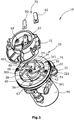
- the Figure 1 shows a vane cell gas pump 10 designed as a so-called vacuum pump, which is intended, for example, for use in a motor vehicle and can generate an absolute pressure of, for example, 100 mbar or less.
- the vane pump 10 has a metal pump housing 20 which forms a pump chamber 22.
- the pump housing 20 is essentially composed of a cam ring 74, a base plate 76 and a valve cover 72.
- a pump rotor 30 is rotatably arranged in the pump chamber 22 eccentrically to the center of gravity of the pump chamber 22.
- the Pump rotor 30 has five slide slots 321, 341, 361, 381, 401, in each of which a slide element 32, 34, 36, 38, 40 is slidably mounted.
- the five slide elements 32, 34, 36, 38, 40 divide the pump chamber 22 into five rotating pump compartments, each of which has the same pump compartment angle a.
- the pump rotor 30 is driven by an electric motor 90.
- the pump chamber 22 can be divided into several sectors, namely an inlet sector 42 with a fluid inlet opening 60, an outlet sector 44 with a first fluid outlet opening 52 and a second fluid outlet opening 54 and a sealing sector 46, which is arranged in the direction of rotation between the outlet sector 44 and the inlet sector 42 and prevents gas flow from the fluid outlet ports 52, 54 to the fluid inlet port 60.
- the fluid inlet opening 60 is formed in the bottom plate 76.
- the two fluid outlet openings 52, 54 are formed in the valve cover 72.
- the first fluid outlet opening 52 is arranged in the direction of rotation of the pump rotor 30 in front of the second fluid outlet opening 54.
- the first fluid outlet opening 52 is fluidly assigned a check valve 70, the check valve 70 being a tongue valve and having a valve tongue 80 and a travel limiter 82, both of which are fixedly arranged on the valve cover 72.
- No valve is assigned to the second fluid outlet opening 54, so that the second fluid outlet opening 54 is permanently open and permits a fluid flow without resistance.
- the second fluid outlet opening 54 is spaced at an angular distance b from the first fluid outlet opening 52, the angular distance b being measured between a leading edge of the second fluid outlet opening 54 and the trailing edge of the first fluid outlet opening 52.
- the angular distance b is smaller than one by two Adjacent slide elements 32, 34, 36, 38, 40 included pump compartment angle a, so that a pump compartment passing through the outlet sector 44 is always fluidly connected to at least one fluid outlet opening 52, 54.
- the air is sucked in by the rotation of the pump rotor 30 through the fluid inlet opening 60 and is expelled from the pump compartment through the two fluid outlet openings 52, 54.
- the first fluid outlet opening 52 is released and the air is expelled through the first fluid outlet opening 52.
- the air is exhausted through the second fluid outlet port 54. Because no valve is assigned to the second fluid outlet opening 54, the air is expelled without resistance, and no pressure build-up generated by the check valve is generated. In this way, the tangential load on the slide elements 32, 34, 36, 38, 40 decreases and the wear on the slide elements 32, 34, 36, 38, 40 is reduced. In addition, the power consumption of the electric motor 90 is reduced and the achievable final pressure is reduced.
- the number of slide elements can vary or the fluid inlet opening and / or the fluid outlet openings can be formed on other housing components.
Landscapes
- Engineering & Computer Science (AREA)
- Mechanical Engineering (AREA)
- General Engineering & Computer Science (AREA)
- Applications Or Details Of Rotary Compressors (AREA)
- Rotary Pumps (AREA)
- Compressors, Vaccum Pumps And Other Relevant Systems (AREA)
Description
- Die Erfindung betrifft eine trockenlaufende Flügelzellen-Gaspumpe.
- Derartige Flügelzellen-Gaspumpen sind aus dem Stand der Technik bekannt und werden in Kraftfahrzeugen als sogenannte Vakuumpumpen üblicherweise in Kombination mit einem Bremskraftverstärker eingesetzt. Die Flügelzellenpumpe liefert dabei den zum Betrieb des Bremskraftverstärkers benötigten Unterdruck, wobei dieser in der Regel absolut 100 mbar oder weniger beträgt.
- Die aus dem Stand der Technik bekannten Flügelzellen-Gaspumpen sind üblicherweise trockenlaufende oder ölgeschmierte Flügelzellen-Gaspumpen, wobei bei trockenlaufenden Gaspumpen kein Schmiermittel in die Pumpkammer geleitet wird. Bei ölgeschmierten Flügelzellenpumpen ist die aus der Pumpkammer austretende Luft mit Schmiermittel vermischt, wobei vor der Entsorgung dieses Luft-Schmiermittel-Gemisches das Luft-Schmiermittel-Gemisch aufwendig in seine Bestandteile getrennt werden muss. Durch Weglassen des Schmiermittels kann die Kontamination der die Pumpkammer verlassenden Luft vermieden werden. Das Weglassen des Schmiermittels führt aber zu einem erhöhten Verschleiß der sich relativ zueinander bewegenden Bauteile, insbesondere der Schieberelemente. Der Verschleiß wird üblicherweise durch gezielte Wahl geeigneter Werkstoffpaarungen der aneinander anliegenden und sich zueinander relativ bewegenden Bauteile auf ein Minimum reduziert.
- Eine derartige trockenlaufende Flügelzellen-Gaspumpe ist in der
EP 2 568 180 A1 offenbart. Die Flügelzellenpumpe weist ein Pumpengehäuse auf, welches eine Pumpkammer bildet. In der Pumpkammer ist ein Pumpenrotor angeordnet, der fünf radial verschiebbare Schieberelemente aufweist. Der Pumpenrotor ist mit einem Elektromotor drehfest verbunden und wird durch diesen angetrieben. Bei einem rotierenden Pumpenrotor verschieben sich die Schieberelemente aufgrund der auf die Schieberelemente wirkenden Fliehkraft derart, dass diese mit ihrem Kopf jeweils an einer Umfangswand der Pumpkammer anliegen, wobei jeweils zwei benachbarte Schieberelemente gemeinsam mit dem Pumpenrotor und dem Pumpengehäuse jeweils ein Pumpfach begrenzen. In dem Pumpengehäuse sind eine Fluideinlassöffnung und zwei Fluidauslassöffnungen ausgebildet, wobei die Fluideinlassöffnung und die Fluidauslassöffnungen der Pumpkammer zugeordnet sind. Beide Fluidauslassöffnungen weisen jeweils ein Rückschlagventil auf, so dass die Fluidauslassöffnungen erst ab einem in dem Pumpfach herrschenden vordefinierten Überdrucks freigegeben werden. - Nachteilig an der in der
EP 2 568 180 A1 offenbarten Ausführung ist, dass beim Ausstoßen der Luft über die beiden Fluidauslassöffnungen sowohl das der ersten Fluidauslassöffnung zugeordnete Rückschlagventil als auch das der zweiten Fluidauslassöffnung zugeordnete Rückschlagventil die drucklose Luft am Herausströmen hindern, so dass in dem Pumpfach im Auslasssektor stets ein gewisser Überdruck herrscht. Hierdurch werden die Schieberelemente mechanisch belastet, wodurch der mechanische Verschleiß der Schieberelemente, die Leistungsaufnahme des Elektromotors sowie der erreichbare Enddruck ansteigen. - Der Erfindung liegt daher die Aufgabe zugrunde, den oben genannten Nachteil zu vermeiden.
- Diese Aufgabe wird durch eine trockenlaufende Gaspumpe mit den Merkmalen des Hauptanspruchs gelöst.
- Die trockenlaufende Gaspumpe weist ein Pumpengehäuse auf, welches eine Pumpkammer begrenzt. In der Pumpkammer ist ein Pumpenrotor angeordnet, der entweder elektrisch durch einen Elektromotor oder mechanisch durch einen Verbrennungsmotor angetrieben wird. Der Pumpenrotor ist exzentrisch in der Pumpkammer angeordnet und liegt in einem Dichtsektor an der Umfangswand der Pumpkammer an, wodurch ein sichelförmiger Arbeitsraum geschaffen wird.
- In dem Pumpenrotor ist mindestens ein verschiebbares Schieberelement gelagert. Zur Lagerung des mindestens einen Schieberelements weist der Pumpenrotor einen Schieberschlitz auf, in dem das mindestens eine Schieberelement verschiebbar angeordnet ist. Bei einem rotierenden Pumpenrotor verschiebt sich das mindestens eine Schieberelement aufgrund der auf das Schieberelement wirkenden Fliehkraft derart, dass das Schieberelement mit seinem Kopf stets an der Umfangswand der Pumpkammer anliegt. Zusätzlich kann das mindestens eine Schieberelement federbelastet sein, so dass der Kopf des mindestens einen Schieberelements durch die Federkraft an der Umfangswand der Pumpkammer auch bei geringen Drehzahlen anliegt.
- Die Pumpkammer ist bezüglich der Funktion in einen Einlass-, einen Auslass- und einen Dichtsektor eingeteilt. In dem Einlasssektor ist eine Fluideinlassöffnung angeordnet, die beispielsweise mit einer Unterdruckkammer eines Bremskraftverstärkers fluidisch verbunden ist. In dem Auslasssektor sind eine erste Fluidauslassöffnung und eine zweite Fluidauslassöffnung angeordnet, wobei über die Fluidauslassöffnungen die Pumpkammer mit der Umgebung verbindbar ist. Zwischen den Fluidauslassöffnungen und der Fluideinlassöffnung ist, gesehen in Drehrichtung, der Dichtsektor angeordnet, der einen Gasstrom zwischen der Fluideinlassöffnung und den Fluidauslassöffnungen verhindert.
- Die erste Fluidauslassöffnung ist in Drehrichtung des Pumpenrotors vor der zweiten Fluidauslassöffnung angeordnet, wobei der ersten Fluidauslassöffnung ein Rückschlagventil zugeordnet ist. Das Rückschlagventil verschließt die erste Fluidauslassöffnung und gibt diese ab einem vordefinierten im Pumpfach herrschenden Überdruck frei. Die zweite Fluidauslassöffnung weist kein Rückschlagventil auf, so dass die zweite Fluidauslassöffnung dauerhaft offen ist.
- Im Betrieb wird über die Fluideinlassöffnung Luft in das passierende Pumpfach angesaugt und über die erste und die zweite Fluidauslassöffnung aus dem Pumpfach ausgestoßen. Die Luft wird durch die erste Fluidauslassöffnung ausgestoßen, solange ein in dem Pumpfach herrschender Druck den zum Betätigen des Rückschlagventils benötigten Öffnungsdruck übersteigt. Zusätzlich wird die Luft durch die zweite Fluidauslassöffnung ausgestoßen, wobei der zweiten Fluidauslassöffnung kein Rückschlagventil zugeordnet ist, so dass die Luft widerstandslos aus dem Pumpfach strömen kann. Dadurch, dass der zweiten Fluidauslassöffnung kein Rückschlagventil zugeordnet ist und die Luft widerstandlos aus dem Pumpfach ausgestoßen werden kann, wird in diesem Bereich ein Überdruck vermieden. Dadurch wird die mechanische Belastung auf das mindestens eine Schieberelement reduziert und ist der Verschleiß des mindestens einen Schieberelements reduziert.
- Vorzugsweise sind in dem Pumpenrotor mindestens zwei Schieberelemente gelagert, wodurch der hydraulische Wirkungsgrad der Flügelzellenpumpe erhöht wird, indem mit steigender Anzahl der Schieberelemente die Leckage zwischen der Druckseite und der Saugseite erheblich reduziert wird.
- In einer bevorzugten Ausgestaltung ist der Winkelabstand zwischen der ersten Fluidauslassöffnung und der zweiten Fluidauslassöffnung kleiner als der Pumpfachwinkel. Der Winkelabstand ist definiert als der Winkelabstand zwischen der nachlaufenden Kante der ersten Fluidauslassöffnung und der vorlaufenden Kante der zweiten Fluidauslassöffnung. Der Pumpfachwinkel wird durch zwei benachbarte Schieberelemente definiert. Dadurch, dass der Winkelabstand zwischen der ersten und der zweiten Fluidauslassöffnung kleiner als der Pumpfachwinkel ist, ist das Pumpfach im Auslasssektor zu jedem Zeitpunkt mit mindestens einer Fluidauslassöffnung fluidisch verbunden. Auf diese Weise wird ein Druckaufbau in dem Pumpfach vermieden, der entstehen würde, wenn das Pumpfach im Auslasssektor kurzzeitig mit keiner der beiden Fluidauslassöffnungen fluidisch verbunden wäre, und die auszustoßende Luft nicht abströmen könnte. Dadurch ist die mechanische tangentiale Belastung auf das Schieberelement reduziert.
- Vorzugsweise entspricht die tangentiale Breite B1 des mindestens einen Schieberelements mindestens der tangentialen Breite B2 der ersten Fluidauslassöffnung, wodurch die zweite Fluidauslassöffnung beim Überfahren durch das mindestens eine Schieberelement vollständig abgedeckt und kurzzeitig verschlossen wird. Dadurch wird ein Kurzschluss zwischen den durch das mindestens eine Schieberelement begrenzenden Pumpfächern verhindert, und wird der pneumatische Wirkungsgrad der Gaspumpe erhöht.
- In einer bevorzugten Ausgestaltung besteht zumindest der Kopf des mindestens einen Schieberelements aus Graphit. Auf diese Weise erfolgt eine Trockenschmierung, wobei der aus Graphit ausgeführte Kopf des Schieberelements mit fortschreitender Lebensdauer kontrolliert verschleißt. Graphit ist relativ weich. Insbesondere bei einem aus Graphit hergestellten Schieberelement-Kopf wird der mechanische Verschleiß des Kopfes durch die Erfindung erheblich reduziert.
- Vorzugsweise weist das Pumpengehäuse einen Ventildeckel, einen Hubring und einen Bodendeckel auf. Der Hubring bildet die Umfangsfläche der Pumpkammer und liegt mit seiner Stirnseite an dem Ventildeckel und mit seiner anderen Stirnseite an dem Bodendeckel dichtend an. Der Ventildeckel schließt die Pumpkammer einseitig ab und weist die mindestens zwei Fluidauslassöffnungen auf. Vorzugsweise weist das Bodenelement die Fluideinlassöffnung auf.
- In einer bevorzugten Ausgestaltung ist das Rückschlagventil ein Zungenventil mit einem Wegbegrenzer. Ein derartig ausgeführtes Rückschlagventil ist kostengünstig herstellbar, zuverlässig und einfach montierbar.
- Die Erfindung wird anhand der Zeichnungen näher erläutert. Hierbei zeigen:
- Die
Figur 1 zeigt eine Explosionsdarstellung einer trockenlaufenden Flügelzellen-Gaspumpe, und - Die
Figur 2 zeigt eine schematische Frontalansicht einer Anlaufscheibe einer trockenlaufenden Flügelzellen-Gaspumpe ausFigur 1 . - Die
Figur 1 zeigt eine als sogenannte Vakuumpumpe ausgebildete Flügelzellen-Gaspumpe 10, die beispielsweise für den Einsatz in einem Kraftfahrzeug bestimmt ist und einen Absolutdruck von beispielsweise 100 mbar oder weniger erzeugen kann. Die Flügelzellenpumpe 10 weist ein Metall-Pumpengehäuse 20 auf, welches eine Pumpkammer 22 bildet. Das Pumpengehäuse 20 setzt sich im Wesentlichen aus einem Hubring 74, einer Bodenplatte 76 und einem Ventildeckel 72 zusammen. - In der Pumpkammer 22 ist exzentrisch zum Schwerpunkt der Pumpkammer 22 ein Pumpenrotor 30 drehbar angeordnet. Der Pumpenrotor 30 weist fünf Schieberschlitze 321, 341, 361, 381, 401 auf, in welchen jeweils ein Schieberelement 32, 34, 36, 38, 40 verschiebbar gelagert ist. Die fünf Schieberelemente 32, 34, 36, 38, 40 teilen die Pumpkammer 22 in fünf rotierende Pumpfächer auf, die jeweils den gleichen Pumpfachwinkel a aufweisen. Der Pumpenrotor 30 wird vorliegend von einem Elektromotor 90 angetrieben.
- Die Pumpkammer 22 lässt sich in mehrere Sektoren einteilen, nämlich einen Einlasssektor 42 mit einer Fluideinlassöffnung 60, einen Auslasssektor 44 mit einer ersten Fluidauslassöffnung 52 sowie einer zweiten Fluidauslassöffnung 54 und einen Dichtsektor 46, der in Drehrichtung gesehen zwischen dem Auslasssektor 44 und dem Einlasssektor 42 angeordnet ist und der einen Gasstrom von den Fluidauslassöffnungen 52, 54 zu der Fluideinlassöffnung 60 verhindert.
- Die Fluideinlassöffnung 60 ist in der Bodenplatte 76 ausgebildet. Die beiden Fluidauslassöffnungen 52, 54 sind in dem Ventildeckel 72 ausgebildet. Die erste Fluidauslassöffnung 52 ist in Drehrichtung des Pumpenrotors 30 vor der zweiten Fluidauslassöffnung 54 angeordnet. Der ersten Fluidauslassöffnung 52 ist fluidisch ein Rückschlagventil 70 zugeordnet, wobei das Rückschlagventil 70 ein Zungenventil ist und eine Ventilzunge 80 und einen Wegbegrenzer 82 aufweist, welche beide an dem Ventildeckel 72 fest angeordnet sind. Der zweiten Fluidauslassöffnung 54 ist kein Ventil zugeordnet, so dass die zweite Fluidauslassöffnung 54 dauerhaft offen ist und einen widerstandslosen Fluidfluss zulässt.
- Die zweite Fluidauslassöffnung 54 ist in einem Winkelabstand b zur ersten Fluidauslassöffnung 52 beabstandet, wobei der Winkelabstand b zwischen einer vorlaufenden Kante der zweiten Fluidauslassöffnung 54 und der nachlaufenden Kante der ersten Fluidauslassöffnung 52 gemessen wird. Der Winkelabstand b ist kleiner als ein durch zwei benachbarte Schieberelemente 32, 34, 36, 38, 40 eingeschlossener Pumpfachwinkel a, so dass ein den Auslasssektor 44 durchfahrendes Pumpfach immer mit mindestens einer Fluidauslassöffnung 52, 54 fluidisch verbunden ist.
- Im Betrieb der Gaspumpe 10 wird die Luft durch die Rotation des Pumpenrotors 30 durch die Fluideinlassöffnung 60 angesaugt und durch die beiden Fluidauslassöffnungen 52, 54 aus dem Pumpfach ausgestoßen. Solange in dem Pumpfach ein vordefinierter Überdruck herrscht, ist die erste Fluidauslassöffnung 52 freigegeben und die Luft wird durch die erste Fluidauslassöffnung 52 ausgestoßen. Zusätzlich wird die Luft durch die zweite Fluidauslassöffnung 54 ausgestoßen. Dadurch, dass der zweiten Fluidauslassöffnung 54 kein Ventil zugeordnet ist, wird die Luft widerstandslos ausgestoßen, wobei kein durch das Rückschlagventil erzeugter Druckaufbau erzeugt wird. Auf diese Weise sinkt die tangentiale Belastung auf die Schieberelemente 32, 34, 36, 38, 40 und der Verschleiß der Schieberelemente 32, 34, 36, 38, 40 wird reduziert. Außerdem wird die Leistungsaufnahme des Elektromotors 90 gesenkt und der erreichbare Enddruck gesenkt.
- Es sollte deutlich sein, dass auch andere konstruktive Ausführungsformen der trockenlaufenden Gaspumpe im Vergleich zur beschriebenen Ausführungsform möglich sind, ohne den Schutzbereich des Hauptanspruchs zu verlassen. Es kann beispielsweise die Anzahl der Schieberelemente variieren oder die Fluideinlassöffnung und/oder die Fluidauslassöffnungen an anderen Gehäusebauteilen ausgebildet sein.
Claims (8)
- Trockenlaufende Flügelzellen-Gaspumpe (10), mit
einem Pumpengehäuse (20), das eine Pumpkammer (22) bildet, in der ein Pumpenrotor (30) mit mindestens einem verschiebbaren Schieberelement (32, 34, 36, 38, 40) drehbar gelagert ist,
wobei der Pumpkammer (22) mindestens eine Fluideinlassöffnung (60) und mindestens zwei Fluidauslassöffnungen (52, 54) zugeordnet sind, und
wobei eine erste Fluidauslassöffnung (52) der mindestens zwei Fluidauslassöffnungen (52, 54) durch ein Rückschlagventil (70) verschließbar ist,
dadurch gekennzeichnet, dass
eine zweite Fluidauslassöffnung (54) der mindestens zwei Fluidauslassöffnungen (52,54) dauerhaft offen ist,
wobei die erste Fluidauslassöffnung (52) in Drehrichtung des Pumpenrotors (30) vor der zweiten Fluidauslassöffnung (54) angeordnet ist. - Trockenlaufende Flügelzellen-Gaspumpe (10) nach Anspruch 1,
dadurch gekennzeichnet, dass
in dem Pumpenrotor (30) mindestens zwei Schieberelemente (32, 34, 36, 38, 40) gelagert sind. - Trockenlaufende Flügelzellen-Gaspumpe (10) nach einem der vorhergehenden Ansprüche,
dadurch gekennzeichnet, dass
der Winkelabstand b zwischen der ersten Fluidauslassöffnung (52) und der zweiten Fluidauslassöffnung (54) kleiner als der Pumpfachwinkel a ist, wobei der Pumpfachwinkel a durch zwei benachbarte Schieberelemente (32, 34, 36, 38, 40) eingeschlossen ist. - Trockenlaufende Flügelzellen-Gaspumpe (10) nach einem der vorhergehenden Ansprüche,
dadurch gekennzeichnet, dass
die Breite B1 des Schieberelements (32, 34, 36, 38, 40) mindestens der tangentialen Breite B2 der ersten Fluidauslassöffnung (52) entspricht. - Trockenlaufende Flügelzellen-Gaspumpe (10) nach einem der vorhergehenden Ansprüche,
dadurch gekennzeichnet, dass
zumindest der Kopf (62) des mindestens einen Schieberelements (32, 34, 36, 38, 40) aus Graphit besteht. - Trockenlaufende Flügelzellen-Gaspumpe (10) nach einem der vorhergehenden Ansprüche,
dadurch gekennzeichnet, dass
das Gehäuse (20) einen Ventildeckel (72), einen Hubring (74) und ein Bodendeckel (76) aufweist, welche eine Pumpkammer (22) begrenzen, wobei der Ventildeckel (72) die mindestens zwei Fluidauslausöffnungen (52, 54) aufweist. - Trockenlaufende Flügelzellen-Gaspumpe (10) nach Anspruch 6,
dadurch gekennzeichnet, dass
die Fluideinlassöffnung (60) an dem Bodendeckel ausgebildet ist. - Trockenlaufende Flügelzellen-Gaspumpe (10) nach einem der vorhergehenden Ansprüche,
dadurch gekennzeichnet, dass
das Rückschlagventil (70) ein Zungenventil (80) mit einem Wegbegrenzer (82) ist.
Applications Claiming Priority (2)
| Application Number | Priority Date | Filing Date | Title |
|---|---|---|---|
| PCT/EP2016/064429 WO2017220141A1 (de) | 2016-06-22 | 2016-06-22 | Kfz-vakuumpumpen-anordnung |
| PCT/EP2017/052166 WO2017220212A1 (de) | 2016-06-22 | 2017-02-01 | Trockenlaufende flügelzellen-gaspumpe |
Publications (2)
| Publication Number | Publication Date |
|---|---|
| EP3475574A1 EP3475574A1 (de) | 2019-05-01 |
| EP3475574B1 true EP3475574B1 (de) | 2020-04-01 |
Family
ID=56194488
Family Applications (2)
| Application Number | Title | Priority Date | Filing Date |
|---|---|---|---|
| EP16731591.0A Active EP3475573B1 (de) | 2016-06-22 | 2016-06-22 | Kfz-vakuumpumpen-anordnung |
| EP17713583.7A Active EP3475574B1 (de) | 2016-06-22 | 2017-02-01 | Trockenlaufende flügelzellen-gaspumpe |
Family Applications Before (1)
| Application Number | Title | Priority Date | Filing Date |
|---|---|---|---|
| EP16731591.0A Active EP3475573B1 (de) | 2016-06-22 | 2016-06-22 | Kfz-vakuumpumpen-anordnung |
Country Status (5)
| Country | Link |
|---|---|
| US (2) | US11261869B2 (de) |
| EP (2) | EP3475573B1 (de) |
| JP (1) | JP2019518905A (de) |
| CN (2) | CN109154293B (de) |
| WO (2) | WO2017220141A1 (de) |
Families Citing this family (2)
| Publication number | Priority date | Publication date | Assignee | Title |
|---|---|---|---|---|
| US11261868B2 (en) * | 2017-02-01 | 2022-03-01 | Pierburg Pump Technology Gmbh | Vane gas pump with sliding element trmporaily completely covering the elongated fluid outlet opening |
| CN113374691B (zh) * | 2021-06-04 | 2023-01-20 | 淄博真空设备厂有限公司 | 一种汽车节能真空泵 |
Family Cites Families (55)
| Publication number | Priority date | Publication date | Assignee | Title |
|---|---|---|---|---|
| US2772637A (en) * | 1952-03-20 | 1956-12-04 | Jabsco Pump Co | Impeller pump |
| US3016184A (en) * | 1959-01-19 | 1962-01-09 | Scaife Company | Rotary compressors |
| US3267862A (en) * | 1964-03-16 | 1966-08-23 | Roper Ind Inc | Apparatus for pumping and separating liquid and gaseous fluids |
| DE1553283A1 (de) * | 1964-08-17 | 1969-09-25 | Zahnradfabrik Friedrichshafen | Fluegelzellen-Kapselwerk |
| US3642095A (en) * | 1968-03-22 | 1972-02-15 | Fujii Koygo Kk | Muffler |
| US3459275A (en) | 1968-08-05 | 1969-08-05 | Niles Pressluftwerkzeuge Veb | Soundproof compressed-air machine |
| GB1303430A (de) * | 1969-06-12 | 1973-01-17 | ||
| US3790314A (en) * | 1972-05-22 | 1974-02-05 | Abex Corp | Vane pump having extended undervane suction ports |
| CA1080121A (en) * | 1977-12-19 | 1980-06-24 | Edward A. Kempton | Water removal system for gas wells |
| US4204816A (en) * | 1978-09-08 | 1980-05-27 | The United States Of America As Represented By The Secretary Of The Navy | Discharge and pressure relief ports for mechanisms with involute shaped vanes |
| JPS5641187U (de) * | 1979-09-06 | 1981-04-16 | ||
| JPS5641187A (en) | 1979-09-10 | 1981-04-17 | Sumitomo Heavy Industries | Method and device for prementing spontaneous combustion of coal in coal storage tank |
| US4737088A (en) * | 1985-03-01 | 1988-04-12 | Daikin Kogyo Co., Ltd. | Rotary compressor with oil relief passage |
| JPS6293496A (ja) * | 1985-10-18 | 1987-04-28 | Hitachi Ltd | 回転ベ−ン式ポンプ |
| US4746280A (en) * | 1987-02-19 | 1988-05-24 | Corken International Corporation | Sliding vane pump |
| JPH01208590A (ja) * | 1988-02-10 | 1989-08-22 | Diesel Kiki Co Ltd | 圧縮機 |
| DE3909831A1 (de) * | 1989-03-25 | 1990-09-27 | Becker Kg Gebr | Trockenlaufende drehschiebervakuumpumpe sowie verfahren zu deren herstellung |
| US5342183A (en) * | 1992-07-13 | 1994-08-30 | Copeland Corporation | Scroll compressor with discharge diffuser |
| US5310326A (en) * | 1992-09-14 | 1994-05-10 | Mainstream Engineering Corporation | Rotary compressor with improved bore configuration and lubrication system |
| US5378111A (en) * | 1993-06-21 | 1995-01-03 | General Motors Corporation | Motor vehicle fuel pump assembly with pressure relief orifice |
| US5536153A (en) * | 1994-06-28 | 1996-07-16 | Edwards; Thomas C. | Non-contact vane-type fluid displacement machine with lubricant separator and sump arrangement |
| US5716201A (en) * | 1995-07-31 | 1998-02-10 | Coltec Industries Inc. | Variable displacement vane pump with vane tip relief |
| US6872065B1 (en) * | 1996-09-06 | 2005-03-29 | Seiko Seiki Kabushiki Kaisha | Vane gas compressor having two discharge passages with the same length |
| US6528907B2 (en) * | 2000-04-07 | 2003-03-04 | Mirae Corporation | Linear motor |
| JP3943826B2 (ja) * | 2000-11-09 | 2007-07-11 | 株式会社日立製作所 | オイルポンプ |
| US6739850B2 (en) * | 2001-10-25 | 2004-05-25 | Kyosan Denki Co., Ltd. | Motor-type fuel pump for vehicle |
| CN101676563B (zh) * | 2008-09-20 | 2011-07-20 | 比亚迪股份有限公司 | 一种真空泵 |
| US9074588B2 (en) * | 2009-05-06 | 2015-07-07 | Amir Khajepour | Air compression method and apparatus |
| KR100953626B1 (ko) * | 2009-06-18 | 2010-04-20 | 캄텍주식회사 | 차량용 진공펌프 |
| DE102010029551A1 (de) | 2010-06-01 | 2011-12-01 | Robert Bosch Gmbh | Geräuschreduzierte Gaspumpe |
| CN201786661U (zh) | 2010-06-18 | 2011-04-06 | 大连市铭源全科技开发有限公司 | 微型油封式双级真空泵 |
| DE102010044898A1 (de) * | 2010-09-09 | 2012-03-15 | Schwäbische Hüttenwerke Automotive GmbH | Vakuumpumpe mit Lüftungseinrichtung |
| JP5607492B2 (ja) * | 2010-10-20 | 2014-10-15 | 日信工業株式会社 | 負圧ポンプ |
| US8608465B2 (en) * | 2011-06-30 | 2013-12-17 | Peopleflo Manufacturing, Inc. | Positive-displacement rotary pump having a positive-displacement auxiliary pumping system |
| EP2568180B1 (de) | 2011-09-12 | 2019-11-13 | Pierburg Pump Technology GmbH | Flügelzellenpumpe |
| US9751384B2 (en) * | 2011-11-24 | 2017-09-05 | Calsonic Kansei Corporation | Gas compressor with discharge section and sub-discharge section |
| JP5774134B2 (ja) * | 2012-01-11 | 2015-09-02 | 三菱電機株式会社 | ベーン型圧縮機 |
| JP2013241907A (ja) | 2012-05-22 | 2013-12-05 | Taiho Kogyo Co Ltd | バキュームポンプ |
| JP5963544B2 (ja) * | 2012-05-31 | 2016-08-03 | カルソニックカンセイ株式会社 | 気体圧縮機 |
| JP5913199B2 (ja) * | 2012-06-05 | 2016-04-27 | カルソニックカンセイ株式会社 | 気体圧縮機 |
| JP5828863B2 (ja) * | 2012-08-22 | 2015-12-09 | カルソニックカンセイ株式会社 | 気体圧縮機 |
| CN102878080A (zh) * | 2012-10-30 | 2013-01-16 | 东风汽车公司 | 电动真空泵 |
| CN102943759A (zh) * | 2012-11-13 | 2013-02-27 | 吉林东光奥威汽车制动系统有限公司 | 一种电动真空泵 |
| DE102012112069A1 (de) | 2012-12-11 | 2014-06-12 | Hella Kgaa Hueck & Co. | Pumpe |
| WO2014135202A1 (de) | 2013-03-05 | 2014-09-12 | Pierburg Pump Technology Gmbh | Elektrische kfz-vakuumpumpen-anordnung |
| DE102013104375A1 (de) * | 2013-04-30 | 2014-10-30 | Hella Kgaa Hueck & Co. | Vakuumpumpe |
| KR101530568B1 (ko) * | 2013-12-10 | 2015-06-22 | 영신정공 주식회사 | 소음 감소를 위한 전동 진공 펌프 |
| US20150260088A1 (en) * | 2014-03-14 | 2015-09-17 | Chung-Shan Institute Of Science And Technology, Armaments Bureau, M.N.D | Intake/outlet pipe optimization method for rotary engine |
| JP2016044606A (ja) | 2014-08-22 | 2016-04-04 | 愛三工業株式会社 | バキュームポンプ |
| JP2016048057A (ja) * | 2014-08-28 | 2016-04-07 | 愛三工業株式会社 | バキュームポンプ |
| CN204402889U (zh) | 2014-11-26 | 2015-06-17 | 淄博瑞莱特真空设备有限公司 | 一种新型干式真空泵结构 |
| CN105065281B (zh) | 2015-08-05 | 2017-05-24 | 同济大学 | 一种多排气压力螺杆式压缩机 |
| KR102522991B1 (ko) * | 2016-12-29 | 2023-04-18 | 엘지전자 주식회사 | 밀폐형 압축기 |
| US11261868B2 (en) * | 2017-02-01 | 2022-03-01 | Pierburg Pump Technology Gmbh | Vane gas pump with sliding element trmporaily completely covering the elongated fluid outlet opening |
| US10697309B2 (en) * | 2018-04-25 | 2020-06-30 | Raytheon Technologies Corporation | Platform cover plates for gas turbine engine components |
-
2016
- 2016-06-22 EP EP16731591.0A patent/EP3475573B1/de active Active
- 2016-06-22 US US16/311,168 patent/US11261869B2/en active Active
- 2016-06-22 CN CN201680086050.3A patent/CN109154293B/zh active Active
- 2016-06-22 WO PCT/EP2016/064429 patent/WO2017220141A1/de not_active Ceased
-
2017
- 2017-02-01 WO PCT/EP2017/052166 patent/WO2017220212A1/de not_active Ceased
- 2017-02-01 EP EP17713583.7A patent/EP3475574B1/de active Active
- 2017-02-01 US US16/310,817 patent/US10995757B2/en active Active
- 2017-02-01 CN CN201780031711.7A patent/CN109154294B/zh active Active
- 2017-02-01 JP JP2018567038A patent/JP2019518905A/ja active Pending
Non-Patent Citations (1)
| Title |
|---|
| None * |
Also Published As
| Publication number | Publication date |
|---|---|
| CN109154293B (zh) | 2021-04-13 |
| EP3475573B1 (de) | 2020-08-05 |
| US20190323506A1 (en) | 2019-10-24 |
| WO2017220141A1 (de) | 2017-12-28 |
| US20200309134A1 (en) | 2020-10-01 |
| CN109154294B (zh) | 2019-12-31 |
| CN109154293A (zh) | 2019-01-04 |
| WO2017220212A1 (de) | 2017-12-28 |
| CN109154294A (zh) | 2019-01-04 |
| EP3475574A1 (de) | 2019-05-01 |
| EP3475573A1 (de) | 2019-05-01 |
| US11261869B2 (en) | 2022-03-01 |
| JP2019518905A (ja) | 2019-07-04 |
| US10995757B2 (en) | 2021-05-04 |
Similar Documents
| Publication | Publication Date | Title |
|---|---|---|
| DE102012201615B4 (de) | variable kombinierte Öl-Vakuum-Verdrängerpumpe | |
| DE3800324A1 (de) | Fluegelzellenverdichter | |
| DE112013003254T5 (de) | Rotationskompressor | |
| DE102016121241B4 (de) | Hydraulischer Antrieb, hydraulischer Motor und integrierte Pumpe mit dem hydraulischen Antrieb | |
| DE102004034926B3 (de) | Einflügelvakuumpumpe | |
| EP3475574B1 (de) | Trockenlaufende flügelzellen-gaspumpe | |
| DE102009037443A1 (de) | Selbstansaugende Flügelzellenpumpe | |
| DE2131000A1 (de) | Drehfluegelkompressor | |
| DE2850371C2 (de) | ||
| DE112016002389T5 (de) | Kompressor vom Zylinderrotations-Typ | |
| DE3826548C2 (de) | Flügelzellenverdichter mit variabler Förderleistung | |
| EP3577342B1 (de) | Flügelzellen-gaspumpe | |
| DE4008522C2 (de) | ||
| WO2003067032A1 (de) | Druckluftmotor | |
| DE3046973A1 (de) | Schaufel-verdichter | |
| DE102008014243A1 (de) | Flügelzellenpumpe | |
| DE2654991C3 (de) | Drehschieberkompressor | |
| DE3801306A1 (de) | Fluegelzellenverdichter | |
| DE2054033A1 (en) | Multicell compressor - with ptfe check plate | |
| DE102013224660A1 (de) | Flügelzellenmaschine mit definiertem Druck in den Hinterflügelräumen | |
| DE2233580A1 (de) | Kompressor | |
| WO2018141419A1 (de) | Flügelzellen-gaspumpe | |
| DE2744591A1 (de) | Pumpe | |
| EP2574792B1 (de) | Flügelzellenpumpe | |
| DE102022109215A1 (de) | Elektrische Kfz-Ölpumpe |
Legal Events
| Date | Code | Title | Description |
|---|---|---|---|
| STAA | Information on the status of an ep patent application or granted ep patent |
Free format text: STATUS: UNKNOWN |
|
| STAA | Information on the status of an ep patent application or granted ep patent |
Free format text: STATUS: THE INTERNATIONAL PUBLICATION HAS BEEN MADE |
|
| PUAI | Public reference made under article 153(3) epc to a published international application that has entered the european phase |
Free format text: ORIGINAL CODE: 0009012 |
|
| STAA | Information on the status of an ep patent application or granted ep patent |
Free format text: STATUS: REQUEST FOR EXAMINATION WAS MADE |
|
| 17P | Request for examination filed |
Effective date: 20181219 |
|
| AK | Designated contracting states |
Kind code of ref document: A1 Designated state(s): AL AT BE BG CH CY CZ DE DK EE ES FI FR GB GR HR HU IE IS IT LI LT LU LV MC MK MT NL NO PL PT RO RS SE SI SK SM TR |
|
| AX | Request for extension of the european patent |
Extension state: BA ME |
|
| DAV | Request for validation of the european patent (deleted) | ||
| DAX | Request for extension of the european patent (deleted) | ||
| GRAP | Despatch of communication of intention to grant a patent |
Free format text: ORIGINAL CODE: EPIDOSNIGR1 |
|
| STAA | Information on the status of an ep patent application or granted ep patent |
Free format text: STATUS: GRANT OF PATENT IS INTENDED |
|
| INTG | Intention to grant announced |
Effective date: 20191105 |
|
| GRAS | Grant fee paid |
Free format text: ORIGINAL CODE: EPIDOSNIGR3 |
|
| GRAA | (expected) grant |
Free format text: ORIGINAL CODE: 0009210 |
|
| STAA | Information on the status of an ep patent application or granted ep patent |
Free format text: STATUS: THE PATENT HAS BEEN GRANTED |
|
| AK | Designated contracting states |
Kind code of ref document: B1 Designated state(s): AL AT BE BG CH CY CZ DE DK EE ES FI FR GB GR HR HU IE IS IT LI LT LU LV MC MK MT NL NO PL PT RO RS SE SI SK SM TR |
|
| REG | Reference to a national code |
Ref country code: GB Ref legal event code: FG4D Free format text: NOT ENGLISH |
|
| REG | Reference to a national code |
Ref country code: AT Ref legal event code: REF Ref document number: 1251685 Country of ref document: AT Kind code of ref document: T Effective date: 20200415 Ref country code: CH Ref legal event code: EP |
|
| REG | Reference to a national code |
Ref country code: DE Ref legal event code: R096 Ref document number: 502017004508 Country of ref document: DE |
|
| REG | Reference to a national code |
Ref country code: IE Ref legal event code: FG4D Free format text: LANGUAGE OF EP DOCUMENT: GERMAN |
|
| PG25 | Lapsed in a contracting state [announced via postgrant information from national office to epo] |
Ref country code: BG Free format text: LAPSE BECAUSE OF FAILURE TO SUBMIT A TRANSLATION OF THE DESCRIPTION OR TO PAY THE FEE WITHIN THE PRESCRIBED TIME-LIMIT Effective date: 20200701 |
|
| REG | Reference to a national code |
Ref country code: NL Ref legal event code: MP Effective date: 20200401 |
|
| REG | Reference to a national code |
Ref country code: LT Ref legal event code: MG4D |
|
| PG25 | Lapsed in a contracting state [announced via postgrant information from national office to epo] |
Ref country code: SE Free format text: LAPSE BECAUSE OF FAILURE TO SUBMIT A TRANSLATION OF THE DESCRIPTION OR TO PAY THE FEE WITHIN THE PRESCRIBED TIME-LIMIT Effective date: 20200401 Ref country code: IS Free format text: LAPSE BECAUSE OF FAILURE TO SUBMIT A TRANSLATION OF THE DESCRIPTION OR TO PAY THE FEE WITHIN THE PRESCRIBED TIME-LIMIT Effective date: 20200801 Ref country code: CZ Free format text: LAPSE BECAUSE OF FAILURE TO SUBMIT A TRANSLATION OF THE DESCRIPTION OR TO PAY THE FEE WITHIN THE PRESCRIBED TIME-LIMIT Effective date: 20200401 Ref country code: PT Free format text: LAPSE BECAUSE OF FAILURE TO SUBMIT A TRANSLATION OF THE DESCRIPTION OR TO PAY THE FEE WITHIN THE PRESCRIBED TIME-LIMIT Effective date: 20200817 Ref country code: NL Free format text: LAPSE BECAUSE OF FAILURE TO SUBMIT A TRANSLATION OF THE DESCRIPTION OR TO PAY THE FEE WITHIN THE PRESCRIBED TIME-LIMIT Effective date: 20200401 Ref country code: LT Free format text: LAPSE BECAUSE OF FAILURE TO SUBMIT A TRANSLATION OF THE DESCRIPTION OR TO PAY THE FEE WITHIN THE PRESCRIBED TIME-LIMIT Effective date: 20200401 Ref country code: NO Free format text: LAPSE BECAUSE OF FAILURE TO SUBMIT A TRANSLATION OF THE DESCRIPTION OR TO PAY THE FEE WITHIN THE PRESCRIBED TIME-LIMIT Effective date: 20200701 Ref country code: GR Free format text: LAPSE BECAUSE OF FAILURE TO SUBMIT A TRANSLATION OF THE DESCRIPTION OR TO PAY THE FEE WITHIN THE PRESCRIBED TIME-LIMIT Effective date: 20200702 Ref country code: FI Free format text: LAPSE BECAUSE OF FAILURE TO SUBMIT A TRANSLATION OF THE DESCRIPTION OR TO PAY THE FEE WITHIN THE PRESCRIBED TIME-LIMIT Effective date: 20200401 |
|
| PG25 | Lapsed in a contracting state [announced via postgrant information from national office to epo] |
Ref country code: LV Free format text: LAPSE BECAUSE OF FAILURE TO SUBMIT A TRANSLATION OF THE DESCRIPTION OR TO PAY THE FEE WITHIN THE PRESCRIBED TIME-LIMIT Effective date: 20200401 Ref country code: RS Free format text: LAPSE BECAUSE OF FAILURE TO SUBMIT A TRANSLATION OF THE DESCRIPTION OR TO PAY THE FEE WITHIN THE PRESCRIBED TIME-LIMIT Effective date: 20200401 Ref country code: HR Free format text: LAPSE BECAUSE OF FAILURE TO SUBMIT A TRANSLATION OF THE DESCRIPTION OR TO PAY THE FEE WITHIN THE PRESCRIBED TIME-LIMIT Effective date: 20200401 |
|
| PG25 | Lapsed in a contracting state [announced via postgrant information from national office to epo] |
Ref country code: AL Free format text: LAPSE BECAUSE OF FAILURE TO SUBMIT A TRANSLATION OF THE DESCRIPTION OR TO PAY THE FEE WITHIN THE PRESCRIBED TIME-LIMIT Effective date: 20200401 |
|
| REG | Reference to a national code |
Ref country code: DE Ref legal event code: R097 Ref document number: 502017004508 Country of ref document: DE |
|
| PG25 | Lapsed in a contracting state [announced via postgrant information from national office to epo] |
Ref country code: DK Free format text: LAPSE BECAUSE OF FAILURE TO SUBMIT A TRANSLATION OF THE DESCRIPTION OR TO PAY THE FEE WITHIN THE PRESCRIBED TIME-LIMIT Effective date: 20200401 Ref country code: EE Free format text: LAPSE BECAUSE OF FAILURE TO SUBMIT A TRANSLATION OF THE DESCRIPTION OR TO PAY THE FEE WITHIN THE PRESCRIBED TIME-LIMIT Effective date: 20200401 Ref country code: SM Free format text: LAPSE BECAUSE OF FAILURE TO SUBMIT A TRANSLATION OF THE DESCRIPTION OR TO PAY THE FEE WITHIN THE PRESCRIBED TIME-LIMIT Effective date: 20200401 Ref country code: RO Free format text: LAPSE BECAUSE OF FAILURE TO SUBMIT A TRANSLATION OF THE DESCRIPTION OR TO PAY THE FEE WITHIN THE PRESCRIBED TIME-LIMIT Effective date: 20200401 Ref country code: ES Free format text: LAPSE BECAUSE OF FAILURE TO SUBMIT A TRANSLATION OF THE DESCRIPTION OR TO PAY THE FEE WITHIN THE PRESCRIBED TIME-LIMIT Effective date: 20200401 |
|
| PLBE | No opposition filed within time limit |
Free format text: ORIGINAL CODE: 0009261 |
|
| STAA | Information on the status of an ep patent application or granted ep patent |
Free format text: STATUS: NO OPPOSITION FILED WITHIN TIME LIMIT |
|
| PG25 | Lapsed in a contracting state [announced via postgrant information from national office to epo] |
Ref country code: PL Free format text: LAPSE BECAUSE OF FAILURE TO SUBMIT A TRANSLATION OF THE DESCRIPTION OR TO PAY THE FEE WITHIN THE PRESCRIBED TIME-LIMIT Effective date: 20200401 Ref country code: SK Free format text: LAPSE BECAUSE OF FAILURE TO SUBMIT A TRANSLATION OF THE DESCRIPTION OR TO PAY THE FEE WITHIN THE PRESCRIBED TIME-LIMIT Effective date: 20200401 |
|
| 26N | No opposition filed |
Effective date: 20210112 |
|
| PG25 | Lapsed in a contracting state [announced via postgrant information from national office to epo] |
Ref country code: SI Free format text: LAPSE BECAUSE OF FAILURE TO SUBMIT A TRANSLATION OF THE DESCRIPTION OR TO PAY THE FEE WITHIN THE PRESCRIBED TIME-LIMIT Effective date: 20200401 |
|
| PG25 | Lapsed in a contracting state [announced via postgrant information from national office to epo] |
Ref country code: MC Free format text: LAPSE BECAUSE OF FAILURE TO SUBMIT A TRANSLATION OF THE DESCRIPTION OR TO PAY THE FEE WITHIN THE PRESCRIBED TIME-LIMIT Effective date: 20200401 |
|
| GBPC | Gb: european patent ceased through non-payment of renewal fee |
Effective date: 20210201 |
|
| REG | Reference to a national code |
Ref country code: BE Ref legal event code: MM Effective date: 20210228 |
|
| PG25 | Lapsed in a contracting state [announced via postgrant information from national office to epo] |
Ref country code: LU Free format text: LAPSE BECAUSE OF NON-PAYMENT OF DUE FEES Effective date: 20210201 Ref country code: CH Free format text: LAPSE BECAUSE OF NON-PAYMENT OF DUE FEES Effective date: 20210228 Ref country code: LI Free format text: LAPSE BECAUSE OF NON-PAYMENT OF DUE FEES Effective date: 20210228 |
|
| PG25 | Lapsed in a contracting state [announced via postgrant information from national office to epo] |
Ref country code: GB Free format text: LAPSE BECAUSE OF NON-PAYMENT OF DUE FEES Effective date: 20210201 Ref country code: IE Free format text: LAPSE BECAUSE OF NON-PAYMENT OF DUE FEES Effective date: 20210201 |
|
| PG25 | Lapsed in a contracting state [announced via postgrant information from national office to epo] |
Ref country code: BE Free format text: LAPSE BECAUSE OF NON-PAYMENT OF DUE FEES Effective date: 20210228 |
|
| REG | Reference to a national code |
Ref country code: AT Ref legal event code: MM01 Ref document number: 1251685 Country of ref document: AT Kind code of ref document: T Effective date: 20220201 |
|
| PG25 | Lapsed in a contracting state [announced via postgrant information from national office to epo] |
Ref country code: AT Free format text: LAPSE BECAUSE OF NON-PAYMENT OF DUE FEES Effective date: 20220201 |
|
| PG25 | Lapsed in a contracting state [announced via postgrant information from national office to epo] |
Ref country code: CY Free format text: LAPSE BECAUSE OF FAILURE TO SUBMIT A TRANSLATION OF THE DESCRIPTION OR TO PAY THE FEE WITHIN THE PRESCRIBED TIME-LIMIT Effective date: 20200401 |
|
| PG25 | Lapsed in a contracting state [announced via postgrant information from national office to epo] |
Ref country code: HU Free format text: LAPSE BECAUSE OF FAILURE TO SUBMIT A TRANSLATION OF THE DESCRIPTION OR TO PAY THE FEE WITHIN THE PRESCRIBED TIME-LIMIT; INVALID AB INITIO Effective date: 20170201 |
|
| PG25 | Lapsed in a contracting state [announced via postgrant information from national office to epo] |
Ref country code: MK Free format text: LAPSE BECAUSE OF FAILURE TO SUBMIT A TRANSLATION OF THE DESCRIPTION OR TO PAY THE FEE WITHIN THE PRESCRIBED TIME-LIMIT Effective date: 20200401 |
|
| PG25 | Lapsed in a contracting state [announced via postgrant information from national office to epo] |
Ref country code: MT Free format text: LAPSE BECAUSE OF FAILURE TO SUBMIT A TRANSLATION OF THE DESCRIPTION OR TO PAY THE FEE WITHIN THE PRESCRIBED TIME-LIMIT Effective date: 20200401 |
|
| PG25 | Lapsed in a contracting state [announced via postgrant information from national office to epo] |
Ref country code: TR Free format text: LAPSE BECAUSE OF FAILURE TO SUBMIT A TRANSLATION OF THE DESCRIPTION OR TO PAY THE FEE WITHIN THE PRESCRIBED TIME-LIMIT Effective date: 20200401 |
|
| REG | Reference to a national code |
Ref country code: DE Ref legal event code: R082 Ref document number: 502017004508 Country of ref document: DE |
|
| PGFP | Annual fee paid to national office [announced via postgrant information from national office to epo] |
Ref country code: DE Payment date: 20260218 Year of fee payment: 10 |
|
| PGFP | Annual fee paid to national office [announced via postgrant information from national office to epo] |
Ref country code: IT Payment date: 20260224 Year of fee payment: 10 |
|
| PGFP | Annual fee paid to national office [announced via postgrant information from national office to epo] |
Ref country code: FR Payment date: 20260218 Year of fee payment: 10 |