EP3476205A1 - Cisailles à main, en particulier un sécateur, cisailles à haies et/ou de jardinage - Google Patents
Cisailles à main, en particulier un sécateur, cisailles à haies et/ou de jardinage Download PDFInfo
- Publication number
- EP3476205A1 EP3476205A1 EP18000837.7A EP18000837A EP3476205A1 EP 3476205 A1 EP3476205 A1 EP 3476205A1 EP 18000837 A EP18000837 A EP 18000837A EP 3476205 A1 EP3476205 A1 EP 3476205A1
- Authority
- EP
- European Patent Office
- Prior art keywords
- joint
- lever
- hand lever
- force
- hand
- Prior art date
- Legal status (The legal status is an assumption and is not a legal conclusion. Google has not performed a legal analysis and makes no representation as to the accuracy of the status listed.)
- Granted
Links
Images




Classifications
-
- A—HUMAN NECESSITIES
- A01—AGRICULTURE; FORESTRY; ANIMAL HUSBANDRY; HUNTING; TRAPPING; FISHING
- A01G—HORTICULTURE; CULTIVATION OF VEGETABLES, FLOWERS, RICE, FRUIT, VINES, HOPS OR SEAWEED; FORESTRY; WATERING
- A01G3/00—Cutting implements specially adapted for horticultural purposes; Delimbing standing trees
- A01G3/02—Secateurs; Flower or fruit shears
- A01G3/025—Secateurs; Flower or fruit shears having elongated or extended handles
- A01G3/0251—Loppers, i.e. branch cutters with two handles
-
- B—PERFORMING OPERATIONS; TRANSPORTING
- B26—HAND CUTTING TOOLS; CUTTING; SEVERING
- B26B—HAND-HELD CUTTING TOOLS NOT OTHERWISE PROVIDED FOR
- B26B17/00—Hand cutting tools, i.e. with the cutting action actuated by muscle power with two jaws which come into abutting contact
- B26B17/02—Hand cutting tools, i.e. with the cutting action actuated by muscle power with two jaws which come into abutting contact with jaws operated indirectly by the handles, e.g. through cams or toggle levers
Definitions
- a scissors in particular branch, hedge and / or pruning shears is known, which has two pivotable by hand lever to a common joint cutting elements, wherein the hand lever by a second cutting elements joint parallel offset joint independently of the cutting elements in direct communication with each other ,
- One of the cutting elements is in this case rigidly connected to a first of the two hand lever, while the other cutting element has a projecting over the cutting element joint drive arm on which a coupling is articulated with one end, which in turn also hinged on its other end to the second hand lever is attached.
- the two hand lever and the two cutting elements together form a four-bar system in which at least the pivot axis on the second hand lever relative to the two hand lever directly interconnecting joint is variable in their distance.
- the pivot axis of the coupling on the second lever is guided transversely to its axial direction and lockable, wherein the pivot axis of the coupling engages in a slot guide on the second hand lever and is adjustably supported along this by means of a slider.
- the adjustment of the transmission ratio takes place by means of a displacement of the pivot axis of the coupling in the slot guide.
- the articulation axis of the coupling is biased in the smallest ratio, wherein when moving apart of the hand lever, a displacement of the pivot axis of the coupling results in the slot guide such that a largest transmission ratio is achieved.
- this adjustment of the gear ratio is relatively unreliable, since after a cut with the largest ratio, a return of the mechanism to the smallest gear ratio is not absolutely guaranteed, and if successive cuts with a maximum gear ratio is desired, the hand lever before each cut to the maximum possible Opening position must be moved.
- the invention has for its object to provide a hand-scissors, in particular branch, hedgerow and / or secateurs of the type mentioned, which results in a simple construction, a reliable operation and improved handling.
- the scissors according to the invention has two cutting elements which are pivotable about a first stationary joint by two hand levers and which form a cutter head, wherein the first cutting element is arranged at one end of the first hand lever, while the second cutting element has a drive lever projecting beyond the first stationary joint.
- One end of the second hand lever is connected by a second, parallel to the first joint, stationary joint with the first hand lever, and an elongated coupling has at its ends third and fourth joints, of which the third joint at the free end of the drive lever in axial Distance is articulated from the first joint and forms with this a first joint pair.
- the fourth joint is articulated at an axial distance from the second joint on the second hand lever and forms with this a second joint pair.
- the two hand levers and the two cutting elements form a four-joint system formed by hinge pins of the joint pairs, wherein the distance of the joints of at least one of the joint pairs is changeable, that arranged on the drive lever and / or the first hand lever joint in a slot guide in this lever axially displaceable between a first position for a normal section and a force corresponding to a second cut position for a power section with an enlarged reduction are guided.
- an elastically releasable force-cutting device for the locking and / or the sliding joints which holds the displaceable joint in the second, the power section corresponding position after complete disengagement of the hand lever and only by a complete moving together of the hand lever is releasable to a Allowing back movement of the sliding joint in the position corresponding to the normal section, wherein a first spring element for returning the displaceable joint is provided in the position corresponding to the normal section.
- a normal-sectional locking device which holds the displaceable joint in the position for a normal section and by a movement of the two hand lever each other away after overcoming a clearly noticeable by the user detent force is solvable
- the inventive design of the scissors results in a secure locking the scissors in the force corresponding section of the movable joint regardless of how the scissors is held, and the first spring element requires only a relatively small spring force to move together after moving the hand lever the movable To move the joint back into the position for the normal section, since in this case the force-cut locking device is released.
- the force-cut locking means allows locking of the movable coupling joint in the required for the power section maximum opening position of the hand lever to cancel the action of the return spring until a subsequent complete closing of the scissors is done.
- This lock in the force-cut position is thus either automatically canceled in a complete Wabegorge the hand lever and thus the return of the scissors in the closed state, or it is provided an adjustment that allows this return to the rest position for the normal section or not.
- the lock in the force interface position can either be canceled when closing the blades of the scissors, or can be maintained as desired for several consecutive cuts.
- the restoring force of the return spring can continue to be substantially reduced, so that it opposes an opening movement of the scissors not too much resistance.
- a normal-sectional locking device forming elastic locking device, it is possible to form a clearly perceptible to the user stop when reaching the maximum opening width of the hand lever for the normal section, which he can overcome by appropriate exercise of force.
- the force to overcome this attack can be dosed on the curve shape of the slide or slot guide and / or the configuration of the normal-cut latching device and / or the return spring.
- the two locking devices can either be formed by mutually separate locking devices, or it can be provided a common locking element, which combines both locking effects.
- FIGS. 1 to 12 a first embodiment of the scissors is shown, which represents an anvil cutter with a cutter head, in which a first cutting element in the form of a counter-blade 42 is screwed to the free end of a first hand lever in the form of a cranked counter-blade lever 41.
- the counter-blade 42 acts at the free end of a drive lever forming a knife lever 51 formed second cutting element in the form of a knife edge 52 together.
- the solution described below is also suitable for so-called bypass scissors in which the knife edge and counter-blade slide past each other.
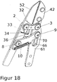
- the counter-cutting lever 41 forms the basis for a flat four-bar linkage and carries a first joint 2, via which the lever lever 51 forming the drive lever with the Counter-cutting lever 41 is pivotally connected, and a second joint 3, via which a lever formed by a lever lever second lever 61 is pivotally connected to the counter cutting lever 41.
- the crank lever 61 has a slot guide in the form of a link 62 which extends along the crank lever in the longitudinal direction with a slight curvature and at its ends bearing shell-shaped extensions, the detent recesses 65, 66 form, as in particular FIG. 5 can be seen.
- the link 62 is formed on the knife edge 52 opposite side of the second joint 3 in the crank lever 61.
- the handle tubes comprise according to the Figures 1 and 2 a first lever tube 43, which is connected via an end collar 44 with the free end of the counter-blade lever 41 and carries a handle 49.
- a second lever tube 63 is connected to the gate lever 61 via a final collar 64 with the free end of the crank lever 61 and carries a handle 69th
- the knife lever 51 is connected to the crank lever 61 via a coupling 70, wherein a first end of the coupling 70 via a third joint 8 is pivotally connected to the blade lever 51 at the knife edge 52 opposite side of the first joint 2 and at a distance from this.
- the second end of the coupling 70 is articulated via a fourth joint 9 and slidably connected in the link 62 of the link lever 61 thereto.
- the planar four-bar linkage formed in this way with the joints 2, 3 and 8, 9 has a reduction ratio which depends on the distance between the second joint 3 and the fourth joint 9 and thus on the position of this fourth joint in the link 62, which is displaceable in this scenery.
- the movement of the crank lever 61 is transmitted via the coupling 70 on the knife lever 51.
- the coupling 70 is connected in the joint 9 with the crank lever 61.
- the hinge 9 formed by a hinge pin with a head 91 is rotatable and displaceable in the link 62 and can assume different slide positions during operation of the scissors.
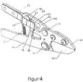
- a leaf spring 11 is fixed on the side facing away from the cutting elements 42, 52 side of the slot guide of the crank lever 61 relative thereto and has partially over the slot guide 62 extending bent portions 12, 13, 14. These bent portions form a recess 14 formed for receiving a head 91 of the hinge pin of the hinge 9 and an inclined sliding surface 13, which together form a normal section latching device for the hinge pin in a first position for the normal section.
- the leaf spring 11 exercises with its sliding surface 13 on the head 91 of the hinge pin of the joint 9, a tactile elastic holding force against displacement of this hinge pin from his in FIG. 4 shown first position at the end remote from the joint 3 end of the slot guide 62 with the cutter head of the scissors out.
- a lying at the free end of the leaf spring 11 section 12 is biased against the crank lever 61.
- the free end edge of this section 12 of the leaf spring 11 forms a force-cutting latching device and prevented in the resting on the crank lever state a return movement of the head 91 of the hinge pin of the joint 9 to the first position, when in the joint 3 adjacent position ( FIG. 9 ) corresponding to a force-cut position.
- FIG. 5 the individual positions of the fourth hinge 9 forming hinge pin in the gate 62 of the crank lever 61 are shown in detail.
- FIGS. 4 and 11 It can be seen that at the end of a movement of the blade 52 in the direction of the counter-blade 42, the Aushebeschräge 46 on the inner edge of the counter-blade lever 41, the end portion 12 of the leaf spring 11 against its bias on the angled spring tab 18 of the crank lever 61 lifts. Between the free end portion 12 of the leaf spring 11 and the crank lever 61 thus creates a gap. During the opening operation of the scissors, the Aushebeschräge 46 moves away from the angled spring tab 18. The bias of the leaf spring 11 is selected so that the free end portion 12 of the leaf spring rests in the position shown with pressure on the crank lever 61.
- the tension spring 10 reaches in this gear constellation their greatest bias and calls on the coupling 70 a corresponding restoring moment forth, however, the first counteracts the force-locking device in the form of the free edge of the end portion 12 of the leaf spring 11.
- the hinge pin of the joint 9 moves out of the support shell and along the support edge 64 in the in FIG. 5 shown position P5.
- the head 91 has already pushed slightly below the end portion 12 of the leaf spring 11 in this position, so that the leaf spring 11 can no longer block the further movement of the hinge pin, even after the Aushebeschräge 46 again in the further course of the opening operation of the spring tab 18th has moved away.
- the function of the embodiment described so far is as follows: The operator decides with the selected opening width of the handle tubes 49, 69 on the desired force potential. The by the edge 63 of the gate 62 after FIG. 5 and the sliding surface 13 resulting tactile stop signals the operator the maximum opening width of the handle tubes for the normal section. For cutting a thick branch, the operator opens the handle tubes beyond the stop to the maximum opening width of the handle tubes.
- the largest transmission ratio of the scissors is available, without the user has to perform a separate switching movement of a transmission, or even take the scissors for extension of telescopic handle tubes from the hand. The switching operation is possible even if the cutting operation has been started in the normal setting, but the operator then notices that the branch to be cut is too thick or too resistant for this gear setting.
- the scissors can be easily opened up to the maximum power section setting and the cutting process can be ended as a force cut.
- the gear automatically returns to normal cutting.
- FIG. 14 shows the scissors after a completed force incision.
- the free end of the leaf spring 11 is raised and has no locking action on the condyle 91. If the scissors for the next cut opened again, the joint 91 automatically jumps back into the joint position P1.
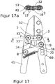
- FIG. 17 a reinforcing tab 32 is shown with integrated spring tab 33, with the help of which it is avoided that in a horizontal working position of the scissors according to FIG. 15 , the hinge pin of the joint 9 remains when opening the scissors in the bearing shell 65.
- the spring tab 33 has on its rear side a Reibbuckel 34, which prevents too easy relative movement of the blade lever 51 with respect to the counter cutting lever 41 and thus achieves the same effect as the diaphragm spring described above.
- At least one (not shown) plate spring can be used, which biases the hinge pin of the joint 2 in the axial direction.
- FIG. 17 It can also be seen how the displacement of the actuating lever 23 by means of a recess 35 in the counter cutting lever 41 and a stop pin 36 which is pressed into the adjusting lever 23 is limited.
Landscapes
- Life Sciences & Earth Sciences (AREA)
- Forests & Forestry (AREA)
- Biodiversity & Conservation Biology (AREA)
- Ecology (AREA)
- Environmental Sciences (AREA)
- Engineering & Computer Science (AREA)
- Mechanical Engineering (AREA)
- Scissors And Nippers (AREA)
Applications Claiming Priority (1)
| Application Number | Priority Date | Filing Date | Title |
|---|---|---|---|
| DE102017009982.0A DE102017009982A1 (de) | 2017-10-26 | 2017-10-26 | Handschere, insbesondere Ast-, Hecken- und/oder Gartenschere |
Publications (2)
| Publication Number | Publication Date |
|---|---|
| EP3476205A1 true EP3476205A1 (fr) | 2019-05-01 |
| EP3476205B1 EP3476205B1 (fr) | 2020-12-02 |
Family
ID=64082834
Family Applications (1)
| Application Number | Title | Priority Date | Filing Date |
|---|---|---|---|
| EP18000837.7A Active EP3476205B1 (fr) | 2017-10-26 | 2018-10-26 | Cisailles à main, en particulier un sécateur, cisailles à haies et/ou de jardinage |
Country Status (2)
| Country | Link |
|---|---|
| EP (1) | EP3476205B1 (fr) |
| DE (1) | DE102017009982A1 (fr) |
Cited By (2)
| Publication number | Priority date | Publication date | Assignee | Title |
|---|---|---|---|---|
| CN110340945A (zh) * | 2019-06-27 | 2019-10-18 | 北京大学第三医院(北京大学第三临床医学院) | 一种组织破碎剪 |
| US20220346326A1 (en) * | 2021-04-29 | 2022-11-03 | Techtronic Cordless Gp | Hand tool with shear assembly |
Citations (3)
| Publication number | Priority date | Publication date | Assignee | Title |
|---|---|---|---|---|
| EP0421108B1 (fr) | 1989-09-08 | 1994-10-05 | WOLF-Geräte GmbH Vertriebsgesellschaft KG | Cisailles à main, en particulier sécateur, cisailles à haies et/ou de jardinage |
| CN202524796U (zh) * | 2012-03-13 | 2012-11-14 | 中山庆琏金属制品有限公司 | 一种多段可调式树杆剪 |
| DE112014006266T5 (de) * | 2014-01-27 | 2016-10-13 | Thomas Lin | Gartenscheren mit Schnitt-Umschaltmodus |
-
2017
- 2017-10-26 DE DE102017009982.0A patent/DE102017009982A1/de not_active Ceased
-
2018
- 2018-10-26 EP EP18000837.7A patent/EP3476205B1/fr active Active
Patent Citations (3)
| Publication number | Priority date | Publication date | Assignee | Title |
|---|---|---|---|---|
| EP0421108B1 (fr) | 1989-09-08 | 1994-10-05 | WOLF-Geräte GmbH Vertriebsgesellschaft KG | Cisailles à main, en particulier sécateur, cisailles à haies et/ou de jardinage |
| CN202524796U (zh) * | 2012-03-13 | 2012-11-14 | 中山庆琏金属制品有限公司 | 一种多段可调式树杆剪 |
| DE112014006266T5 (de) * | 2014-01-27 | 2016-10-13 | Thomas Lin | Gartenscheren mit Schnitt-Umschaltmodus |
Cited By (4)
| Publication number | Priority date | Publication date | Assignee | Title |
|---|---|---|---|---|
| CN110340945A (zh) * | 2019-06-27 | 2019-10-18 | 北京大学第三医院(北京大学第三临床医学院) | 一种组织破碎剪 |
| CN110340945B (zh) * | 2019-06-27 | 2024-04-09 | 北京大学第三医院(北京大学第三临床医学院) | 一种组织破碎剪 |
| US20220346326A1 (en) * | 2021-04-29 | 2022-11-03 | Techtronic Cordless Gp | Hand tool with shear assembly |
| US12471539B2 (en) | 2021-04-29 | 2025-11-18 | Techtronic Cordless Gp | Hand tool with shear assembly |
Also Published As
| Publication number | Publication date |
|---|---|
| EP3476205B1 (fr) | 2020-12-02 |
| DE102017009982A1 (de) | 2019-05-02 |
Similar Documents
| Publication | Publication Date | Title |
|---|---|---|
| EP0421108B1 (fr) | Cisailles à main, en particulier sécateur, cisailles à haies et/ou de jardinage | |
| DE2552787C3 (de) | Gelenkbeschlag für Sitze, insbesondere Fahrzeugsitze | |
| EP2549851B1 (fr) | Cisaille actionnée manuellement | |
| WO2007107227A2 (fr) | Instrument chirurgical | |
| EP2979538B1 (fr) | Secateur | |
| DE1553692A1 (de) | Baumschere | |
| EP1625784B1 (fr) | Outil de coupe manuel, en particulier un taille-haie ou sécateur | |
| WO2015177032A1 (fr) | Dispositif de commutation | |
| EP2007553A1 (fr) | Outil à main à ouverture automatique | |
| DE3523058C2 (de) | Laengsverstellbare sicherheits-skibindung | |
| DE69918041T2 (de) | Skibindung | |
| EP3476205B1 (fr) | Cisailles à main, en particulier un sécateur, cisailles à haies et/ou de jardinage | |
| EP2576314B1 (fr) | Dispositif de blocage pour systèmes de manoeuvre d'aiguille | |
| EP1834544A1 (fr) | Verrouillage pour tables de ping-pong dotée de demi-panneaux pivotants | |
| DE3905445A1 (de) | Vorderbacken fuer sicherheitsskibindungen | |
| DE2810903C3 (de) | Überlastsicherung für einen Pflug | |
| DE102016003426A1 (de) | Handgeführtes Arbeitsgerät mit einer Vorrichtung zur Inbetriebnahme eines elektrischen Antriebsmotors | |
| EP3017686A1 (fr) | Tete de coupe, en particulier pour un secateur | |
| DE3419152A1 (de) | Kettenbremsvorrichtung | |
| EP2926746B1 (fr) | Instrument chirurgical | |
| EP0181947B1 (fr) | Roue porteuse oscillante pour charrues-brabant | |
| EP3420793B1 (fr) | Dispositif de réglage de la position d'un longeron d'un appareil déplacable | |
| DE1193291B (de) | Regelvorrichtung fuer hydraulische Kraftheber, insbesondere fuer Schlepper | |
| DE102006002830A1 (de) | Ausstellvorrichtung für den Flügel eines Fensters oder dergleichen | |
| EP3374230B1 (fr) | Dispositif de siège pour un véhicule |
Legal Events
| Date | Code | Title | Description |
|---|---|---|---|
| STAA | Information on the status of an ep patent application or granted ep patent |
Free format text: STATUS: UNKNOWN |
|
| PUAI | Public reference made under article 153(3) epc to a published international application that has entered the european phase |
Free format text: ORIGINAL CODE: 0009012 |
|
| STAA | Information on the status of an ep patent application or granted ep patent |
Free format text: STATUS: THE APPLICATION HAS BEEN PUBLISHED |
|
| AK | Designated contracting states |
Kind code of ref document: A1 Designated state(s): AL AT BE BG CH CY CZ DE DK EE ES FI FR GB GR HR HU IE IS IT LI LT LU LV MC MK MT NL NO PL PT RO RS SE SI SK SM TR |
|
| AX | Request for extension of the european patent |
Extension state: BA ME |
|
| 19U | Interruption of proceedings before grant |
Effective date: 20190418 |
|
| 19W | Proceedings resumed before grant after interruption of proceedings |
Effective date: 20191202 |
|
| STAA | Information on the status of an ep patent application or granted ep patent |
Free format text: STATUS: REQUEST FOR EXAMINATION WAS MADE |
|
| 17P | Request for examination filed |
Effective date: 20191017 |
|
| RBV | Designated contracting states (corrected) |
Designated state(s): AL AT BE BG CH CY CZ DE DK EE ES FI FR GB GR HR HU IE IS IT LI LT LU LV MC MK MT NL NO PL PT RO RS SE SI SK SM TR |
|
| GRAP | Despatch of communication of intention to grant a patent |
Free format text: ORIGINAL CODE: EPIDOSNIGR1 |
|
| STAA | Information on the status of an ep patent application or granted ep patent |
Free format text: STATUS: GRANT OF PATENT IS INTENDED |
|
| INTG | Intention to grant announced |
Effective date: 20200616 |
|
| GRAS | Grant fee paid |
Free format text: ORIGINAL CODE: EPIDOSNIGR3 |
|
| GRAA | (expected) grant |
Free format text: ORIGINAL CODE: 0009210 |
|
| STAA | Information on the status of an ep patent application or granted ep patent |
Free format text: STATUS: THE PATENT HAS BEEN GRANTED |
|
| AK | Designated contracting states |
Kind code of ref document: B1 Designated state(s): AL AT BE BG CH CY CZ DE DK EE ES FI FR GB GR HR HU IE IS IT LI LT LU LV MC MK MT NL NO PL PT RO RS SE SI SK SM TR |
|
| REG | Reference to a national code |
Ref country code: GB Ref legal event code: FG4D Free format text: NOT ENGLISH |
|
| REG | Reference to a national code |
Ref country code: AT Ref legal event code: REF Ref document number: 1339842 Country of ref document: AT Kind code of ref document: T Effective date: 20201215 Ref country code: CH Ref legal event code: EP |
|
| REG | Reference to a national code |
Ref country code: DE Ref legal event code: R096 Ref document number: 502018003145 Country of ref document: DE |
|
| REG | Reference to a national code |
Ref country code: IE Ref legal event code: FG4D Free format text: LANGUAGE OF EP DOCUMENT: GERMAN |
|
| PG25 | Lapsed in a contracting state [announced via postgrant information from national office to epo] |
Ref country code: RS Free format text: LAPSE BECAUSE OF FAILURE TO SUBMIT A TRANSLATION OF THE DESCRIPTION OR TO PAY THE FEE WITHIN THE PRESCRIBED TIME-LIMIT Effective date: 20201202 Ref country code: FI Free format text: LAPSE BECAUSE OF FAILURE TO SUBMIT A TRANSLATION OF THE DESCRIPTION OR TO PAY THE FEE WITHIN THE PRESCRIBED TIME-LIMIT Effective date: 20201202 Ref country code: GR Free format text: LAPSE BECAUSE OF FAILURE TO SUBMIT A TRANSLATION OF THE DESCRIPTION OR TO PAY THE FEE WITHIN THE PRESCRIBED TIME-LIMIT Effective date: 20210303 Ref country code: NO Free format text: LAPSE BECAUSE OF FAILURE TO SUBMIT A TRANSLATION OF THE DESCRIPTION OR TO PAY THE FEE WITHIN THE PRESCRIBED TIME-LIMIT Effective date: 20210302 |
|
| REG | Reference to a national code |
Ref country code: NL Ref legal event code: MP Effective date: 20201202 |
|
| PG25 | Lapsed in a contracting state [announced via postgrant information from national office to epo] |
Ref country code: BG Free format text: LAPSE BECAUSE OF FAILURE TO SUBMIT A TRANSLATION OF THE DESCRIPTION OR TO PAY THE FEE WITHIN THE PRESCRIBED TIME-LIMIT Effective date: 20210302 Ref country code: PL Free format text: LAPSE BECAUSE OF FAILURE TO SUBMIT A TRANSLATION OF THE DESCRIPTION OR TO PAY THE FEE WITHIN THE PRESCRIBED TIME-LIMIT Effective date: 20201202 Ref country code: LV Free format text: LAPSE BECAUSE OF FAILURE TO SUBMIT A TRANSLATION OF THE DESCRIPTION OR TO PAY THE FEE WITHIN THE PRESCRIBED TIME-LIMIT Effective date: 20201202 Ref country code: SE Free format text: LAPSE BECAUSE OF FAILURE TO SUBMIT A TRANSLATION OF THE DESCRIPTION OR TO PAY THE FEE WITHIN THE PRESCRIBED TIME-LIMIT Effective date: 20201202 |
|
| PG25 | Lapsed in a contracting state [announced via postgrant information from national office to epo] |
Ref country code: NL Free format text: LAPSE BECAUSE OF FAILURE TO SUBMIT A TRANSLATION OF THE DESCRIPTION OR TO PAY THE FEE WITHIN THE PRESCRIBED TIME-LIMIT Effective date: 20201202 Ref country code: HR Free format text: LAPSE BECAUSE OF FAILURE TO SUBMIT A TRANSLATION OF THE DESCRIPTION OR TO PAY THE FEE WITHIN THE PRESCRIBED TIME-LIMIT Effective date: 20201202 |
|
| REG | Reference to a national code |
Ref country code: LT Ref legal event code: MG9D |
|
| PG25 | Lapsed in a contracting state [announced via postgrant information from national office to epo] |
Ref country code: SM Free format text: LAPSE BECAUSE OF FAILURE TO SUBMIT A TRANSLATION OF THE DESCRIPTION OR TO PAY THE FEE WITHIN THE PRESCRIBED TIME-LIMIT Effective date: 20201202 Ref country code: LT Free format text: LAPSE BECAUSE OF FAILURE TO SUBMIT A TRANSLATION OF THE DESCRIPTION OR TO PAY THE FEE WITHIN THE PRESCRIBED TIME-LIMIT Effective date: 20201202 Ref country code: CZ Free format text: LAPSE BECAUSE OF FAILURE TO SUBMIT A TRANSLATION OF THE DESCRIPTION OR TO PAY THE FEE WITHIN THE PRESCRIBED TIME-LIMIT Effective date: 20201202 Ref country code: EE Free format text: LAPSE BECAUSE OF FAILURE TO SUBMIT A TRANSLATION OF THE DESCRIPTION OR TO PAY THE FEE WITHIN THE PRESCRIBED TIME-LIMIT Effective date: 20201202 Ref country code: RO Free format text: LAPSE BECAUSE OF FAILURE TO SUBMIT A TRANSLATION OF THE DESCRIPTION OR TO PAY THE FEE WITHIN THE PRESCRIBED TIME-LIMIT Effective date: 20201202 Ref country code: SK Free format text: LAPSE BECAUSE OF FAILURE TO SUBMIT A TRANSLATION OF THE DESCRIPTION OR TO PAY THE FEE WITHIN THE PRESCRIBED TIME-LIMIT Effective date: 20201202 Ref country code: PT Free format text: LAPSE BECAUSE OF FAILURE TO SUBMIT A TRANSLATION OF THE DESCRIPTION OR TO PAY THE FEE WITHIN THE PRESCRIBED TIME-LIMIT Effective date: 20210405 |
|
| REG | Reference to a national code |
Ref country code: DE Ref legal event code: R097 Ref document number: 502018003145 Country of ref document: DE |
|
| PG25 | Lapsed in a contracting state [announced via postgrant information from national office to epo] |
Ref country code: IS Free format text: LAPSE BECAUSE OF FAILURE TO SUBMIT A TRANSLATION OF THE DESCRIPTION OR TO PAY THE FEE WITHIN THE PRESCRIBED TIME-LIMIT Effective date: 20210402 |
|
| PLBE | No opposition filed within time limit |
Free format text: ORIGINAL CODE: 0009261 |
|
| STAA | Information on the status of an ep patent application or granted ep patent |
Free format text: STATUS: NO OPPOSITION FILED WITHIN TIME LIMIT |
|
| PG25 | Lapsed in a contracting state [announced via postgrant information from national office to epo] |
Ref country code: IT Free format text: LAPSE BECAUSE OF FAILURE TO SUBMIT A TRANSLATION OF THE DESCRIPTION OR TO PAY THE FEE WITHIN THE PRESCRIBED TIME-LIMIT Effective date: 20201202 Ref country code: AL Free format text: LAPSE BECAUSE OF FAILURE TO SUBMIT A TRANSLATION OF THE DESCRIPTION OR TO PAY THE FEE WITHIN THE PRESCRIBED TIME-LIMIT Effective date: 20201202 |
|
| 26N | No opposition filed |
Effective date: 20210903 |
|
| PG25 | Lapsed in a contracting state [announced via postgrant information from national office to epo] |
Ref country code: DK Free format text: LAPSE BECAUSE OF FAILURE TO SUBMIT A TRANSLATION OF THE DESCRIPTION OR TO PAY THE FEE WITHIN THE PRESCRIBED TIME-LIMIT Effective date: 20201202 Ref country code: SI Free format text: LAPSE BECAUSE OF FAILURE TO SUBMIT A TRANSLATION OF THE DESCRIPTION OR TO PAY THE FEE WITHIN THE PRESCRIBED TIME-LIMIT Effective date: 20201202 |
|
| PG25 | Lapsed in a contracting state [announced via postgrant information from national office to epo] |
Ref country code: ES Free format text: LAPSE BECAUSE OF FAILURE TO SUBMIT A TRANSLATION OF THE DESCRIPTION OR TO PAY THE FEE WITHIN THE PRESCRIBED TIME-LIMIT Effective date: 20201202 |
|
| REG | Reference to a national code |
Ref country code: DE Ref legal event code: R082 Ref document number: 502018003145 Country of ref document: DE Representative=s name: BIRD & BIRD LLP, DE |
|
| REG | Reference to a national code |
Ref country code: CH Ref legal event code: PL |
|
| PG25 | Lapsed in a contracting state [announced via postgrant information from national office to epo] |
Ref country code: IS Free format text: LAPSE BECAUSE OF FAILURE TO SUBMIT A TRANSLATION OF THE DESCRIPTION OR TO PAY THE FEE WITHIN THE PRESCRIBED TIME-LIMIT Effective date: 20210402 |
|
| REG | Reference to a national code |
Ref country code: BE Ref legal event code: MM Effective date: 20211031 |
|
| PG25 | Lapsed in a contracting state [announced via postgrant information from national office to epo] |
Ref country code: MC Free format text: LAPSE BECAUSE OF FAILURE TO SUBMIT A TRANSLATION OF THE DESCRIPTION OR TO PAY THE FEE WITHIN THE PRESCRIBED TIME-LIMIT Effective date: 20201202 |
|
| PG25 | Lapsed in a contracting state [announced via postgrant information from national office to epo] |
Ref country code: LU Free format text: LAPSE BECAUSE OF NON-PAYMENT OF DUE FEES Effective date: 20211026 Ref country code: BE Free format text: LAPSE BECAUSE OF NON-PAYMENT OF DUE FEES Effective date: 20211031 |
|
| PG25 | Lapsed in a contracting state [announced via postgrant information from national office to epo] |
Ref country code: LI Free format text: LAPSE BECAUSE OF NON-PAYMENT OF DUE FEES Effective date: 20211031 Ref country code: CH Free format text: LAPSE BECAUSE OF NON-PAYMENT OF DUE FEES Effective date: 20211031 |
|
| PG25 | Lapsed in a contracting state [announced via postgrant information from national office to epo] |
Ref country code: IE Free format text: LAPSE BECAUSE OF NON-PAYMENT OF DUE FEES Effective date: 20211026 |
|
| PGFP | Annual fee paid to national office [announced via postgrant information from national office to epo] |
Ref country code: FR Payment date: 20221123 Year of fee payment: 5 |
|
| PG25 | Lapsed in a contracting state [announced via postgrant information from national office to epo] |
Ref country code: CY Free format text: LAPSE BECAUSE OF FAILURE TO SUBMIT A TRANSLATION OF THE DESCRIPTION OR TO PAY THE FEE WITHIN THE PRESCRIBED TIME-LIMIT Effective date: 20201202 |
|
| PG25 | Lapsed in a contracting state [announced via postgrant information from national office to epo] |
Ref country code: HU Free format text: LAPSE BECAUSE OF FAILURE TO SUBMIT A TRANSLATION OF THE DESCRIPTION OR TO PAY THE FEE WITHIN THE PRESCRIBED TIME-LIMIT; INVALID AB INITIO Effective date: 20181026 |
|
| P01 | Opt-out of the competence of the unified patent court (upc) registered |
Effective date: 20230912 |
|
| PG25 | Lapsed in a contracting state [announced via postgrant information from national office to epo] |
Ref country code: MK Free format text: LAPSE BECAUSE OF FAILURE TO SUBMIT A TRANSLATION OF THE DESCRIPTION OR TO PAY THE FEE WITHIN THE PRESCRIBED TIME-LIMIT Effective date: 20201202 |
|
| PG25 | Lapsed in a contracting state [announced via postgrant information from national office to epo] |
Ref country code: FR Free format text: LAPSE BECAUSE OF NON-PAYMENT OF DUE FEES Effective date: 20231031 |
|
| PG25 | Lapsed in a contracting state [announced via postgrant information from national office to epo] |
Ref country code: MT Free format text: LAPSE BECAUSE OF FAILURE TO SUBMIT A TRANSLATION OF THE DESCRIPTION OR TO PAY THE FEE WITHIN THE PRESCRIBED TIME-LIMIT Effective date: 20201202 |
|
| REG | Reference to a national code |
Ref country code: AT Ref legal event code: MM01 Ref document number: 1339842 Country of ref document: AT Kind code of ref document: T Effective date: 20231026 |
|
| PG25 | Lapsed in a contracting state [announced via postgrant information from national office to epo] |
Ref country code: AT Free format text: LAPSE BECAUSE OF NON-PAYMENT OF DUE FEES Effective date: 20231026 |
|
| PG25 | Lapsed in a contracting state [announced via postgrant information from national office to epo] |
Ref country code: AT Free format text: LAPSE BECAUSE OF NON-PAYMENT OF DUE FEES Effective date: 20231026 |
|
| PG25 | Lapsed in a contracting state [announced via postgrant information from national office to epo] |
Ref country code: TR Free format text: LAPSE BECAUSE OF FAILURE TO SUBMIT A TRANSLATION OF THE DESCRIPTION OR TO PAY THE FEE WITHIN THE PRESCRIBED TIME-LIMIT Effective date: 20201202 |
|
| PGFP | Annual fee paid to national office [announced via postgrant information from national office to epo] |
Ref country code: DE Payment date: 20251020 Year of fee payment: 8 |
|
| PGFP | Annual fee paid to national office [announced via postgrant information from national office to epo] |
Ref country code: GB Payment date: 20251024 Year of fee payment: 8 |
|
| PGFP | Annual fee paid to national office [announced via postgrant information from national office to epo] |
Ref country code: AT Payment date: 20260410 Year of fee payment: 5 |