EP3477236A1 - Caloduc et procédé de fabrication d'un caloduc - Google Patents
Caloduc et procédé de fabrication d'un caloduc Download PDFInfo
- Publication number
- EP3477236A1 EP3477236A1 EP18202198.0A EP18202198A EP3477236A1 EP 3477236 A1 EP3477236 A1 EP 3477236A1 EP 18202198 A EP18202198 A EP 18202198A EP 3477236 A1 EP3477236 A1 EP 3477236A1
- Authority
- EP
- European Patent Office
- Prior art keywords
- inlet
- metal layers
- porous body
- heat pipe
- working fluid
- Prior art date
- Legal status (The legal status is an assumption and is not a legal conclusion. Google has not performed a legal analysis and makes no representation as to the accuracy of the status listed.)
- Granted
Links
Images


Classifications
-
- F—MECHANICAL ENGINEERING; LIGHTING; HEATING; WEAPONS; BLASTING
- F28—HEAT EXCHANGE IN GENERAL
- F28D—HEAT-EXCHANGE APPARATUS, NOT PROVIDED FOR IN ANOTHER SUBCLASS, IN WHICH THE HEAT-EXCHANGE MEDIA DO NOT COME INTO DIRECT CONTACT
- F28D15/00—Heat-exchange apparatus with the intermediate heat-transfer medium in closed tubes passing into or through the conduit walls ; Heat-exchange apparatus employing intermediate heat-transfer medium or bodies
- F28D15/02—Heat-exchange apparatus with the intermediate heat-transfer medium in closed tubes passing into or through the conduit walls ; Heat-exchange apparatus employing intermediate heat-transfer medium or bodies in which the medium condenses and evaporates, e.g. heat pipes
- F28D15/0283—Means for filling or sealing heat pipes
-
- B—PERFORMING OPERATIONS; TRANSPORTING
- B23—MACHINE TOOLS; METAL-WORKING NOT OTHERWISE PROVIDED FOR
- B23P—METAL-WORKING NOT OTHERWISE PROVIDED FOR; COMBINED OPERATIONS; UNIVERSAL MACHINE TOOLS
- B23P15/00—Making specific metal objects by operations not covered by a single other subclass or a group in this subclass
- B23P15/26—Making specific metal objects by operations not covered by a single other subclass or a group in this subclass heat exchangers or the like
-
- F—MECHANICAL ENGINEERING; LIGHTING; HEATING; WEAPONS; BLASTING
- F28—HEAT EXCHANGE IN GENERAL
- F28D—HEAT-EXCHANGE APPARATUS, NOT PROVIDED FOR IN ANOTHER SUBCLASS, IN WHICH THE HEAT-EXCHANGE MEDIA DO NOT COME INTO DIRECT CONTACT
- F28D15/00—Heat-exchange apparatus with the intermediate heat-transfer medium in closed tubes passing into or through the conduit walls ; Heat-exchange apparatus employing intermediate heat-transfer medium or bodies
- F28D15/02—Heat-exchange apparatus with the intermediate heat-transfer medium in closed tubes passing into or through the conduit walls ; Heat-exchange apparatus employing intermediate heat-transfer medium or bodies in which the medium condenses and evaporates, e.g. heat pipes
- F28D15/0233—Heat-exchange apparatus with the intermediate heat-transfer medium in closed tubes passing into or through the conduit walls ; Heat-exchange apparatus employing intermediate heat-transfer medium or bodies in which the medium condenses and evaporates, e.g. heat pipes the conduits having a particular shape, e.g. non-circular cross-section, annular
-
- F—MECHANICAL ENGINEERING; LIGHTING; HEATING; WEAPONS; BLASTING
- F28—HEAT EXCHANGE IN GENERAL
- F28F—DETAILS OF HEAT-EXCHANGE AND HEAT-TRANSFER APPARATUS, OF GENERAL APPLICATION
- F28F3/00—Plate-like or laminated elements; Assemblies of plate-like or laminated elements
- F28F3/08—Elements constructed for building-up into stacks, e.g. capable of being taken apart for cleaning
-
- G—PHYSICS
- G06—COMPUTING OR CALCULATING; COUNTING
- G06F—ELECTRIC DIGITAL DATA PROCESSING
- G06F1/00—Details not covered by groups G06F3/00 - G06F13/00 and G06F21/00
- G06F1/16—Constructional details or arrangements
- G06F1/20—Cooling means
- G06F1/203—Cooling means for portable computers, e.g. for laptops
-
- H—ELECTRICITY
- H05—ELECTRIC TECHNIQUES NOT OTHERWISE PROVIDED FOR
- H05K—PRINTED CIRCUITS; CASINGS OR CONSTRUCTIONAL DETAILS OF ELECTRIC APPARATUS; MANUFACTURE OF ASSEMBLAGES OF ELECTRICAL COMPONENTS
- H05K7/00—Constructional details common to different types of electric apparatus
- H05K7/20—Modifications to facilitate cooling, ventilating, or heating
- H05K7/2029—Modifications to facilitate cooling, ventilating, or heating using a liquid coolant with phase change in electronic enclosures
- H05K7/20336—Heat pipes, e.g. wicks or capillary pumps
-
- H—ELECTRICITY
- H10—SEMICONDUCTOR DEVICES; ELECTRIC SOLID-STATE DEVICES NOT OTHERWISE PROVIDED FOR
- H10W—GENERIC PACKAGES, INTERCONNECTIONS, CONNECTORS OR OTHER CONSTRUCTIONAL DETAILS OF DEVICES COVERED BY CLASS H10
- H10W40/00—Arrangements for thermal protection or thermal control
- H10W40/70—Fillings or auxiliary members in containers or in encapsulations for thermal protection or control
- H10W40/73—Fillings or auxiliary members in containers or in encapsulations for thermal protection or control for cooling by change of state
-
- B—PERFORMING OPERATIONS; TRANSPORTING
- B23—MACHINE TOOLS; METAL-WORKING NOT OTHERWISE PROVIDED FOR
- B23P—METAL-WORKING NOT OTHERWISE PROVIDED FOR; COMBINED OPERATIONS; UNIVERSAL MACHINE TOOLS
- B23P2700/00—Indexing scheme relating to the articles being treated, e.g. manufactured, repaired, assembled, connected or other operations covered in the subgroups
- B23P2700/09—Heat pipes
-
- F—MECHANICAL ENGINEERING; LIGHTING; HEATING; WEAPONS; BLASTING
- F28—HEAT EXCHANGE IN GENERAL
- F28D—HEAT-EXCHANGE APPARATUS, NOT PROVIDED FOR IN ANOTHER SUBCLASS, IN WHICH THE HEAT-EXCHANGE MEDIA DO NOT COME INTO DIRECT CONTACT
- F28D15/00—Heat-exchange apparatus with the intermediate heat-transfer medium in closed tubes passing into or through the conduit walls ; Heat-exchange apparatus employing intermediate heat-transfer medium or bodies
- F28D15/02—Heat-exchange apparatus with the intermediate heat-transfer medium in closed tubes passing into or through the conduit walls ; Heat-exchange apparatus employing intermediate heat-transfer medium or bodies in which the medium condenses and evaporates, e.g. heat pipes
- F28D15/0266—Heat-exchange apparatus with the intermediate heat-transfer medium in closed tubes passing into or through the conduit walls ; Heat-exchange apparatus employing intermediate heat-transfer medium or bodies in which the medium condenses and evaporates, e.g. heat pipes with separate evaporating and condensing chambers connected by at least one conduit; Loop-type heat pipes; with multiple or common evaporating or condensing chambers
-
- F—MECHANICAL ENGINEERING; LIGHTING; HEATING; WEAPONS; BLASTING
- F28—HEAT EXCHANGE IN GENERAL
- F28F—DETAILS OF HEAT-EXCHANGE AND HEAT-TRANSFER APPARATUS, OF GENERAL APPLICATION
- F28F2230/00—Sealing means
-
- G—PHYSICS
- G06—COMPUTING OR CALCULATING; COUNTING
- G06F—ELECTRIC DIGITAL DATA PROCESSING
- G06F2200/00—Indexing scheme relating to G06F1/04 - G06F1/32
- G06F2200/20—Indexing scheme relating to G06F1/20
- G06F2200/201—Cooling arrangements using cooling fluid
Definitions
- This disclosure relates to a heat pipe and a method for manufacturing the heat pipe.
- a heat pipe that uses the phase transition of a working fluid is a device that cools a heat-generating component such as a semiconductor device (e.g., central processing unit (CPU)) installed in an electronic device.
- the heat pipe includes an inlet port through which the working fluid is injected into the heat pipe. After the heat pipe is filled with the working fluid, the end of the inlet port is sealed (refer to Japanese Patent No. 6146484 ).
- a heat pipe in accordance with one embodiment includes an inlet through which a working fluid is injected.
- the inlet includes a non-sealed portion and a sealed portion connected to the non-sealed portion.
- the non-sealed portion and the sealed portion each include two outermost metal layers and a plurality of intermediate metal layers stacked between the outermost metal layers.
- the heat pipe further includes a porous body arranged in the inlet.
- a heat pipe in accordance with a further embodiment includes a hermetically sealed inlet through which a working fluid is injected.
- the inlet includes a non-sealed portion and a sealed portion connected to the non-sealed portion.
- the non-sealed portion and the sealed portion each include two outermost metal layers and a plurality of intermediate metal layers stacked between the outermost metal layers.
- the heat pipe further includes a porous body sandwiched between the two outermost metal layers.
- a method for manufacturing a heat pipe in accordance with another embodiment includes stacking a plurality of metal layers to form an inlet through which a working fluid is injected.
- the metal layers include two outermost metal layers and a plurality of intermediate metal layers stacked between the outermost metal layers.
- the method further includes arranging a porous body in the inlet, and forming a sealed portion by injecting the working fluid through the porous body into the heat pipe and then pressing and flattening the outermost metal layers and the intermediate metal layers in a stacking direction so as to hermetically seal the inlet.
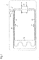
- a loop heat pipe 11 is accommodated in, for example, a mobile electronic device 12 such as a smartphone or a tablet.
- the loop heat pipe 11 (simply referred to as the heat pipe 11) includes an evaporator 21, an evaporation pipe 22, a condenser 23, a liquid pipe 24, and an inlet 25.
- the evaporator 21 is connected by the evaporation pipe 22 to the condenser 23, and the condenser 23 is connected by the liquid pipe 24 to the evaporator 21.
- the evaporator 21 functions to vaporize a working fluid C and generate vapor Cv.
- the vapor Cv of the working fluid C flows through the evaporation pipe 22 to the condenser 23.
- the condenser 23 functions to liquefy the vapor of the working fluid C.
- the liquefied working fluid C flows through the liquid pipe 24 to the evaporator 21.
- the evaporator 21, the evaporation pipe 22, the condenser 23, and the liquid pipe 24 form a flow passage 26 configuring a loop through which the liquefied working fluid C or the vapor Cv flows.
- the evaporator 21 is fixed to a heat-generating component in contact with the heat-generating component.
- the evaporator 21 includes, for example, four through holes 21X. Bolts are inserted through the through holes 21X to fix the evaporator 21 to a circuit board or the like on which the heat-generating component is mounted.
- the evaporator 21 uses the heat generated by the heat-generating component to vaporize the working fluid C into the vapor Cv.
- the vapor Cv generated in the evaporator 21 is guided through the evaporation pipe 22 to the condenser 23 and liquefied in the condenser 23. This transfers the heat of the heat generation component to the condenser 23 and limits increases in the temperature of the heat-generating component. From the condenser 23, the liquefied working fluid C is guided through the liquid pipe 24 to the evaporator 21.
- a fluid having a high vapor pressure and a large latent heat of vaporization is used as the working fluid C.
- the use of such a working fluid C efficiently cools the heat-generating component with the latent heat of vaporization.
- the working fluid C may be, for example, ammonia, water, fluorocarbon, alcohol, or acetone.
- the inlet 25 serves as an entrance for the working fluid C when filling the heat pipe 11 with the working fluid C.
- the inlet 25 is connected to the liquid pipe 24.
- the inlet 25 is hermetically sealed after injecting the working fluid C.
- the inlet 25 may also be connected to the condenser 23, the evaporation pipe 22, or the evaporator 21. In this case, the injected working fluid C moves from the injected location into the liquid pipe 24.
- the inlet 25 includes a non-sealed portion 31 that is connected to the liquid pipe 24 and a sealed portion 32 that is connected to the non-sealed portion 31.
- the shape of the non-sealed portion 31 is substantially maintained before and after the inlet 25 is sealed. That is, the shape of the non-sealed portion 31 after the inlet 25 is sealed is substantially the same as the shape of the non-sealed portion 31 when injecting the working fluid C into the liquid pipe 24.
- the sealed portion 32 has the same shape as the non-sealed portion 31 when injecting the working liquid C into the liquid pipe 24. After the liquid pipe 24 is filled with the working fluid C, the sealed portion 32 is squeezed and flattened to hermetically seal the inlet 25 so that the working fluid C does not leak out of the liquid pipe 24.
- the heat pipe 11 may be constructed by, for example, stacking a plurality of metal layers.
- the metal layers are, for example, copper layers having superior thermal conductivity and directly bonded to one another through solid-state welding.
- the metal layers each have a thickness of, for example, approximately 50 ⁇ m to 200 ⁇ m.
- the metal layers are not limited to copper layers and may be stainless layers, aluminum layers, or magnesium layers. Further, there is particularly no limit to the number of metal layers.
- the material of one or more of the stacked metal layers may differ from the material of the other metal layers.
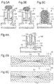
- Figs. 2A and 2B illustrate a state prior to sealing off of the inlet 25.
- Fig. 2A is a plan view illustrating one example of the inlet 25, and
- Fig. 2B is a cross-sectional view taken along line A-A in Fig. 2A .
- the heat pipe 11 may be formed by metal layers 61 to 66. Among the metal layers 61 to 66, the uppermost metal layer 66 is removed in Fig. 2A .
- the inlet 25 includes an inlet port 40 and a porous body 50 arranged in the inlet port 40.
- the inlet port 40 may be constructed by, for example, sequentially stacking the outermost metal layer 61, the intermediate metal layers 62 to 65, and the outermost metal layer 66. In the description hereafter, the outermost metal layers will not be distinguished from the intermediate metal layers when there is no need to do so.
- the inlet port 40 may be formed integrally with the liquid pipe 24 and the like.
- the metal layers 61 to 66 are indicated in solid lines and hatched differently. However, for example, when the metal layers 61 to 66 are integrated through diffusion bonding, the interfaces of the metal layers 61 to 66 may be eliminated. Thus, boundaries will not be clear. The same applies to the interfaces and boundaries in the structure subsequent to sealing and in the structures of modified examples described below.
- the outermost metal layers 61 and 66 are located at the outermost sides of the stacked metal layers constructing the inlet port 40 and respectively correspond to the lowermost metal layer and the uppermost metal layer.
- the intermediate metal layers 62 to 65 are located between the outermost metal layer 61 and the outermost metal layer 66.
- the outermost metal layers 61 and 66 are each solid and do not include holes or grooves. The outermost metal layers 61 and 66 form parts of the outer walls of the inlet port 40.
- the intermediate metal layer 62 includes substantially parallel wall portions 62a and 62b spaced apart by a given distance in a widthwise direction (left-right direction in Fig. 2B ).
- the intermediate layers 63, 64, and 65 respectively include substantially parallel wall portions 63a, 63b, 64a, 64b, 65a, and 65b spaced apart by the given distance.
- the wall portions 62a to 65a and 62b to 65b of the intermediate metal layers 62 to 65 form parts of the outer walls of the inlet port 40.
- the liquid pipe 24, which defines the flow passage 26 has a wall 24a including an opening 24x in the vicinity of the inlet port 40.
- the inlet port 40 includes an inlet passage 41 formed by the metal layers 61 to 66.
- the inlet passage 41 has a width X that is the distance from the wall portions 62a to 65a to the wall portions 62b to 65b in the intermediate metal layers 62 to 65.
- the width X of the inlet passage 41 is larger than a width Y of the opening 24x.
- the wall 24a of the liquid pipe 24 includes ends 24p determining the width Y of the opening 24x.
- Each end 24p projects into the inlet passage 41 from the wall portions 62a to 65a and 62b to 65b of the intermediate metal layers 62 to 65 in the inlet port 40.
- the ends 24p of the wall 24a of the liquid pipe 24 avoid unnecessary entrance of the porous body 50 into the flow passage of the liquid pipe 24.
- the ends 24p may be referred to as the protrusions.
- the inlet passage 41 is formed by the outermost metal layers 61 and 66 and the wall portions 62a to 65a and 62b to 65b of the intermediate metal layers 62 to 65.
- the working fluid C is injected through the inlet passage 41 into the liquid pipe 24.
- the porous body 50 is arranged in the inlet port 40.
- interior of the inlet port 40 namely, the inlet passage 41 is filled with the porous body 50.
- the porous body 50 is a structure including pores.
- a metal fiber sheet non-woven cloth of metal fibers
- the metal used in the porous body 50 may be, for example, copper, copper alloy, stainless steel, aluminum, magnesium alloy, or the like.
- the sealed portion 32 is formed by squeezing and flattening the outermost metal layers 61 and 66, the intermediate metal layers 62 to 65, and the porous body 50, which are illustrated in Figs. 2A and 2B , in the vertical direction of Fig. 3 (i.e., stacking direction).
- the sealed portion 32 may be formed through, for example, ultrasonic welding. Ultrasonic welding applies ultrasonic waves to welded subjects to pressurize and bond the welded subjects. To accelerate the welding, the welded subjects may be heated.
- the squeezed porous body 50 is sandwiched between the outermost metal layers 61 and 66. Even when gaps are formed within the porous body 50 or between the porous body 50 and the metal layers 61 to 66, hermetic sealing is established as long as the gaps do not connect the flow passage 26 and the outside of the heat pipe 11.
- the present embodiment has the advantage described below.
- the heat pipe 11 includes the inlet 25 through which the working fluid C is injected.
- the inlet 25 includes the inlet port 40, through which the working fluid C is injected into the heat pipe 11, and the porous body 50, which is arranged in the inlet port 40.
- the porous body 50 includes pores. The pores produce capillary force acting on the working fluid C.
- the working fluid C is smoothly guided by the porous body 50 from the outside of the heat pipe 11 to the inside of the inlet port 40.
- the working fluid C is moved by the porous body 50 in the inlet port 40 and drawn from the opening 24x of the liquid pipe 24 into the liquid pipe 24. In this manner, the arrangement of the porous body 50 in the inlet port 40 smoothly injects the working fluid C into the heat pipe 11.
- inlet 25 inlet port 40 and porous body 50
- inlet port 40 and porous body 50 The construction of the inlet 25 (inlet port 40 and porous body 50) may be changed.
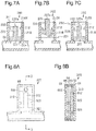
- an inlet 100 includes an inlet port 110 and a porous body 120.
- the porous body 120 includes a support portion 121 and a drawing portion 122.
- the inlet port 110 includes an inlet passage 111 having the width X.
- the support portion 121 extends in the widthwise direction of the inlet 100 and has the same width as the width X of the inlet passage 111.
- the drawing portion 122 extends from the support portion 121 toward an opening 110X of the inlet port 110.
- the support portion 121 and the drawing portion 122 are arranged so that the porous body 120 is T-shaped in a plan view as illustrated in Fig. 4A .
- the drawing portion 122 has a width that is set to be smaller than the width X of the inlet passage 111 (width of opening 110X).
- the drawing portion 122 has a thickness (height) that is smaller than the height of the inlet passage 111.
- the support portion 121 has a thickness (height) that is smaller than the height of the inlet passage 111.
- the weight of the support portion 121 and the drawing portion 122 spaces the support portion 121 and the drawing portion 122 apart from the outermost metal layer 66 (uppermost metal layer as viewed in Fig. 4C ), which forms the outer wall of the inlet port 110.
- the drawing portion 122 is spaced apart from the wall portions 62a to 65a and 62b to 65b of the intermediate metal layers 62 to 65.
- the support portion 121 is spaced apart from the wall portions 64a, 65a, 64b, and 65b of the intermediate metal layers 64 and 65.
- the porous body 120 (support 121 and drawing portion 122) is movable along the inlet passage 111.
- the inlet port 110 includes projections 112 located closer to the opening 110X than the support portion 121.
- the projections 112 project from opposite wall portions of the inlet port 110 toward the drawing portion 122.
- a width Z between the two projections 112 is smaller than the width X of the inlet passage 111.
- the projections 112 are formed at locations where a distal end of the porous body 120, that is, a distal end 122a of the drawing portion 122, projects out of the opening 110X of the inlet port 110 when the support portion 121 comes into contact with the projection 112. In this manner, the projection of the distal end 122a of the drawing portion 122 out of the opening 110X of the inlet port 110 facilitates the injection of the working fluid C. This will be described with reference to Figs. 5A to 5C .
- the working fluid C is injected in a state in which the distal end 122a of the drawing portion 122 is projected out of the opening 110X.
- the working fluid C easily collects on the distal end 122a of the drawing portion 122 projecting out of the opening 110X.
- the capillary force produced by the pores of the porous body 120 draws the working fluid C to the inlet passage 111 of the inlet port 110.
- this fills the inlet passage 111 with the working fluid C.
- the working fluid C moves from the inlet passage 111 into the liquid pipe 24. In this manner, the injection of the working fluid C is facilitated.
- the porous body 120 is movable along the inlet passage 111 of the inlet port 110. This allows the sealed portion to be set in accordance with the position of the porous body 120. That is, the sealed portion may be set at a position where the porous body 120 is present or at a position where the porous body 120 is not present. This will now be described in further detail with reference to Figs. 6A to 6C .
- Fig. 6A indicates two potential sealing positions 131 and 132 with single-dashed lines.
- the porous body 120 is present at the sealing position 131.
- portions of the inlet 100 excluding the sealing position 131 (and vicinity of sealing position 131) may be set as the non-sealed portion.
- the flattened sealed portion (sealing position 131) of the inlet 100 includes the porous body 120 sandwiched between the outermost metal layers 61 and 66.
- the porous body 120 is not present at the sealing position 132 illustrated in Fig. 6A .
- portions of the inlet 100 excluding the sealing position 132 may be set as the non-sealed portion.
- the inlet 100 is sealed at the sealing position 132.
- the outermost metal layers 61 and 66 are directly bonded to each other. Further, the porous body 120 is not sandwiched between the outermost metal layers 61 and 66.
- solid-state welding such as ultrasonic welding may be performed to hermetically seal the inlet 100.
- the welding subjects be formed from the same material.
- the sealing positions 131 and 132 may both be set as the sealed portion.
- the location of the sealed portion is not limited to the sealing positions 131 and 132.
- the location where the drawing portion 122 of the porous body 120 is squeezed may be set as the sealed portion.
- the material of the inlet port 110 does not have to be the same as the material of the porous body 120.
- the inlet 100 is hermetically sealed at, for example, the sealing position 132 illustrated in Fig. 6A .
- Figs. 7A to 7C illustrate another modified example of an inlet 200.
- the inlet 200 includes an inlet port 210 and a porous body 220.
- the porous body 220 includes a support portion 221 and a drawing portion 222.
- the porous body 220 (support portion 221 and drawing portion 222) is movable along the inlet 200 (inlet passage 211) between a projected position of Fig. 7B and a retreated position of Fig. 7C .
- the porous body 220 may be shorter than the inlet port 210 (inlet passage 211). In this case, when the porous body 220 is at the retreated position of Fig.
- the inlet port 210 includes projections 212 formed in the same manner as the projections 112 of Fig. 4A .
- Fig. 7B when the porous body 220 is at the projected position, that is, when the support portion 221 of the porous body 220 comes into contact with the projections 212 of the inlet port 210, the distal end portion 222a of the drawing portion 222 projects out of the opening 210X of the inlet port 210. This allows for easy injection of the working fluid C as described above with reference to Figs. 5A to 5C .
- a sealing position 231 may be set at a sealed portion where the inlet 200 is sealed in a state in which the distal end portion 222a of the drawing portion 222 projects out of the opening 210X of the inlet port 210.
- portions of the inlet 200 excluding the sealing position 231 (and vicinity of sealing position 231) may be set as the non-sealed portion.
- a sealing position 232 may be set at a sealed portion where the inlet 200 is sealed in a state in which the distal end portion 222a of the drawing portion 222 is retracted into the inlet port 210 and located inward from the opening 210X.
- portions of the inlet 200 excluding the sealing position 232 may be set as the non-sealed portion.
- the porous body 220 is not present at each of the sealing positions 231 and 232. Accordingly, as described with reference to Fig. 6C , the outermost metal layers 61 and 66, which are of the same material, are directly welded to each other. Thus, the material of the porous body 220 may differ from the material of the inlet port 210. That is, the porous body 220 may be formed from any material.
- Figs. 8A and 8B illustrate a further modified example of an inlet 300.
- the inlet 300 includes an inlet port 310 and a porous body 320.
- Fig. 8B is a cross-sectional view taken along line D-D in Fig. 8A .
- the porous body 320 includes a support portion 321 and a drawing portion 322.
- the inlet port 310 includes an opening 66X in the outermost metal layer 66 of the inlet port 310.
- the working fluid C is injected from the opening 66X.
- Figs. 9A and 9B illustrate a further modified example of an inlet 400.
- the inlet 400 includes the inlet port 110 and a porous body 420.
- Fig. 9B is a cross-sectional view taken along line E-E in Fig. 9A .
- the porous body 420 includes a support portion 421 and a drawing portion 422.
- the drawing portion 420 includes two distal end portions 422a and 422b.
- the distal end portions 422a and 422b are arranged on opposite wall portions of the inlet passage 111 in the inlet port 110.
- the porous body 420 is movable along the inlet passage 111.
- the distal end portions 422a and 422b are projectable out of the opening 110X of the inlet port 110.
- the projection of the distal end portions 422a and 422b out of the opening 110X allows the working fluid C to be further easily drawn into the porous body 420. This further facilities the injection of the working fluid C.
- Figs. 10A and 10B illustrate a further modified example of an inlet 500.
- the inlet 500 includes the inlet port 110 and a porous body 520.
- Fig. 10B is a cross-sectional view taken along line F-F in Fig. 10A .
- the porous body 520 includes a support portion 521 and a drawing portion 522.
- the drawing portion 522 includes three distal end portions 522a, 522b, and 522c.
- the distal end portions 522a and 522c are arranged on opposite wall portions of the inlet passage 111 in the inlet port 110.
- the porous body 520 is movable along the inlet passage 111.
- the distal end portions 522a to 522c are projectable out of the opening 110X of the inlet port 110.
- the projection of the distal end portions 522a to 522c out of the opening 110X allows the working fluid C to be further easily drawn into the porous body 520. This further facilitates the injection of the
- the inlets 25, 100, 200, 300, 400, and 500 in each of the above embodiments may be applied to a heat pipe other than a loop heat pipe.
- the inlets 25, 100, 200, 300, 400, and 500 may be applied to a flat heat pipe.
Landscapes
- Engineering & Computer Science (AREA)
- Physics & Mathematics (AREA)
- General Engineering & Computer Science (AREA)
- Mechanical Engineering (AREA)
- Thermal Sciences (AREA)
- Theoretical Computer Science (AREA)
- Sustainable Development (AREA)
- Life Sciences & Earth Sciences (AREA)
- Microelectronics & Electronic Packaging (AREA)
- Computer Hardware Design (AREA)
- Human Computer Interaction (AREA)
- General Physics & Mathematics (AREA)
- Cooling Or The Like Of Electrical Apparatus (AREA)
- Cooling Or The Like Of Semiconductors Or Solid State Devices (AREA)
Applications Claiming Priority (1)
| Application Number | Priority Date | Filing Date | Title |
|---|---|---|---|
| JP2017207518A JP6893160B2 (ja) | 2017-10-26 | 2017-10-26 | ヒートパイプ、ヒートパイプの製造方法 |
Publications (2)
| Publication Number | Publication Date |
|---|---|
| EP3477236A1 true EP3477236A1 (fr) | 2019-05-01 |
| EP3477236B1 EP3477236B1 (fr) | 2020-03-11 |
Family
ID=63965450
Family Applications (1)
| Application Number | Title | Priority Date | Filing Date |
|---|---|---|---|
| EP18202198.0A Active EP3477236B1 (fr) | 2017-10-26 | 2018-10-24 | Caloduc et procédé de fabrication d'un caloduc |
Country Status (4)
| Country | Link |
|---|---|
| US (1) | US10859321B2 (fr) |
| EP (1) | EP3477236B1 (fr) |
| JP (1) | JP6893160B2 (fr) |
| CN (1) | CN109708499B (fr) |
Cited By (1)
| Publication number | Priority date | Publication date | Assignee | Title |
|---|---|---|---|---|
| EP4276401A1 (fr) * | 2022-05-12 | 2023-11-15 | Shinko Electric Industries Co., Ltd. | Caloduc |
Families Citing this family (3)
| Publication number | Priority date | Publication date | Assignee | Title |
|---|---|---|---|---|
| TWI658776B (zh) * | 2017-11-27 | 2019-05-01 | 宏碁股份有限公司 | 電子裝置的散熱系統 |
| JP7028659B2 (ja) * | 2018-01-30 | 2022-03-02 | 新光電気工業株式会社 | ループ型ヒートパイプ、ループ型ヒートパイプの製造方法 |
| JP7635360B2 (ja) * | 2021-02-26 | 2025-02-25 | 京セラ株式会社 | 熱デバイス |
Citations (2)
| Publication number | Priority date | Publication date | Assignee | Title |
|---|---|---|---|---|
| JPS6146484B2 (fr) | 1981-07-20 | 1986-10-14 | Ppg Industries Inc | |
| US20160259383A1 (en) * | 2013-12-13 | 2016-09-08 | Fujitsu Limited | Loop heat pipe, method of manufacturing the same, and electronic device |
Family Cites Families (19)
| Publication number | Priority date | Publication date | Assignee | Title |
|---|---|---|---|---|
| US3397648A (en) * | 1967-04-17 | 1968-08-20 | Gomco Surgical Mfg Corp | Suction pump |
| JPS5222457B2 (fr) * | 1974-02-15 | 1977-06-17 | ||
| EP0108552A3 (fr) * | 1982-10-30 | 1986-09-10 | Kabushiki Kaisha Toshiba | Appareil d'amenée de gaz respiratoires vers un analyseur |
| JPS6170389A (ja) * | 1985-09-10 | 1986-04-11 | Toshiba Corp | ヒートパイプの封じ切り方法 |
| JPH0631704B2 (ja) * | 1986-07-02 | 1994-04-27 | 株式会社日立製作所 | ヒ−トパイプ |
| TW327672B (en) * | 1995-10-05 | 1998-03-01 | Babcock & Wilcox Co | Field serviceable fill tube for use on heat pipes |
| TW577969B (en) * | 2003-07-21 | 2004-03-01 | Arro Superconducting Technolog | Vapor/liquid separated heat exchanging device |
| US20050028965A1 (en) * | 2003-08-07 | 2005-02-10 | Ching-Chih Chen | Combined structure of a thermal chamber and a thermal tower |
| CN100573019C (zh) * | 2006-03-03 | 2009-12-23 | 富准精密工业(深圳)有限公司 | 热管 |
| JP2008047573A (ja) * | 2006-08-11 | 2008-02-28 | Matsushita Electric Ind Co Ltd | 樹脂封止型半導体装置の製造装置、樹脂封止型半導体装置の製造方法、および樹脂封止型半導体装置 |
| US7866178B2 (en) * | 2007-07-24 | 2011-01-11 | Asia Vital Components Co., Ltd. | Device and method for vacuum-sealing a cooling medium |
| US20090178784A1 (en) * | 2008-01-15 | 2009-07-16 | Chin-Wen Wang | Manufacturing Method of Isothermal Vapor Chamber And Product Thereof |
| JP4683080B2 (ja) * | 2008-07-10 | 2011-05-11 | ソニー株式会社 | 熱輸送デバイス、電子機器、封入装置及び熱輸送デバイスの製造方法 |
| JP2010048535A (ja) * | 2008-08-25 | 2010-03-04 | Denso Corp | ヒートパイプ装置及びそれを備えた排気熱回収装置 |
| JP2010243077A (ja) * | 2009-04-07 | 2010-10-28 | Sony Corp | 熱輸送デバイスの製造方法、熱輸送デバイス、電子機器及びカシメピン |
| JP2010286134A (ja) * | 2009-06-09 | 2010-12-24 | Sony Corp | 熱輸送デバイスの製造方法及び熱輸送デバイス |
| KR101201808B1 (ko) * | 2010-06-03 | 2012-11-15 | 삼성에스디아이 주식회사 | 이차 전지 및 이차 전지의 전해액 주입 방법 |
| JP5769989B2 (ja) * | 2011-03-09 | 2015-08-26 | 株式会社ジャパンディスプレイ | 表示装置 |
| CN105974096B (zh) * | 2016-07-27 | 2018-07-20 | 北京瑞莱博石油技术有限公司 | 岩心流体饱和度耐压测量装置 |
-
2017
- 2017-10-26 JP JP2017207518A patent/JP6893160B2/ja active Active
-
2018
- 2018-09-27 US US16/143,659 patent/US10859321B2/en active Active
- 2018-10-16 CN CN201811202650.9A patent/CN109708499B/zh active Active
- 2018-10-24 EP EP18202198.0A patent/EP3477236B1/fr active Active
Patent Citations (2)
| Publication number | Priority date | Publication date | Assignee | Title |
|---|---|---|---|---|
| JPS6146484B2 (fr) | 1981-07-20 | 1986-10-14 | Ppg Industries Inc | |
| US20160259383A1 (en) * | 2013-12-13 | 2016-09-08 | Fujitsu Limited | Loop heat pipe, method of manufacturing the same, and electronic device |
Cited By (2)
| Publication number | Priority date | Publication date | Assignee | Title |
|---|---|---|---|---|
| EP4276401A1 (fr) * | 2022-05-12 | 2023-11-15 | Shinko Electric Industries Co., Ltd. | Caloduc |
| US12498180B2 (en) | 2022-05-12 | 2025-12-16 | Shinko Electric Industries Co., Ltd. | Heat pipe |
Also Published As
| Publication number | Publication date |
|---|---|
| JP6893160B2 (ja) | 2021-06-23 |
| JP2019078507A (ja) | 2019-05-23 |
| CN109708499A (zh) | 2019-05-03 |
| US10859321B2 (en) | 2020-12-08 |
| US20190128618A1 (en) | 2019-05-02 |
| EP3477236B1 (fr) | 2020-03-11 |
| CN109708499B (zh) | 2022-05-24 |
Similar Documents
| Publication | Publication Date | Title |
|---|---|---|
| US11131509B2 (en) | Loop heat pipe | |
| US11789505B2 (en) | Loop heat pipe | |
| EP3477236B1 (fr) | Caloduc et procédé de fabrication d'un caloduc | |
| US10859319B2 (en) | Loop heat pipe | |
| US10876799B2 (en) | Loop heat pipe | |
| US10420253B2 (en) | Loop heat pipe, manufacturing method thereof, and electronic device | |
| US11118843B2 (en) | Heat pipe | |
| US11507155B2 (en) | Heat pipe with support post | |
| JP6691467B2 (ja) | ループ型ヒートパイプ及びその製造方法 | |
| CN110030856B (zh) | 一种环路热管及其制造方法 | |
| US11262137B2 (en) | Loop-type heat pipe | |
| JP7236825B2 (ja) | ループ型ヒートパイプ及びその製造方法 | |
| US11774181B2 (en) | Loop heat pipe with recessed top or bottom surface | |
| EP3428565A1 (fr) | Caloduc en boucle et procédé de fabrication d'un caloduc en boucle | |
| CN111954789A (zh) | 均热板 | |
| US11719490B2 (en) | Loop heat pipe with recessed outer wall surface | |
| JP2019082309A (ja) | ループ型ヒートパイプ、及びループ型ヒートパイプ製造方法 | |
| US11808521B2 (en) | Loop heat pipe | |
| US11774182B2 (en) | Loop heat pipe |
Legal Events
| Date | Code | Title | Description |
|---|---|---|---|
| PUAI | Public reference made under article 153(3) epc to a published international application that has entered the european phase |
Free format text: ORIGINAL CODE: 0009012 |
|
| STAA | Information on the status of an ep patent application or granted ep patent |
Free format text: STATUS: THE APPLICATION HAS BEEN PUBLISHED |
|
| AK | Designated contracting states |
Kind code of ref document: A1 Designated state(s): AL AT BE BG CH CY CZ DE DK EE ES FI FR GB GR HR HU IE IS IT LI LT LU LV MC MK MT NL NO PL PT RO RS SE SI SK SM TR |
|
| AX | Request for extension of the european patent |
Extension state: BA ME |
|
| STAA | Information on the status of an ep patent application or granted ep patent |
Free format text: STATUS: REQUEST FOR EXAMINATION WAS MADE |
|
| 17P | Request for examination filed |
Effective date: 20190717 |
|
| RBV | Designated contracting states (corrected) |
Designated state(s): AL AT BE BG CH CY CZ DE DK EE ES FI FR GB GR HR HU IE IS IT LI LT LU LV MC MK MT NL NO PL PT RO RS SE SI SK SM TR |
|
| RIC1 | Information provided on ipc code assigned before grant |
Ipc: H01L 23/427 20060101ALI20190816BHEP Ipc: F28D 15/02 20060101AFI20190816BHEP Ipc: G06F 1/20 20060101ALI20190816BHEP |
|
| GRAP | Despatch of communication of intention to grant a patent |
Free format text: ORIGINAL CODE: EPIDOSNIGR1 |
|
| STAA | Information on the status of an ep patent application or granted ep patent |
Free format text: STATUS: GRANT OF PATENT IS INTENDED |
|
| INTG | Intention to grant announced |
Effective date: 20191004 |
|
| GRAS | Grant fee paid |
Free format text: ORIGINAL CODE: EPIDOSNIGR3 |
|
| GRAA | (expected) grant |
Free format text: ORIGINAL CODE: 0009210 |
|
| STAA | Information on the status of an ep patent application or granted ep patent |
Free format text: STATUS: THE PATENT HAS BEEN GRANTED |
|
| AK | Designated contracting states |
Kind code of ref document: B1 Designated state(s): AL AT BE BG CH CY CZ DE DK EE ES FI FR GB GR HR HU IE IS IT LI LT LU LV MC MK MT NL NO PL PT RO RS SE SI SK SM TR |
|
| REG | Reference to a national code |
Ref country code: GB Ref legal event code: FG4D |
|
| REG | Reference to a national code |
Ref country code: CH Ref legal event code: EP |
|
| REG | Reference to a national code |
Ref country code: AT Ref legal event code: REF Ref document number: 1243658 Country of ref document: AT Kind code of ref document: T Effective date: 20200315 |
|
| REG | Reference to a national code |
Ref country code: IE Ref legal event code: FG4D |
|
| REG | Reference to a national code |
Ref country code: DE Ref legal event code: R096 Ref document number: 602018003003 Country of ref document: DE |
|
| PG25 | Lapsed in a contracting state [announced via postgrant information from national office to epo] |
Ref country code: NO Free format text: LAPSE BECAUSE OF FAILURE TO SUBMIT A TRANSLATION OF THE DESCRIPTION OR TO PAY THE FEE WITHIN THE PRESCRIBED TIME-LIMIT Effective date: 20200611 Ref country code: FI Free format text: LAPSE BECAUSE OF FAILURE TO SUBMIT A TRANSLATION OF THE DESCRIPTION OR TO PAY THE FEE WITHIN THE PRESCRIBED TIME-LIMIT Effective date: 20200311 Ref country code: RS Free format text: LAPSE BECAUSE OF FAILURE TO SUBMIT A TRANSLATION OF THE DESCRIPTION OR TO PAY THE FEE WITHIN THE PRESCRIBED TIME-LIMIT Effective date: 20200311 |
|
| REG | Reference to a national code |
Ref country code: NL Ref legal event code: MP Effective date: 20200311 |
|
| PG25 | Lapsed in a contracting state [announced via postgrant information from national office to epo] |
Ref country code: LV Free format text: LAPSE BECAUSE OF FAILURE TO SUBMIT A TRANSLATION OF THE DESCRIPTION OR TO PAY THE FEE WITHIN THE PRESCRIBED TIME-LIMIT Effective date: 20200311 Ref country code: SE Free format text: LAPSE BECAUSE OF FAILURE TO SUBMIT A TRANSLATION OF THE DESCRIPTION OR TO PAY THE FEE WITHIN THE PRESCRIBED TIME-LIMIT Effective date: 20200311 Ref country code: GR Free format text: LAPSE BECAUSE OF FAILURE TO SUBMIT A TRANSLATION OF THE DESCRIPTION OR TO PAY THE FEE WITHIN THE PRESCRIBED TIME-LIMIT Effective date: 20200612 Ref country code: HR Free format text: LAPSE BECAUSE OF FAILURE TO SUBMIT A TRANSLATION OF THE DESCRIPTION OR TO PAY THE FEE WITHIN THE PRESCRIBED TIME-LIMIT Effective date: 20200311 Ref country code: BG Free format text: LAPSE BECAUSE OF FAILURE TO SUBMIT A TRANSLATION OF THE DESCRIPTION OR TO PAY THE FEE WITHIN THE PRESCRIBED TIME-LIMIT Effective date: 20200611 |
|
| REG | Reference to a national code |
Ref country code: LT Ref legal event code: MG4D |
|
| PG25 | Lapsed in a contracting state [announced via postgrant information from national office to epo] |
Ref country code: NL Free format text: LAPSE BECAUSE OF FAILURE TO SUBMIT A TRANSLATION OF THE DESCRIPTION OR TO PAY THE FEE WITHIN THE PRESCRIBED TIME-LIMIT Effective date: 20200311 |
|
| PG25 | Lapsed in a contracting state [announced via postgrant information from national office to epo] |
Ref country code: LT Free format text: LAPSE BECAUSE OF FAILURE TO SUBMIT A TRANSLATION OF THE DESCRIPTION OR TO PAY THE FEE WITHIN THE PRESCRIBED TIME-LIMIT Effective date: 20200311 Ref country code: SM Free format text: LAPSE BECAUSE OF FAILURE TO SUBMIT A TRANSLATION OF THE DESCRIPTION OR TO PAY THE FEE WITHIN THE PRESCRIBED TIME-LIMIT Effective date: 20200311 Ref country code: CZ Free format text: LAPSE BECAUSE OF FAILURE TO SUBMIT A TRANSLATION OF THE DESCRIPTION OR TO PAY THE FEE WITHIN THE PRESCRIBED TIME-LIMIT Effective date: 20200311 Ref country code: EE Free format text: LAPSE BECAUSE OF FAILURE TO SUBMIT A TRANSLATION OF THE DESCRIPTION OR TO PAY THE FEE WITHIN THE PRESCRIBED TIME-LIMIT Effective date: 20200311 Ref country code: RO Free format text: LAPSE BECAUSE OF FAILURE TO SUBMIT A TRANSLATION OF THE DESCRIPTION OR TO PAY THE FEE WITHIN THE PRESCRIBED TIME-LIMIT Effective date: 20200311 Ref country code: IS Free format text: LAPSE BECAUSE OF FAILURE TO SUBMIT A TRANSLATION OF THE DESCRIPTION OR TO PAY THE FEE WITHIN THE PRESCRIBED TIME-LIMIT Effective date: 20200711 Ref country code: SK Free format text: LAPSE BECAUSE OF FAILURE TO SUBMIT A TRANSLATION OF THE DESCRIPTION OR TO PAY THE FEE WITHIN THE PRESCRIBED TIME-LIMIT Effective date: 20200311 Ref country code: PT Free format text: LAPSE BECAUSE OF FAILURE TO SUBMIT A TRANSLATION OF THE DESCRIPTION OR TO PAY THE FEE WITHIN THE PRESCRIBED TIME-LIMIT Effective date: 20200805 |
|
| REG | Reference to a national code |
Ref country code: AT Ref legal event code: MK05 Ref document number: 1243658 Country of ref document: AT Kind code of ref document: T Effective date: 20200311 |
|
| REG | Reference to a national code |
Ref country code: DE Ref legal event code: R097 Ref document number: 602018003003 Country of ref document: DE |
|
| PLBE | No opposition filed within time limit |
Free format text: ORIGINAL CODE: 0009261 |
|
| STAA | Information on the status of an ep patent application or granted ep patent |
Free format text: STATUS: NO OPPOSITION FILED WITHIN TIME LIMIT |
|
| PG25 | Lapsed in a contracting state [announced via postgrant information from national office to epo] |
Ref country code: IT Free format text: LAPSE BECAUSE OF FAILURE TO SUBMIT A TRANSLATION OF THE DESCRIPTION OR TO PAY THE FEE WITHIN THE PRESCRIBED TIME-LIMIT Effective date: 20200311 Ref country code: ES Free format text: LAPSE BECAUSE OF FAILURE TO SUBMIT A TRANSLATION OF THE DESCRIPTION OR TO PAY THE FEE WITHIN THE PRESCRIBED TIME-LIMIT Effective date: 20200311 Ref country code: AT Free format text: LAPSE BECAUSE OF FAILURE TO SUBMIT A TRANSLATION OF THE DESCRIPTION OR TO PAY THE FEE WITHIN THE PRESCRIBED TIME-LIMIT Effective date: 20200311 Ref country code: DK Free format text: LAPSE BECAUSE OF FAILURE TO SUBMIT A TRANSLATION OF THE DESCRIPTION OR TO PAY THE FEE WITHIN THE PRESCRIBED TIME-LIMIT Effective date: 20200311 |
|
| 26N | No opposition filed |
Effective date: 20201214 |
|
| PG25 | Lapsed in a contracting state [announced via postgrant information from national office to epo] |
Ref country code: PL Free format text: LAPSE BECAUSE OF FAILURE TO SUBMIT A TRANSLATION OF THE DESCRIPTION OR TO PAY THE FEE WITHIN THE PRESCRIBED TIME-LIMIT Effective date: 20200311 Ref country code: SI Free format text: LAPSE BECAUSE OF FAILURE TO SUBMIT A TRANSLATION OF THE DESCRIPTION OR TO PAY THE FEE WITHIN THE PRESCRIBED TIME-LIMIT Effective date: 20200311 |
|
| PG25 | Lapsed in a contracting state [announced via postgrant information from national office to epo] |
Ref country code: LU Free format text: LAPSE BECAUSE OF NON-PAYMENT OF DUE FEES Effective date: 20201024 Ref country code: MC Free format text: LAPSE BECAUSE OF FAILURE TO SUBMIT A TRANSLATION OF THE DESCRIPTION OR TO PAY THE FEE WITHIN THE PRESCRIBED TIME-LIMIT Effective date: 20200311 |
|
| REG | Reference to a national code |
Ref country code: BE Ref legal event code: MM Effective date: 20201031 |
|
| PG25 | Lapsed in a contracting state [announced via postgrant information from national office to epo] |
Ref country code: FR Free format text: LAPSE BECAUSE OF NON-PAYMENT OF DUE FEES Effective date: 20201031 |
|
| PG25 | Lapsed in a contracting state [announced via postgrant information from national office to epo] |
Ref country code: BE Free format text: LAPSE BECAUSE OF NON-PAYMENT OF DUE FEES Effective date: 20201031 |
|
| PG25 | Lapsed in a contracting state [announced via postgrant information from national office to epo] |
Ref country code: IE Free format text: LAPSE BECAUSE OF NON-PAYMENT OF DUE FEES Effective date: 20201024 |
|
| REG | Reference to a national code |
Ref country code: CH Ref legal event code: PL |
|
| PG25 | Lapsed in a contracting state [announced via postgrant information from national office to epo] |
Ref country code: TR Free format text: LAPSE BECAUSE OF FAILURE TO SUBMIT A TRANSLATION OF THE DESCRIPTION OR TO PAY THE FEE WITHIN THE PRESCRIBED TIME-LIMIT Effective date: 20200311 Ref country code: MT Free format text: LAPSE BECAUSE OF FAILURE TO SUBMIT A TRANSLATION OF THE DESCRIPTION OR TO PAY THE FEE WITHIN THE PRESCRIBED TIME-LIMIT Effective date: 20200311 Ref country code: CY Free format text: LAPSE BECAUSE OF FAILURE TO SUBMIT A TRANSLATION OF THE DESCRIPTION OR TO PAY THE FEE WITHIN THE PRESCRIBED TIME-LIMIT Effective date: 20200311 |
|
| PG25 | Lapsed in a contracting state [announced via postgrant information from national office to epo] |
Ref country code: MK Free format text: LAPSE BECAUSE OF FAILURE TO SUBMIT A TRANSLATION OF THE DESCRIPTION OR TO PAY THE FEE WITHIN THE PRESCRIBED TIME-LIMIT Effective date: 20200311 Ref country code: AL Free format text: LAPSE BECAUSE OF FAILURE TO SUBMIT A TRANSLATION OF THE DESCRIPTION OR TO PAY THE FEE WITHIN THE PRESCRIBED TIME-LIMIT Effective date: 20200311 |
|
| PG25 | Lapsed in a contracting state [announced via postgrant information from national office to epo] |
Ref country code: LI Free format text: LAPSE BECAUSE OF NON-PAYMENT OF DUE FEES Effective date: 20211031 Ref country code: CH Free format text: LAPSE BECAUSE OF NON-PAYMENT OF DUE FEES Effective date: 20211031 |
|
| GBPC | Gb: european patent ceased through non-payment of renewal fee |
Effective date: 20221024 |
|
| PG25 | Lapsed in a contracting state [announced via postgrant information from national office to epo] |
Ref country code: GB Free format text: LAPSE BECAUSE OF NON-PAYMENT OF DUE FEES Effective date: 20221024 |
|
| PGFP | Annual fee paid to national office [announced via postgrant information from national office to epo] |
Ref country code: DE Payment date: 20240828 Year of fee payment: 7 |