EP3477249B1 - Procédé de reconnaissance de forme d'un objet dans une zone extérieure d'un véhicule automobile et véhicule automobile - Google Patents
Procédé de reconnaissance de forme d'un objet dans une zone extérieure d'un véhicule automobile et véhicule automobile Download PDFInfo
- Publication number
- EP3477249B1 EP3477249B1 EP18194225.1A EP18194225A EP3477249B1 EP 3477249 B1 EP3477249 B1 EP 3477249B1 EP 18194225 A EP18194225 A EP 18194225A EP 3477249 B1 EP3477249 B1 EP 3477249B1
- Authority
- EP
- European Patent Office
- Prior art keywords
- motor vehicle
- scan line
- image
- height
- profile
- Prior art date
- Legal status (The legal status is an assumption and is not a legal conclusion. Google has not performed a legal analysis and makes no representation as to the accuracy of the status listed.)
- Active
Links
Images


Classifications
-
- B—PERFORMING OPERATIONS; TRANSPORTING
- B60—VEHICLES IN GENERAL
- B60D—VEHICLE CONNECTIONS
- B60D1/00—Traction couplings; Hitches; Draw-gear; Towing devices
- B60D1/24—Traction couplings; Hitches; Draw-gear; Towing devices characterised by arrangements for particular functions
- B60D1/36—Traction couplings; Hitches; Draw-gear; Towing devices characterised by arrangements for particular functions for facilitating connection, e.g. hitch catchers
-
- B—PERFORMING OPERATIONS; TRANSPORTING
- B60—VEHICLES IN GENERAL
- B60D—VEHICLE CONNECTIONS
- B60D1/00—Traction couplings; Hitches; Draw-gear; Towing devices
- B60D1/58—Auxiliary devices
- B60D1/62—Auxiliary devices involving supply lines, electric circuits or the like
-
- B—PERFORMING OPERATIONS; TRANSPORTING
- B60—VEHICLES IN GENERAL
- B60R—VEHICLES, VEHICLE FITTINGS, OR VEHICLE PARTS, NOT OTHERWISE PROVIDED FOR
- B60R1/00—Optical viewing arrangements; Real-time viewing arrangements for drivers or passengers using optical image capturing systems, e.g. cameras or video systems specially adapted for use in or on vehicles
- B60R1/002—Optical viewing arrangements; Real-time viewing arrangements for drivers or passengers using optical image capturing systems, e.g. cameras or video systems specially adapted for use in or on vehicles specially adapted for covering the peripheral part of the vehicle, e.g. for viewing tyres, bumpers or the like
- B60R1/003—Optical viewing arrangements; Real-time viewing arrangements for drivers or passengers using optical image capturing systems, e.g. cameras or video systems specially adapted for use in or on vehicles specially adapted for covering the peripheral part of the vehicle, e.g. for viewing tyres, bumpers or the like for viewing trailer hitches
-
- G—PHYSICS
- G01—MEASURING; TESTING
- G01B—MEASURING LENGTH, THICKNESS OR SIMILAR LINEAR DIMENSIONS; MEASURING ANGLES; MEASURING AREAS; MEASURING IRREGULARITIES OF SURFACES OR CONTOURS
- G01B11/00—Measuring arrangements characterised by the use of optical techniques
- G01B11/14—Measuring arrangements characterised by the use of optical techniques for measuring distance or clearance between spaced objects or spaced apertures
-
- G—PHYSICS
- G01—MEASURING; TESTING
- G01B—MEASURING LENGTH, THICKNESS OR SIMILAR LINEAR DIMENSIONS; MEASURING ANGLES; MEASURING AREAS; MEASURING IRREGULARITIES OF SURFACES OR CONTOURS
- G01B11/00—Measuring arrangements characterised by the use of optical techniques
- G01B11/24—Measuring arrangements characterised by the use of optical techniques for measuring contours or curvatures
- G01B11/25—Measuring arrangements characterised by the use of optical techniques for measuring contours or curvatures by projecting a pattern, e.g. one or more lines, moiré fringes on the object
-
- G—PHYSICS
- G06—COMPUTING OR CALCULATING; COUNTING
- G06F—ELECTRIC DIGITAL DATA PROCESSING
- G06F18/00—Pattern recognition
- G06F18/20—Analysing
- G06F18/22—Matching criteria, e.g. proximity measures
-
- G—PHYSICS
- G06—COMPUTING OR CALCULATING; COUNTING
- G06T—IMAGE DATA PROCESSING OR GENERATION, IN GENERAL
- G06T7/00—Image analysis
- G06T7/20—Analysis of motion
- G06T7/246—Analysis of motion using feature-based methods, e.g. the tracking of corners or segments
- G06T7/248—Analysis of motion using feature-based methods, e.g. the tracking of corners or segments involving reference images or patches
-
- G—PHYSICS
- G06—COMPUTING OR CALCULATING; COUNTING
- G06T—IMAGE DATA PROCESSING OR GENERATION, IN GENERAL
- G06T7/00—Image analysis
- G06T7/50—Depth or shape recovery
- G06T7/55—Depth or shape recovery from multiple images
-
- G—PHYSICS
- G06—COMPUTING OR CALCULATING; COUNTING
- G06T—IMAGE DATA PROCESSING OR GENERATION, IN GENERAL
- G06T7/00—Image analysis
- G06T7/60—Analysis of geometric attributes
-
- G—PHYSICS
- G06—COMPUTING OR CALCULATING; COUNTING
- G06T—IMAGE DATA PROCESSING OR GENERATION, IN GENERAL
- G06T7/00—Image analysis
- G06T7/70—Determining position or orientation of objects or cameras
- G06T7/73—Determining position or orientation of objects or cameras using feature-based methods
-
- G—PHYSICS
- G06—COMPUTING OR CALCULATING; COUNTING
- G06V—IMAGE OR VIDEO RECOGNITION OR UNDERSTANDING
- G06V20/00—Scenes; Scene-specific elements
- G06V20/50—Context or environment of the image
- G06V20/56—Context or environment of the image exterior to a vehicle by using sensors mounted on the vehicle
-
- B—PERFORMING OPERATIONS; TRANSPORTING
- B60—VEHICLES IN GENERAL
- B60R—VEHICLES, VEHICLE FITTINGS, OR VEHICLE PARTS, NOT OTHERWISE PROVIDED FOR
- B60R2300/00—Details of viewing arrangements using cameras and displays, specially adapted for use in a vehicle
- B60R2300/80—Details of viewing arrangements using cameras and displays, specially adapted for use in a vehicle characterised by the intended use of the viewing arrangement
- B60R2300/808—Details of viewing arrangements using cameras and displays, specially adapted for use in a vehicle characterised by the intended use of the viewing arrangement for facilitating docking to a trailer
-
- G—PHYSICS
- G06—COMPUTING OR CALCULATING; COUNTING
- G06T—IMAGE DATA PROCESSING OR GENERATION, IN GENERAL
- G06T2207/00—Indexing scheme for image analysis or image enhancement
- G06T2207/10—Image acquisition modality
- G06T2207/10016—Video; Image sequence
-
- G—PHYSICS
- G06—COMPUTING OR CALCULATING; COUNTING
- G06T—IMAGE DATA PROCESSING OR GENERATION, IN GENERAL
- G06T2207/00—Indexing scheme for image analysis or image enhancement
- G06T2207/30—Subject of image; Context of image processing
- G06T2207/30248—Vehicle exterior or interior
- G06T2207/30252—Vehicle exterior; Vicinity of vehicle
-
- G—PHYSICS
- G06—COMPUTING OR CALCULATING; COUNTING
- G06T—IMAGE DATA PROCESSING OR GENERATION, IN GENERAL
- G06T2207/00—Indexing scheme for image analysis or image enhancement
- G06T2207/30—Subject of image; Context of image processing
- G06T2207/30248—Vehicle exterior or interior
- G06T2207/30252—Vehicle exterior; Vicinity of vehicle
- G06T2207/30261—Obstacle
-
- G—PHYSICS
- G06—COMPUTING OR CALCULATING; COUNTING
- G06T—IMAGE DATA PROCESSING OR GENERATION, IN GENERAL
- G06T7/00—Image analysis
- G06T7/10—Segmentation; Edge detection
- G06T7/13—Edge detection
-
- G—PHYSICS
- G06—COMPUTING OR CALCULATING; COUNTING
- G06T—IMAGE DATA PROCESSING OR GENERATION, IN GENERAL
- G06T7/00—Image analysis
- G06T7/10—Segmentation; Edge detection
- G06T7/194—Segmentation; Edge detection involving foreground-background segmentation
-
- G—PHYSICS
- G06—COMPUTING OR CALCULATING; COUNTING
- G06T—IMAGE DATA PROCESSING OR GENERATION, IN GENERAL
- G06T7/00—Image analysis
- G06T7/90—Determination of colour characteristics
Definitions
- the invention relates to a method for measuring an object in an exterior area of a motor vehicle.
- the measurement is carried out optically by means of a camera while the motor vehicle is being moved relative to the object.
- the invention also includes a control device for performing the method and a motor vehicle with the control device according to the invention.
- An example of such maneuvering is hitching a trailer to a motor vehicle.
- the spatial position of the trailer coupling must be known.
- a method for recognizing a trailer is known, which is photographed by means of a camera from a motor vehicle, wherein scan lines are defined in the image of the camera, along which a profile (for example a color gradient) is determined, and in the event that a Scan line with a predetermined pattern, which describes a known type of trailer, matches the type of trailer belonging to the pattern is recognized.
- a profile for example a color gradient
- the DE 10 2012 011 121 A1 describes how the parallax effect can be used to distinguish objects with regard to their height with respect to an image recording point.
- the invention is based on the object of recognizing, from a motor vehicle, a shape of an object that is located in an outside area of a motor vehicle.
- the invention provides a method for recognizing the shape of an object in an exterior area of a motor vehicle.
- the method is carried out while the motor vehicle is moving relative to the object.
- a control device of the motor vehicle By means of a control device of the motor vehicle, an image is generated in each case by means of a camera at at least two different measurement times.
- the picture shows the object against a background of the outside area.
- At least one scan line or scan line is defined in a first of the images.
- a scan line is an imaginary line in the image along which pixel values of individual pixels of the image are viewed or analyzed.
- a corresponding scan line is defined for each scan line in each of the other images.
- Each corresponding scan line has the same course in the respective image as the associated scan line of the first image with which it corresponds.
- a corresponding scan line therefore has the same shape as the associated scan line.
- a profile resulting along the scan line is determined for a predetermined image property, for example the pixel brightness or color values of the pixels.
- a resulting corresponding profile is determined along the respective corresponding scan line of every other image.
- Each profile thus describes the respective course of the image property, for example the pixel brightness or the color values of the pixels, along the respective scan line.
- at least one characteristic area of the scan line is determined on the basis of the profile of the scan line.
- a characteristic area is a profile section with a predetermined characteristic shape.
- An example of such a characteristic area can be a maximum or a double peak in the course of the profile.
- Such a characteristic area can be recognized in a corresponding scan line.
- the at least one characteristic area in the respectively corresponding profile is recognized.
- at least one characteristic area of the profile of this scan line is determined for each scan line of the first image and the at least one characteristic area is recognized in the respective corresponding profile by comparing the profile with the respective corresponding profile of every other image. You can now see where the characteristic area is located in the profile and the corresponding profile. You can see how far they are shifted from one another. For each characteristic area of the profile of each scan line, a displacement width of the characteristic area along the respective scan line resulting between the measurement times is then determined.
- the segmentation is carried out here purely optically on the basis of at least two images from the camera.
- the scan lines and the corresponding scan lines have a course which corresponds to an image of a beam which virtually extends three-dimensionally in the outer area at a predetermined height straight away from the motor vehicle.
- This has the advantage that a component of the object that lies on a first specific scan line in the first image comes to rest on a corresponding scan line of another image when the motor vehicle is moving.
- the predetermined height is an expected or known height of the object. This reduces the likelihood that the component will come to lie on different scan lines between two images.
- the invention has the advantage that, on the basis of camera images from a camera, the shape of the object can be recognized without any prior knowledge of the object.
- the method can thus be implemented in a motor vehicle with little additional component outlay and interconnection outlay.
- the invention also encompasses embodiments which result in additional advantages.
- One embodiment provides that, in order to differentiate between the object and the background, a height value is assigned to each characteristic area of the profile of each scan line as a function of its displacement width, and a height profile is thereby generated along each scan line. Based on the respective height profile, a distinction is then made between the object and the background along each scan line. This has the advantage that a surface profile of the object is also determined (height profile in the area of the object).
- the predetermined image property on the basis of which the respective profile is formed along each scan line, comprises a color value and / or a contrast value and / or an edge detection value of an image content of the image.
- an edge detection value can be based on a local derivative can be formed, as it can be formed, for example, as the difference between the brightness values of neighboring pixels of the image.
- those pixels that are arranged along the scan line are used to determine the profile.
- the aforementioned image properties have the advantage that they can be used to distinguish optically between the object and the background.
- the characteristic areas are determined by means of a predetermined feature detection which identifies at least one predetermined, characteristic pattern in the respective profile as a characteristic area.
- a characteristic pattern can be, for example, a local maximum or a local minimum. Provision can also be made to require such a local maximum or local minimum with a predetermined minimum expression, that is to say for example a predetermined minimum height or minimum depth, so that a characteristic area is identified.
- the embodiment has the advantage that at least one characteristic area can be identified automatically in a profile.
- One embodiment provides that straight-ahead travel of the motor vehicle is recognized and the images are generated during straight-ahead travel. This therefore triggers the acquisition of the images at a point in time that is favorable to ensure that characteristic areas arise in the profile which are also contained in each corresponding profile.
- the shape of the scan lines is set as a function of a steering angle of the motor vehicle. This enables a component of the object that comes to rest on a certain scan line of the first object to move along the scan line when the motor vehicle is cornering and thus also to lie on a corresponding scan line of another image comes. Correspondingly, there is then also a characteristic area in the profile of the scan line, which is contained in the corresponding profile of the corresponding scan line and can thus be recognized.
- the height values of the characteristic areas are rasterized to a predetermined number of possible height values. This can reduce noise.
- two possible Height values are provided, one of which represents an expected height of the object and a second an expected height of the background, and thus the closer height profiles (two-valued height profiles) are generated.
- By rasterizing for expected height values of the object and the background an ambiguity due to unevenness or due to intermediate values, such as arise, for example, from other objects that have a lower height than the object, is advantageously eliminated. If, for example, a trailer coupling is detected as an object that is standing on a straight overgrown ground, then all blades of grass are assigned to the ground and a flat ground is shown in the height profile.
- One embodiment provides that a driving surface of the motor vehicle is recorded as the background.
- the camera is aligned in such a way that its detection range is directed onto the object from above.
- the driving surface of the motor vehicle then results as the background.
- One embodiment provides that in the height profiles all those sections whose height value lies within a predetermined value interval are assigned to the object. This results in a segmentation that also results in a surface description or description of the shape of the object.
- the object can be measured or at least a shape or width of the object can be recorded or described.
- One embodiment provides that the height profiles of the scan line are combined to form a two-dimensional height map.
- the line structure is eliminated by interpolating height values between the scan lines. This results in a flat height map.
- This embodiment has the advantage that a height value is defined for each point on the two-dimensional surface.
- One embodiment provides that said images are determined while the motor vehicle is approaching a trailer drawbar of a trailer. So the object is the trailer drawbar.
- a dimension and / or shape of the trailer drawbar is determined.
- the approach of the motor vehicle means that the object, that is to say the trailer drawbar, is not yet coupled to the motor vehicle.
- the motor vehicle drives onto the object, that is especially the trailer drawbar, too.
- If the trailer drawbar is then reached, its dimensions and / or shape is determined.
- a coupling process or the positioning of a trailer coupling relative to the trailer drawbar can thus be carried out on the basis of the determined dimensions and / or shape. It is therefore not necessary to make known the shape and / or dimensions of the trailer drawbar beforehand, for example on the basis of a data file with geometric data. It is determined automatically when the vehicle approaches the trailer drawbar.
- the invention also provides a control device for a motor vehicle.
- the control device can be designed as a control unit of the motor vehicle.
- the control device has a computing device which is set up to carry out an embodiment of the method according to the invention.
- the computing device can comprise a program code which, when executed by the computing device, carries out the embodiment of the method.
- the program code can be stored in a data memory of the computing device.
- the invention also includes a motor vehicle with at least one camera for an outside area of the motor vehicle and with an embodiment of the control device according to the invention.
- the control device is coupled to the at least one camera.
- the control device can thus carry out the method according to the invention on the basis of images from the at least one camera.
- the motor vehicle according to the invention is preferably designed as a motor vehicle, in particular a passenger vehicle or truck.
- the invention also includes the combinations of the embodiments described.
- the exemplary embodiment explained below is a preferred embodiment of the invention.
- the described components of the embodiment each represent individual features of the invention that are to be considered independently of one another, which also develop the invention independently of one another and are therefore also to be regarded as part of the invention individually or in a combination other than the one shown.
- the described embodiment can also be supplemented by further features of the invention that have already been described.
- Fig. 1 shows a motor vehicle 10, which can be a motor vehicle, in particular a passenger vehicle or truck.
- the motor vehicle 10 can have a camera 11, which can be, for example, a video camera or still camera.
- the camera 11 can be a rear camera of the motor vehicle 10.
- a control device 12 of the motor vehicle 10 is shown.
- the control device 12 can be formed, for example, by a control device of the motor vehicle 10.
- a detection area 13 of the camera 11 can be aligned in an outer area 14 of the motor vehicle 10, for example in a rear area behind the motor vehicle 10, i.e. at the rear of the motor vehicle 10.
- An object 15 in the outer area 14 can thus be detected by the camera 11 .
- the object 15 can be a trailer drawbar of a trailer 16.
- the trailer 16 is to be transported with the motor vehicle 10.
- the motor vehicle 10 is moved relative to the object 15, that is, the motor vehicle 10 is approaching the object 15 17 18 of the motor vehicle 10 can be connected without the object 15 having to be moved or rolled.
- a shape or dimension 19 of the object 15 can be determined and signaled by the control device 12.
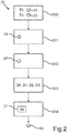
- Fig. 2 illustrates a method 20 for this, which can be carried out by the control device 12 for determining the shape and / or dimension 19 of the object 15.
- the background 15 ′ can be a driving surface.
- Fig. 3 shows an exemplary image 21 as it may have been generated with the camera 11.
- the control device 12 can define or set at least one scan line 23 in a first of the images, here the image 21 as an example.
- Each scan line 23 can correspond to the image of a ray 23 '(see Fig. 1 ), which extends straight away from the motor vehicle at a height He.
- the height He can be a known height of the object 15.
- the same scan lines 23 can be defined in the image 22 and in every other image. They thus represent scan lines corresponding to the scan lines 23 of the image 21.
- a profile 25 resulting along the scan line is formed for a predetermined image property 24, as is exemplified in FIG Fig. 4 is illustrated.
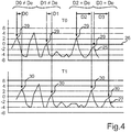
- Fig. 4 illustrates along an axis 26, which corresponds to the course of a scan line 23 of the image 21, the resulting profile 25 for an image property 24 which represents the value of an edge detection.
- the difference between the brightness values of neighboring pixels along the scan line 23 can be calculated for each point of the profile 25.
- Fig. 4 further illustrates how a corresponding profile 27 can be determined on the basis of the image property 24 for the image 22, that is to say for the measurement time T1, for the corresponding scan line in the image 22.
- At least one characteristic area 29 can now be determined for the profile 25 on the basis of a feature detection 28.
- the feature detection 28 can, for example, identify local maxima as a respective characteristic area.
- Each characteristic area 29 of the profile 25 can now be recognized again in the profile 27 as a recognized characteristic area 30. For example, this can be done on the basis of a correlation.
- a displacement width D0, D1, D2, D3 of the respective characteristic area 29 along the respective scan line 23 resulting between the measurement times T0 and T1 can now be determined for each characteristic area 29.
- the displacement distance D0, D1, D2, D3 depends on the one hand on the movement distance of the motor vehicle 10 during the approach 17 between the two measurement times T0, T1 and on the other hand on the distance between the image content displayed in the characteristic area 29 and the camera 11 The effect of parallax results from different distances between the image content, that is, depending on the distance between the respective image content and the camera 11, there is a different displacement distance D0, D1, D2, D3.
- a segmentation criterion 31 can be used as a basis for this, which provides, for example, a comparison of the respective displacement widths D0, D1, D2, D3 with an expected displacement width De, which results from the known height He of the object 15.
- the comparison can provide a tolerance interval within which an identity of the respective displacement width D0, D1, D2, D3 to the expected displacement width De is recognized or signaled.
- Fig. 3 illustrates how a segmentation 32 into two segments 33, 34 can be carried out along a scan line 23.
- the segment 33 can describe a section of a scan line 23 which is assigned to the object 15.
- the segment 34 can describe a section of a scan line 23 which is assigned to the background 15 '.
- a description of the dimensions and / or shape 19 of the object 15 can now be determined from all segments 33 of all scan lines 23.
- the dimension and / or shape 19 can be signaled to a further component in the motor vehicle, for example a driver assistance system, which brings the motor vehicle 10 autonomously or automatically to the object 15.
- a driver assistance system which brings the motor vehicle 10 autonomously or automatically to the object 15.
- the control device 12 carries out an analysis of the movement in the individual images 21, 22, taking into account the vehicle movement during the approach 17.
- Individual image areas of the images 21, 22 are assigned to the background 15 '(for example the driving surface or the ground level) on the one hand and to the object 15 of known height He on the other hand.
- the image areas are represented in the form of scan lines 23. In the three-dimensional space 23 ′, these correspond to the known height He of the object 15 and the shape of which is projected or imaged as scan lines 23 in the respective image 21, 22.
- These scan lines 23 are analyzed over temporally adjacent images 21, 22 with regard to their image property 24, for example by means of an edge detection function.
- each scan line 23 It is checked which parts or segments 33, 34 of each scan line 23 correspond to the expected object movement according to the expected displacement De (results in assignment to object 15) and which contradict the assumption (corresponds to assignment to background 15 '). With a sufficient number of scan lines 23 (for example more than 5, in particular more than 10), this enables segmentation 32 which can be used to determine the external shape of the object 15. A precise and unobstructed approach or approach 17 to the object 15 is thus possible.
- the height of this closest point can be deduced. This can be used as a further security feature.
- the motor vehicle 10 can thus be approached precisely to the target position described. If necessary, an offset can be used depending on the target position in order to position yourself relative to it.
- the approach presented offers a recognition of the outer shape of the object 15 and a recognition of an object geometry by analyzing an image property, for example an edge function, whereby a collision of the motor vehicle 10 with the object 15 can be prevented and an approach to a target position can be carried out.
- an image property for example an edge function
- the object 15 can be a trailer drawbar of a trailer 16, to whose trailer claw the motor vehicle 10 is to be coupled or docked.
- the trailer coupling 18 (trailer coupling device) can be positioned under the trailer claw, which defines the target position.
- the real target position can provide an offset, namely half the diameter of the coupling dome of the trailer claw to the described closest point of the object 15 to the motor vehicle 10.
Landscapes
- Engineering & Computer Science (AREA)
- Physics & Mathematics (AREA)
- General Physics & Mathematics (AREA)
- Theoretical Computer Science (AREA)
- Computer Vision & Pattern Recognition (AREA)
- Mechanical Engineering (AREA)
- Multimedia (AREA)
- Transportation (AREA)
- Data Mining & Analysis (AREA)
- Geometry (AREA)
- Artificial Intelligence (AREA)
- Bioinformatics & Cheminformatics (AREA)
- Bioinformatics & Computational Biology (AREA)
- Evolutionary Biology (AREA)
- Evolutionary Computation (AREA)
- General Engineering & Computer Science (AREA)
- Life Sciences & Earth Sciences (AREA)
- Length Measuring Devices By Optical Means (AREA)
- Image Analysis (AREA)
- Image Processing (AREA)
- Traffic Control Systems (AREA)
Claims (14)
- Procédé (20) de reconnaissance de forme d'un objet (15) dans une zone extérieure (14) d'un véhicule automobile (10), dans lequel, pendant que le véhicule automobile (10) se déplace par rapport à l'objet (15), respectivement une image (21, 22), qui montre l'objet (15) devant un arrière-plan (15') de la zone extérieure (14), est générée à au moins deux moments de mesure (T0, T1) différents par un dispositif de commande (12) du véhicule automobile (10) au moyen d'une caméra (11) et- au moins une ligne de balayage (23) est définie dans une première des images (21) et, pour chaque ligne de balayage (23), une ligne de balayage correspondante est définie dans chacune des autres images (22) et- pour chaque ligne de balayage (23) de la première image (21), un profil (25) obtenu le long de la ligne de balayage (23) est déterminé pour une propriété d'image (24) prédéfinie, ainsi qu'un profil (27) correspondant obtenu le long de la ligne de balayage respectivement correspondante de chaque autre image et- au moins une zone caractéristique (29) est déterminée dans le profil (25) de chaque ligne de balayage (23) de la première image (21) et- au moyen de la comparaison du profil (25) de chaque ligne de balayage (23) de la première image (21) avec le profil (27) respectivement correspondant de chaque autre image (22), l'au moins une zone caractéristique (29) est reconnue dans le profil (27) respectivement correspondant, dans lequel- pour chaque zone caractéristique (29), une longueur de décalage (D0, D1, D2, D3) de la zone caractéristique (29) obtenue entre les moments de mesure (T0, T1) le long de la ligne de balayage (23) respective est déterminée, ce qui permet de reconnaître dans quelle mesure la zone caractéristique (29) s'est décalée en raison du déplacement relatif du véhicule automobile (10) par rapport à l'objet (15) dans l'autre image (22) le long de la ligne de balayage (23) respective, ce décalage étant dépendant de la distance entre le contenu d'image respectif, qui est respectivement soit l'objet soit l'arrière-plan, et la caméra et, de manière correspondante- une distinction est faite entre l'objet (15) et l'arrière-plan (15') le long de chaque ligne de balayage (23) en fonction de la longueur de décalage (D0, D1, D2, D3) déterminée de chaque zone caractéristique (29) du profil (25) de la ligne de balayage (23), dans lequel- les lignes de balayage (23) et les lignes de balayage correspondantes présentent un tracé qui correspond à une image d'un rayon (23'), qui s'étend virtuellement en s'éloignant de manière rectiligne depuis le véhicule automobile (10) dans la zone extérieure (14) de manière tridimensionnelle à une hauteur (He) prédéfinie, dans lequel- la hauteur prédéfinie est ici une hauteur (He) attendue ou connue de l'objet (15), une longueur de décalage (De) attendue résultant de la hauteur (He) attendue ou connue de l'objet (15), dans lequel- une distinction est faite entre l'objet (15) et l'arrière-plan (15') au moyen d'une comparaison des longueurs de décalage (D0, D1, D2, D3) déterminées avec la longueur de décalage (De) attendue.
- Procédé (20) selon la revendication 1, dans lequel la propriété d'image prédéfinie comprend une valeur de couleur et/ou une valeur de contraste et/ou une valeur de détection de contours d'un contenu d'image de l'image.
- Procédé (20) selon l'une quelconque des revendications précédentes, dans lequel les zones caractéristiques (29) sont définies au moyen d'une détection d'attribut prédéfinie, qui identifie au moins un dessin caractéristique prédéfini dans le profil (25) respectif comme zone caractéristique.
- Procédé (20) selon l'une quelconque des revendications précédentes, dans lequel un déplacement en ligne droite du véhicule automobile (10) est reconnu et les images (21, 22) sont générées pendant le déplacement en ligne droite.
- Procédé (20) selon l'une quelconque des revendications précédentes, dans lequel une forme des lignes de balayage (23) est réglée en fonction d'un angle de braquage du véhicule automobile (10).
- Procédé (20) selon l'une quelconque des revendications précédentes, dans lequel une surface de roulement du véhicule automobile (10) est détectée comme arrière-plan (15').
- Procédé (20) selon l'une quelconque des revendications précédentes, dans lequel les images (21, 22) sont déterminées pendant un rapprochement du véhicule automobile (10) vers une barre d'attelage d'une remorque (16) et une dimension et/ou forme de la barre d'attelage est déterminée au moyen de la distinction entre l'objet (15) et l'arrière-plan (15').
- Procédé (20) selon l'une quelconque des revendications précédentes, dans lequel, pour faire la distinction entre l'objet (15) et l'arrière-plan (15'), une valeur de hauteur est associée à chaque zone caractéristique (29) du profil (25) de chaque ligne de balayage (23) en fonction de sa longueur de décalage et un profil de hauteur est ainsi généré le long de chaque ligne de balayage (23) et une distinction est faite entre l'objet (15) et l'arrière-plan (15') au moyen du profil de hauteur respectif le long de chaque ligne de balayage (23).
- Procédé (20) selon la revendication 8, dans lequel, dans les profils de hauteur, toutes les sections dont la valeur de hauteur est comprise dans un intervalle de valeurs prédéfini sont associées à l'objet (15).
- Procédé (20) selon la revendication 8 ou 9, dans lequel les valeurs de hauteur des zones caractéristiques (29) sont rastérisées sur un nombre prédéfini de valeurs de hauteur possibles.
- Procédé (20) selon l'une quelconque des revendications 8 à 10, dans lequel deux valeurs de hauteur possibles sont prévues, dont une représente une hauteur attendue (He) de l'objet (15) et une seconde une hauteur attendue de l'arrière-plan (15') et des profils de hauteur binaires sont ainsi générés.
- Procédé (20) selon l'une quelconque des revendications 8 à 11, dans lequel les profils de hauteur des lignes de balayage (23) sont réunis en une carte de hauteur bidimensionnelle.
- Dispositif de commande (12) pour un véhicule automobile (10), dans lequel le dispositif de commande (12) comporte un moyen de calcul, qui est configuré pour exécuter un procédé selon l'une quelconque des revendications précédentes.
- Véhicule automobile (10) doté d'au moins une caméra (11) destinée à détecter une zone extérieure (14) du véhicule automobile (10) et doté d'un dispositif de commande (12) selon la revendication 13, dans lequel le dispositif de commande (12) est couplé à l'au moins une caméra (11).
Applications Claiming Priority (1)
| Application Number | Priority Date | Filing Date | Title |
|---|---|---|---|
| DE102017219119.8A DE102017219119A1 (de) | 2017-10-25 | 2017-10-25 | Verfahren zur Formerkennung eines Objekts in einem Außenbereich eines Kraftfahrzeugs sowie Kraftfahrzeug |
Publications (2)
| Publication Number | Publication Date |
|---|---|
| EP3477249A1 EP3477249A1 (fr) | 2019-05-01 |
| EP3477249B1 true EP3477249B1 (fr) | 2021-12-01 |
Family
ID=63579163
Family Applications (1)
| Application Number | Title | Priority Date | Filing Date |
|---|---|---|---|
| EP18194225.1A Active EP3477249B1 (fr) | 2017-10-25 | 2018-09-13 | Procédé de reconnaissance de forme d'un objet dans une zone extérieure d'un véhicule automobile et véhicule automobile |
Country Status (4)
| Country | Link |
|---|---|
| US (1) | US10679073B2 (fr) |
| EP (1) | EP3477249B1 (fr) |
| CN (1) | CN109711423B (fr) |
| DE (1) | DE102017219119A1 (fr) |
Families Citing this family (5)
| Publication number | Priority date | Publication date | Assignee | Title |
|---|---|---|---|---|
| CN206291857U (zh) * | 2016-10-20 | 2017-06-30 | 成都佳诚弘毅科技股份有限公司 | 销轴距测量装置 |
| WO2019217586A1 (fr) * | 2018-05-08 | 2019-11-14 | Continental Automotive Systems, Inc. | Dispositif de suivi d'objet visuel |
| DE102020205468A1 (de) * | 2020-04-30 | 2021-11-04 | Zf Friedrichshafen Ag | Autonomes und/oder assistiertes Kuppeln eines Anhängers unter Berücksichtigung des Höhenprofils des Untergrunds |
| CN111928795B (zh) * | 2020-09-04 | 2021-10-01 | 浙江省计量科学研究院 | 一种牵引车、挂车外廓尺寸参数一并式测量方法 |
| US12428023B2 (en) * | 2023-01-12 | 2025-09-30 | Ford Global Technologies, Llc | System for a vehicle |
Family Cites Families (20)
| Publication number | Priority date | Publication date | Assignee | Title |
|---|---|---|---|---|
| US7777615B2 (en) | 2008-03-20 | 2010-08-17 | Toyota Motor Engineering & Manufacturing North America, Inc. | System for assisting the attachment of a trailer to a vehicle |
| DE102008046215A1 (de) | 2008-09-08 | 2009-09-17 | Daimler Ag | Verfahren zur Ankoppelung eines Fahrzeugs an eine Ladestation |
| DE102009053807A1 (de) | 2009-11-18 | 2011-05-19 | Conti Temic Microelectronic Gmbh | Verfahren zum Unterstützen eines Fahrers beim Einparken eines Fahrzeugs |
| DE102010063133A1 (de) | 2010-12-15 | 2012-06-21 | Robert Bosch Gmbh | Verfahren und System zur Bestimmung einer Eigenbewegung eines Fahrzeugs |
| US20130021446A1 (en) * | 2011-07-20 | 2013-01-24 | GM Global Technology Operations LLC | System and method for enhanced sense of depth video |
| DE102012003992A1 (de) | 2012-02-28 | 2013-08-29 | Wabco Gmbh | Zielführungssystem für Kraftfahrzeuge |
| JP5783319B2 (ja) * | 2012-03-02 | 2015-09-24 | 日産自動車株式会社 | 立体物検出装置及び立体物検出方法 |
| DE102012011121A1 (de) * | 2012-06-05 | 2013-12-05 | Connaught Electronics Ltd. | Verfahren zum Detektieren von Objekten nach der Methode des optischen Flusses, Kamerasystem und Kraftfahrzeug |
| GB2513393B (en) | 2013-04-26 | 2016-02-03 | Jaguar Land Rover Ltd | Vehicle hitch assistance system |
| US20150115571A1 (en) * | 2013-10-24 | 2015-04-30 | GM Global Technology Operations LLC | Smart tow |
| EP3640890B1 (fr) * | 2014-05-22 | 2023-06-21 | Mobileye Vision Technologies Ltd. | Systèmes et procédés de freinage d'un véhicule sur la base d'un objet détecté |
| DE102015201586A1 (de) * | 2015-01-29 | 2016-08-04 | Volkswagen Aktiengesellschaft | Verfahren und Vorrichtung zur Wiedererkennung eines Anhängers |
| US9499018B2 (en) | 2015-04-01 | 2016-11-22 | Robert Bosch Gmbh | Trailer coupling assistance system with vehicle video camera |
| US10275668B1 (en) * | 2015-09-21 | 2019-04-30 | Hrl Laboratories, Llc | System for collision detection and obstacle avoidance |
| US9933264B2 (en) * | 2015-04-06 | 2018-04-03 | Hrl Laboratories, Llc | System and method for achieving fast and reliable time-to-contact estimation using vision and range sensor data for autonomous navigation |
| US10150505B2 (en) | 2015-04-14 | 2018-12-11 | Continental Automotive Systems, Inc. | Automated hitching assist system |
| DE102015211754A1 (de) | 2015-06-24 | 2016-12-29 | Bayerische Motoren Werke Aktiengesellschaft | Parkassistenzsystem zum automatisierten Durchführen eines Einparkmanövers in eine Querparklücke mit Erkennung eines die Querparklücke nach hinten begrenzenden Bodenhindernisses |
| DE102015213404A1 (de) | 2015-07-16 | 2017-01-19 | Continental Teves Ag & Co. Ohg | Verfahren und Vorrichtung zum Ankuppeln eines Kraftfahrzeugs an einen Anhänger |
| DE102015015547A1 (de) * | 2015-12-03 | 2017-06-08 | Trw Automotive Safety Systems Gmbh | Fahrzeugsicherheitssystem, Baugruppe für ein Fahrzeugsicherheitssystem und Verfahren zum Herstellen eines Fahrzeugsicherheitssystems |
| DE102017219123B4 (de) * | 2017-10-25 | 2022-12-22 | Volkswagen Aktiengesellschaft | Verfahren zum Ermitteln von Objektgrenzen eines Objekts in einem Außenbereich eines Kraftfahrzeugs sowie Steuervorrichtung und Kraftfahrzeug |
-
2017
- 2017-10-25 DE DE102017219119.8A patent/DE102017219119A1/de not_active Withdrawn
-
2018
- 2018-09-13 EP EP18194225.1A patent/EP3477249B1/fr active Active
- 2018-10-19 US US16/164,954 patent/US10679073B2/en active Active
- 2018-10-25 CN CN201811252541.8A patent/CN109711423B/zh active Active
Also Published As
| Publication number | Publication date |
|---|---|
| DE102017219119A1 (de) | 2019-04-25 |
| US20190122053A1 (en) | 2019-04-25 |
| EP3477249A1 (fr) | 2019-05-01 |
| US10679073B2 (en) | 2020-06-09 |
| CN109711423B (zh) | 2023-06-30 |
| CN109711423A (zh) | 2019-05-03 |
Similar Documents
| Publication | Publication Date | Title |
|---|---|---|
| EP3477249B1 (fr) | Procédé de reconnaissance de forme d'un objet dans une zone extérieure d'un véhicule automobile et véhicule automobile | |
| EP3260357B1 (fr) | Véhicule comprenant un système de man uvre | |
| DE102016106298B4 (de) | Fusionsverfahren für eine Querverkehr-Applikation unter Verwenden von Radargeräten und einer Kamera | |
| DE102016106299B4 (de) | Raderfassung und ihre Applikation bei Objektverfolgung und Sensorregistrierung | |
| EP3084466B1 (fr) | Procédé de détection d'un marquage placé sur une route, dispositif d'assistance au conducteur et véhicule automobile | |
| EP3356203B1 (fr) | Procédé de détermination d'une zone de stationnement pour stationner un véhicule automobile, système d'assistance à la conduite et véhicule automobile | |
| EP2982572B1 (fr) | Procédé d'assistance d'un conducteur de véhicule automobile lors du stationnement, système d'assistance de conducteur et véhicule automobile | |
| EP2788245B1 (fr) | Procédé et dispositif pour localiser un emplacement de stationnement prédéfini | |
| EP3413086A1 (fr) | Procédé de caractérisation d'une remorque attachée à un véhicule tracteur, système d'aide à la conduite ainsi qu'ensemble attelé | |
| DE102016116859A1 (de) | Sensoranordnung für ein autonom betriebenes Nutzfahrzeug und ein Verfahren zur Rundumbilderfassung | |
| EP3284649B1 (fr) | Assistance au conducteur pour la mise en stationnement d'un véhicule automobile comprenant une remorque attelée à partir de capteurs virtuels | |
| DE102012022336A1 (de) | Verfahren zum Durchführen eines zumindest semi-autonomen Parkvorgangs eines Kraftfahrzeugs in eine Garage, Parkassistenzsystem und Kraftfahrzeug | |
| DE112017005447T5 (de) | Objekterfassungsvorrichtung | |
| DE102018122374B4 (de) | Verfahren zum Bestimmen eines ein Kraftfahrzeug umgebenden Freiraums, Computerprogrammprodukt, Freiraumbestimmungseinrichtung und Kraftfahrzeug | |
| DE102014204872B4 (de) | Verfahren und Anzeigesystem zum Anzeigen von Umgebungsinformationen eines Fahrzeugs | |
| DE102018217746A1 (de) | Verfahren zum Betrieb eines Fahrerassistenzsystems eines Kraftfahrzeugs und Kraftfahrzeug | |
| EP3710288B1 (fr) | Procédé et assistant de couplage de remorque pour le support d'un procédé de couplage d'un véhicule à moteur s'approchant en marche arrière d'une remorque | |
| DE102013202915A1 (de) | Verfahren und Vorrichtung zum Vermessen einer Parklücke für ein Einparkassistenzsystem eines Kraftfahrzeugs | |
| DE102016117712A1 (de) | Verfahren zum zumindest semi-autonomen Manövrieren eines Kraftfahrzeugs unter Berücksichtigung eines Erfassungsbereichs eines Sensors, Fahrerassistenzsystem sowie Kraftfahrzeug | |
| DE102016012345A1 (de) | Verfahren zum Erkennen von Objekten | |
| EP3327621B1 (fr) | Procédé d'aide à la conduite d'un véhicule automobile lors du stationnement, dispositif de calcul, système d'aide à la conduite ainsi que véhicule automobile | |
| DE102016114160A1 (de) | Verfahren zum zumindest semi-autonomen Manövrieren eines Kraftfahrzeugs in eine Garage auf Grundlage von Ultraschallsignalen und Kamerabildern, Fahrerassistenzsystem sowie Kraftfahrzeug | |
| EP3476696B1 (fr) | Procédé de détermination des limites d'un objet dans une zone externe d'un véhicule automobile ainsi que dispositif de commande et véhicule automobile | |
| EP4068223A1 (fr) | Procédé et système de détermination du niveau du sol à l'aide d'un réseau de neurones artificiels | |
| DE102017007958A1 (de) | Fahrerassistenzsystem für ein Fahrzeug und Fahrzeug mit einem solchen Fahrerassistenzsystem |
Legal Events
| Date | Code | Title | Description |
|---|---|---|---|
| PUAI | Public reference made under article 153(3) epc to a published international application that has entered the european phase |
Free format text: ORIGINAL CODE: 0009012 |
|
| STAA | Information on the status of an ep patent application or granted ep patent |
Free format text: STATUS: THE APPLICATION HAS BEEN PUBLISHED |
|
| AK | Designated contracting states |
Kind code of ref document: A1 Designated state(s): AL AT BE BG CH CY CZ DE DK EE ES FI FR GB GR HR HU IE IS IT LI LT LU LV MC MK MT NL NO PL PT RO RS SE SI SK SM TR |
|
| AX | Request for extension of the european patent |
Extension state: BA ME |
|
| STAA | Information on the status of an ep patent application or granted ep patent |
Free format text: STATUS: REQUEST FOR EXAMINATION WAS MADE |
|
| 17P | Request for examination filed |
Effective date: 20191104 |
|
| RBV | Designated contracting states (corrected) |
Designated state(s): AL AT BE BG CH CY CZ DE DK EE ES FI FR GB GR HR HU IE IS IT LI LT LU LV MC MK MT NL NO PL PT RO RS SE SI SK SM TR |
|
| GRAP | Despatch of communication of intention to grant a patent |
Free format text: ORIGINAL CODE: EPIDOSNIGR1 |
|
| STAA | Information on the status of an ep patent application or granted ep patent |
Free format text: STATUS: GRANT OF PATENT IS INTENDED |
|
| RIC1 | Information provided on ipc code assigned before grant |
Ipc: G01B 11/14 20060101AFI20210622BHEP Ipc: G01B 11/25 20060101ALI20210622BHEP Ipc: G06K 9/00 20060101ALI20210622BHEP Ipc: B62D 13/06 20060101ALI20210622BHEP Ipc: B60D 1/36 20060101ALI20210622BHEP Ipc: B60R 1/00 20060101ALI20210622BHEP Ipc: G06T 7/73 20170101ALI20210622BHEP Ipc: B60D 1/62 20060101ALI20210622BHEP |
|
| INTG | Intention to grant announced |
Effective date: 20210714 |
|
| GRAS | Grant fee paid |
Free format text: ORIGINAL CODE: EPIDOSNIGR3 |
|
| GRAA | (expected) grant |
Free format text: ORIGINAL CODE: 0009210 |
|
| STAA | Information on the status of an ep patent application or granted ep patent |
Free format text: STATUS: THE PATENT HAS BEEN GRANTED |
|
| AK | Designated contracting states |
Kind code of ref document: B1 Designated state(s): AL AT BE BG CH CY CZ DE DK EE ES FI FR GB GR HR HU IE IS IT LI LT LU LV MC MK MT NL NO PL PT RO RS SE SI SK SM TR |
|
| REG | Reference to a national code |
Ref country code: GB Ref legal event code: FG4D Free format text: NOT ENGLISH |
|
| REG | Reference to a national code |
Ref country code: AT Ref legal event code: REF Ref document number: 1452159 Country of ref document: AT Kind code of ref document: T Effective date: 20211215 Ref country code: CH Ref legal event code: EP |
|
| REG | Reference to a national code |
Ref country code: IE Ref legal event code: FG4D Free format text: LANGUAGE OF EP DOCUMENT: GERMAN |
|
| REG | Reference to a national code |
Ref country code: DE Ref legal event code: R096 Ref document number: 502018008018 Country of ref document: DE |
|
| REG | Reference to a national code |
Ref country code: LT Ref legal event code: MG9D |
|
| REG | Reference to a national code |
Ref country code: NL Ref legal event code: MP Effective date: 20211201 |
|
| PG25 | Lapsed in a contracting state [announced via postgrant information from national office to epo] |
Ref country code: RS Free format text: LAPSE BECAUSE OF FAILURE TO SUBMIT A TRANSLATION OF THE DESCRIPTION OR TO PAY THE FEE WITHIN THE PRESCRIBED TIME-LIMIT Effective date: 20211201 Ref country code: LT Free format text: LAPSE BECAUSE OF FAILURE TO SUBMIT A TRANSLATION OF THE DESCRIPTION OR TO PAY THE FEE WITHIN THE PRESCRIBED TIME-LIMIT Effective date: 20211201 Ref country code: FI Free format text: LAPSE BECAUSE OF FAILURE TO SUBMIT A TRANSLATION OF THE DESCRIPTION OR TO PAY THE FEE WITHIN THE PRESCRIBED TIME-LIMIT Effective date: 20211201 Ref country code: BG Free format text: LAPSE BECAUSE OF FAILURE TO SUBMIT A TRANSLATION OF THE DESCRIPTION OR TO PAY THE FEE WITHIN THE PRESCRIBED TIME-LIMIT Effective date: 20220301 |
|
| PG25 | Lapsed in a contracting state [announced via postgrant information from national office to epo] |
Ref country code: SE Free format text: LAPSE BECAUSE OF FAILURE TO SUBMIT A TRANSLATION OF THE DESCRIPTION OR TO PAY THE FEE WITHIN THE PRESCRIBED TIME-LIMIT Effective date: 20211201 Ref country code: PL Free format text: LAPSE BECAUSE OF FAILURE TO SUBMIT A TRANSLATION OF THE DESCRIPTION OR TO PAY THE FEE WITHIN THE PRESCRIBED TIME-LIMIT Effective date: 20211201 Ref country code: NO Free format text: LAPSE BECAUSE OF FAILURE TO SUBMIT A TRANSLATION OF THE DESCRIPTION OR TO PAY THE FEE WITHIN THE PRESCRIBED TIME-LIMIT Effective date: 20220301 Ref country code: LV Free format text: LAPSE BECAUSE OF FAILURE TO SUBMIT A TRANSLATION OF THE DESCRIPTION OR TO PAY THE FEE WITHIN THE PRESCRIBED TIME-LIMIT Effective date: 20211201 Ref country code: HR Free format text: LAPSE BECAUSE OF FAILURE TO SUBMIT A TRANSLATION OF THE DESCRIPTION OR TO PAY THE FEE WITHIN THE PRESCRIBED TIME-LIMIT Effective date: 20211201 Ref country code: GR Free format text: LAPSE BECAUSE OF FAILURE TO SUBMIT A TRANSLATION OF THE DESCRIPTION OR TO PAY THE FEE WITHIN THE PRESCRIBED TIME-LIMIT Effective date: 20220302 Ref country code: ES Free format text: LAPSE BECAUSE OF FAILURE TO SUBMIT A TRANSLATION OF THE DESCRIPTION OR TO PAY THE FEE WITHIN THE PRESCRIBED TIME-LIMIT Effective date: 20211201 |
|
| PG25 | Lapsed in a contracting state [announced via postgrant information from national office to epo] |
Ref country code: NL Free format text: LAPSE BECAUSE OF FAILURE TO SUBMIT A TRANSLATION OF THE DESCRIPTION OR TO PAY THE FEE WITHIN THE PRESCRIBED TIME-LIMIT Effective date: 20211201 |
|
| PG25 | Lapsed in a contracting state [announced via postgrant information from national office to epo] |
Ref country code: SM Free format text: LAPSE BECAUSE OF FAILURE TO SUBMIT A TRANSLATION OF THE DESCRIPTION OR TO PAY THE FEE WITHIN THE PRESCRIBED TIME-LIMIT Effective date: 20211201 Ref country code: SK Free format text: LAPSE BECAUSE OF FAILURE TO SUBMIT A TRANSLATION OF THE DESCRIPTION OR TO PAY THE FEE WITHIN THE PRESCRIBED TIME-LIMIT Effective date: 20211201 Ref country code: RO Free format text: LAPSE BECAUSE OF FAILURE TO SUBMIT A TRANSLATION OF THE DESCRIPTION OR TO PAY THE FEE WITHIN THE PRESCRIBED TIME-LIMIT Effective date: 20211201 Ref country code: PT Free format text: LAPSE BECAUSE OF FAILURE TO SUBMIT A TRANSLATION OF THE DESCRIPTION OR TO PAY THE FEE WITHIN THE PRESCRIBED TIME-LIMIT Effective date: 20220401 Ref country code: EE Free format text: LAPSE BECAUSE OF FAILURE TO SUBMIT A TRANSLATION OF THE DESCRIPTION OR TO PAY THE FEE WITHIN THE PRESCRIBED TIME-LIMIT Effective date: 20211201 Ref country code: CZ Free format text: LAPSE BECAUSE OF FAILURE TO SUBMIT A TRANSLATION OF THE DESCRIPTION OR TO PAY THE FEE WITHIN THE PRESCRIBED TIME-LIMIT Effective date: 20211201 |
|
| REG | Reference to a national code |
Ref country code: DE Ref legal event code: R097 Ref document number: 502018008018 Country of ref document: DE |
|
| PG25 | Lapsed in a contracting state [announced via postgrant information from national office to epo] |
Ref country code: IS Free format text: LAPSE BECAUSE OF FAILURE TO SUBMIT A TRANSLATION OF THE DESCRIPTION OR TO PAY THE FEE WITHIN THE PRESCRIBED TIME-LIMIT Effective date: 20220401 |
|
| PLBE | No opposition filed within time limit |
Free format text: ORIGINAL CODE: 0009261 |
|
| STAA | Information on the status of an ep patent application or granted ep patent |
Free format text: STATUS: NO OPPOSITION FILED WITHIN TIME LIMIT |
|
| PG25 | Lapsed in a contracting state [announced via postgrant information from national office to epo] |
Ref country code: DK Free format text: LAPSE BECAUSE OF FAILURE TO SUBMIT A TRANSLATION OF THE DESCRIPTION OR TO PAY THE FEE WITHIN THE PRESCRIBED TIME-LIMIT Effective date: 20211201 Ref country code: AL Free format text: LAPSE BECAUSE OF FAILURE TO SUBMIT A TRANSLATION OF THE DESCRIPTION OR TO PAY THE FEE WITHIN THE PRESCRIBED TIME-LIMIT Effective date: 20211201 |
|
| 26N | No opposition filed |
Effective date: 20220902 |
|
| PG25 | Lapsed in a contracting state [announced via postgrant information from national office to epo] |
Ref country code: SI Free format text: LAPSE BECAUSE OF FAILURE TO SUBMIT A TRANSLATION OF THE DESCRIPTION OR TO PAY THE FEE WITHIN THE PRESCRIBED TIME-LIMIT Effective date: 20211201 |
|
| PG25 | Lapsed in a contracting state [announced via postgrant information from national office to epo] |
Ref country code: MC Free format text: LAPSE BECAUSE OF FAILURE TO SUBMIT A TRANSLATION OF THE DESCRIPTION OR TO PAY THE FEE WITHIN THE PRESCRIBED TIME-LIMIT Effective date: 20211201 |
|
| REG | Reference to a national code |
Ref country code: CH Ref legal event code: PL |
|
| REG | Reference to a national code |
Ref country code: BE Ref legal event code: MM Effective date: 20220930 |
|
| PG25 | Lapsed in a contracting state [announced via postgrant information from national office to epo] |
Ref country code: IT Free format text: LAPSE BECAUSE OF FAILURE TO SUBMIT A TRANSLATION OF THE DESCRIPTION OR TO PAY THE FEE WITHIN THE PRESCRIBED TIME-LIMIT Effective date: 20211201 |
|
| P01 | Opt-out of the competence of the unified patent court (upc) registered |
Effective date: 20230523 |
|
| PG25 | Lapsed in a contracting state [announced via postgrant information from national office to epo] |
Ref country code: LU Free format text: LAPSE BECAUSE OF NON-PAYMENT OF DUE FEES Effective date: 20220913 |
|
| PG25 | Lapsed in a contracting state [announced via postgrant information from national office to epo] |
Ref country code: LI Free format text: LAPSE BECAUSE OF NON-PAYMENT OF DUE FEES Effective date: 20220930 Ref country code: IE Free format text: LAPSE BECAUSE OF NON-PAYMENT OF DUE FEES Effective date: 20220913 Ref country code: CH Free format text: LAPSE BECAUSE OF NON-PAYMENT OF DUE FEES Effective date: 20220930 |
|
| PG25 | Lapsed in a contracting state [announced via postgrant information from national office to epo] |
Ref country code: BE Free format text: LAPSE BECAUSE OF NON-PAYMENT OF DUE FEES Effective date: 20220930 |
|
| PG25 | Lapsed in a contracting state [announced via postgrant information from national office to epo] |
Ref country code: HU Free format text: LAPSE BECAUSE OF FAILURE TO SUBMIT A TRANSLATION OF THE DESCRIPTION OR TO PAY THE FEE WITHIN THE PRESCRIBED TIME-LIMIT; INVALID AB INITIO Effective date: 20180913 |
|
| PG25 | Lapsed in a contracting state [announced via postgrant information from national office to epo] |
Ref country code: CY Free format text: LAPSE BECAUSE OF FAILURE TO SUBMIT A TRANSLATION OF THE DESCRIPTION OR TO PAY THE FEE WITHIN THE PRESCRIBED TIME-LIMIT Effective date: 20211201 |
|
| PG25 | Lapsed in a contracting state [announced via postgrant information from national office to epo] |
Ref country code: MK Free format text: LAPSE BECAUSE OF FAILURE TO SUBMIT A TRANSLATION OF THE DESCRIPTION OR TO PAY THE FEE WITHIN THE PRESCRIBED TIME-LIMIT Effective date: 20211201 |
|
| PG25 | Lapsed in a contracting state [announced via postgrant information from national office to epo] |
Ref country code: TR Free format text: LAPSE BECAUSE OF FAILURE TO SUBMIT A TRANSLATION OF THE DESCRIPTION OR TO PAY THE FEE WITHIN THE PRESCRIBED TIME-LIMIT Effective date: 20211201 |
|
| PG25 | Lapsed in a contracting state [announced via postgrant information from national office to epo] |
Ref country code: MT Free format text: LAPSE BECAUSE OF FAILURE TO SUBMIT A TRANSLATION OF THE DESCRIPTION OR TO PAY THE FEE WITHIN THE PRESCRIBED TIME-LIMIT Effective date: 20211201 |
|
| PGFP | Annual fee paid to national office [announced via postgrant information from national office to epo] |
Ref country code: DE Payment date: 20240930 Year of fee payment: 7 |
|
| PGFP | Annual fee paid to national office [announced via postgrant information from national office to epo] |
Ref country code: GB Payment date: 20240924 Year of fee payment: 7 |
|
| PGFP | Annual fee paid to national office [announced via postgrant information from national office to epo] |
Ref country code: FR Payment date: 20240925 Year of fee payment: 7 |
|
| REG | Reference to a national code |
Ref country code: AT Ref legal event code: MM01 Ref document number: 1452159 Country of ref document: AT Kind code of ref document: T Effective date: 20230913 |
|
| PG25 | Lapsed in a contracting state [announced via postgrant information from national office to epo] |
Ref country code: AT Free format text: LAPSE BECAUSE OF NON-PAYMENT OF DUE FEES Effective date: 20230913 |
|
| PG25 | Lapsed in a contracting state [announced via postgrant information from national office to epo] |
Ref country code: AT Free format text: LAPSE BECAUSE OF NON-PAYMENT OF DUE FEES Effective date: 20230913 |
|
| PGFP | Annual fee paid to national office [announced via postgrant information from national office to epo] |
Ref country code: AT Payment date: 20260410 Year of fee payment: 5 |