EP3477360B1 - Vorrichtung zur anzeige stereoskopischer bilder und verfahren zur anzeige stereoskopischer bilder - Google Patents
Vorrichtung zur anzeige stereoskopischer bilder und verfahren zur anzeige stereoskopischer bilder Download PDFInfo
- Publication number
- EP3477360B1 EP3477360B1 EP17819915.4A EP17819915A EP3477360B1 EP 3477360 B1 EP3477360 B1 EP 3477360B1 EP 17819915 A EP17819915 A EP 17819915A EP 3477360 B1 EP3477360 B1 EP 3477360B1
- Authority
- EP
- European Patent Office
- Prior art keywords
- shutters
- mechanical
- rays
- display
- small images
- Prior art date
- Legal status (The legal status is an assumption and is not a legal conclusion. Google has not performed a legal analysis and makes no representation as to the accuracy of the status listed.)
- Active
Links
Images

Classifications
-
- G—PHYSICS
- G02—OPTICS
- G02B—OPTICAL ELEMENTS, SYSTEMS OR APPARATUS
- G02B30/00—Optical systems or apparatus for producing three-dimensional [3D] effects, e.g. stereoscopic images
- G02B30/20—Optical systems or apparatus for producing three-dimensional [3D] effects, e.g. stereoscopic images by providing first and second parallax images to an observer's left and right eyes
- G02B30/26—Optical systems or apparatus for producing three-dimensional [3D] effects, e.g. stereoscopic images by providing first and second parallax images to an observer's left and right eyes of the autostereoscopic type
- G02B30/30—Optical systems or apparatus for producing three-dimensional [3D] effects, e.g. stereoscopic images by providing first and second parallax images to an observer's left and right eyes of the autostereoscopic type involving parallax barriers
-
- G—PHYSICS
- G02—OPTICS
- G02B—OPTICAL ELEMENTS, SYSTEMS OR APPARATUS
- G02B30/00—Optical systems or apparatus for producing three-dimensional [3D] effects, e.g. stereoscopic images
- G02B30/20—Optical systems or apparatus for producing three-dimensional [3D] effects, e.g. stereoscopic images by providing first and second parallax images to an observer's left and right eyes
- G02B30/22—Optical systems or apparatus for producing three-dimensional [3D] effects, e.g. stereoscopic images by providing first and second parallax images to an observer's left and right eyes of the stereoscopic type
- G02B30/24—Optical systems or apparatus for producing three-dimensional [3D] effects, e.g. stereoscopic images by providing first and second parallax images to an observer's left and right eyes of the stereoscopic type involving temporal multiplexing, e.g. using sequentially activated left and right shutters
-
- G—PHYSICS
- G02—OPTICS
- G02B—OPTICAL ELEMENTS, SYSTEMS OR APPARATUS
- G02B30/00—Optical systems or apparatus for producing three-dimensional [3D] effects, e.g. stereoscopic images
- G02B30/20—Optical systems or apparatus for producing three-dimensional [3D] effects, e.g. stereoscopic images by providing first and second parallax images to an observer's left and right eyes
- G02B30/26—Optical systems or apparatus for producing three-dimensional [3D] effects, e.g. stereoscopic images by providing first and second parallax images to an observer's left and right eyes of the autostereoscopic type
- G02B30/27—Optical systems or apparatus for producing three-dimensional [3D] effects, e.g. stereoscopic images by providing first and second parallax images to an observer's left and right eyes of the autostereoscopic type involving lenticular arrays
-
- G—PHYSICS
- G02—OPTICS
- G02B—OPTICAL ELEMENTS, SYSTEMS OR APPARATUS
- G02B30/00—Optical systems or apparatus for producing three-dimensional [3D] effects, e.g. stereoscopic images
- G02B30/20—Optical systems or apparatus for producing three-dimensional [3D] effects, e.g. stereoscopic images by providing first and second parallax images to an observer's left and right eyes
- G02B30/26—Optical systems or apparatus for producing three-dimensional [3D] effects, e.g. stereoscopic images by providing first and second parallax images to an observer's left and right eyes of the autostereoscopic type
- G02B30/30—Optical systems or apparatus for producing three-dimensional [3D] effects, e.g. stereoscopic images by providing first and second parallax images to an observer's left and right eyes of the autostereoscopic type involving parallax barriers
- G02B30/31—Optical systems or apparatus for producing three-dimensional [3D] effects, e.g. stereoscopic images by providing first and second parallax images to an observer's left and right eyes of the autostereoscopic type involving parallax barriers involving active parallax barriers
-
- G—PHYSICS
- G03—PHOTOGRAPHY; CINEMATOGRAPHY; ANALOGOUS TECHNIQUES USING WAVES OTHER THAN OPTICAL WAVES; ELECTROGRAPHY; HOLOGRAPHY
- G03B—APPARATUS OR ARRANGEMENTS FOR TAKING PHOTOGRAPHS OR FOR PROJECTING OR VIEWING THEM; APPARATUS OR ARRANGEMENTS EMPLOYING ANALOGOUS TECHNIQUES USING WAVES OTHER THAN OPTICAL WAVES; ACCESSORIES THEREFOR
- G03B35/00—Stereoscopic photography
- G03B35/18—Stereoscopic photography by simultaneous viewing
-
- G—PHYSICS
- G03—PHOTOGRAPHY; CINEMATOGRAPHY; ANALOGOUS TECHNIQUES USING WAVES OTHER THAN OPTICAL WAVES; ELECTROGRAPHY; HOLOGRAPHY
- G03B—APPARATUS OR ARRANGEMENTS FOR TAKING PHOTOGRAPHS OR FOR PROJECTING OR VIEWING THEM; APPARATUS OR ARRANGEMENTS EMPLOYING ANALOGOUS TECHNIQUES USING WAVES OTHER THAN OPTICAL WAVES; ACCESSORIES THEREFOR
- G03B35/00—Stereoscopic photography
- G03B35/18—Stereoscopic photography by simultaneous viewing
- G03B35/24—Stereoscopic photography by simultaneous viewing using apertured or refractive resolving means on screens or between screen and eye
-
- H—ELECTRICITY
- H04—ELECTRIC COMMUNICATION TECHNIQUE
- H04N—PICTORIAL COMMUNICATION, e.g. TELEVISION
- H04N13/00—Stereoscopic video systems; Multi-view video systems; Details thereof
- H04N13/30—Image reproducers
- H04N13/302—Image reproducers for viewing without the aid of special glasses, i.e. using autostereoscopic displays
- H04N13/31—Image reproducers for viewing without the aid of special glasses, i.e. using autostereoscopic displays using parallax barriers
- H04N13/315—Image reproducers for viewing without the aid of special glasses, i.e. using autostereoscopic displays using parallax barriers the parallax barriers being time-variant
-
- H—ELECTRICITY
- H04—ELECTRIC COMMUNICATION TECHNIQUE
- H04N—PICTORIAL COMMUNICATION, e.g. TELEVISION
- H04N13/00—Stereoscopic video systems; Multi-view video systems; Details thereof
- H04N13/30—Image reproducers
- H04N13/349—Multi-view displays for displaying three or more geometrical viewpoints without viewer tracking
- H04N13/354—Multi-view displays for displaying three or more geometrical viewpoints without viewer tracking for displaying sequentially
Definitions
- the present invention is related to a stereoscopic image display device and a stereoscopic image display method that enable a stereoscopic image (a three-dimensional image) to be viewed with a similar feeling to everyday life without the use of special glasses.
- Stereoscopic image display methods are roughly classified into a method employing a two-viewpoint system that realizes stereoscopic vision by reproducing binocular parallax and convergence, a method employing a multi-viewpoint system that presents, by using lenticular lenses or the like, to left and right eyes multi-view images that are laterally arrayed, and a method employing a spatial image reproducing system that forms a stereoscopic image in space by using data (images) that have recorded optical spatial images of an object (e.g. refer to Non Patent Literature 1).
- the method employing the spatial image reproducing system is regarded as an ideal stereoscopic image display method that satisfies all factors with which humans perceive stereoscopic effect based on their visual functions (e.g. refer to Non Patent Literature 2).
- Patent Literature 1 a stereoscopic image display method in which a display control panel having a large number of minute light-transmission portions is provided, behind the display control panel, a group of image display panels, which includes a plurality of image display panels displaying a large number of small images of an object viewed from positions of the respective minute light-transmission portions, is disposed, the minute light-transmission portions are made to rapidly sequentially selectively allow light to pass through, and at the same time, the small images are displayed at positions on the image display panels corresponding to the minute light-transmission portions that have become to allow light to pass through, is suggested.
- a three-dimensional stereoscopic image display device including: a plurality of image reproduction panels respectively displaying a plurality of group images, in each of which, a large number of small images to become a base of a stereoscopic image are displayed side by side at a same time in a state of not overlapping, and an object is viewed from positions substantially slightly different from each other; an image display panel sequentially displaying in a time-division manner the group images respectively displayed on the plurality of image reproduction panels; and a display control panel disposed in front of the image display panel, having a plurality of group minute light-transmission portions each opening and closing in synchronization with each of the small images of the group images displayed on the image display panel in a time-division manner, wherein the group minute light-transmission portions each have a large number of minute light-transmission portions each of which is in a pinhole-like state or a slit-like state, is suggested.
- a three-dimensional video display including: a video display panel for displaying a video, a dot-shaped light transmitter forming panel having light transmitters on which video light from the video display panel is incident arranged therein in the shape of a plane with predetermined spacing, and shutter means for changing the position of the light transmitter in the plane, is suggested.
- the plurality of image reproduction panels each displaying the group images are disposed on the back side of the image display panel.
- the present invention has been made in consideration of the above circumstances, and has as its object to provide a stereoscopic image display device and a stereoscopic image display method that enable a stereoscopic image (three-dimensional image) having high image quality and containing a large amount of information to be viewed with a similar feeling to everyday life without the use of special glasses.
- a stereoscopic image display device according to a first aspect of the present invention is described in claim 1 and a stereoscopic image display method according to a second aspect of the present invention is described in claim 10.
- the number of the display for displaying the small images is only one, thus it is possible to make the stereoscopic image display device compact. Also, it is possible by means of the first mechanical shutters to extract at a high speed by time-dividing the rays output from the small images as the partial rays each output from the plurality of partial regions. This makes it possible to reduce the spatial and temporal limitations when using the stereoscopic image display device and when applying the stereoscopic image display method.
- the rays output from the small images are extracted in a time-division manner as the partial rays output from the partial regions of the small images by using the first mechanical shutters, it is possible to prevent the partial rays, which are each output from the partial regions of the small images next to each other displayed on the display, from overlapping each other in space, and it is possible to extract the partial rays not including noise content.
- the rays reconstructed from the partial rays also do not include noise content, and thus, this makes it possible to form a stereoscopic image without distortions.
- the partial rays are extracted by using the first mechanical shutters, it is possible to prevent color tone changes of the partial rays and to suppress attenuation of light quantity of the partial rays, and also, since the rays are reconstructed from the partial rays by using the second mechanical shutters, it is possible to prevent color tone changes of the rays and to suppress attenuation of light quantity of the rays; therefore, a bright stereoscopic image with accurate color tone can be obtained.
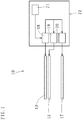
- a stereoscopic image display device (10) includes a display (12) displaying side by side a plurality of small images (11), each of which containing three-dimensional display data, to convert the three-dimensional display data into rays and output the rays from each of the small images (11).
- a display (12) displaying side by side a plurality of small images (11), each of which containing three-dimensional display data, to convert the three-dimensional display data into rays and output the rays from each of the small images (11).
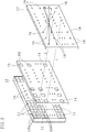
- a plurality of partial regions (13) are provided, and in front of the display (12) a first mechanical shutter panel (15) having first mechanical shutters (14) disposed so as to correspond to positions of the small images (11) displayed on the display (12) is provided.
- the first mechanical shutters (14) extract in a time-division manner the rays output from each of the small images (11) as partial rays each output from the plurality of partial regions (13) and transmit the partial rays forward. Also, in front of the first mechanical shutters (14) a second mechanical shutter panel (17) having second mechanical shutters (16) disposed so as to correspond to the positions of the small images (11) displayed on the display (12) is provided. The second mechanical shutters (16) transmit forward the partial rays extracted in a time-division manner per each of the small images (11), reconstruct the partial rays as the rays, and converge each of the reconstructed rays in front to form a stereoscopic image (three-dimensional image).
- the stereoscopic image display device (10) includes a control unit (22) provided with: an image displaying means (18) for displaying on the display (12) the small images (11) containing the three-dimensional display data; a first mechanical shutter operating means (19) for positioning the first mechanical shutters (14) such that the first mechanical shutters (14) correspond to the positions of the small images (11) displayed on the display (12) and performing on/off operations (open/close operations) of the first mechanical shutters (14); a second mechanical shutter operating means (20) for positioning the second mechanical shutters (16) such that a light axis L exists at a central portion of each of the small images (11) displayed on the display (12) and performing on/off operations of the second mechanical shutters (16) such that off-time (off-time: when a shutter is closed) of the second mechanical shutters (16) synchronizes with off-time of the first mechanical shutters (14); and a small image making means (21) for making the small images (11) containing the three-dimensional display data.
- a control unit (22) provided with: an image
- the number of pixels of the display (12) is preferably equal to or more than 4,000 pixels in a transverse (horizontal) direction, and equal to or more than 2,000 pixels in a longitudinal (perpendicular) direction (i.e. it is preferable to be a display having the number of pixels of 4K or more, more preferably 8K or more). This makes it possible to display many high-definition small images (small images each containing big three-dimensional display data) side by side on the one display (12) and to form a high-resolution three-dimensional image.
- the first mechanical shutters (14) are composed of a plurality of MEMS shutters (micro mechanical shutters based on Micro Electro-Mechanical System technology). This allows, for example, the MEMS shutters each having a same size as each of the pixels of the display (12) to be arranged in the first mechanical shutter panel (15) in accord with disposition of the pixels of the display (12) (to be disposed with a same density as a pixel density of the display (12)).
- MEMS shutters micro mechanical shutters based on Micro Electro-Mechanical System technology
- the selected MEMS shutters serve as the first mechanical shutters (14) having same shapes as the partial regions (13).
- the second mechanical shutters (16) are composed of a plurality of the MEMS shutters. This allows, for example, the MEMS shutters each having the same size as each of the pixels of the display (12) to be arranged in the second mechanical shutter panel (17) in accord with the disposition of the pixels of the display (12). Therefore, by selecting some of the MEMS shutters located within a range corresponding to a central portion of each of the small images (11) displayed on the display (12) from the plurality of MEMS shutters disposed in the second mechanical shutter panel (17), it is possible to make the selected MEMS shutters serve as the second mechanical shutters (16) positioned such that the light axis L passes through the central portion of each of the small images (11).
- the first mechanical shutters (14) As optical shutters, it is possible to extract the partial rays in which the color tone changes are prevented and the attenuation of light quantity is suppressed from the rays output from each of the small images.
- the second mechanical shutters (16) as the optical shutters, it is possible to transmit the partial rays toward the front of the second mechanical shutter panel (17) while preventing the color tone changes and suppressing the attenuation of light quantity. This makes it possible to reconstruct the rays in which there is no color tone change and the attenuation of light quantity is suppressed comparing to the rays output from each of the small images (11) by using the partial rays extracted from each of the small images (11), and converge each of the rays.
- the first mechanical shutter panel (15) be disposed so as to abut on the display (12) or closely disposed so as to have a space of equal to or less than 500 ⁇ m with respect to the display (12).
- a distance between the display (12) and the second mechanical shutter panel (17) is decided based on the ray route information in the three-dimensional display data contained in each of the small images (11) (such that the partial rays output from the partial regions (13) of each of the small images (11) can pass in a same manner through the second mechanical shutters (16) toward the front of the second mechanical shutter panel (17)).
- one of the first mechanical shutters (14) corresponding to a position of one of the partial regions (13) selected from the plurality of partial regions (13) provided in each of the small images (11) becomes on-time. That is, each time the second mechanical shutters (16) are switched on or off, a different one of the partial regions (13) is sequentially selected from the plurality of partial regions (13) provided in each of the small images (11), and one of the first mechanical shutters (14) corresponding to the selected partial region (13) becomes on-time while synchronizing with on-time of the second mechanical shutters (16).
- the first mechanical shutters (14a) corresponding to positions of a plurality (four, in Fig. 3 ) of the partial regions (13a) that are located at positions away from each other (for example, at least not adjacent positions) may become on-time. That is, it may be that in the same way as above, each time the second mechanical shutters (16) are switched on or off, a plurality of the first mechanical shutters (14a) located at different positions away from each other are sequentially selected, and the selected first mechanical shutters (14a) become on-time while synchronizing with on-time of the second mechanical shutters (16).
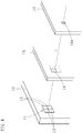
- each of the second mechanical shutters (16) may be a pinhole-like state, or, as shown in Fig. 4 , each of the second mechanical shutters (16a) may be a slit-like state (the light axis L passes through the central portion of each of the small images (11)).
- each of the second mechanical shutters (16) is a pinhole-like state
- the partial rays entered from an inlet side (the first mechanical shutter panel (15) side) of each of the second mechanical shutters (16) spread out in a light cone shape when going out from an outlet side of each of the second mechanical shutters (16) (toward the front of the second mechanical shutter panel (17)).
- the rays reconstructed from the partial rays also spread out in a light cone shape, and thus, a stereoscopic image having parallax information in overall directions such as horizontal, vertical, and oblique directions is formed.
- each of the second mechanical shutters (16a) is in a slit-like state
- the partial rays entered from an inlet side of each of the second mechanical shutters (16a) spread out when going out from an outlet side of each of the second mechanical shutters (16a), on each of planes parallel to a width direction of the slit, in a fan shape having a base portion at the outlet side of each of the second mechanical shutters (16a).
- the rays reconstructed from the partial rays also spread out in the fan shapes along the longitudinal direction of each of the second mechanical shutters (16a), and thus, a stereoscopic image having parallax information only in the width direction of the second mechanical shutters (16a) is formed. Therefore, to observe the stereoscopic image, an observer must be located such that their eyes are side-by-side along the width direction of the second mechanical shutters (16a), and thus, a limitation occurs for observing the stereoscopic image.
- the image displaying means (18) of the control unit (22) is configured by loading into a computer a program, which includes a small image displaying function for reading the plurality of three-dimensional display data, converting each of the data into a signal for displaying the small images, and inputting the signals to the display (12).
- a dedicated circuit for converting the three-dimensional display data into the signals for displaying the small images may be connected to a signal input side of the display (12). By using the dedicated circuit, it is possible to increase the speed of displaying the small images.
- the first mechanical shutter operating means (19) of the control unit (22) is configured by loading into a computer a program, which includes a MEMS shutter operating function for obtaining, from the image displaying means (18), positional information of pixels used for displaying each of the small images (11) displayed on the display (12) and inputting driving signals that, with respect to each of the MEMS shutters in the first mechanical shutter panel (15), turn on in a time-division manner as the first mechanical shutters (14) the plurality of MEMS shutters located within ranges each corresponding to the displaying ranges of the plurality of partial regions (13) provided in each of the small images (11) and at the same time, turn off all the rest of the MEMS shutters.
- a MEMS shutter operating function for obtaining, from the image displaying means (18), positional information of pixels used for displaying each of the small images (11) displayed on the display (12) and inputting driving signals that, with respect to each of the MEMS shutters in the first mechanical shutter panel (15), turn on in a time-division manner as the first mechanical shutter
- the second mechanical shutter operating means (20) of the control unit (22) is configured by loading into a computer a program, which includes a MEMS shutter operating function for obtaining, from the image displaying means (18), the positional information of the pixels used for displaying each of the small images (11) displayed on the display (12), and with respect to each of the MEMS shutters in the second mechanical shutter panel (17), turning on or off the plurality of MEMS shutters located within a range corresponding to the central portion of each of the small images (11) in synchronization with on-time and off-time of the plurality of MEMS shutters composing the first mechanical shutters (14).
- a MEMS shutter operating function for obtaining, from the image displaying means (18), the positional information of the pixels used for displaying each of the small images (11) displayed on the display (12), and with respect to each of the MEMS shutters in the second mechanical shutter panel (17), turning on or off the plurality of MEMS shutters located within a range corresponding to the central portion of each of the small images (11) in synchronization with on-
- the small image making means (21) of the control unit (22) is configured by loading into a computer, for example, a computer graphics function for making images of a three-dimensional object as three-dimensional display data by moving a virtual camera in a three-dimensional space.
- the small image making means (21) by loading into a computer a function for obtaining image data by imaging through an imaging means (e.g. a stereo camera) the object to become a base of a stereoscopic image supposed to be displayed, extracting, from the image data, polygons composing a surface of the object viewed from viewpoints of the stereo camera, and obtaining, as the three-dimensional display data, vertex coordinates of the extracted polygons, connection information about the vertexes of the polygons next to each other, and color information of each of the polygons.
- an imaging means e.g. a stereo camera
- a stereoscopic image display method using a stereoscopic image display device (10) according to an embodiment of the present invention will be described next.
- the stereoscopic image display method comprises a step of displaying side by side on a display (12) a plurality of small images (11), each of which containing three-dimensional display data, to convert the three-dimensional display data into rays and output the rays from each of the small images (11); a step of extracting the rays in a time-division manner as partial rays each output from a plurality of partial regions (13) provided in the small images (11) and transmitting the partial rays toward the front of a first mechanical shutter panel (15) by using first mechanical shutters (14) disposed in front of the display (12) so as to correspond to positions of the small images (11) displayed on the display (12); and a step of transmitting the partial rays extracted in a time-division manner per each of the small images (11) toward the front of a second mechanical shutter panel (17), reconstructing the partial rays as the rays, and converging each of the reconstructed rays, by using second mechanical shutters (16
- the rays output from each of the small images (11) are extracted as the partial rays output from the partial regions (13) of each of the small images (11) by using the first mechanical shutters (14), it is possible to prevent color tone changes of the partial rays, and besides, to suppress attenuation of light quantity of the partial rays. Further, even if the small images (11) next to each other are displayed on the display (12) being closely adjacent, the partial rays output from each of the partial regions (13) of the small images (11) next to each other each have different ray routes, and thus, the partial rays never cross (overlap) each other in space. Therefore, the extracted partial rays do not include noise content.
- the number of time-divisions i.e. the number of the partial regions are decided in consideration of the speed of opening and closing the first mechanical shutters (14) such that the partial rays from all the partial regions can be extracted within the afterimage retention time of the eye. Also, off-time of the second mechanical shutters (16) is synchronized with off-time of the first mechanical shutters (14) .
- Each of the rays then diffuses forward after being converged at the position S, and thus, if observing each of the rays that diffuses from the front, virtual object points emitting each of the diffusing rays can be seen at the position S where each of the rays are converged.
- a stereoscopic image As an aggregation of the virtual object points.
- the rays diffusing from the aggregation of the virtual object points have a same quality as the rays output from each of the small images (11), the three-dimensional image to be observed becomes a high-definition image which is bright and with no distortion.
- the display and the first mechanical shutter panel are disposed so as to abut on each other
- it may be a structure where the display and the first mechanical shutter panel are integrated, that is, where the MEMS shutters are respectively provided on the pixels of the display and the MEMS shutters are made to serve as the first mechanical shutters.
- the stereoscopic image display device and the stereoscopic image display method are configured by using the first and second mechanical shutters (for example, the MEMS shutters), it is conceivable to use liquid crystal shutters as the first and second mechanical shutters (in this case, interpret "mechanical shutters” as “liquid crystal shutters”).
- the mechanical shutters have a quicker responsiveness comparing to the liquid crystal shutters and can obtain a more vivid and precise stereoscopic image.
- the present invention has applicability as a stereoscopic image display device for video game consoles and medical use, and also as a stereoscopic image display method used at video game arcades, amusement parks, movie theaters, and medical institutions.
Landscapes
- Physics & Mathematics (AREA)
- General Physics & Mathematics (AREA)
- Optics & Photonics (AREA)
- Engineering & Computer Science (AREA)
- Multimedia (AREA)
- Signal Processing (AREA)
- Testing, Inspecting, Measuring Of Stereoscopic Televisions And Televisions (AREA)
- Stereoscopic And Panoramic Photography (AREA)
- Mechanical Light Control Or Optical Switches (AREA)
Claims (10)
- Vorrichtung zur Anzeige stereoskopischer Bilder (10), aufweisend:eine Anzeige (12), die mehrere kleine Bilder (11, 11a), von denen jedes dreidimensionale Anzeigedaten enthält, Seite an Seite anzeigt, um die dreidimensionalen Anzeigedaten in Strahlen zu konvertieren und die Strahlen aus jedem der kleinen Bilder auszugeben;ein erstes mechanisches Verschlusspaneel (15), das angrenzend an die Anzeige angeordnet oder in die Anzeige integriert ist, wobei das erste mechanische Verschlusspaneel erste mechanische Verschlüsse (14, 14a) hat, die aus mehreren ersten MEMS-Verschlüssen gebildet sind, wobei jeder der ersten MEMS-Verschlüsse eine gleiche Größe wie jedes Pixel der Anzeige hat, wobei die ersten MEMS-Verschlüsse gemäß der Anordnung der Pixel der Anzeige platziert sind; undein zweites mechanisches Verschlusspaneel (17), das vor dem ersten mechanischen Verschlusspaneel angeordnet ist, wobei das zweite mechanische Verschlusspaneel zweite mechanische Verschlüsse (16, 16a) hat, die aus mehreren zweiten MEMS-Verschlüssen gebildet sind, wobei jeder der zweiten MEMS-Verschlüsse die gleiche Größe wie jedes Pixel der Anzeige hat, wobei die zweiten MEMS-Verschlüsse gemäß der Anordnung der Pixel der Anzeige platziert sind,wobei die ersten mechanischen Verschlüsse vor der Anzeige angeordnet sind, um jeweils Positionen mehrerer Teilbereiche (13, 13a), die in jedem der auf der Anzeige angezeigten kleinen Bilder bereitgestellt sind, zu entsprechen, wobei die ersten mechanischen Verschlüsse konfiguriert sind, um die Strahlen in einer Zeitverteilung-Weise als Teilstrahlen, die jeweils aus den mehreren Teilbereichen ausgegeben werden, zu extrahieren und die Teilstrahlen nach vorne abzustrahlen; undwobei die zweiten mechanischen Verschlüsse vor den ersten mechanischen Verschlüssen angeordnet sind, um jeweils den Positionen der auf der Anzeige angezeigten kleinen Bilder zu entsprechen, und konfiguriert sind, die in einer Zeitverteilung-Weise pro jedes der kleinen Bilder extrahierten Teilstrahlen nach vorne abzustrahlen, die Teilstrahlen als die Strahlen zu rekonstruieren und jeden der rekonstruierten Strahlen vorne zu konvergieren, um ein dreidimensionales Bild zu erzeugen.
- Vorrichtung zur Anzeige stereoskopischer Bilder nach Anspruch 1, wobei jeder der zweiten mechanischen Verschlüsse auf einer Lichtachse angeordnet ist, die sich durch einen zentralen Abschnitt eines entsprechenden der kleinen Bilder erstreckt.
- Vorrichtung zur Anzeige stereoskopischer Bilder nach einem der Ansprüche 1 bis 2, wobei eine Sperrzeit der zweiten mechanischen Verschlüsse mit einer Sperrzeit der ersten mechanischen Verschlüsse synchron ist.
- Vorrichtung zur Anzeige stereoskopischer Bilder nach Anspruch 3, wobei, wenn die zweiten mechanischen Verschlüsse in Durchlasszeit sind, einer der ersten mechanischen Verschlüsse, der einer Position eines der in jedem der kleinen Bilder bereitgestellten mehreren Teilbereiche entspricht, in Durchlasszeit ist.
- Vorrichtung zur Anzeige stereoskopischer Bilder nach Anspruch 3, wobei, wenn die zweiten mechanischen Verschlüsse in Durchlasszeit sind, die ersten mechanischen Verschlüsse, die Positionen derjenigen Teilbereiche der in jedem der kleinen Bilder bereitgestellten mehreren Teilbereiche entsprechen, die an voneinander entfernten Positionen angeordnet sind, in Durchlasszeit sind.
- Vorrichtung zur Anzeige stereoskopischer Bilder nach einem der Ansprüche 1 bis 5, wobei jeder der zweiten mechanischen Verschlüsse in einem lochblendeartigen Zustand ist.
- Vorrichtung zur Anzeige stereoskopischer Bilder nach einem der Ansprüche 1 bis 5, wobei jeder der zweiten mechanischen Verschlüsse in einem schlitzartigen Zustand ist.
- Vorrichtung zur Anzeige stereoskopischer Bilder nach einem der Ansprüche 1 bis 7, wobei die dreidimensionalen Anzeigedaten aus Bilddaten, die durch Abbildungseinrichtungen gewonnen werden, erzeugt werden.
- Vorrichtung zur Anzeige stereoskopischer Bilder nach einem der Ansprüche 1 bis 7, wobei die dreidimensionalen Anzeigedaten unter Verwendung von Computergraphik erzeugt werden.
- Verfahren zur Anzeige stereoskopischer Bilder aufweisend die folgenden Schritte:Anzeigen mehrerer kleiner Bilder (11, 11a), von denen jedes dreidimensionale Anzeigedaten enthält, Seite an Seite auf einer Anzeige (12), um die dreidimensionalen Anzeigedaten in Strahlen zu konvertieren und die Strahlen aus jedem der kleinen Bilder auszugeben;Extrahieren der Strahlen in einer Zeitverteilung-Weise als Teilstrahlen, die jeweils aus mehreren Teilbereichen (13, 13a) ausgegeben werden, die in jedem der kleinen Bilder bereitgestellt sind, und Abstrahlen der Teilstrahlen nach vorne unter Verwendung von ersten mechanischen Verschlüssen (14, 14a), die vor der Anzeige angeordnet sind, um jeweils Positionen der mehreren Teilbereiche zu entsprechen, wobei die ersten mechanischen Verschlüsse in einem ersten mechanischen Verschlusspaneel (15) platziert sind, das angrenzend an die Anzeige angeordnet oder in die Anzeige integriert ist, wobei die ersten mechanischen Verschlüsse aus mehreren ersten MEMS-Verschlüssen gebildet sind, wobei jeder der ersten MEMS-Verschlüsse eine gleiche Größe wie jedes Pixel der Anzeige hat, wobei die ersten MEMS-Verschlüsse gemäß der Anordnung der Pixel der Anzeige platziert sind; undAbstrahlen der in einer Zeitverteilung-Weise pro jedes der kleinen Bilder extrahierten Teilstrahlen nach vorne, Rekonstruieren der Teilstrahlen als die Strahlen und Konvergieren der rekonstruierten Strahlen vorne unter Verwendung von zweiten mechanischen Verschlüssen (16, 16a), die vor den ersten mechanischen Verschlüssen angeordnet sind, um jeweils Positionen der auf der Anzeige angezeigten kleinen Bilder zu entsprechen, um ein dreidimensionales Bild zu erzeugen, wobei die zweiten mechanischen Verschlüsse in einem zweiten mechanischen Verschlusspaneel (17) platziert sind, das vor dem ersten mechanischen Verschlusspaneel angeordnet ist, wobei die zweiten mechanischen Verschlüsse aus mehreren zweiten MEMS-Verschlüssen gebildet sind, wobei jeder der zweiten MEMS-Verschlüsse die gleiche Größe wie jedes Pixel der Anzeige hat, wobei die zweiten MEMS-Verschlüsse gemäß der Anordnung der Pixel der Anzeige platziert sind.
Applications Claiming Priority (2)
| Application Number | Priority Date | Filing Date | Title |
|---|---|---|---|
| JP2016127416 | 2016-06-28 | ||
| PCT/JP2017/022360 WO2018003555A1 (ja) | 2016-06-28 | 2017-06-16 | 立体像表示装置及び立体像表示方法 |
Publications (3)
| Publication Number | Publication Date |
|---|---|
| EP3477360A1 EP3477360A1 (de) | 2019-05-01 |
| EP3477360A4 EP3477360A4 (de) | 2020-04-01 |
| EP3477360B1 true EP3477360B1 (de) | 2021-12-22 |
Family
ID=60786010
Family Applications (1)
| Application Number | Title | Priority Date | Filing Date |
|---|---|---|---|
| EP17819915.4A Active EP3477360B1 (de) | 2016-06-28 | 2017-06-16 | Vorrichtung zur anzeige stereoskopischer bilder und verfahren zur anzeige stereoskopischer bilder |
Country Status (4)
| Country | Link |
|---|---|
| US (1) | US10558056B2 (de) |
| EP (1) | EP3477360B1 (de) |
| JP (2) | JP6456558B2 (de) |
| WO (1) | WO2018003555A1 (de) |
Families Citing this family (4)
| Publication number | Priority date | Publication date | Assignee | Title |
|---|---|---|---|---|
| GB2576699A (en) | 2018-08-09 | 2020-03-04 | Zapgo Ltd | Charging a capacitor from a battery |
| JP6700504B1 (ja) * | 2018-12-11 | 2020-05-27 | 株式会社アスカネット | 立体像表示装置及び立体像表示方法 |
| EP3896517B1 (de) * | 2018-12-11 | 2024-02-07 | Asukanet Company, Ltd. | Stereoskopische bildanzeigevorrichtung und stereoskopisches bildanzeigeverfahren |
| US12397373B2 (en) | 2019-05-14 | 2025-08-26 | Nippon Steel Corporation | Groove processing device and groove processing method |
Family Cites Families (7)
| Publication number | Priority date | Publication date | Assignee | Title |
|---|---|---|---|---|
| JPH05191838A (ja) * | 1992-01-11 | 1993-07-30 | Nittetsu Eretsukusu:Kk | 三次元情報記録再生装置 |
| JPH06191838A (ja) | 1992-10-30 | 1994-07-12 | Dainichiseika Color & Chem Mfg Co Ltd | 新規体質顔料及び顔料組成物 |
| JPH0933858A (ja) | 1995-07-14 | 1997-02-07 | Nittetsu Elex Co Ltd | 立体画像表示方法 |
| JPH09101482A (ja) | 1995-10-03 | 1997-04-15 | Canon Inc | 立体画像表示方法及びそれを用いた画像表示装置 |
| WO2002073289A1 (en) | 2001-03-14 | 2002-09-19 | Sanyo Electric Co., Ltd. | Three-dimensional video display and method for creating supply video supplied to three-demensional video display |
| JP3523605B2 (ja) | 2001-03-26 | 2004-04-26 | 三洋電機株式会社 | 三次元映像表示装置 |
| JP4744743B2 (ja) | 2001-08-07 | 2011-08-10 | 株式会社アスカネット | 三次元立体画像表示装置 |
-
2017
- 2017-06-16 US US16/313,657 patent/US10558056B2/en active Active
- 2017-06-16 WO PCT/JP2017/022360 patent/WO2018003555A1/ja not_active Ceased
- 2017-06-16 EP EP17819915.4A patent/EP3477360B1/de active Active
- 2017-06-16 JP JP2018525059A patent/JP6456558B2/ja active Active
-
2018
- 2018-12-13 JP JP2018233309A patent/JP6878389B2/ja active Active
Non-Patent Citations (1)
| Title |
|---|
| None * |
Also Published As
| Publication number | Publication date |
|---|---|
| EP3477360A1 (de) | 2019-05-01 |
| JPWO2018003555A1 (ja) | 2018-12-20 |
| US10558056B2 (en) | 2020-02-11 |
| US20190317334A1 (en) | 2019-10-17 |
| JP2019091043A (ja) | 2019-06-13 |
| JP6878389B2 (ja) | 2021-05-26 |
| JP6456558B2 (ja) | 2019-01-23 |
| WO2018003555A1 (ja) | 2018-01-04 |
| EP3477360A4 (de) | 2020-04-01 |
Similar Documents
| Publication | Publication Date | Title |
|---|---|---|
| US6798409B2 (en) | Processing of images for 3D display | |
| JP4459959B2 (ja) | 自動立体マルチユーザ・ディスプレイ | |
| KR101001627B1 (ko) | 입체 영상표시장치 | |
| KR20010005726A (ko) | 자동입체 투영시스템 | |
| EP3477360B1 (de) | Vorrichtung zur anzeige stereoskopischer bilder und verfahren zur anzeige stereoskopischer bilder | |
| EP1842179A1 (de) | Anzeigevorrichtung mit mehreren ansichten | |
| KR101309313B1 (ko) | 화면이 분할된 입체영상 표시장치 | |
| JP4660769B2 (ja) | 多視点立体ディスプレイ装置 | |
| KR101057420B1 (ko) | 3차원 디스플레이 장치 | |
| US10129537B2 (en) | Autostereoscopic 3D display apparatus | |
| US20150229914A1 (en) | Autostereoscopic system | |
| KR100910969B1 (ko) | 입체 영상 표시 방법 및 그 방법을 위한 입체 영상 표시장치 | |
| JP6326678B2 (ja) | 自動立体視システム | |
| KR100927822B1 (ko) | 동영상 구현이 가능한 페럴랙스 배리어 방식의 입체 영상 표시장치 | |
| EP3896517B1 (de) | Stereoskopische bildanzeigevorrichtung und stereoskopisches bildanzeigeverfahren | |
| KR100935852B1 (ko) | 3차원 디스플레이 장치 | |
| CN111788522B (zh) | 立体像显示装置以及立体像显示方法 | |
| KR20090057602A (ko) | 입체 영상 관람용 디스플레이 패널 | |
| KR101088461B1 (ko) | 저반사 3차원 디스플레이 장치 | |
| KR101088462B1 (ko) | 복층 구조를 갖는 3차원 디스플레이 장치 | |
| Date et al. | 13‐4L: Late‐News Paper: Screen‐Free Floating 3D Image in a Crystal Ball Using Spatially Imaged Iris and Multiview DFD (Depth Fused 3D) Technologies | |
| JP2013011675A (ja) | 観察用光学機器 | |
| JP2001108804A (ja) | 立体画像表出装置 |
Legal Events
| Date | Code | Title | Description |
|---|---|---|---|
| STAA | Information on the status of an ep patent application or granted ep patent |
Free format text: STATUS: THE INTERNATIONAL PUBLICATION HAS BEEN MADE |
|
| PUAI | Public reference made under article 153(3) epc to a published international application that has entered the european phase |
Free format text: ORIGINAL CODE: 0009012 |
|
| STAA | Information on the status of an ep patent application or granted ep patent |
Free format text: STATUS: REQUEST FOR EXAMINATION WAS MADE |
|
| 17P | Request for examination filed |
Effective date: 20190128 |
|
| AK | Designated contracting states |
Kind code of ref document: A1 Designated state(s): AL AT BE BG CH CY CZ DE DK EE ES FI FR GB GR HR HU IE IS IT LI LT LU LV MC MK MT NL NO PL PT RO RS SE SI SK SM TR |
|
| AX | Request for extension of the european patent |
Extension state: BA ME |
|
| DAV | Request for validation of the european patent (deleted) | ||
| DAX | Request for extension of the european patent (deleted) | ||
| REG | Reference to a national code |
Ref country code: DE Ref legal event code: R079 Ref document number: 602017051341 Country of ref document: DE Free format text: PREVIOUS MAIN CLASS: G02B0027220000 Ipc: G03B0035240000 |
|
| A4 | Supplementary search report drawn up and despatched |
Effective date: 20200228 |
|
| RIC1 | Information provided on ipc code assigned before grant |
Ipc: H04N 13/20 20180101ALI20200224BHEP Ipc: G02B 30/31 20200101ALI20200224BHEP Ipc: G03B 35/24 20060101AFI20200224BHEP |
|
| STAA | Information on the status of an ep patent application or granted ep patent |
Free format text: STATUS: EXAMINATION IS IN PROGRESS |
|
| 17Q | First examination report despatched |
Effective date: 20200702 |
|
| GRAP | Despatch of communication of intention to grant a patent |
Free format text: ORIGINAL CODE: EPIDOSNIGR1 |
|
| STAA | Information on the status of an ep patent application or granted ep patent |
Free format text: STATUS: GRANT OF PATENT IS INTENDED |
|
| INTG | Intention to grant announced |
Effective date: 20210423 |
|
| GRAJ | Information related to disapproval of communication of intention to grant by the applicant or resumption of examination proceedings by the epo deleted |
Free format text: ORIGINAL CODE: EPIDOSDIGR1 |
|
| STAA | Information on the status of an ep patent application or granted ep patent |
Free format text: STATUS: EXAMINATION IS IN PROGRESS |
|
| GRAP | Despatch of communication of intention to grant a patent |
Free format text: ORIGINAL CODE: EPIDOSNIGR1 |
|
| STAA | Information on the status of an ep patent application or granted ep patent |
Free format text: STATUS: GRANT OF PATENT IS INTENDED |
|
| INTC | Intention to grant announced (deleted) | ||
| INTG | Intention to grant announced |
Effective date: 20210811 |
|
| GRAS | Grant fee paid |
Free format text: ORIGINAL CODE: EPIDOSNIGR3 |
|
| GRAA | (expected) grant |
Free format text: ORIGINAL CODE: 0009210 |
|
| STAA | Information on the status of an ep patent application or granted ep patent |
Free format text: STATUS: THE PATENT HAS BEEN GRANTED |
|
| AK | Designated contracting states |
Kind code of ref document: B1 Designated state(s): AL AT BE BG CH CY CZ DE DK EE ES FI FR GB GR HR HU IE IS IT LI LT LU LV MC MK MT NL NO PL PT RO RS SE SI SK SM TR |
|
| REG | Reference to a national code |
Ref country code: GB Ref legal event code: FG4D |
|
| REG | Reference to a national code |
Ref country code: CH Ref legal event code: EP |
|
| REG | Reference to a national code |
Ref country code: DE Ref legal event code: R096 Ref document number: 602017051341 Country of ref document: DE |
|
| REG | Reference to a national code |
Ref country code: AT Ref legal event code: REF Ref document number: 1457448 Country of ref document: AT Kind code of ref document: T Effective date: 20220115 |
|
| REG | Reference to a national code |
Ref country code: IE Ref legal event code: FG4D |
|
| REG | Reference to a national code |
Ref country code: LT Ref legal event code: MG9D |
|
| PG25 | Lapsed in a contracting state [announced via postgrant information from national office to epo] |
Ref country code: RS Free format text: LAPSE BECAUSE OF FAILURE TO SUBMIT A TRANSLATION OF THE DESCRIPTION OR TO PAY THE FEE WITHIN THE PRESCRIBED TIME-LIMIT Effective date: 20211222 Ref country code: LT Free format text: LAPSE BECAUSE OF FAILURE TO SUBMIT A TRANSLATION OF THE DESCRIPTION OR TO PAY THE FEE WITHIN THE PRESCRIBED TIME-LIMIT Effective date: 20211222 Ref country code: FI Free format text: LAPSE BECAUSE OF FAILURE TO SUBMIT A TRANSLATION OF THE DESCRIPTION OR TO PAY THE FEE WITHIN THE PRESCRIBED TIME-LIMIT Effective date: 20211222 Ref country code: BG Free format text: LAPSE BECAUSE OF FAILURE TO SUBMIT A TRANSLATION OF THE DESCRIPTION OR TO PAY THE FEE WITHIN THE PRESCRIBED TIME-LIMIT Effective date: 20220322 |
|
| REG | Reference to a national code |
Ref country code: NL Ref legal event code: MP Effective date: 20211222 |
|
| REG | Reference to a national code |
Ref country code: AT Ref legal event code: MK05 Ref document number: 1457448 Country of ref document: AT Kind code of ref document: T Effective date: 20211222 |
|
| PG25 | Lapsed in a contracting state [announced via postgrant information from national office to epo] |
Ref country code: SE Free format text: LAPSE BECAUSE OF FAILURE TO SUBMIT A TRANSLATION OF THE DESCRIPTION OR TO PAY THE FEE WITHIN THE PRESCRIBED TIME-LIMIT Effective date: 20211222 Ref country code: NO Free format text: LAPSE BECAUSE OF FAILURE TO SUBMIT A TRANSLATION OF THE DESCRIPTION OR TO PAY THE FEE WITHIN THE PRESCRIBED TIME-LIMIT Effective date: 20220322 Ref country code: LV Free format text: LAPSE BECAUSE OF FAILURE TO SUBMIT A TRANSLATION OF THE DESCRIPTION OR TO PAY THE FEE WITHIN THE PRESCRIBED TIME-LIMIT Effective date: 20211222 Ref country code: HR Free format text: LAPSE BECAUSE OF FAILURE TO SUBMIT A TRANSLATION OF THE DESCRIPTION OR TO PAY THE FEE WITHIN THE PRESCRIBED TIME-LIMIT Effective date: 20211222 Ref country code: GR Free format text: LAPSE BECAUSE OF FAILURE TO SUBMIT A TRANSLATION OF THE DESCRIPTION OR TO PAY THE FEE WITHIN THE PRESCRIBED TIME-LIMIT Effective date: 20220323 |
|
| PG25 | Lapsed in a contracting state [announced via postgrant information from national office to epo] |
Ref country code: NL Free format text: LAPSE BECAUSE OF FAILURE TO SUBMIT A TRANSLATION OF THE DESCRIPTION OR TO PAY THE FEE WITHIN THE PRESCRIBED TIME-LIMIT Effective date: 20211222 |
|
| PG25 | Lapsed in a contracting state [announced via postgrant information from national office to epo] |
Ref country code: SM Free format text: LAPSE BECAUSE OF FAILURE TO SUBMIT A TRANSLATION OF THE DESCRIPTION OR TO PAY THE FEE WITHIN THE PRESCRIBED TIME-LIMIT Effective date: 20211222 Ref country code: SK Free format text: LAPSE BECAUSE OF FAILURE TO SUBMIT A TRANSLATION OF THE DESCRIPTION OR TO PAY THE FEE WITHIN THE PRESCRIBED TIME-LIMIT Effective date: 20211222 Ref country code: RO Free format text: LAPSE BECAUSE OF FAILURE TO SUBMIT A TRANSLATION OF THE DESCRIPTION OR TO PAY THE FEE WITHIN THE PRESCRIBED TIME-LIMIT Effective date: 20211222 Ref country code: PT Free format text: LAPSE BECAUSE OF FAILURE TO SUBMIT A TRANSLATION OF THE DESCRIPTION OR TO PAY THE FEE WITHIN THE PRESCRIBED TIME-LIMIT Effective date: 20220422 Ref country code: ES Free format text: LAPSE BECAUSE OF FAILURE TO SUBMIT A TRANSLATION OF THE DESCRIPTION OR TO PAY THE FEE WITHIN THE PRESCRIBED TIME-LIMIT Effective date: 20211222 Ref country code: EE Free format text: LAPSE BECAUSE OF FAILURE TO SUBMIT A TRANSLATION OF THE DESCRIPTION OR TO PAY THE FEE WITHIN THE PRESCRIBED TIME-LIMIT Effective date: 20211222 Ref country code: CZ Free format text: LAPSE BECAUSE OF FAILURE TO SUBMIT A TRANSLATION OF THE DESCRIPTION OR TO PAY THE FEE WITHIN THE PRESCRIBED TIME-LIMIT Effective date: 20211222 |
|
| PG25 | Lapsed in a contracting state [announced via postgrant information from national office to epo] |
Ref country code: PL Free format text: LAPSE BECAUSE OF FAILURE TO SUBMIT A TRANSLATION OF THE DESCRIPTION OR TO PAY THE FEE WITHIN THE PRESCRIBED TIME-LIMIT Effective date: 20211222 Ref country code: AT Free format text: LAPSE BECAUSE OF FAILURE TO SUBMIT A TRANSLATION OF THE DESCRIPTION OR TO PAY THE FEE WITHIN THE PRESCRIBED TIME-LIMIT Effective date: 20211222 |
|
| REG | Reference to a national code |
Ref country code: DE Ref legal event code: R097 Ref document number: 602017051341 Country of ref document: DE |
|
| PG25 | Lapsed in a contracting state [announced via postgrant information from national office to epo] |
Ref country code: IS Free format text: LAPSE BECAUSE OF FAILURE TO SUBMIT A TRANSLATION OF THE DESCRIPTION OR TO PAY THE FEE WITHIN THE PRESCRIBED TIME-LIMIT Effective date: 20220422 |
|
| PLBE | No opposition filed within time limit |
Free format text: ORIGINAL CODE: 0009261 |
|
| STAA | Information on the status of an ep patent application or granted ep patent |
Free format text: STATUS: NO OPPOSITION FILED WITHIN TIME LIMIT |
|
| PG25 | Lapsed in a contracting state [announced via postgrant information from national office to epo] |
Ref country code: DK Free format text: LAPSE BECAUSE OF FAILURE TO SUBMIT A TRANSLATION OF THE DESCRIPTION OR TO PAY THE FEE WITHIN THE PRESCRIBED TIME-LIMIT Effective date: 20211222 Ref country code: AL Free format text: LAPSE BECAUSE OF FAILURE TO SUBMIT A TRANSLATION OF THE DESCRIPTION OR TO PAY THE FEE WITHIN THE PRESCRIBED TIME-LIMIT Effective date: 20211222 |
|
| 26N | No opposition filed |
Effective date: 20220923 |
|
| PG25 | Lapsed in a contracting state [announced via postgrant information from national office to epo] |
Ref country code: MC Free format text: LAPSE BECAUSE OF FAILURE TO SUBMIT A TRANSLATION OF THE DESCRIPTION OR TO PAY THE FEE WITHIN THE PRESCRIBED TIME-LIMIT Effective date: 20211222 |
|
| REG | Reference to a national code |
Ref country code: CH Ref legal event code: PL |
|
| REG | Reference to a national code |
Ref country code: BE Ref legal event code: MM Effective date: 20220630 |
|
| PG25 | Lapsed in a contracting state [announced via postgrant information from national office to epo] |
Ref country code: SI Free format text: LAPSE BECAUSE OF FAILURE TO SUBMIT A TRANSLATION OF THE DESCRIPTION OR TO PAY THE FEE WITHIN THE PRESCRIBED TIME-LIMIT Effective date: 20211222 |
|
| PG25 | Lapsed in a contracting state [announced via postgrant information from national office to epo] |
Ref country code: LU Free format text: LAPSE BECAUSE OF NON-PAYMENT OF DUE FEES Effective date: 20220616 Ref country code: LI Free format text: LAPSE BECAUSE OF NON-PAYMENT OF DUE FEES Effective date: 20220630 Ref country code: IE Free format text: LAPSE BECAUSE OF NON-PAYMENT OF DUE FEES Effective date: 20220616 Ref country code: CH Free format text: LAPSE BECAUSE OF NON-PAYMENT OF DUE FEES Effective date: 20220630 |
|
| PG25 | Lapsed in a contracting state [announced via postgrant information from national office to epo] |
Ref country code: IT Free format text: LAPSE BECAUSE OF FAILURE TO SUBMIT A TRANSLATION OF THE DESCRIPTION OR TO PAY THE FEE WITHIN THE PRESCRIBED TIME-LIMIT Effective date: 20211222 Ref country code: BE Free format text: LAPSE BECAUSE OF NON-PAYMENT OF DUE FEES Effective date: 20220630 |
|
| PG25 | Lapsed in a contracting state [announced via postgrant information from national office to epo] |
Ref country code: HU Free format text: LAPSE BECAUSE OF FAILURE TO SUBMIT A TRANSLATION OF THE DESCRIPTION OR TO PAY THE FEE WITHIN THE PRESCRIBED TIME-LIMIT; INVALID AB INITIO Effective date: 20170616 |
|
| PG25 | Lapsed in a contracting state [announced via postgrant information from national office to epo] |
Ref country code: MK Free format text: LAPSE BECAUSE OF FAILURE TO SUBMIT A TRANSLATION OF THE DESCRIPTION OR TO PAY THE FEE WITHIN THE PRESCRIBED TIME-LIMIT Effective date: 20211222 Ref country code: CY Free format text: LAPSE BECAUSE OF FAILURE TO SUBMIT A TRANSLATION OF THE DESCRIPTION OR TO PAY THE FEE WITHIN THE PRESCRIBED TIME-LIMIT Effective date: 20211222 |
|
| PG25 | Lapsed in a contracting state [announced via postgrant information from national office to epo] |
Ref country code: TR Free format text: LAPSE BECAUSE OF FAILURE TO SUBMIT A TRANSLATION OF THE DESCRIPTION OR TO PAY THE FEE WITHIN THE PRESCRIBED TIME-LIMIT Effective date: 20211222 |
|
| PG25 | Lapsed in a contracting state [announced via postgrant information from national office to epo] |
Ref country code: MT Free format text: LAPSE BECAUSE OF FAILURE TO SUBMIT A TRANSLATION OF THE DESCRIPTION OR TO PAY THE FEE WITHIN THE PRESCRIBED TIME-LIMIT Effective date: 20211222 |
|
| PGFP | Annual fee paid to national office [announced via postgrant information from national office to epo] |
Ref country code: DE Payment date: 20250618 Year of fee payment: 9 |
|
| PGFP | Annual fee paid to national office [announced via postgrant information from national office to epo] |
Ref country code: GB Payment date: 20250618 Year of fee payment: 9 |
|
| PGFP | Annual fee paid to national office [announced via postgrant information from national office to epo] |
Ref country code: FR Payment date: 20250625 Year of fee payment: 9 |