EP3477602A1 - Kontrollvorrichtung, -system und -verfahren für zugriff, bezahlung und lokalisierung - Google Patents
Kontrollvorrichtung, -system und -verfahren für zugriff, bezahlung und lokalisierung Download PDFInfo
- Publication number
- EP3477602A1 EP3477602A1 EP18203045.2A EP18203045A EP3477602A1 EP 3477602 A1 EP3477602 A1 EP 3477602A1 EP 18203045 A EP18203045 A EP 18203045A EP 3477602 A1 EP3477602 A1 EP 3477602A1
- Authority
- EP
- European Patent Office
- Prior art keywords
- park
- access control
- signal
- interface
- terminals
- Prior art date
- Legal status (The legal status is an assumption and is not a legal conclusion. Google has not performed a legal analysis and makes no representation as to the accuracy of the status listed.)
- Granted
Links
Images

Classifications
-
- G—PHYSICS
- G07—CHECKING-DEVICES
- G07C—TIME OR ATTENDANCE REGISTERS; REGISTERING OR INDICATING THE WORKING OF MACHINES; GENERATING RANDOM NUMBERS; VOTING OR LOTTERY APPARATUS; ARRANGEMENTS, SYSTEMS OR APPARATUS FOR CHECKING NOT PROVIDED FOR ELSEWHERE
- G07C9/00—Individual registration on entry or exit
- G07C9/20—Individual registration on entry or exit involving the use of a pass
- G07C9/27—Individual registration on entry or exit involving the use of a pass with central registration
-
- G—PHYSICS
- G07—CHECKING-DEVICES
- G07C—TIME OR ATTENDANCE REGISTERS; REGISTERING OR INDICATING THE WORKING OF MACHINES; GENERATING RANDOM NUMBERS; VOTING OR LOTTERY APPARATUS; ARRANGEMENTS, SYSTEMS OR APPARATUS FOR CHECKING NOT PROVIDED FOR ELSEWHERE
- G07C11/00—Arrangements, systems or apparatus for checking, e.g. the occurrence of a condition, not provided for elsewhere
-
- G—PHYSICS
- G07—CHECKING-DEVICES
- G07C—TIME OR ATTENDANCE REGISTERS; REGISTERING OR INDICATING THE WORKING OF MACHINES; GENERATING RANDOM NUMBERS; VOTING OR LOTTERY APPARATUS; ARRANGEMENTS, SYSTEMS OR APPARATUS FOR CHECKING NOT PROVIDED FOR ELSEWHERE
- G07C9/00—Individual registration on entry or exit
- G07C9/20—Individual registration on entry or exit involving the use of a pass
- G07C9/28—Individual registration on entry or exit involving the use of a pass the pass enabling tracking or indicating presence
-
- G—PHYSICS
- G07—CHECKING-DEVICES
- G07C—TIME OR ATTENDANCE REGISTERS; REGISTERING OR INDICATING THE WORKING OF MACHINES; GENERATING RANDOM NUMBERS; VOTING OR LOTTERY APPARATUS; ARRANGEMENTS, SYSTEMS OR APPARATUS FOR CHECKING NOT PROVIDED FOR ELSEWHERE
- G07C9/00—Individual registration on entry or exit
- G07C9/20—Individual registration on entry or exit involving the use of a pass
- G07C9/29—Individual registration on entry or exit involving the use of a pass the pass containing active electronic elements, e.g. smartcards
-
- G—PHYSICS
- G07—CHECKING-DEVICES
- G07C—TIME OR ATTENDANCE REGISTERS; REGISTERING OR INDICATING THE WORKING OF MACHINES; GENERATING RANDOM NUMBERS; VOTING OR LOTTERY APPARATUS; ARRANGEMENTS, SYSTEMS OR APPARATUS FOR CHECKING NOT PROVIDED FOR ELSEWHERE
- G07C11/00—Arrangements, systems or apparatus for checking, e.g. the occurrence of a condition, not provided for elsewhere
- G07C2011/02—Arrangements, systems or apparatus for checking, e.g. the occurrence of a condition, not provided for elsewhere related to amusement parks
Definitions
- the present invention relates to the problem of access control, payment and location of users in amusement parks, including ski resorts or amusement parks.
- RFID elements for example transponders integrated in a smart card or a watch, for access control and payment of access. Users who wish to ski must purchase an RFID item and charge it with a monetary amount to gain access to the facilities. Payment is made most often in advance, by preloading the card with a prepaid amount that is debited over time (for example, time or day), or by controlling each access to the facilities by means of an RFID reader near each access portico.
- US2014257889 describes a mobile device location system that optimizes queue waiting time based on customer flows. It implements devices for wireless detection of mobile devices, for example telephones equipped with a Bluetooth or Wi-Fi interface. Again, this system only works with users equipped with such a device; a different system must be provided for the access control of other users, or when the user's device is unloaded.
- US2005030160 describes a multimode tag that can communicate with RFID readers and be triangulated by Wi-Fi terminals. This tag is intended to ensure the traceability of objects in an inventory and does not include means of payment or control means access.
- EP2077473 discloses another Wi-Fi location system of a mobile device equipped with an active RFID tag.
- the system is intended for monitoring operators or technicians in factories or industrial environments, and does not include any means of payment or means of access control.
- An object of the present invention is to provide a device, a system and a method for controlling access, payment and location of users in a leisure park free from the limitations of known solutions.
- the user identifier may be stored in a memory.
- the user identifier may be used for identification both through the active RFID circuit, the wireless interface and the Wi-Fi interface.
- the active RFID circuit can communicate in a frequency band around 125KHz.
- the wireless interface can communicate in a frequency band around 13.56MHz.
- the wireless interface is for communicating via the nfc protocol.
- the device is located by trilateration or triangulation.
- the device is preferably arranged to allow communication through said active RFID circuit with access control terminals of various facilities of the park to verify the presence of the user near these terminals, based on said identifier.
- This solution has the particular advantage of allowing access control by means of conventional RFID access terminals.
- These access terminals can also be used to read conventional passive or active RFID transponders, for example smart cards or watches equipped with an RFID tag.
- the device can be deployed in existing recreation parks equipped with access control terminals operating with conventional wireless smart cards. The deployment of this solution can thus be carried out with a minimum of costs.
- This device can also be used as a means of payment, thanks to its wireless interface, for example of the nfc type.
- it can for example exchange payment data with payment terminals, for example ticket distribution boxes.
- This solution also has the advantage of allowing a location of each user in the leisure park, for example on a ski area.
- This location is made using Wi-Fi signals from Wi-Fi terminals, which have a wide coverage and are available at lower cost.
- This location can be transmitted to the users themselves, for example to head into the leisure park, or to find friends, family members, or other visitors.
- This location can be transmitted to the operator of the amusement park, for example for statistical counting purposes or to optimize queuing management.
- This location can also be transmitted to third parties, for example restaurants, shops or parking operators associated with the leisure park, in order to optimize the management of users.
- third parties for example restaurants, shops or parking operators associated with the leisure park, in order to optimize the management of users.
- the autonomy of the battery between two refills is preferably greater than one week.
- the device preferably includes a standby circuit to reduce its power consumption when not in use.
- the standby circuit is advantageously connected to the active RFID circuit, in order to output the device from a standby mode when a signal is received by the RFID circuit.
- the standby circuit comprises a sensor, for example a shock sensor, or an inertial sensor such as an accelerometer or a gyroscope, and is arranged to put the device in standby after a period of time. stillness and wake him up after a shift.
- a sensor for example a shock sensor, or an inertial sensor such as an accelerometer or a gyroscope
- this standby circuit includes a clock circuit and is arranged to put the device in standby at certain times of the day, for example at the closing hours of the leisure park.
- the magnetic field injected by a terminal into a well-defined volume will allow the device to be woken up.
- the magnetic field can be modulated in such a way that unique information is received by the device.
- the device can be arranged to transmit via WiFi this information and / or its identity to a server. It is the server that ultimately is able to determine if the user of the device is allowed to pass.
- the communication between the terminal and the device by the active RFID technology can be unidirectional.
- the active RFID circuit can act as a simple receiver of the signals transmitted by terminals.
- the location of the devices comprises a step during which at least one parameter associated with each Wi-Fi signal received by a device of at least one Wi-Fi terminal is measured, preferably by means of At least three Wi-Fi terminals.
- This parameter can be for example the signal amplitude, the signal arrival time, its phase, the reception angle, etc.
- the combination of the parameters determined from the signals received from the different terminals allows a location of the device by triangulation or trilateration.
- An approximate location can also be made using a single Wi-Fi terminal, or two terminals.
- the parameters of the Wi-Fi signals determined in each device are transmitted to a central server, which is responsible for calculating the location.
- the device is electrically autonomous, thanks to an onboard battery.
- the device is preferably intended to be housed in the pocket. Its volume is preferably less than that of a pack of cigarettes.
- the system is advantageously compatible with wireless smart cards used by users without a device.
- the system comprises a plurality of smart cards equipped with RFID transponders and arranged to communicate with said access terminals to control the access of users equipped with these cards.
- the system can in particular be implemented in a leisure park whose facilities are devoid of portico.
- the access points are then only intended to count the uses of these installations by the users. Billing may depend on uses.
- the figure 1 schematically illustrates a system according to the invention.
- the system is deployed on a ski area as an example of a recreational park.
- Other amusement parks, including amusement parks, holiday clubs, outdoor festivals, etc. can implement the system.
- Access control terminal 40 The access control may involve the opening control of a gantry giving access to the installation. In a preferred embodiment, at least some installations can be accessed without going through a gantry. Access control then aims to control which user has accessed which facility at which time, and / or to transmit an indication when an unauthorized user is in the vicinity of the access control terminal.
- the access control terminal may, for example, be used to detect and identify the users who are in a determined volume, for example in a queue.
- Each access control terminal 40 comprises in particular an interface (transmitter or transceiver) RFID capable of communicating with RFID transponders in the devices 1 of users, or in smart cards 3 provided with such a transponder.
- interface transmitter or transceiver
- the RFID transponders in the devices 1 are preferably active transponders, that is to say that they are powered by the energy supplied by a battery 4 in the device 1.
- the RFID transponders in the smart cards can be active or passive transponders.
- the same RFID interface in each access control terminal 40 can read both active transponders and passive transponders.
- Reference 41 indicates the perimeter around each access control terminal 40 in which active RFID transponders can be read. This perimeter is typically a few centimeters or a few meters. The presence detection of a user in this perimeter makes it possible to determine that he is using the installation associated with the access control terminal.
- the access control terminal transmits an RFID signal, for example in a frequency range of 125KHz, which can be received by the active transponders when they are in the perimeter 41.
- the received RFID signal is preferably modulated so to transmit a control terminal identification.
- the device 1 which receives such a signal when it is in the perimeter 41 reacts by transmitting this terminal identification as well as a user identifier 80 to a server 70 which verifies the authorization of the user.
- the system further includes a plurality of Wi-Fi terminals 50 ("hotspots") which each transmit a Wi-Fi signal received by devices 1 in a perimeter 51 around the terminal.
- the Wi-Fi signal is preferably at 2.4GHz for maximum range.
- the terminals 50 are sufficiently close together so that at least some areas of the leisure park simultaneously receive the signal of at least three terminals, or more.
- the entire perimeter of the amusement park, or the majority of this area receives a signal from at least three distinct Wi-Fi terminals, so as to allow a location of the devices 1 by triangulation and / or trilateration.
- the range of each Wi-Fi 50, outdoor, is typically a few hundred meters. A few tens or hundreds of bollards are enough to completely cover a ski area large area.
- the location is performed by means of a single Wi-Fi terminal, possibly with a measurement of the amplitude of the received signal. This already makes it possible to determine whether the device is find in the area covered by the Wi-Fi zone, and estimate the distance to which it is from this bound.
- the system 1 further comprises at least one payment terminal 30 provided with a wireless interface in a frequency band above 10 MHz, for example an interface in a frequency band around 13.56 MHz, for example an interface according to the nfc protocol ("near-field communication").
- This interface makes it possible to exchange monetary data with devices 1 in the immediate vicinity.
- the nfc interface covers an area 31 with a typical diameter of a few centimeters or tens of centimeters around the payment terminal 30.
- the transmitted monetary data may for example make it possible to load a prepaid amount into the device, or to debit an account. debit or a credit account associated with the device according to the use of the facilities of the amusement park.
- the payment terminal makes it possible to introduce cash or a credit or debit card in order to recharge the device.
- Each user 1 of the park is provided with either a device 1 according to the invention, or a conventional RFID circuit, for example a wireless smart card.
- the possession of a device 1 or RFID circuit preloaded with a prepaid amount gives access to park and park facilities.
- access to at least some portions of the amusement park, or to certain facilities of this park requires the opening of a gantry by having a device or RFID circuit charged.
- the park is devoid of gantry and controllers monitor the possession of devices 1 loaded, for example by monitoring indicators that indicate the presence of devices 1 in a zone 41, for example a queue.
- the various terminals 40, 50 and 60 of the system communicate via an Ethernet or Wi-Fi interface with the server 70 which manages the users, their location, payments, and queues in the park.
- the server can be constituted by one or more physical or virtual machines. It can generate reports for the park manager.
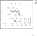
- the figure 2 schematically represents an example of device 1 according to the invention. It can be in the form of a housing, for example a housing with a volume less than that of a cigarette package.
- the case is intended to be put in the pocket. It is advantageously waterproof.
- the outside of the case may have an optional charging socket, for example a micro-USB or mini-USB or USD C type.
- the case is preferably free of charge.
- display except state LEDs 22, and any touch data input member, except an on-off button 24.
- An optional Bluetooth interface may be provided for the update and / or to communicate with a user.
- user device nearby, for example a smartphone or tablet of a user, used as a data entry terminal and display.
- the inside of the housing comprises an electronic circuit preferably mounted on a printed circuit not shown.
- the circuit comprises a low-power microprocessor 6, for example an ARM processor, accessing a memory 8.
- the memory 8 may include a semi-permanent memory, for example a flash memory, and a volatile memory of the RAM type.
- a portion of the memory 80 stores a unique user identifier, distinguishing the user holding the device 1 from all other users. This identifier is preferably used both for access control initiated via the RFID interface, for user location via the Wi-Fi interface, and for payments via the nfc interface.
- the processor 6 and the other components of the device 1 are powered by a battery 4, preferably a rechargeable battery, for example a Lithium-ion or Lithium-Polymer battery.
- the autonomy of the battery 4 is preferably greater than one week of normal use.
- the device 1 further comprises an active RFID circuit 10 powered by the battery 4 and controlled by the processor 6, in order to exchange data with an access control terminal 40.
- the RFID circuit may comprise means for identifying the device, preferably with the identity stored in the memory location 80, or with another identity.
- An anti-collision module may be provided in the RFID circuit 10 and / or in the access control terminal 40 in order to manage data collision problems between several devices 1 in a read zone 41. In a preferred embodiment, this module is however replaced by a one-way communication from the access control terminal 40 to the device 1, which minimizes the risk of collision.
- a cryptographic module may be provided to secure the communication between the RFID circuit and the access control terminal 40.
- the active RFID circuit 10 makes it possible in particular to initiate a user authentication process when it is with its device in the perimeter 41 around an access control terminal 40; the detection of a signal of the terminal then initiates the sending of the identity of the access control terminal 40 and the identifier of the device 1 to the server 70 which identifies the user, and checks or debits his account .
- the user identification is used by the server 70 to open an access gantry, to check the presence of authorized or unauthorized users in perimeters 41, and / or to bill that presence. This information can also be used by the server 70 to optimize the use of the park, including managing the queues and the distribution of users on the various infrastructures.
- the active RFID circuit 10 may also, or alternatively, be used to exit the device from a standby mode when it is in or near the leisure park, so that it can then be identified or located.
- Some users may be equipped with a passive transponder, for example in a smart card format, which makes it possible to signal to the access terminals the presence of an identified user in the associated access zone 41.
- the device 1 also comprises a wireless interface 12 in a frequency band above 10 MHz, for example 13.56 MHz, for example an interface according to the NFC protocol.
- This interface is intended to communicate with the payment terminal 30 to exchange payment data, for example in order to recharge a monetary amount associated with the device, or to debit it as and when the use of infrastructure.
- the device 1 further comprises a Wi-Fi interface 14 (for example 2.4 GHz) for receiving a Wi-Fi signal transmitted by the Wi-Fi terminals 50.
- This communication channel makes it possible on the one hand to exchange data with the server 7 or other Internet sites, for example for updates of the device 1, or for other value-added services.
- the Wi-Fi interface further comprises a circuit not shown for measuring, in several given times, a physical parameter of all Wi-Fi signals received at this time.
- the measured parameter can be, for example, the amplitude of the Wi-Fi signal, its phase, possibly the reception time (which makes it possible to determine the flight time from terminal 50), etc.
- This parameter is advantageously transmitted by Wi-Fi to the server 70 (or to a dedicated server) in order to determine by triangulation or trilateration the location of the device 1.
- the location could also be performed by the device itself, but this requires on the one hand a higher power consumption on the part of the device, and on the other hand an update in each device 1 active Wi-Fi terminal locations.
- This location is preferably carried out at regular intervals, for example every 5 minutes, at the request of the device 1.
- localization can also be triggered by different events detected in the device 1, for example the startup of the device 1, its output from a standby mode, and / or a displacement detected by the inertial sensor 18 or a shock sensor, described below.
- An on-demand localization triggered by the server 70 or by the user can also be performed.
- the device 1 advantageously comprises a standby circuit 16 which makes it possible to put all or at least some of the components of the device 1 on standby or partial when certain standby conditions are fulfilled.
- the device 1 advantageously comprises a sensor 18 already mentioned, for example a shock sensor, or an inertial sensor such as an accelerometer and / or a gyroscope, for detecting the movements of the device.
- the device 1 can be put on standby after a prolonged period of immobility, for example after 5 minutes of immobility. It can be awakened by an interruption generated by the sensor 18 in case of displacement of the latter, or amplitude displacement above a threshold, or with sufficient acceleration.
- the active RFID circuit 10 can also be woken by the active RFID circuit 10 when the device 1 is in the perimeter 41 of receiving a RFID signal transmitted by an access control terminal 40.
- the active RFID circuit 10 can be activated, at least intermittently, even when the rest of the device is in sleep mode.
- the standby circuit can also be put on standby by a clock circuit 20.
- the standby can for example be automatic at the times of closure of the leisure park.
- the clock circuit may also put the device 1, or some components of this device, in intermittent standby even during periods when it is used. For example, it is possible to put the processor 6 in standby mode, or at least in reduced power consumption mode, and then wake it up with periodic cycle times between 30 and 120 seconds.
- a sleep and / or wake-up button may also be provided on the housing of the device 1.
- the device can incorporate security means.
- a picture of the user is stored in the memory 8, which may be displayed near the access control terminal or by a controller with a suitable reader, to ensure that a device containing a personal subscription is used by the right user.
- the use of the device for example to program it or to load functions, can be protected by a password introduced for example in a connected device, for example a smartphone.
- Certain data stored in the memory for example electronic keys, can also be encrypted.
- the user moves to a payment terminal 30 to load a prepaid amount in his device, or to consult the balance available.
- This balance can advantageously also be displayed on a device connected to the device 1.
- charging via the Internet for example via the Wi-Fi interface, can also be performed.
- the user then accesses the leisure park, for example the ski area, which he uses the facilities 60. Its device 1 is then put out of sleep as soon as an RFID signal is received from one of the access control terminals 40 , or by another event such as shock detection, displacement, or periodically.
- server 70 checks the right of the user to access the installation near the zone 41, and possibly debits the user's monetary account.
- the accesses can also be checked for statistical purposes or queues control for example.
- the user When it is outside the perimeter 41 of reading access control terminals 40, the user is located periodically or on demand, thanks to Wi-Fi signals received throughout the park of several Wi-Fi terminals 50 distributed in the park.
- the location information is determined by the server 70 operated by the park manager, or by a third party offering this location service.
- This location can be made available to the user himself to allow him for example to move in the park. It is also possible for example to determine the position of his friends or family members who gave him this authorization.
- the position of the user can for example be displayed on a map shown on the display 22 of the device, or on a smartphone or other terminal connected via the Internet to the server 70.
- This location can also be made available to the operator of the leisure park to enable him to manage the movements of users according to the day or the season, and to adapt his offer accordingly.
- the park operator may also charge for use according to this location, for example depending on the distance traveled by a skier on the ski area.
- This location also allows him to locate users who are moving away from the domain, for example to ski off-piste.
- the location displayed for the park operator can be anonymised, for example by replacing the user's identity with an alias.
- This location can also be made available to service providers, for example restaurants, bars, car parks or other providers on the leisure park. This information enables them, for example, to adopt their offer and / or their rates according to the demand or the demand according to the location of the users.
- the location displayed for the park operator is preferably anonymised, for example by replacing the identity of the user with an alias.
- the server 70 can also manage a loyalty program.
- Fidelity points may for example be distributed as functions of the monetary sums loaded in the device.
- loyalty points may be distributed based on the location or trajectory traveled by a user. For example, loyalty points can be awarded to a user who has traveled a minimum distance per day, who has borrowed a certain number of facilities, and / or visited facilities of external providers.
- the server 70 can also manage a profile of each user, associating each user with more complete data than those stored in his device.
- This profile can for example include bibliographic data (name, surname, address, telephone number, e-mail address, payment details etc); preferences (preferred means of payment, favorite facilities, language, etc.), a history of transactions and travel, etc.
Landscapes
- Physics & Mathematics (AREA)
- General Physics & Mathematics (AREA)
- Mobile Radio Communication Systems (AREA)
Applications Claiming Priority (1)
| Application Number | Priority Date | Filing Date | Title |
|---|---|---|---|
| CH01313/17A CH714291A1 (fr) | 2017-10-31 | 2017-10-31 | Dispositif, système et procédé de contrôle d'accès, de paiement et de localisation. |
Publications (2)
| Publication Number | Publication Date |
|---|---|
| EP3477602A1 true EP3477602A1 (de) | 2019-05-01 |
| EP3477602B1 EP3477602B1 (de) | 2021-04-28 |
Family
ID=60301736
Family Applications (1)
| Application Number | Title | Priority Date | Filing Date |
|---|---|---|---|
| EP18203045.2A Active EP3477602B1 (de) | 2017-10-31 | 2018-10-29 | Kontrollvorrichtung, -system und -verfahren für zugriff, bezahlung und lokalisierung |
Country Status (2)
| Country | Link |
|---|---|
| EP (1) | EP3477602B1 (de) |
| CH (1) | CH714291A1 (de) |
Citations (5)
| Publication number | Priority date | Publication date | Assignee | Title |
|---|---|---|---|---|
| GB2469026A (en) * | 2009-03-30 | 2010-10-06 | Nec Europe Ltd | Information delivery method to registered terminals |
| US20130182382A1 (en) * | 2011-12-20 | 2013-07-18 | Techip International Limited | Tamper-alert resistant bands for human limbs and associated monitoring systems and methods |
| US20150081539A1 (en) * | 2013-09-19 | 2015-03-19 | Casio Computer Co., Ltd. | Information device, mobile device, and wearable information device |
| US20150091726A1 (en) * | 2013-08-06 | 2015-04-02 | Clemens Lindig | Method and system for providing location-based services |
| US20170270734A1 (en) * | 2016-03-16 | 2017-09-21 | Universal City Studios Llc | Virtual Queue System and Method |
-
2017
- 2017-10-31 CH CH01313/17A patent/CH714291A1/fr not_active Application Discontinuation
-
2018
- 2018-10-29 EP EP18203045.2A patent/EP3477602B1/de active Active
Patent Citations (5)
| Publication number | Priority date | Publication date | Assignee | Title |
|---|---|---|---|---|
| GB2469026A (en) * | 2009-03-30 | 2010-10-06 | Nec Europe Ltd | Information delivery method to registered terminals |
| US20130182382A1 (en) * | 2011-12-20 | 2013-07-18 | Techip International Limited | Tamper-alert resistant bands for human limbs and associated monitoring systems and methods |
| US20150091726A1 (en) * | 2013-08-06 | 2015-04-02 | Clemens Lindig | Method and system for providing location-based services |
| US20150081539A1 (en) * | 2013-09-19 | 2015-03-19 | Casio Computer Co., Ltd. | Information device, mobile device, and wearable information device |
| US20170270734A1 (en) * | 2016-03-16 | 2017-09-21 | Universal City Studios Llc | Virtual Queue System and Method |
Also Published As
| Publication number | Publication date |
|---|---|
| EP3477602B1 (de) | 2021-04-28 |
| CH714291A1 (fr) | 2019-05-15 |
Similar Documents
| Publication | Publication Date | Title |
|---|---|---|
| US12546143B2 (en) | Systems and methods for magnet-equipped locks | |
| WO2013132449A1 (en) | Payment/management system for electric cars' charging station | |
| EP2199966A1 (de) | Verfahren zur Sicherung von Transaktionen, entsprechende Transaktionsvorrichtung, entsprechender Bankserver, entsprechendes mobiles Endgerät und dazugehörige Computerprogrammprodukte | |
| EP3729383B1 (de) | Aggregator von identifikationsvorrichtungen | |
| WO2015015011A1 (fr) | Dispositif de paiement automatique a distance de consommations referencees dans le temps et l'espace | |
| US20190279147A1 (en) | System and Method for Control of Bailment Inventory | |
| WO2012110880A1 (en) | A device and system for vending value token | |
| EP3020220A1 (de) | Vorrichtung und verfahren zur steuerung des zugriffs auf mindestens eine maschine | |
| FR2968433A1 (fr) | Dispositif de paiement electronique apte a recevoir et maintenir un telephone portable. | |
| BE1025027B1 (fr) | Système de paiement pour station de recharge de voitures électriques | |
| EP3477602B1 (de) | Kontrollvorrichtung, -system und -verfahren für zugriff, bezahlung und lokalisierung | |
| EP3472794B1 (de) | System zur bereitstellung gemeinsam genutzter, an stationen festgemachter fahrzeuge und zugehörige vorrichtungen | |
| EP3642641A1 (de) | Geolokalisierung ohne gps mit einen gemischtem wifi- und lpwan-plotter | |
| FR3016993A1 (fr) | Procede de gestion de places libres de stationnement de vehicules et dispositif permettant la mise en oeuvre de ce procede | |
| FR3053512A1 (fr) | Procede de gestion de stationnement d'un vehicule | |
| WO2025125604A1 (fr) | Procédé de transaction « mains libres » à l'aide d'un terminal mobile | |
| EP3246846B1 (de) | Kommunikationssystem, leistungsversorgungssystem, das ein solches kommunikationssystem umfasst, und entsprechendes verfahren | |
| EP3383509A1 (de) | Vorrichtung zur optimierung des betriebs einer spiel- oder freizeitanlage | |
| KR20160054187A (ko) | 대중교통 이용정보 제공 시스템 | |
| FR3108996A1 (fr) | Attribution de droit par transmission d'onde radio en champ proche | |
| WO2017001674A1 (fr) | Procédé de gestion de l'utilisation d'un espace stationnement et dispositifs associés | |
| FR3089764A1 (fr) | Dispositif électronique de rangement d’au moins une carte à microprocesseur | |
| FR3094103A1 (fr) | Système d’affichage d’une consommation électrique, chargeur d’un tel système, procédé et programme de mise en œuvre d’un tel système |
Legal Events
| Date | Code | Title | Description |
|---|---|---|---|
| PUAI | Public reference made under article 153(3) epc to a published international application that has entered the european phase |
Free format text: ORIGINAL CODE: 0009012 |
|
| STAA | Information on the status of an ep patent application or granted ep patent |
Free format text: STATUS: THE APPLICATION HAS BEEN PUBLISHED |
|
| AK | Designated contracting states |
Kind code of ref document: A1 Designated state(s): AL AT BE BG CH CY CZ DE DK EE ES FI FR GB GR HR HU IE IS IT LI LT LU LV MC MK MT NL NO PL PT RO RS SE SI SK SM TR |
|
| AX | Request for extension of the european patent |
Extension state: BA ME |
|
| STAA | Information on the status of an ep patent application or granted ep patent |
Free format text: STATUS: REQUEST FOR EXAMINATION WAS MADE |
|
| 17P | Request for examination filed |
Effective date: 20191101 |
|
| RBV | Designated contracting states (corrected) |
Designated state(s): AL AT BE BG CH CY CZ DE DK EE ES FI FR GB GR HR HU IE IS IT LI LT LU LV MC MK MT NL NO PL PT RO RS SE SI SK SM TR |
|
| REG | Reference to a national code |
Ref country code: DE Ref legal event code: R079 Ref document number: 602018016132 Country of ref document: DE Free format text: PREVIOUS MAIN CLASS: G07C0009000000 Ipc: G07C0011000000 |
|
| GRAP | Despatch of communication of intention to grant a patent |
Free format text: ORIGINAL CODE: EPIDOSNIGR1 |
|
| STAA | Information on the status of an ep patent application or granted ep patent |
Free format text: STATUS: GRANT OF PATENT IS INTENDED |
|
| RIC1 | Information provided on ipc code assigned before grant |
Ipc: G07C 9/28 20200101ALI20201013BHEP Ipc: G07C 11/00 20060101AFI20201013BHEP |
|
| INTG | Intention to grant announced |
Effective date: 20201029 |
|
| GRAS | Grant fee paid |
Free format text: ORIGINAL CODE: EPIDOSNIGR3 |
|
| RAP1 | Party data changed (applicant data changed or rights of an application transferred) |
Owner name: E-LIBERTY SERVICES SA |
|
| GRAA | (expected) grant |
Free format text: ORIGINAL CODE: 0009210 |
|
| STAA | Information on the status of an ep patent application or granted ep patent |
Free format text: STATUS: THE PATENT HAS BEEN GRANTED |
|
| AK | Designated contracting states |
Kind code of ref document: B1 Designated state(s): AL AT BE BG CH CY CZ DE DK EE ES FI FR GB GR HR HU IE IS IT LI LT LU LV MC MK MT NL NO PL PT RO RS SE SI SK SM TR |
|
| REG | Reference to a national code |
Ref country code: GB Ref legal event code: FG4D Free format text: NOT ENGLISH |
|
| REG | Reference to a national code |
Ref country code: CH Ref legal event code: EP |
|
| REG | Reference to a national code |
Ref country code: CH Ref legal event code: NV Representative=s name: P&TS SA, CH |
|
| REG | Reference to a national code |
Ref country code: AT Ref legal event code: REF Ref document number: 1387959 Country of ref document: AT Kind code of ref document: T Effective date: 20210515 |
|
| REG | Reference to a national code |
Ref country code: DE Ref legal event code: R096 Ref document number: 602018016132 Country of ref document: DE |
|
| REG | Reference to a national code |
Ref country code: IE Ref legal event code: FG4D Free format text: LANGUAGE OF EP DOCUMENT: FRENCH |
|
| REG | Reference to a national code |
Ref country code: LT Ref legal event code: MG9D |
|
| PG25 | Lapsed in a contracting state [announced via postgrant information from national office to epo] |
Ref country code: FI Free format text: LAPSE BECAUSE OF FAILURE TO SUBMIT A TRANSLATION OF THE DESCRIPTION OR TO PAY THE FEE WITHIN THE PRESCRIBED TIME-LIMIT Effective date: 20210428 Ref country code: LT Free format text: LAPSE BECAUSE OF FAILURE TO SUBMIT A TRANSLATION OF THE DESCRIPTION OR TO PAY THE FEE WITHIN THE PRESCRIBED TIME-LIMIT Effective date: 20210428 Ref country code: HR Free format text: LAPSE BECAUSE OF FAILURE TO SUBMIT A TRANSLATION OF THE DESCRIPTION OR TO PAY THE FEE WITHIN THE PRESCRIBED TIME-LIMIT Effective date: 20210428 Ref country code: NL Free format text: LAPSE BECAUSE OF FAILURE TO SUBMIT A TRANSLATION OF THE DESCRIPTION OR TO PAY THE FEE WITHIN THE PRESCRIBED TIME-LIMIT Effective date: 20210428 Ref country code: BG Free format text: LAPSE BECAUSE OF FAILURE TO SUBMIT A TRANSLATION OF THE DESCRIPTION OR TO PAY THE FEE WITHIN THE PRESCRIBED TIME-LIMIT Effective date: 20210728 |
|
| PG25 | Lapsed in a contracting state [announced via postgrant information from national office to epo] |
Ref country code: GR Free format text: LAPSE BECAUSE OF FAILURE TO SUBMIT A TRANSLATION OF THE DESCRIPTION OR TO PAY THE FEE WITHIN THE PRESCRIBED TIME-LIMIT Effective date: 20210729 Ref country code: IS Free format text: LAPSE BECAUSE OF FAILURE TO SUBMIT A TRANSLATION OF THE DESCRIPTION OR TO PAY THE FEE WITHIN THE PRESCRIBED TIME-LIMIT Effective date: 20210828 Ref country code: NO Free format text: LAPSE BECAUSE OF FAILURE TO SUBMIT A TRANSLATION OF THE DESCRIPTION OR TO PAY THE FEE WITHIN THE PRESCRIBED TIME-LIMIT Effective date: 20210728 Ref country code: LV Free format text: LAPSE BECAUSE OF FAILURE TO SUBMIT A TRANSLATION OF THE DESCRIPTION OR TO PAY THE FEE WITHIN THE PRESCRIBED TIME-LIMIT Effective date: 20210428 Ref country code: PL Free format text: LAPSE BECAUSE OF FAILURE TO SUBMIT A TRANSLATION OF THE DESCRIPTION OR TO PAY THE FEE WITHIN THE PRESCRIBED TIME-LIMIT Effective date: 20210428 Ref country code: PT Free format text: LAPSE BECAUSE OF FAILURE TO SUBMIT A TRANSLATION OF THE DESCRIPTION OR TO PAY THE FEE WITHIN THE PRESCRIBED TIME-LIMIT Effective date: 20210830 Ref country code: SE Free format text: LAPSE BECAUSE OF FAILURE TO SUBMIT A TRANSLATION OF THE DESCRIPTION OR TO PAY THE FEE WITHIN THE PRESCRIBED TIME-LIMIT Effective date: 20210428 Ref country code: RS Free format text: LAPSE BECAUSE OF FAILURE TO SUBMIT A TRANSLATION OF THE DESCRIPTION OR TO PAY THE FEE WITHIN THE PRESCRIBED TIME-LIMIT Effective date: 20210428 |
|
| REG | Reference to a national code |
Ref country code: NL Ref legal event code: MP Effective date: 20210428 |
|
| PG25 | Lapsed in a contracting state [announced via postgrant information from national office to epo] |
Ref country code: SM Free format text: LAPSE BECAUSE OF FAILURE TO SUBMIT A TRANSLATION OF THE DESCRIPTION OR TO PAY THE FEE WITHIN THE PRESCRIBED TIME-LIMIT Effective date: 20210428 Ref country code: SK Free format text: LAPSE BECAUSE OF FAILURE TO SUBMIT A TRANSLATION OF THE DESCRIPTION OR TO PAY THE FEE WITHIN THE PRESCRIBED TIME-LIMIT Effective date: 20210428 Ref country code: EE Free format text: LAPSE BECAUSE OF FAILURE TO SUBMIT A TRANSLATION OF THE DESCRIPTION OR TO PAY THE FEE WITHIN THE PRESCRIBED TIME-LIMIT Effective date: 20210428 Ref country code: ES Free format text: LAPSE BECAUSE OF FAILURE TO SUBMIT A TRANSLATION OF THE DESCRIPTION OR TO PAY THE FEE WITHIN THE PRESCRIBED TIME-LIMIT Effective date: 20210428 Ref country code: CZ Free format text: LAPSE BECAUSE OF FAILURE TO SUBMIT A TRANSLATION OF THE DESCRIPTION OR TO PAY THE FEE WITHIN THE PRESCRIBED TIME-LIMIT Effective date: 20210428 Ref country code: DK Free format text: LAPSE BECAUSE OF FAILURE TO SUBMIT A TRANSLATION OF THE DESCRIPTION OR TO PAY THE FEE WITHIN THE PRESCRIBED TIME-LIMIT Effective date: 20210428 Ref country code: RO Free format text: LAPSE BECAUSE OF FAILURE TO SUBMIT A TRANSLATION OF THE DESCRIPTION OR TO PAY THE FEE WITHIN THE PRESCRIBED TIME-LIMIT Effective date: 20210428 |
|
| REG | Reference to a national code |
Ref country code: DE Ref legal event code: R097 Ref document number: 602018016132 Country of ref document: DE |
|
| PLBE | No opposition filed within time limit |
Free format text: ORIGINAL CODE: 0009261 |
|
| STAA | Information on the status of an ep patent application or granted ep patent |
Free format text: STATUS: NO OPPOSITION FILED WITHIN TIME LIMIT |
|
| 26N | No opposition filed |
Effective date: 20220131 |
|
| PG25 | Lapsed in a contracting state [announced via postgrant information from national office to epo] |
Ref country code: IS Free format text: LAPSE BECAUSE OF FAILURE TO SUBMIT A TRANSLATION OF THE DESCRIPTION OR TO PAY THE FEE WITHIN THE PRESCRIBED TIME-LIMIT Effective date: 20210828 Ref country code: AL Free format text: LAPSE BECAUSE OF FAILURE TO SUBMIT A TRANSLATION OF THE DESCRIPTION OR TO PAY THE FEE WITHIN THE PRESCRIBED TIME-LIMIT Effective date: 20210428 |
|
| REG | Reference to a national code |
Ref country code: BE Ref legal event code: MM Effective date: 20211031 |
|
| PG25 | Lapsed in a contracting state [announced via postgrant information from national office to epo] |
Ref country code: MC Free format text: LAPSE BECAUSE OF FAILURE TO SUBMIT A TRANSLATION OF THE DESCRIPTION OR TO PAY THE FEE WITHIN THE PRESCRIBED TIME-LIMIT Effective date: 20210428 |
|
| PG25 | Lapsed in a contracting state [announced via postgrant information from national office to epo] |
Ref country code: LU Free format text: LAPSE BECAUSE OF NON-PAYMENT OF DUE FEES Effective date: 20211029 Ref country code: IT Free format text: LAPSE BECAUSE OF FAILURE TO SUBMIT A TRANSLATION OF THE DESCRIPTION OR TO PAY THE FEE WITHIN THE PRESCRIBED TIME-LIMIT Effective date: 20210428 Ref country code: BE Free format text: LAPSE BECAUSE OF NON-PAYMENT OF DUE FEES Effective date: 20211031 |
|
| PG25 | Lapsed in a contracting state [announced via postgrant information from national office to epo] |
Ref country code: IE Free format text: LAPSE BECAUSE OF NON-PAYMENT OF DUE FEES Effective date: 20211029 |
|
| GBPC | Gb: european patent ceased through non-payment of renewal fee |
Effective date: 20221029 |
|
| PG25 | Lapsed in a contracting state [announced via postgrant information from national office to epo] |
Ref country code: CY Free format text: LAPSE BECAUSE OF FAILURE TO SUBMIT A TRANSLATION OF THE DESCRIPTION OR TO PAY THE FEE WITHIN THE PRESCRIBED TIME-LIMIT Effective date: 20210428 |
|
| PG25 | Lapsed in a contracting state [announced via postgrant information from national office to epo] |
Ref country code: HU Free format text: LAPSE BECAUSE OF FAILURE TO SUBMIT A TRANSLATION OF THE DESCRIPTION OR TO PAY THE FEE WITHIN THE PRESCRIBED TIME-LIMIT; INVALID AB INITIO Effective date: 20181029 |
|
| PG25 | Lapsed in a contracting state [announced via postgrant information from national office to epo] |
Ref country code: GB Free format text: LAPSE BECAUSE OF NON-PAYMENT OF DUE FEES Effective date: 20221029 |
|
| PG25 | Lapsed in a contracting state [announced via postgrant information from national office to epo] |
Ref country code: MK Free format text: LAPSE BECAUSE OF FAILURE TO SUBMIT A TRANSLATION OF THE DESCRIPTION OR TO PAY THE FEE WITHIN THE PRESCRIBED TIME-LIMIT Effective date: 20210428 |
|
| PG25 | Lapsed in a contracting state [announced via postgrant information from national office to epo] |
Ref country code: TR Free format text: LAPSE BECAUSE OF FAILURE TO SUBMIT A TRANSLATION OF THE DESCRIPTION OR TO PAY THE FEE WITHIN THE PRESCRIBED TIME-LIMIT Effective date: 20210428 |
|
| PG25 | Lapsed in a contracting state [announced via postgrant information from national office to epo] |
Ref country code: MT Free format text: LAPSE BECAUSE OF FAILURE TO SUBMIT A TRANSLATION OF THE DESCRIPTION OR TO PAY THE FEE WITHIN THE PRESCRIBED TIME-LIMIT Effective date: 20210428 |
|
| REG | Reference to a national code |
Ref country code: AT Ref legal event code: UEP Ref document number: 1387959 Country of ref document: AT Kind code of ref document: T Effective date: 20210428 |
|
| REG | Reference to a national code |
Ref country code: CH Ref legal event code: U11 Free format text: ST27 STATUS EVENT CODE: U-0-0-U10-U11 (AS PROVIDED BY THE NATIONAL OFFICE) Effective date: 20251101 |
|
| PGFP | Annual fee paid to national office [announced via postgrant information from national office to epo] |
Ref country code: DE Payment date: 20251021 Year of fee payment: 8 |
|
| PGFP | Annual fee paid to national office [announced via postgrant information from national office to epo] |
Ref country code: AT Payment date: 20251022 Year of fee payment: 8 |
|
| PGFP | Annual fee paid to national office [announced via postgrant information from national office to epo] |
Ref country code: FR Payment date: 20251030 Year of fee payment: 8 |
|
| PGFP | Annual fee paid to national office [announced via postgrant information from national office to epo] |
Ref country code: CH Payment date: 20251101 Year of fee payment: 8 |