EP3477671B1 - Condensateur hybride et procédé de fabrication de celui-ci - Google Patents
Condensateur hybride et procédé de fabrication de celui-ci Download PDFInfo
- Publication number
- EP3477671B1 EP3477671B1 EP17815299.7A EP17815299A EP3477671B1 EP 3477671 B1 EP3477671 B1 EP 3477671B1 EP 17815299 A EP17815299 A EP 17815299A EP 3477671 B1 EP3477671 B1 EP 3477671B1
- Authority
- EP
- European Patent Office
- Prior art keywords
- active material
- electrode active
- negative electrode
- metal compound
- compound particles
- Prior art date
- Legal status (The legal status is an assumption and is not a legal conclusion. Google has not performed a legal analysis and makes no representation as to the accuracy of the status listed.)
- Active
Links
Images





Classifications
-
- H—ELECTRICITY
- H01—ELECTRIC ELEMENTS
- H01G—CAPACITORS; CAPACITORS, RECTIFIERS, DETECTORS, SWITCHING DEVICES, LIGHT-SENSITIVE OR TEMPERATURE-SENSITIVE DEVICES OF THE ELECTROLYTIC TYPE
- H01G11/00—Hybrid capacitors, i.e. capacitors having different positive and negative electrodes; Electric double-layer [EDL] capacitors; Processes for the manufacture thereof or of parts thereof
- H01G11/04—Hybrid capacitors
- H01G11/06—Hybrid capacitors with one of the electrodes allowing ions to be reversibly doped thereinto, e.g. lithium ion capacitors [LIC]
-
- H—ELECTRICITY
- H01—ELECTRIC ELEMENTS
- H01G—CAPACITORS; CAPACITORS, RECTIFIERS, DETECTORS, SWITCHING DEVICES, LIGHT-SENSITIVE OR TEMPERATURE-SENSITIVE DEVICES OF THE ELECTROLYTIC TYPE
- H01G11/00—Hybrid capacitors, i.e. capacitors having different positive and negative electrodes; Electric double-layer [EDL] capacitors; Processes for the manufacture thereof or of parts thereof
- H01G11/22—Electrodes
- H01G11/24—Electrodes characterised by structural features of the materials making up or comprised in the electrodes, e.g. form, surface area or porosity; characterised by the structural features of powders or particles used therefor
-
- H—ELECTRICITY
- H01—ELECTRIC ELEMENTS
- H01G—CAPACITORS; CAPACITORS, RECTIFIERS, DETECTORS, SWITCHING DEVICES, LIGHT-SENSITIVE OR TEMPERATURE-SENSITIVE DEVICES OF THE ELECTROLYTIC TYPE
- H01G11/00—Hybrid capacitors, i.e. capacitors having different positive and negative electrodes; Electric double-layer [EDL] capacitors; Processes for the manufacture thereof or of parts thereof
- H01G11/22—Electrodes
- H01G11/26—Electrodes characterised by their structure, e.g. multi-layered, porosity or surface features
- H01G11/28—Electrodes characterised by their structure, e.g. multi-layered, porosity or surface features arranged or disposed on a current collector; Layers or phases between electrodes and current collectors, e.g. adhesives
-
- H—ELECTRICITY
- H01—ELECTRIC ELEMENTS
- H01G—CAPACITORS; CAPACITORS, RECTIFIERS, DETECTORS, SWITCHING DEVICES, LIGHT-SENSITIVE OR TEMPERATURE-SENSITIVE DEVICES OF THE ELECTROLYTIC TYPE
- H01G11/00—Hybrid capacitors, i.e. capacitors having different positive and negative electrodes; Electric double-layer [EDL] capacitors; Processes for the manufacture thereof or of parts thereof
- H01G11/22—Electrodes
- H01G11/30—Electrodes characterised by their material
- H01G11/32—Carbon-based
-
- H—ELECTRICITY
- H01—ELECTRIC ELEMENTS
- H01G—CAPACITORS; CAPACITORS, RECTIFIERS, DETECTORS, SWITCHING DEVICES, LIGHT-SENSITIVE OR TEMPERATURE-SENSITIVE DEVICES OF THE ELECTROLYTIC TYPE
- H01G11/00—Hybrid capacitors, i.e. capacitors having different positive and negative electrodes; Electric double-layer [EDL] capacitors; Processes for the manufacture thereof or of parts thereof
- H01G11/22—Electrodes
- H01G11/30—Electrodes characterised by their material
- H01G11/32—Carbon-based
- H01G11/42—Powders or particles, e.g. composition thereof
-
- H—ELECTRICITY
- H01—ELECTRIC ELEMENTS
- H01G—CAPACITORS; CAPACITORS, RECTIFIERS, DETECTORS, SWITCHING DEVICES, LIGHT-SENSITIVE OR TEMPERATURE-SENSITIVE DEVICES OF THE ELECTROLYTIC TYPE
- H01G11/00—Hybrid capacitors, i.e. capacitors having different positive and negative electrodes; Electric double-layer [EDL] capacitors; Processes for the manufacture thereof or of parts thereof
- H01G11/22—Electrodes
- H01G11/30—Electrodes characterised by their material
- H01G11/46—Metal oxides
-
- H—ELECTRICITY
- H01—ELECTRIC ELEMENTS
- H01G—CAPACITORS; CAPACITORS, RECTIFIERS, DETECTORS, SWITCHING DEVICES, LIGHT-SENSITIVE OR TEMPERATURE-SENSITIVE DEVICES OF THE ELECTROLYTIC TYPE
- H01G11/00—Hybrid capacitors, i.e. capacitors having different positive and negative electrodes; Electric double-layer [EDL] capacitors; Processes for the manufacture thereof or of parts thereof
- H01G11/22—Electrodes
- H01G11/30—Electrodes characterised by their material
- H01G11/50—Electrodes characterised by their material specially adapted for lithium-ion capacitors, e.g. for lithium-doping or for intercalation
-
- H—ELECTRICITY
- H01—ELECTRIC ELEMENTS
- H01G—CAPACITORS; CAPACITORS, RECTIFIERS, DETECTORS, SWITCHING DEVICES, LIGHT-SENSITIVE OR TEMPERATURE-SENSITIVE DEVICES OF THE ELECTROLYTIC TYPE
- H01G11/00—Hybrid capacitors, i.e. capacitors having different positive and negative electrodes; Electric double-layer [EDL] capacitors; Processes for the manufacture thereof or of parts thereof
- H01G11/84—Processes for the manufacture of hybrid or EDL capacitors, or components thereof
- H01G11/86—Processes for the manufacture of hybrid or EDL capacitors, or components thereof specially adapted for electrodes
-
- H—ELECTRICITY
- H01—ELECTRIC ELEMENTS
- H01G—CAPACITORS; CAPACITORS, RECTIFIERS, DETECTORS, SWITCHING DEVICES, LIGHT-SENSITIVE OR TEMPERATURE-SENSITIVE DEVICES OF THE ELECTROLYTIC TYPE
- H01G11/00—Hybrid capacitors, i.e. capacitors having different positive and negative electrodes; Electric double-layer [EDL] capacitors; Processes for the manufacture thereof or of parts thereof
- H01G11/66—Current collectors
- H01G11/68—Current collectors characterised by their material
-
- Y—GENERAL TAGGING OF NEW TECHNOLOGICAL DEVELOPMENTS; GENERAL TAGGING OF CROSS-SECTIONAL TECHNOLOGIES SPANNING OVER SEVERAL SECTIONS OF THE IPC; TECHNICAL SUBJECTS COVERED BY FORMER USPC CROSS-REFERENCE ART COLLECTIONS [XRACs] AND DIGESTS
- Y02—TECHNOLOGIES OR APPLICATIONS FOR MITIGATION OR ADAPTATION AGAINST CLIMATE CHANGE
- Y02E—REDUCTION OF GREENHOUSE GAS [GHG] EMISSIONS, RELATED TO ENERGY GENERATION, TRANSMISSION OR DISTRIBUTION
- Y02E60/00—Enabling technologies; Technologies with a potential or indirect contribution to GHG emissions mitigation
- Y02E60/13—Energy storage using capacitors
Definitions
- the present disclosure relates to a hybrid capacitor including a negative electrode that can occlude and release lithium ions and a positive electrode having an electrical double-layer capacitance and a manufacturing method thereof.
- An electrical double-layer capacitor including a positive electrode and a negative electrode which mainly include activated carbon is charged and discharged when cations and anions in an electrolytic solution are adsorbed to or released from activated carbon.
- the electrical double-layer capacitor is able to be rapidly charged and discharged, and has excellent output characteristics and excellent cycle characteristics, but it has a low energy density.
- a lithium secondary battery in which a material that can occlude and release lithium ions is used as a positive electrode active material and a negative electrode active material is charged when lithium ions are moved from the positive electrode to the negative electrode and is discharged when lithium ions are moved from the negative electrode to the positive electrode. While lithium ion secondary batteries can operate at a high voltage and have a large energy density, rapid charging and discharging are difficult, and there is also a problem of the reliability of a charging and discharging cycle.
- the hybrid capacitor includes a positive electrode including an active material having an electrical double-layer capacitance and a negative electrode including an active material that can occlude and release lithium ions, and has advantages of both the electrical double-layer capacitor and the lithium ion secondary battery. That is, the hybrid capacitor has a high energy density and excellent input and output characteristics.
- Patent literature WO 2012/169331 A1 discloses a lithium titanate particle active material which is capable of increasing cycle characteristics and electrical capacity during high-rate charging and discharging.
- patent literature US 2014/328005 A1 discloses a lithium titanium oxide/ carbon composite, a preparation method for the lithium titanium oxide/ carbon composite, a negative electrode material using the lithium titanium oxide/ carbon composite, and a hybrid super capacitor using the negative electrode material.
- the scientific publication of Smith et al. titled “Electrodes based on Magneli phase titanium oxides: the properties and applications of Ebonex materials discloses uses of Magneli phase titanium oxide material materials such as battery materials as they exhibit a conductivity comparable to that of graphite.
- a discharging capacity magnification of a negative electrode active material a discharging capacity of 100% of lithium titanate as a negative electrode active material is 2.2 to 7.0 times a discharging capacity of 100% of activated carbon as a positive electrode active material (for example, refer to Patent Document 3) .
- a discharging capacity magnification of the negative electrode active material when a discharging capacity magnification of the negative electrode active material is lowered, in other words, when a utilization ratio of the negative electrode active material, that is, a proportion of the negative electrode active material used during charging and discharging, increases, it is necessary for lithium ions to be diffused to deep parts of lithium titanate particles and a reactive surface area is reduced and a reaction resistance increases, and thus a DCIR increases.
- a discharging capacity magnification of the negative electrode active material increases, that is, when a utilization ratio of the negative electrode active material decreases, lithium ions are diffused near the surface of lithium titanate particles, and a reactive surface area increases, and thus a DCIR can be reduced. Therefore, a range in which a low DCIR is maintained is proposed.
- a utilization ratio of a negative electrode active material low is a problem in consideration of capacity increase and cost reduction for a capacitor. That is, since an amount of the negative electrode active material increases, the size of the negative electrode increases and a capacity per unit volume decreases. Therefore, in order to obtain a large capacity, the size of the capacitor increases, and in order to reduce the size of the capacitor, a low capacity is unavoidable. In addition, a large amount of a negative electrode active material is necessary, which results in high cost.
- An objective of the present invention is to provide a hybrid capacitor which increases a utilization ratio of a negative electrode active material and has a low direct current internal resistance, and a manufacturing method thereof.
- the invention is defined by the appended independent claim. Embodiments are set forth in the appended dependent claims and in the following description and drawings.
- Increasing a utilization ratio of a negative electrode active material means that lithium ions are diffused into deep parts of particles of the negative electrode active material and a diffusion distance of lithium ions increases. When a diffusion distance of lithium ions is longer, the direct current internal resistance increases. In addition, since a reactive surface area of the negative electrode active material decreases, the reaction resistance increases and the direct current internal resistance increases. Therefore, generally, the direct current internal resistance would increase according to an increase in the utilization ratio of the negative electrode active material.
- the inventors found that, when metal compound particles having a three-dimensional network structure are used as a negative electrode active material that can occlude and release lithium ions, surprisingly, even if the utilization ratio of the negative electrode active material increases, an increase in the direct current internal resistance is reduced.
- the metal compound particles may include less than 5 weight% carbon with respect to the metal compound particles .
- a differential pore volume in a pore size range of 10 to 40 nm may have a value of 0.01 cm 3 /g or more.
- the metal compound particles are typically lithium titanate.
- the metal compound particles have a three-dimensional network structure in which crystallites of lithium titanate are connected to each other, and a Magneli phase may be formed on a part of the surfaces of the crystallites.
- the positive electrode active material may be typically activated carbon.
- the metal compound particles may include less than 5 weight% the residual carbon.
- a positive electrode is a polarizable electrode having an electrical double-layer capacitance
- a negative electrode is a Faraday reaction electrode that can occlude and release lithium ions.
- the positive electrode and the negative electrode face each other with a separator therebetween.
- the positive electrode, the negative electrode, and the separator constitute a capacitor element.
- An electrolytic solution is impregnated into the capacitor element.
- the positive electrode is formed by supporting a positive electrode active material on a current collector.
- the negative electrode is formed by supporting a negative electrode active material on a current collector.
- the positive electrode active material is molded and bonded to the current collector.
- the negative electrode active material is molded and bonded to the current collector.
- the positive electrode active material and the current collector, and the negative electrode active material and the current collector are bonded respectively via a binder using pressure bonding, a doctor blade method, or the like.
- the current collector is, typically, a conductive material such as aluminum, copper, iron, nickel, titanium, steel, and carbon. In particular, aluminum or copper having high thermal conductivity and electron conductivity is preferable.
- a conductive material such as aluminum, copper, iron, nickel, titanium, steel, and carbon.
- aluminum or copper having high thermal conductivity and electron conductivity is preferable.
- any shape such as a film shape, a foil shape, a plate shape, a net shape, an expanded metal shape, or a cylindrical shape can be used.
- the binder examples include rubbers such as a fluorine type rubber, a diene type rubber, and a styrene type rubber, a fluorine-containing polymer such as polytetrafluoroethylene and polyvinylidene fluoride, celluloses such as carboxymethyl cellulose, and nitrocellulose, and additionally, a polyolefin resin, a polyimide resin, an acrylic resin, a nitrile resin, a polyester resin, a phenol resin, a polyvinyl acetate resin, a polyvinyl alcohol resin, and an epoxy resin. These binders may be used alone, or a mixture of two or more thereof may be used.
- the positive electrode active material mainly includes a carbon material, and the carbon material has a porous structure or a fibrous structure, and has an electrical double-layer capacitance.
- the carbon material may be subjected to an opening treatment or an activation treatment.
- An appropriate amount of a conductive additive may be mixed into a layer of the positive electrode active material as necessary.
- the carbon material as the positive electrode active material is a single material selected from among the following materials or a mixture of a plurality of types thereof.
- typical examples of the positive electrode active material having a porous structure include natural plant tissues such as coconut shell, synthetic resins such as phenol, activated carbon made from a source material derived from fossil fuels such as coal, coke, and pitch, carbon black such as Ketchen black, acetylene black, and channel black, carbon nanohorn, amorphous carbon, natural graphite, artificial graphite, graphitized Ketchen black, and mesoporous carbon.
- Typical examples of the positive electrode active material having a fibrous structure include carbon nanotubes and carbon nanofibers.
- the negative electrode active material is metal compound particles that can occlude and release lithium ions .
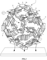
- the negative electrode active material has a three-dimensional network structure 1.
- nanosized primary particles 2 are connected to each other and continuous in a mesh form and nanosized voids 3 exist. There is no grain boundary at a binding interface of the primary particles 2, and on the other hand, there are many fine pores between the primary particles 2.
- the three-dimensional network structure 1 forms an electron path, the voids 3 become a storage space of an electrolytic solution, and pores between the primary particles 2 are considered to become a path of ions.
- metal compound particles used as the negative electrode active material include oxides such as FeO, Fe 2 O 3 , Fe 3 O 4 , MnO, MnO 2 , Mn 2 O 3 , Mn 3 O 4 , CoO, CO 3 O 4 , NiO, Ni 2 O 3 , TiO, TiO 2 , TiO 2 (B), CuO, NiO, SnO, SnO 2 , SiO 2 , RuO 2 , WO, WO 2 , WO 3 , MoO 3 , and ZnO, metals such as Sn, Si, Al, and Zn, composite oxides such as LiVO 2 , Li 3 VO 4 , Li 4 Ti 5 O 12 , Sc 2 TiO 5 , and Fe 2 TiO 5 , nitrides such as Li 2.6 Co 0.4 N, Ge 3 N 4 , Zn 3 N 2 , and Cu 3 N, Y 2 Ti 2 O 5 S 2 , and MoS 2 .
- lithium titanate (Li 4 Ti 5 ) lithium
- the porosity in a cross section of the three-dimensional network structure is preferably in a range of 7 to 50%.
- the porosity is less than 7%, an area in contact with an electrolytic solution is small, which influences the movement of ions in an electrolytic solution.
- the porosity exceeds 50%, bonds between primary particles become sparse, and it is difficult to form a three-dimensional network structure.
- An average particle size of primary particles is in a range of 5 to 300 nm.
- a method of calculating an average particle size is as follows. That is, the primary particles 2 are observed using a scanning electron microscope, an image including at least 150 primary particles or more is captured, a major diameter and a short diameter of an elliptical image of the primary particles 2 included in the captured single field of view (image) are measured, an average value of the major diameter and the minor diameter is calculated for each of the primary particles 2, average values of the primary particles 2 are summed, and the sum value is divided by the number of measured primary particles 2. The result falls within a range of 5 to 300 nm.
- metal compound particles When primary particles in this range are bonded to form a three-dimensional network structure, metal compound particles acquire many nanosized pores, an area of metal compound particles in contact with an electrolytic solution increases, and the movement of ions in an electrolytic solution becomes smooth. In addition, when pores of the metal compound particles are measured, there are many fine pores. In particular, many fine pores of 40 nm or less are included.
- a differential pore volume in a pore size range of 10 to 40 nm has a value of 0.01 cm 3 /g or more and particularly has a value of 0.02 cm 3 /g or more, and an area in contact with the electrolytic solution is high.
- an area in contact with the electrolytic solution is larger, a discharging rate characteristic when used for a negative electrode is improved.
- adhered carbon remains.
- An amount of adhered carbon is preferably less than 5 weight% with respect to the metal compound particles. Within this range, a decrease in the energy density due to the presence of carbon can be reduced. In particular, an amount of adhered carbon is preferably less than 1 weight% with respect to the metal compound particles. When an amount of carbon is limited to a very small amount, a reaction between carbon and an electrolytic solution in the negative electrode is restricted and storage characteristics are improved.
- the primary particles 2 of the metal compound particles are more preferably crystallites of which a part of the surface has a Magneli phase 2a.
- a crystallite is the largest aggregation that can be regarded as a single crystal of a metal compound. Crystallites are randomly oriented and bonded to each other on surfaces such as a flat surface and an end surface, and have pores 4 in some places.
- a crystallite has a flat plate shape
- a three-dimensional network structure is a card house structure.
- the surface of the crystallite is an edge surface and an edge or an end of a faceted surface.
- the surface of the crystallite is a single or a plurality of partial regions thereof.
- the crystallite has a flat plate shape such as a triangle, a rectangle or other polygonal shapes, a polyhedron shape with a thickness, or a shape formed in a sphere, an ellipsoid, or other curved surface.
- a spinel type lithium titanate represented by Li 4+w Ti 5 O 12 (0 ⁇ w ⁇ 3) or a Ramsdellite type lithium titanate represented by Li 2+y Ti 3 O 7 (0 ⁇ y ⁇ 3) can be used as metal compound particles constituting a three-dimensional network structure by crystallites having a Magneli phase.
- AMagneli phase is generated when one or more of edges or ends of crystallites are altered or when a part of the full length of edges or ends of crystallites or the full length thereof is altered.
- a Magneli phase may be included not only in edges or ends, but also in a partial region on the center part of the faceted surface.
- AMagneli phase is a titanium oxide represented by a general formula Ti n O 2n-1 (3 ⁇ n ⁇ 10) .
- the Magneli phase 2a is, for example, Ti 4 O 7 , a mixed phase of Ti 4 O 7 and Ti 5 O 9 , or any single substance selected from among compounds represented by a general formula Ti n O 2n-1 (3 ⁇ n ⁇ 10) or a mixed phase of two or more thereof.
- the negative electrode active material formed of lithium titanate has both characteristics of lithium titanate and characteristics of a Magneli phase.
- Lithium titanate has an energy storage function according to insertion and release of lithium ions. Since a change in the volume due to this insertion and release is about 1%, capacity deterioration is low. Since a charging and discharging potential is about 1.55 V (vs. Li/Li + ), side reactions such as decomposition of an electrolytic solution and precipitation of the metal lithium due to rapid charging and discharging are unlikely to occur, and cycle characteristics are excellent.
- the Magneli phase has high electrical conductivity, and Ti 4 O 7 has an electrical conductivity of about 2.75 times that of carbon. That is, the negative electrode active material has a characteristic that high electrical conductivity is additionally imparted by a Magneli phase, while the performance of the active material as lithium titanate is maintained.
- the negative electrode active material has a three-dimensional network structure in which a Magneli phase with high electrical conductivity is present on the surface of crystallites, and the crystallites are connected on surfaces such as a flat surface and an end surface. Therefore, the crystallites are partially connected via Magneli phases.
- Connection forms include a case in which Magneli phases are connected to each other, a case in which a Magneli phase and a surface other than a Magneli phase are connected to each other, and a combination of thereof. Accordingly, in the negative electrode active material, an electron path including a Magneli phase is formed, and the entire negative electrode active material also has high electrical conductivity.
- Amounts of the negative electrode active material in the negative electrode and a positive electrode active material in the positive electrode are adjusted so that a discharging capacity of 100% of the negative electrode active material is 1.25 times or more and 5.0 times or less a discharging capacity of 100% of the positive electrode active material.
- a utilization ratio of the negative electrode active material is adjusted to be within a range of 20% or more and 80% or less. In this range, when metal compound particles having a three-dimensional network structure are used as a negative electrode active material, even if a utilization ratio of the negative electrode active material increases, the direct current internal resistance is unlikely to increase and the direct current internal resistance tends to be kept low.
- a discharging capacity magnification exceeds 5.0 (utilization ratio is less than 20%), and when metal compound particles having a three-dimensional network structure are used as a negative electrode active material, this is not preferable because a direct current internal resistance is high and a capacity per volume of a hybrid capacitor becomes small.
- a discharging capacity magnification is less than 1.25 (utilization ratio exceeds 80%), and when metal compound particles having a three-dimensional network structure are used as a negative electrode active material, this is not preferable because a further decrease in the direct current internal resistance and an increase in the discharging capacity cannot be expected and a plateau region in the charging and discharging curve of the hybrid capacitor is left.
- amounts of the negative electrode active material in the negative electrode and a positive electrode active material in the positive electrode are adjusted so that a discharging capacity of 100% of the negative electrode active material is 1.25 times or more and 2.5 times or less than a discharging capacity of 100% of the positive electrode active material.
- a utilization ratio of the negative electrode active material is preferably adjusted to be within a range of 40% or more and 80% or less. Compared to the case in which a discharging capacity magnification is more than 2.5 times and 5.0 times or less, that is, a utilization ratio is in a range of 20% or more and less than 40%, the direct current internal resistance is low and characteristics are beneficial.
- a utilization ratio of the negative electrode active material increases, a proportion (weight or volume) of the negative electrode active material in the capacitor element can be reduced, the size of the hybrid capacitor can be reduced, and an amount of the negative electrode active material used is reduced, which results in cost reduction.
- a discharging capacity of 100% per unit mass of the negative electrode active material layer including metal compound particles having a three-dimensional network structure and a discharging capacity of 100% per unit mass of the positive electrode active material layer are measured, and masses of a layer of metal compound particles having a three-dimensional network structure and a layer of the positive electrode active material may be adjusted so that a discharging capacity of 100% of the negative electrode active material layer including metal compound particles having a three-dimensional network structure is 1.25 times or more and 5.0 times or less a discharging capacity of 100% of the positive electrode active material layer.
- the thicknesses of the negative electrode active material layer and the positive electrode active material layer may be adjusted.
- a discharging capacity of 100% of the negative electrode active material and a discharging capacity of 100% of the positive electrode active material are values obtained by the following method. That is, a half cell is formed by combining a working electrode including a negative electrode active material layer and a lithium counter electrode and is charged and discharged at a rate of 1 C in a range of 3 V to 1 V with respect to Li/Li + , and a discharging capacity is measured. Then, the measurement value is converted into a discharging capacity per 1 g of the negative electrode active material layer.
- the measurement value is divided by a total weight of the negative electrode active material layer including the metal compound particles and the additive.
- a conductive additive such as carbon, a binder, and the like
- the measurement value is divided by a total weight of the negative electrode active material layer including the metal compound particles and the additive.
- the calculated value is divided by a total weight of the negative electrode active material layer including the metal compound particles containing the residual carbon and the additive.
- a half cell is formed by combining a working electrode including a positive electrode active material layer and a lithium counter electrode and is charged and discharged at a rate of 1 C in a range of 4.3 V to 3 V with respect to Li/Li + , and a discharging capacity is measured. Then, the measurement value is converted into a discharging capacity per 1 g of the positive electrode active material layer.
- a conductive additive such as carbon, a binder, and the like are added to the positive electrode active material, the measurement value is divided by a total weight of the positive electrode active material layer including the positive electrode active material and the additive.
- a utilization ratio of the negative electrode active material is represented as a percentage of a reciprocal number of a discharging capacity magnification according to a numerical value.
- celluloses such as Kraft cellulose, Manila hemp, esparto, hemp, and rayon and mixed paper thereof, a polyester resin such as polyethylene terephthalate, polybutylene terephthalate, polyethylene naphthalate, and derivatives thereof, a polytetrafluoroethylene resin, a polyvinylidene fluoride resin, a vinylon resin, and a polyamide resin such as aliphatic polyamides, semi-aromatic polyamides, and wholly aromatic polyamides, and resins such as a polyimide resin, a polyethylene resin, a polypropylene resin, a trimethylpentene resin, a polyphenylene sulfide resin, and an acrylic resin can be used alone or a mixture thereof can be used.
- a polyester resin such as polyethylene terephthalate, polybutylene terephthalate, polyethylene naphthalate, and derivatives thereof, a polytetrafluoroethylene resin, a polyvinylidene fluor
- the electrolyte of the electrolytic solution is a lithium salt serving as a lithium ion source.
- the lithium salt include LiPF 6 , LiBF 4 , LiClO 4 , LiN (SO 2 CF 3 ) 2 , LiN (SO 2 C 2 F 5 ) 2 , CF 3 SO 3 Li , LiC (SO 2 CF 3 ) 3 , and LiPF 3 (C 2 F 5 ) 3 , and a mixture thereof.
- a quaternary ammonium salt may be added in addition to the lithium salt.
- quaternary ammonium salt tetraethylammonium, triethylmethylammonium, diethyldimethylammonium, ethyltrimethylammonium, methyl ethyl pyrrolidinium, spirobipyrrolidinium, spiro-(N,N')-bipyrrolidinium, 1-ethyl-3-methylimidazolium, 1-ethyl-2,3-dimethylimidazolium, and the like may be exemplified as cations, and BF 4 - , PF 6 - , ClO 4 - , AsF 6 - , SbF 6 - , AlCl 4 - , and RfSO 3 - , (RfSO 2 ) 2 N - , RfCO 2 (Rf is a fluoroalky
- the solvent of the electrolytic solution the following solvents may be used.
- these solvents may be used alone or a mixture of two or more thereof may be used.
- a cyclic carbonate ester, a chain carbonate ester, a phosphate ester, a cyclic ether, a chain ether, a lactone compound, a chain ester, a nitrile compound, an amide compound, a sulfone compound, and the like may be exemplified.
- cyclic carbonate ester examples include ethylene carbonate, propylene carbonate, butylene carbonate, 4-fluoro-1,3-dioxolan-2-one, and 4-(trifluoromethyl)-1,3-dioxolan-2-one.
- Ethylene carbonate and propylene carbonate are preferable.
- chain carbonate ester examples include dimethyl carbonate, ethyl methyl carbonate, diethyl carbonate, methyl n-propyl carbonate, methyl isopropyl carbonate, n-butyl methyl carbonate, diethyl carbonate, ethyl n-propyl carbonate, ethyl isopropyl carbonate, n-butyl ethyl carbonate, di n-propyl carbonate, diisopropyl carbonate, di-n-butyl carbonate, fluoroethyl methyl carbonate, difluoroethyl methyl carbonate, and trifluoroethyl methyl carbonate.
- Dimethyl carbonate, ethyl methyl carbonate, and diethyl carbonate are preferable.
- Examples of the phosphate ester include trimethyl phosphate, triethyl phosphate, ethyl dimethyl phosphate, and diethyl methyl phosphate.
- Examples of the cyclic ether include tetrahydrofuran, and 2-methyltetrahydrofuran.
- Examples of the chain ether include dimethoxyethane.
- Examples of the lactone compound include ⁇ -valerolactone, and ⁇ -butyrolactone.
- Examples of the chain ester include methyl propionate, methyl acetate, ethyl acetate, and methyl formate.
- Examples of the nitrile compound include acetonitrile.
- Examples of the amide compound include dimethylformamide.
- sulfone compound examples include sulfolane, methyl sulfolane, dimethyl sulfone, ethyl methyl sulfone, and isopropyl sulfone, but the present disclosure is not limited thereto.
- metal compound particles having a three-dimensional network structure in which primary particles are bonded to each other with voids are used as a negative electrode active material of the hybrid capacitor, even if a utilization ratio of the negative electrode active material increases, it is difficult to also increase an direct current internal resistance. That is, in a complex of solid metal compound particles and carbon of the related art except for pores, a utilization ratio of the negative electrode active material and an internal direct current resistance are contrary to each other, but they can coexist in a hybrid capacitor in which metal compound particles having a three-dimensional network structure ae used as a negative electrode active material, and even if a utilization ratio increases, an increase in the internal direct current resistance is reduced. In addition, it is effective in consideration of a discharging capacity.
- the hybrid capacitor includes a positive electrode including a layer of a positive electrode active material having an electrical double-layer capacitance and a negative electrode which can occlude and release lithium ions and including a negative electrode active material layer containing metal compound particles having a three-dimensional network structure in which primary particles are bonded to each other with voids, even if a utilization ratio of the negative electrode active material increases, it is possible to reduce the size, increase the capacity, and reduce costs, and also reduce the direct current internal resistance, improve power storage efficiency, and lengthen the lifespan.
- the negative electrode active material has a three-dimensional network structure in which crystallites of lithium titanate are connected to each other, and a Magneli phase is formed on a part of the surfaces of the crystallites.
- a highly conductive Magneli phase forms a part of an electron path, the conductivity of the negative electrode active material is further improved, and additionally, an excellent discharging rate characteristic is exhibited, and the conductive additive is not necessary or included in a very small amount. Therefore, it is possible to further improve a capacity per volume of the negative electrode active material.
- a method of manufacturing a negative electrode active material having a three-dimensional network structure will be described.
- the method of manufacturing a negative electrode active material is not limited to the following method, but it can be manufactured through the following three processes. That is, the first process is a process in which a precursor of metal compound particles and a carbon source are combined to obtain a first composite material.
- the second process is a process in which the first composite material is heated under a non-oxidizing atmosphere to generate metal compound particles, and the metal compound particles are combined with carbon to obtain a second composite material.
- the third process is a process in which the second composite material is heated under an oxygen atmosphere to remove carbon and metal compound particles are obtained.
- a precursor of metal compound particles and a carbon source are combined to obtain a first composite material.
- the precursor of the metal compound particles refers to a material before metal compound particles are generated according to a heat treatment process.
- a metal compound containing any one or more of Mn, Co, Ni, V, Fe, Ti, Sn, Si, Ru, W, Zn, Al, Ge, Cu, Mo, Zn, Sc, Y, S and N may be used.
- a precursor containing a lithium source added to this constituent compound is used.
- a material source of metal compound particles may be a powder or may be dissolved in a solution.
- a titanium source such as titanium alkoxide and titanium oxide
- a lithium source such as lithium acetate, lithium nitrate, lithium carbonate, and lithium hydroxide may be used as a material source, and a precursor of metal compound particles is generated.
- the carbon source is carbon itself or a material that can be converted into carbon according to a heat treatment.
- Carbon itself is, for example, a powder, and any type can be used without particular limitation as long as it is a carbon material having conductivity.
- carbon black such as Ketchen black, acetylene black, and Channel Black, fullerene, carbon nanotubes, carbon nanofibers, amorphous carbon, carbon fibers, natural graphite, artificial graphite, graphitized Ketchen black, mesoporous carbon, vapor-grown carbon fibers, and the like may be exemplified.
- a carbon material having a nano particle size is preferable.
- a material that can be converted into carbon according to a heat treatment is an organic substance which is deposited on the surface of the precursor of metal compound particles and is converted into carbon in a later heat treatment process.
- the organic substance include polyhydric alcohol (ethylene glycol, etc), polymers (polyvinyl alcohol, polyethylene glycol, polyvinylpyrrolidone, etc), sugars (glucose, etc.), and amino acids (glutamic acid, etc.)
- Examples of a method of combining a material source of metal compound particles with a carbon source include a mechanochemical treatment, a spray drying treatment, and a stirring treatment.
- at least one type of material source of metal compound particles and a carbon source are added to a solvent, and the material source is dissolved in the solvent to obtain a solution.
- the solvent water, methanol, ethanol, or isopropyl alcohol can be suitably used.
- a mixture of two or more types of solvent may be used.
- a precursor reaction of metal compound particles is a hydrolysis reaction
- a material source thereof may be a metal alkoxide M(OR)x.
- a reaction chamber which is composed of concentric cylinders including an outer cylinder and an inner cylinder and in which a through-hole is provided on a side surface of the turnable inner cylinder, and a sheathing board is disposed on an opening of the outer cylinder is suitably used.
- a distance between the outer wall surface of the inner cylinder and the inner wall surface of the outer cylinder is preferably 5 mm or less and more preferably 2.5 mm or less.
- a centrifugal force necessary for forming on the thin film is 1,500 N (kgms -2 ) or more and preferably 70, 000 N or more (kgms -2 ) .
- a carbon powder is dispersed in the solvent, and a material source of metal compound particles may then be dispersed.
- a carbon powder may be highly dispersed in the solvent using an ultracentrifugation treatment (a treatment in which shear stress and a centrifugal force are applied to a powder in the solution), a bead mill, a homogenizer, or the like.
- the spray drying treatment is performed at a pressure of about 0.1 Mpa and a temperature at which carbon powder does not burn.
- a precursor of metal compound particles having an average particle size of primary particles in a range of 5 to 300 nm is obtained.
- the stirring treatment since the polymer can efficiently cover the surface of the material source of metal compound particles, excess growth of metal compound particles in the following second process is suppressed and nanosized microparticles are easily generated.
- a powder serving as a material source is preferably nano-level microparticles that have previously been pulverized.
- a material source of metal compound particles is added to a solvent to which a polymer is added in advance, and this solution may be stirred.
- the weight of the powder serving as a material source of metal compound particles is set as 1, the polymer weight may be adjusted to be within a range of 0.05 to 5.
- an average secondary particle size of microparticles is set to 500 nm or less, and preferably, 100 nm or less, it is possible to obtain metal compound particles having a small particle size.
- the first composite material is heated under a non-oxidizing atmosphere to generate metal compound particles, and a second composite material in which the metal compound particles and carbon are combined is obtained.
- the non-oxidizing atmosphere is set to prevent burning of the carbon source, and examples of the non-oxidizing atmosphere include an inert atmosphere and a saturated steam atmosphere.
- the non-oxidizing atmosphere is a vacuum, or a nitrogen or argon atmosphere.
- the second composite material is considered as a composite material in which metal compound particles (for example, lithium titanate: LTO) are supported on carbon (for example, carbon nanofibers: CNF) and LTO is dispersed as nanosized particles on CNF.
- metal compound particles for example, lithium titanate: LTO
- CNF carbon nanofibers
- a temperature thereof is maintained in a range of 600 to 950 °C for 1 minute to 20 minutes. Within this range, favorable metal compound particles are obtained and a favorable capacity and rate characteristics are obtained.
- metal compound particles are lithium titanate
- a heat treatment temperature is lower than 600 °C, this is not preferable because insufficient lithium titanate is generated, and when a heat treatment temperature exceeds 950 °C, this is not preferable because lithium titanate aggregates and lithium titanate itself decomposes.
- nitrogen is doped into metal compound particles, and the conductivity of metal compound particles increases.
- the temperature may be maintained in the same temperature range for 3 to 7 hours.
- a temperature thereof is maintained in a range of 110 to 300 °C for 1 to 8 hours.
- the first composite material may be subjected to a preheat treatment in a temperature range of 200 to 500 °C for 1 to 300 minutes.
- This preheat treatment is desirably performed under a non-oxidizing atmosphere, but it may be performed under an oxygen atmosphere when the temperature is lower than 300 °C at which the carbon source does not burn.
- metal compound particles obtained by this preheat treatment it is possible to remove impurities present in the first composite material, and a state in which the precursor of metal compound particles is uniformly attached to the carbon source can be obtained.
- an effect of promoting generation of the precursor of metal compound particles included in the first composite material is obtained.
- the second composite material is heated under an oxygen atmosphere, carbon is burned, and voids are generated in carbon portions.
- metal compound particles react with and bond to each other. Accordingly, carbon-derived voids and bonds between metal compound particles are combined and metal compound particles have a three-dimensional network structure.
- a heat treatment temperature is preferably maintained in a range of 350 or higher and 800 °C or lower, preferably 400 or higher and 600 °C or lower for 1 to 24 hours.
- a temperature is preferably set to be lower than the heat treatment temperature in the process of obtaining a second composite material.
- a temperature of lower than 350 °C carbon contained in the second composite material is insufficiently removed, and at a temperature of higher than 800 °C, aggregation of primary particles proceeds and there are fewer voids.
- an average particle size of primary particles is maintained at 5 to 300 nm, and particle growth from the average particle size of primary particles of the metal compound particles before the heat treatment is suppressed.
- the heat treatment temperature is preferably equal to or higher than a temperature of a preheating process.
- the oxygen atmosphere an atmosphere mixed with nitrogen or the like may be used, and an atmosphere containing 15% or more oxygen, such as in the atmosphere is preferable.
- oxygen may be appropriately supplied into a heat treatment furnace.
- the negative electrode active material having a three-dimensional network structure is generated when carbon in a complex is burned and crystallites are sintered.
- metal compound particles are lithium titanate
- a heat treatment of a complex under an oxygen atmosphere the surface of crystallites of lithium titanate is transformed to a Magneli phase. Therefore, a combining ratio based on masses of carbon and crystallites, an oxygen concentration, a burning temperature and a burning time may determine the size of lithium titanate particles, a degree of carbon removal, the presence or absence of transformation to a Magneli phase and a transformation proportion. For example, at a temperature of 300 °C or higher and lower than 400 °C, transformation to a Magneli phase is unlikely to proceed, and the presence or absence and a proportion of a Magneli phase can be controlled by adjusting the temperature.
- the following three processes were performed and a negative electrode active material having a three-dimensional network structure was generated.
- 20 g of carbon nanofibers and 245 g of tetraisopropoxy titanium were added to 1,300 g of isopropyl alcohol.
- a weight ratio between titanium alkoxide and carbon nanofibers was selected so that a weight ratio between lithium titanate and carbon nanofibers after the first process was about 8:2.
- the obtained liquid was introduced into an inner cylinder of a reaction chamber which was composed of concentric cylinders including an outer cylinder and an inner cylinder and in which a through-hole was provided on a side surface of the inner cylinder, and a sheathing board was disposed on an opening of the outer cylinder.
- the inner cylinder was turned for 300 seconds so that a centrifugal force of 35, 000 kgms -2 was applied to the liquid, and carbon nanofibers were highly dispersed in the liquid.
- acetic acid and 50 g of lithium acetate were dissolved in a mixed solvent containing 145 g of isopropyl alcohol and 150 g of water.
- the obtained liquid was introduced into the inner cylinder of the reaction chamber to prepare a solution.
- the inner cylinder was turned for 300 seconds so that a centrifugal force of 35,000 kgms -2 was applied to this solution, a thin film of the solution was formed on the inner wall of the outer cylinder, and shear stress and a centrifugal force were applied to the solution.
- the content in the reaction chamber was collected, the solvent was evaporated in air, and additionally dried at 100 °C for 17 hours.
- the resultant product obtained by drying was subjected to a preheat treatment in a nitrogen atmosphere at 400 °C for 30 minutes, and a heat treatment was then performed in a nitrogen atmosphere at 900 °C for 3 minutes.
- 100 g of the resultant product obtained according to a heat treatment in a nitrogen atmosphere was subjected to a heat treatment in an oxygen atmosphere at 500 °C for 6 hours, and a final resultant product as a negative electrode active material having a three-dimensional network structure was obtained.
- Activated carbon, carbon black, and an acrylic binder were mixed at a weight ratio of 10:1:1, and an appropriate amount of N-methyl pyrrolidone was additionally mixed with the mixture to obtain a slurry.
- the obtained slurry was applied to a current collector which was made of aluminum and had a conductive adhesive layer containing graphite, a positive electrode active material layer with a predetermined thickness was formed, and a positive electrode was produced.
- the obtained negative electrode active material having a three-dimensional network structure and polyvinylidene fluoride were mixed at a weight ratio of 10:1, and an appropriate amount of N-methyl pyrrolidone was additionally mixed with the mixture to obtain a slurry.
- the obtained slurry containing the negative electrode active material having a three-dimensional network structure was applied to a current collector made of aluminum, a negative electrode active material layer with a predetermined thickness was formed, and a negative electrode was produced. Then, a capacitor element in which a positive electrode and a negative electrode facing each other with a rayon separator therebetween was formed. The size of the capacitor element was 3 cmx4 cm.
- 1.2 mol of LiBF 4 as an electrolyte was added to 1 L of a propylene carbonate (PC) solvent, and a 1.2 M-LiBF 4 /PC electrolytic solution was prepared.
- This electrolytic solution was impregnated into a capacitor element, lamination and sealing were performed, a laminated type hybrid capacitor cell was produced, and an aging treatment was performed.
- Negative electrode active materials with various layer thicknesses were prepared with reference to a layer thickness of the positive electrode active material layer, and hybrid capacitors with a plurality of types of utilization ratio were produced.
- the layer thickness of the positive electrode active material was 100 ⁇ m.
- the thickness of the negative electrode was adjusted to a value so that a utilization ratio of the negative electrode active material was changed from 10% to 100% in 10% increments.
- a discharging capacity of 100% was measured for a positive electrode having a layer thickness of a positive electrode active material of 100 ⁇ m.
- the layer thickness of the negative electrode active material was adjusted so that a discharging capacity of 100% matched a measurement value of the positive electrode.
- the negative electrode active material layer was 9.6 ⁇ m.
- the utilization ratio was 100%.
- the thickness of the negative electrode active material layer corresponding to each utilization ratio was converted based on this layer thickness, and hybrid capacitors with various layer thicknesses and with utilization ratios were prepared according to the converted value.
- the negative electrode active material with a layer thickness of 19.2 ⁇ m which is twice the layer thickness of 9.6 ⁇ m had a utilization ratio of 50%.
- the thickness and the utilization ratio of the negative electrode active material layer are as shown in the following Table 1. (Table 1) Utilization ratio/% 0 10 20 30 40 50 60 70 80 90 100 Positive electrode thickness/( ⁇ m 100 100 100 100 100 100 100 100 100 100 100 100 100 100 100 100 100 100 100 100 100 100 100 100 100 100 100 100 100 100 100 100 100 100 100 100 100 100 100 100 100 100 100 100 100 100 100 100 100 Negative electrode thickness/ ⁇ m 96 48 32 24 19.2 16 13.7 12 10.7 9.6
- a hybrid capacitor disclosed in Patent Document 3 was produced and subjected to an aging treatment. That is, activated carbon was used as a positive electrode active material, and activated carbon was bonded to an aluminum foil including a conductive adhesive layer containing graphite.
- activated carbon was used as a positive electrode active material, and activated carbon was bonded to an aluminum foil including a conductive adhesive layer containing graphite.
- 5 g of lithium titanate, 4.29 g of a binder composition containing a modified acrylonitrile resin, and 13 g of N-methyl pyrrolidone were mixed using a thin film swing type mixer to obtain slurry. The obtained slurry was applied to the aluminum foil at a predetermined thickness and dried.
- the positive electrode and the negative electrode were stacked with a rayon separator therebetween and a propylene carbonate electrolytic solution containing 1.2 M-LiBF 4 was impregnated, lamination and sealing were performed, hybrid capacitors with various utilization ratios were obtained, and an aging treatment was performed.
- FIG. 3 is a TEM image obtained by capturing a cross section of the final resultant product with a magnification of 10,000.
- FIG. 4 is an HRTEM image with a focus on a crystallite part of the final resultant product using a high resolution transmission electron microscope with a magnification of 100,000.
- FIG. 5 is an HRTEM image with a focus on a crystallite part of the final resultant product using a high resolution transmission electron microscope with a magnification of 400,000.
- the final resultant product had a size of about 1.7 ⁇ m, and had a three-dimensional network structure as a whole, and included many nanosized voids 3.
- primary particles had a flake shape and primary particles were bonded to each other on flat surfaces and end surfaces.
- edges E1 and E2 on two sides with respect to the flat surface of the crystallite were dark as a whole and the flat surface and the edge of the crystallite were crystals with different materials.
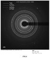
- FIG. 6 is a restricted field of view ED diagram of the low magnification final resultant product with a low magnification of 5, 000.
- FIG. 7 is a restricted field of view ED diagram of the high magnification final resultant product with a high magnification of 400, 000. According to an actual measurement value based on a diffraction pattern with a low magnification of 5,000 shown in FIG.
- metal compound particles of the final resultant product as a whole had a card house structure in which crystallites of Li 4 Ti 5 O 12 were stacked, and were titanium oxide particles in which the edge surface of the crystallites of Li 4 Ti 5 O 12 was transformed into Ti 4 O 7
- FIG. 8 is a differential pore volume distribution with a horizontal axis that represents a pore size and a vertical axis that represents an increment of a pore volume between measurement points.
- lithium titanate particles of Example 1 had a larger differential pore volume than lithium titanate particles of Comparative Example 1. It can be understood that, since a differential pore volume in such a range (100 nm) with a small pore size was large, an electrolytic solution entered the inside of lithium titanate particles, and an area of lithium titanate particles in contact with the electrolytic solution was large. In particular, a differential pore volume in a pore size range of 10 to 40 nm had a value of 0.01 cm 3 /g or more and additionally, a value of 0.02 cm 3 /g or more was obtained. Incidentally, when the diameter of the voids 3 in the TEM image in FIG. 3 was measured, the maximum diameter was about 500 nm. That is, it was confirmed that the voids 3 having a maximum diameter of about 500 nm and also fine voids indicated by a differential pore volume were included.
- Example 1-1 and Example 1-2 were obtained by changing a heat treatment temperature and a heat treatment time in the third process for manufacturing metal compound particles having a three-dimensional network structure.
- Example 1 100 g of the resultant product obtained by performing a heat treatment in a nitrogen atmosphere was heated at 500 °C for 6 hours in an oxygen atmosphere.
- Example 1-1 a negative electrode active material was obtained in the same manner as in Example 1 except that 100 g of the resultant product obtained by performing a heat treatment in a nitrogen atmosphere was heated at 350 °C for 3 hours.
- Example 1 100 g of the resultant product obtained by performing a heat treatment in a nitrogen atmosphere was heated at 500 °C for 6 hours in an oxygen atmosphere.
- Example 1-2 a negative electrode active material was obtained in the same manner as in Example 1 except that 100 g of the resultant product obtained by performing a heat treatment in a nitrogen atmosphere was heated at 300 °C for 1 hour.
- Example 1-1 and Example 1-2 Using the negative electrode active materials of Example 1-1 and Example 1-2, a hybrid capacitor was produced using the same conditions and the same method as in Example 1. The residual amounts of carbon of the obtained negative electrode active materials of Example 1, Example 1-1 and Example 1-2 were confirmed by TG-DTA measurement (differential thermal-thermogravimetric simultaneous measurement) . Here, a hybrid capacitor having a utilization ratio of 40% was used as a target for measuring the residual amount of carbon. Then, a storage test at 60 °C was performed for such examples. For storage test conditions, hybrid capacitors charged at 2.8 V were left for 30 minute, and were then left in an atmosphere at 60 °C for 1,500 hours. The discharging capacity when the capacitor was charged and discharged again was calculated as a fraction of the discharging capacity before the test. The results are shown in Table 2. (Table 2) Residual amount of carbon Storage test Example 1 1% or less 83% Example 1-1 3% 72% Example 1-2 5% 66%
- Example 2 when carbon in metal compound particles was burned and a three-dimensional network structure was created, carbon may remain in metal compound particles. In Example 1, 1 weight% or less of carbon remained. As shown in Table 1, the residual amount of carbon was preferably less than 5 weight%, and particularly, a favorable result was obtained in Example 1 in which the residual amount of carbon was 1 weight% or less.
- FIG. 9 is a graph showing the relationship between a utilization ratio of a negative electrode active material and an initial DCIR in Example 1 and a Comparative Example.
- lithium titanate particles of the related art were used as a negative electrode active material, and when the utilization ratio of the negative electrode active material increased, the direct current internal resistance increased accordingly, and increased sharply when the utilization ratio exceeded 45%.
- This example was prepared in the same manner as in Example 1 except that a positive electrode and a negative electrode were wound with a rayon separator therebetween and accommodated in an aluminum case with a bottomed cylindrical shape, and thus a wound type hybrid capacitor was produced, and hybrid capacitors having different utilization ratios such that a utilization ratio of a negative electrode active material was 10% to 80% in 10% increments were prepared.
- an aluminum case with an outer diameter of ⁇ 45 mm, and a height of 135 mm was used.
- FIG. 10 is a graph showing an initial DCIR and a discharging capacity with respect to a utilization ratio of the negative electrode active material of Example 1.
- the hybrid capacitor of Example 2 was the same as the hybrid capacitor of Example 1 in that an increase in the direct current internal resistance was reduced even if at least the utilization ratio increased, but the hybrid capacitor of Example 2 had a different relationship between a utilization ratio and a direct current internal resistance from the hybrid capacitor of Example 1. That is, it was confirmed that, in the hybrid capacitor of Example 2, when the utilization ratio increased in a range in which the utilization ratio was less than 40%, the direct current internal resistance significantly decreased. That is, an effect of significantly lowering a direct current internal resistance according to an increase in the utilization ratio was obtained. However, the numerical value itself of the direct current internal resistance was not the same as when the utilization ratio was 40% or more.
- Example 2 when Example 2 was of a wound type, if the negative electrode was made thicker in order to lower the utilization ratio of the negative electrode active material, there was an influence from the shortening of the current collector. That is, it is thought that, in lamination and sealing of Example 1, an accommodating volume was set according to the thickness of the negative electrode, but in Example 2, since the capacitor element was accommodated in a prescribed volume, the wound length was shorter according to the thickness of the negative electrode, the current collector was shortened, and the direct current internal resistance increased due to the current collector. This result showed that, even if the above point is considered, there was no change to the fact that, when at least the utilization ratio was in a range of 20% or more, even if the utilization ratio increased, an increase in the direct current internal resistance was reduced.
- the utilization ratio of the negative electrode active material is 20% or more and 80% or less, in other words, a discharging capacity of 100% of the negative electrode active material is 1.25 times or more and 5.0 times or less than a discharging capacity of 100% of the positive electrode active material.
- the utilization ratio of the negative electrode active material is 40% or more and 80% or less, in other words, a discharging capacity of 100% of the negative electrode active material is 1.25 times or more and 2.5 times or less than a discharging capacity of 100% of the positive electrode active material.
- a charging and discharging curve of the hybrid capacitor of Example 2 was checked.
- a potential of 1.0 V-2.5 V was maintained with respect to Li/Li + , and at room temperature, a charging and discharging current of 1.65 mA/mg (12C) flowed, and a charging and discharging capacity was measured.
- the test results are shown in FIG. 11 .
- a plateau region was 120 mAh/g with respect to a negative electrode capacity of 150 mAh/g.
- the utilization ratio of the negative electrode active material was desirably about 80%, in other words, a discharging capacity of 100% of the negative electrode active material was desirably 1.25 times a discharging capacity of 100% of the positive electrode active material.
Landscapes
- Engineering & Computer Science (AREA)
- Power Engineering (AREA)
- Microelectronics & Electronic Packaging (AREA)
- Chemical & Material Sciences (AREA)
- Materials Engineering (AREA)
- Manufacturing & Machinery (AREA)
- Electric Double-Layer Capacitors Or The Like (AREA)
- Battery Electrode And Active Subsutance (AREA)
Claims (4)
- Condensateur hybride comprenant :une électrode positive comprenant une couche d'un matériau actif à électrode positive ayant une capacitance à double couche électrique ; etune électrode négative ayant une couche de matériau actif à électrode négative comprenant des particules de composé métallique ayant une structure de réseau à trois dimensions (1) qui peut bloquer et libérer des ions lithium et dans laquelle des particules primaires (2) sont liées les unes aux autres par l'intermédiaire de vides (3),caractérisé en ce queles particules de composé métallique ont une structure de réseau à trois dimensions dans laquelle des cristallites de titanate de lithium sont reliés les uns aux autres ;dans lequel une phase de Magneli (2a) qui est un oxyde de titane représenté par une formule générale TinO2n-1 (3 ≤ n ≤ 10) est formée sur une partie des surfaces des cristallites ; etdans lequel, en mesurant une capacité de décharge de 100 % par unité de masse d'une couche de matériau actif à électrode négative et une capacité de décharge de 100 % par unité de masse d'une couche de matériau actif à électrode positive, les quantités de la couche de matériau actif à électrode positive et de la couche de matériau actif à électrode négative sont ajustées de telle sorte qu'une capacité de décharge de 100 % de la couche de matériau actif à électrode négative est supérieure ou égale à 1,25 fois et inférieure ou égale à 5,0 fois une capacité de décharge de 100 % de la couche de matériau actif à électrode positive.
- Condensateur hybride selon la revendication 1, dans lequel les particules de composé métallique (2) comprennent moins de 5 % en poids de carbone.
- Condensateur hybride selon la revendication 1 ou la revendication 2, dans lequel, dans un volume de pore différentiel (4) converti à partir d'une distribution de pore obtenue par l'analyse des particules de composé métallique (2) en utilisant un procédé de mesure d'adsorption de gaz d'azote, le volume de pore différentiel dans une plage de taille de pore comprise entre 10 et 40 nm a une valeur supérieure ou égale à 0,01 cm3/g.
- Procédé de fabrication d'un condensateur hybride, comprenant :un premier procédé dans lequel un précurseur de particules de composé métallique (2) et une source de carbone sont combinés pour obtenir un premier matériau composite ;un deuxième procédé dans lequel le premier matériau composite est chauffé sous une atmosphère non oxydante afin de générer des particules de composé métallique, et les particules de composé métallique et le carbone sont combinés pour obtenir un deuxième matériau composite ;un troisième procédé dans lequel le deuxième matériau composite est chauffé sous une atmosphère d'oxygène pour obtenir les particules de composé métallique à partir desquelles le carbone est éliminé ;un quatrième procédé de préparation d'une électrode négative utilisant les particules de composé métallique à partir desquelles le carbone est éliminé obtenues lors du troisième procédé en tant que matériau actif à électrode négative ; etun cinquième procédé de formation d'un élément imprégné d'une solution électrolytique dans laquelle une électrode positive et l'électrode négative obtenue lors du quatrième procédé se font face avec un séparateur entre celles-ci,dans lequel les particules de composé métallique ont la structure de réseau à trois dimensions (1) dans laquelle des cristallites de titanate de lithium sont reliés les uns aux autres ;dans lequel une phase de Magneli (2a) qui est un oxyde de titane représenté par une formule générale TinO2n-1 (3 ≤ n ≤ 10) est formée sur une partie des surfaces des cristallites ; etdans lequel, dans le cinquième procédé, une capacité de décharge de 100 % par unité de masse d'une couche de matériau actif à électrode négative et une capacité de décharge de 100 % par unité de masse d'une couche de matériau actif à électrode positive sont mesurées, et les quantités de la couche de matériau actif à électrode positive et de la couche de matériau actif à électrode négative sont ajustées de telle sorte qu'une capacité de décharge de 100 % de la couche de matériau actif à électrode négative est supérieure ou égale à 1,25 fois et inférieure ou égale à 5,0 fois une capacité de décharge de 100 % de la couche de matériau actif à électrode positive.
Applications Claiming Priority (2)
| Application Number | Priority Date | Filing Date | Title |
|---|---|---|---|
| JP2016124015A JP6834187B2 (ja) | 2016-06-22 | 2016-06-22 | ハイブリッドキャパシタ及びその製造方法 |
| PCT/JP2017/022320 WO2017221831A1 (fr) | 2016-06-22 | 2017-06-16 | Condensateur hybride et procédé de fabrication de celui-ci |
Publications (3)
| Publication Number | Publication Date |
|---|---|
| EP3477671A1 EP3477671A1 (fr) | 2019-05-01 |
| EP3477671A4 EP3477671A4 (fr) | 2020-03-04 |
| EP3477671B1 true EP3477671B1 (fr) | 2022-01-19 |
Family
ID=60784733
Family Applications (1)
| Application Number | Title | Priority Date | Filing Date |
|---|---|---|---|
| EP17815299.7A Active EP3477671B1 (fr) | 2016-06-22 | 2017-06-16 | Condensateur hybride et procédé de fabrication de celui-ci |
Country Status (6)
| Country | Link |
|---|---|
| US (1) | US10984961B2 (fr) |
| EP (1) | EP3477671B1 (fr) |
| JP (1) | JP6834187B2 (fr) |
| KR (1) | KR102323183B1 (fr) |
| CN (1) | CN109313991B (fr) |
| WO (1) | WO2017221831A1 (fr) |
Families Citing this family (3)
| Publication number | Priority date | Publication date | Assignee | Title |
|---|---|---|---|---|
| JP6743513B2 (ja) * | 2016-06-22 | 2020-08-19 | 日本ケミコン株式会社 | ハイブリッドキャパシタ及びその製造方法 |
| WO2020105603A1 (fr) * | 2018-11-22 | 2020-05-28 | 日本ケミコン株式会社 | Groupe de particules de composé métallique, électrode pour dispositif de stockage d'énergie, dispositif de stockage d'énergie et méthode de production d'un groupe de particules de composé métallique |
| CN113597690A (zh) | 2019-03-29 | 2021-11-02 | 旭化成株式会社 | 非水系碱金属蓄电元件的制造方法 |
Family Cites Families (16)
| Publication number | Priority date | Publication date | Assignee | Title |
|---|---|---|---|---|
| CA2327370A1 (fr) * | 2000-12-05 | 2002-06-05 | Hydro-Quebec | Nouvelle methode de fabrication de li4ti5o12 pur a partir du compose ternaire tix-liy-carbone: effet du carbone sur la synthese et la conductivite de l'electrode |
| JP2002270175A (ja) | 2001-03-09 | 2002-09-20 | Asahi Glass Co Ltd | 二次電源 |
| JP4099970B2 (ja) | 2001-10-24 | 2008-06-11 | 旭硝子株式会社 | 二次電源 |
| JP2007018883A (ja) | 2005-07-07 | 2007-01-25 | Toshiba Corp | 負極活物質、非水電解質電池及び電池パック |
| JP5836568B2 (ja) | 2010-05-04 | 2015-12-24 | 日本ケミコン株式会社 | チタン酸リチウム結晶構造体とカーボンの複合体、その製造方法、その複合体を用いた電極及び電気化学素子 |
| JP5672859B2 (ja) | 2010-08-26 | 2015-02-18 | 宇部興産株式会社 | 微細な炭素繊維と複合化されたリチウムチタン複合酸化物電極材料 |
| WO2012169331A1 (fr) * | 2011-06-10 | 2012-12-13 | 東邦チタニウム株式会社 | Particules primaires de titanate de lithium, agrégat de titanate de lithium, batterie secondaire au lithium-ion mettant en oeuvre les particules primaires de titanate de lithium ou l'agrégat de titanate de lithium et condensateur au lithium-ion mettant en oeuvre les particules primaires de titanate de lithium ou l'agrégat de titanate de lithium |
| JP5757173B2 (ja) * | 2011-06-17 | 2015-07-29 | アイシン精機株式会社 | 蓄電デバイス |
| CN102496704B (zh) * | 2011-12-08 | 2014-04-23 | 中信国安盟固利电源技术有限公司 | 一种钛酸锂/亚氧化钛负极材料及其制备方法 |
| JPWO2014007188A1 (ja) * | 2012-07-04 | 2016-06-02 | 住友電気工業株式会社 | リチウムイオンキャパシタ |
| JP2014086164A (ja) * | 2012-10-19 | 2014-05-12 | Jgc Catalysts & Chemicals Ltd | リチウムイオン二次電池用負極材、該負極材の製造方法ならびに該負極材を用いた二次電池 |
| JP2014130719A (ja) | 2012-12-28 | 2014-07-10 | Ricoh Co Ltd | 非水電解液蓄電素子 |
| JP2014183161A (ja) * | 2013-03-19 | 2014-09-29 | Sumitomo Electric Ind Ltd | リチウムイオンキャパシタおよびその充放電方法 |
| JP6138554B2 (ja) * | 2013-04-03 | 2017-05-31 | 日本ケミコン株式会社 | 複合材料、この複合材料の製造方法、この複合材料を用いたリチウムイオン二次電池及び電気化学キャパシタ |
| KR101479626B1 (ko) * | 2013-05-03 | 2015-01-06 | 삼화콘덴서공업주식회사 | Lto/탄소 복합체, lto/탄소 복합체 제조방법, lto/탄소 복합체를 이용한 이용한 음극활물질 및 음극활물질을 이용한 하이브리드 슈퍼커패시터 |
| CN105580098B (zh) | 2013-08-19 | 2019-06-21 | 日本贵弥功株式会社 | 电化学电容器 |
-
2016
- 2016-06-22 JP JP2016124015A patent/JP6834187B2/ja active Active
-
2017
- 2017-06-16 WO PCT/JP2017/022320 patent/WO2017221831A1/fr not_active Ceased
- 2017-06-16 CN CN201780037902.4A patent/CN109313991B/zh active Active
- 2017-06-16 KR KR1020187032280A patent/KR102323183B1/ko active Active
- 2017-06-16 EP EP17815299.7A patent/EP3477671B1/fr active Active
-
2018
- 2018-12-20 US US16/228,687 patent/US10984961B2/en active Active
Also Published As
| Publication number | Publication date |
|---|---|
| CN109313991A (zh) | 2019-02-05 |
| KR102323183B1 (ko) | 2021-11-09 |
| EP3477671A4 (fr) | 2020-03-04 |
| JP2017228665A (ja) | 2017-12-28 |
| US10984961B2 (en) | 2021-04-20 |
| CN109313991B (zh) | 2021-09-21 |
| KR20190019050A (ko) | 2019-02-26 |
| US20190131079A1 (en) | 2019-05-02 |
| WO2017221831A1 (fr) | 2017-12-28 |
| EP3477671A1 (fr) | 2019-05-01 |
| JP6834187B2 (ja) | 2021-02-24 |
Similar Documents
| Publication | Publication Date | Title |
|---|---|---|
| US12199268B2 (en) | Non-aqueous lithium power storage element | |
| KR101396521B1 (ko) | 리튬 이차 전지용 음극 활물질, 이의 제조 방법, 그리고 이를 포함하는 음극 및 리튬 이차 전지 | |
| KR101137375B1 (ko) | 2차 입자 및 이를 구비한 리튬 전지 | |
| JP7042589B2 (ja) | 負極 | |
| US8865102B2 (en) | Carbon material and method for producing same | |
| US20230343937A1 (en) | Silicon-carbon composite particle, negative electrode active material, and negative electrode, electrochemical apparatus, and electronic apparatus containing same | |
| JP6675146B2 (ja) | 非水系リチウム型蓄電素子 | |
| EP4235720A1 (fr) | Élément de stockage d'énergie en métal alcalin non aqueux et liquide de revêtement d'électrode positive | |
| JP2014139942A (ja) | リチウムイオン二次電池用炭素被覆黒鉛負極材、その製造方法、該負極材を用いたリチウムイオン二次電池用負極及びリチウムイオン二次電池 | |
| JP2017228439A (ja) | リチウムイオン二次電池及びその製造方法 | |
| US10984961B2 (en) | Hybrid capacitor and manufacturing method thereof | |
| EP3477670B1 (fr) | Condensateur hybride et procédé de fabrication de celui-ci | |
| JP5707707B2 (ja) | リチウムイオン二次電池用負極材、該負極材を用いたリチウムイオン二次電池用負極及びリチウムイオン二次電池 | |
| JP5590159B2 (ja) | リチウムイオン二次電池用負極材、その製造方法、該負極材を用いたリチウムイオン二次電池用負極およびリチウムイオン二次電池 | |
| JP6754657B2 (ja) | 非水系リチウム型蓄電素子 | |
| JP2017228438A (ja) | リチウム二次電池及びその製造方法 | |
| JP2026067096A (ja) | リチウムイオン二次電池の製造方法及びリチウムイオン二次電池 | |
| JP2018056431A (ja) | 非水系リチウム型蓄電素子 | |
| WO2026095055A1 (fr) | Matériau actif d'électrode négative, procédé pour produire un matériau actif d'électrode négative, et batterie | |
| EP4685881A1 (fr) | Matériau de carbone de graphite pour anode de batterie secondaire au lithium-ion, matériau d'anode pour batterie secondaire au lithium-ion, anode pour batterie secondaire au lithium-ion, et batterie secondaire au lithium-ion | |
| JP2023024002A (ja) | 正極前駆体及びその製造方法 | |
| JP2018056440A (ja) | 非水系リチウム型蓄電素子 |
Legal Events
| Date | Code | Title | Description |
|---|---|---|---|
| STAA | Information on the status of an ep patent application or granted ep patent |
Free format text: STATUS: THE INTERNATIONAL PUBLICATION HAS BEEN MADE |
|
| PUAI | Public reference made under article 153(3) epc to a published international application that has entered the european phase |
Free format text: ORIGINAL CODE: 0009012 |
|
| STAA | Information on the status of an ep patent application or granted ep patent |
Free format text: STATUS: REQUEST FOR EXAMINATION WAS MADE |
|
| 17P | Request for examination filed |
Effective date: 20181218 |
|
| AK | Designated contracting states |
Kind code of ref document: A1 Designated state(s): AL AT BE BG CH CY CZ DE DK EE ES FI FR GB GR HR HU IE IS IT LI LT LU LV MC MK MT NL NO PL PT RO RS SE SI SK SM TR |
|
| AX | Request for extension of the european patent |
Extension state: BA ME |
|
| DAV | Request for validation of the european patent (deleted) | ||
| DAX | Request for extension of the european patent (deleted) | ||
| REG | Reference to a national code |
Ref country code: DE Ref legal event code: R079 Ref document number: 602017052554 Country of ref document: DE Free format text: PREVIOUS MAIN CLASS: H01G0011500000 Ipc: H01G0011460000 |
|
| A4 | Supplementary search report drawn up and despatched |
Effective date: 20200131 |
|
| RIC1 | Information provided on ipc code assigned before grant |
Ipc: H01G 11/24 20130101ALI20200127BHEP Ipc: H01M 4/485 20100101ALI20200127BHEP Ipc: H01G 11/86 20130101ALI20200127BHEP Ipc: H01G 11/46 20130101AFI20200127BHEP Ipc: H01G 11/60 20130101ALI20200127BHEP Ipc: H01G 11/62 20130101ALI20200127BHEP Ipc: H01G 11/06 20130101ALI20200127BHEP Ipc: H01G 11/50 20130101ALI20200127BHEP Ipc: H01G 11/84 20130101ALI20200127BHEP |
|
| GRAP | Despatch of communication of intention to grant a patent |
Free format text: ORIGINAL CODE: EPIDOSNIGR1 |
|
| STAA | Information on the status of an ep patent application or granted ep patent |
Free format text: STATUS: GRANT OF PATENT IS INTENDED |
|
| INTG | Intention to grant announced |
Effective date: 20210928 |
|
| GRAS | Grant fee paid |
Free format text: ORIGINAL CODE: EPIDOSNIGR3 |
|
| GRAA | (expected) grant |
Free format text: ORIGINAL CODE: 0009210 |
|
| STAA | Information on the status of an ep patent application or granted ep patent |
Free format text: STATUS: THE PATENT HAS BEEN GRANTED |
|
| AK | Designated contracting states |
Kind code of ref document: B1 Designated state(s): AL AT BE BG CH CY CZ DE DK EE ES FI FR GB GR HR HU IE IS IT LI LT LU LV MC MK MT NL NO PL PT RO RS SE SI SK SM TR |
|
| REG | Reference to a national code |
Ref country code: GB Ref legal event code: FG4D |
|
| REG | Reference to a national code |
Ref country code: CH Ref legal event code: EP |
|
| REG | Reference to a national code |
Ref country code: DE Ref legal event code: R096 Ref document number: 602017052554 Country of ref document: DE |
|
| REG | Reference to a national code |
Ref country code: AT Ref legal event code: REF Ref document number: 1464275 Country of ref document: AT Kind code of ref document: T Effective date: 20220215 |
|
| REG | Reference to a national code |
Ref country code: IE Ref legal event code: FG4D |
|
| REG | Reference to a national code |
Ref country code: LT Ref legal event code: MG9D |
|
| REG | Reference to a national code |
Ref country code: NL Ref legal event code: MP Effective date: 20220119 |
|
| REG | Reference to a national code |
Ref country code: AT Ref legal event code: MK05 Ref document number: 1464275 Country of ref document: AT Kind code of ref document: T Effective date: 20220119 |
|
| PG25 | Lapsed in a contracting state [announced via postgrant information from national office to epo] |
Ref country code: NL Free format text: LAPSE BECAUSE OF FAILURE TO SUBMIT A TRANSLATION OF THE DESCRIPTION OR TO PAY THE FEE WITHIN THE PRESCRIBED TIME-LIMIT Effective date: 20220119 |
|
| PG25 | Lapsed in a contracting state [announced via postgrant information from national office to epo] |
Ref country code: SE Free format text: LAPSE BECAUSE OF FAILURE TO SUBMIT A TRANSLATION OF THE DESCRIPTION OR TO PAY THE FEE WITHIN THE PRESCRIBED TIME-LIMIT Effective date: 20220119 Ref country code: RS Free format text: LAPSE BECAUSE OF FAILURE TO SUBMIT A TRANSLATION OF THE DESCRIPTION OR TO PAY THE FEE WITHIN THE PRESCRIBED TIME-LIMIT Effective date: 20220119 Ref country code: PT Free format text: LAPSE BECAUSE OF FAILURE TO SUBMIT A TRANSLATION OF THE DESCRIPTION OR TO PAY THE FEE WITHIN THE PRESCRIBED TIME-LIMIT Effective date: 20220519 Ref country code: NO Free format text: LAPSE BECAUSE OF FAILURE TO SUBMIT A TRANSLATION OF THE DESCRIPTION OR TO PAY THE FEE WITHIN THE PRESCRIBED TIME-LIMIT Effective date: 20220419 Ref country code: LT Free format text: LAPSE BECAUSE OF FAILURE TO SUBMIT A TRANSLATION OF THE DESCRIPTION OR TO PAY THE FEE WITHIN THE PRESCRIBED TIME-LIMIT Effective date: 20220119 Ref country code: HR Free format text: LAPSE BECAUSE OF FAILURE TO SUBMIT A TRANSLATION OF THE DESCRIPTION OR TO PAY THE FEE WITHIN THE PRESCRIBED TIME-LIMIT Effective date: 20220119 Ref country code: ES Free format text: LAPSE BECAUSE OF FAILURE TO SUBMIT A TRANSLATION OF THE DESCRIPTION OR TO PAY THE FEE WITHIN THE PRESCRIBED TIME-LIMIT Effective date: 20220119 Ref country code: BG Free format text: LAPSE BECAUSE OF FAILURE TO SUBMIT A TRANSLATION OF THE DESCRIPTION OR TO PAY THE FEE WITHIN THE PRESCRIBED TIME-LIMIT Effective date: 20220419 |
|
| PG25 | Lapsed in a contracting state [announced via postgrant information from national office to epo] |
Ref country code: PL Free format text: LAPSE BECAUSE OF FAILURE TO SUBMIT A TRANSLATION OF THE DESCRIPTION OR TO PAY THE FEE WITHIN THE PRESCRIBED TIME-LIMIT Effective date: 20220119 Ref country code: LV Free format text: LAPSE BECAUSE OF FAILURE TO SUBMIT A TRANSLATION OF THE DESCRIPTION OR TO PAY THE FEE WITHIN THE PRESCRIBED TIME-LIMIT Effective date: 20220119 Ref country code: GR Free format text: LAPSE BECAUSE OF FAILURE TO SUBMIT A TRANSLATION OF THE DESCRIPTION OR TO PAY THE FEE WITHIN THE PRESCRIBED TIME-LIMIT Effective date: 20220420 Ref country code: FI Free format text: LAPSE BECAUSE OF FAILURE TO SUBMIT A TRANSLATION OF THE DESCRIPTION OR TO PAY THE FEE WITHIN THE PRESCRIBED TIME-LIMIT Effective date: 20220119 Ref country code: AT Free format text: LAPSE BECAUSE OF FAILURE TO SUBMIT A TRANSLATION OF THE DESCRIPTION OR TO PAY THE FEE WITHIN THE PRESCRIBED TIME-LIMIT Effective date: 20220119 |
|
| PG25 | Lapsed in a contracting state [announced via postgrant information from national office to epo] |
Ref country code: IS Free format text: LAPSE BECAUSE OF FAILURE TO SUBMIT A TRANSLATION OF THE DESCRIPTION OR TO PAY THE FEE WITHIN THE PRESCRIBED TIME-LIMIT Effective date: 20220519 |
|
| REG | Reference to a national code |
Ref country code: DE Ref legal event code: R097 Ref document number: 602017052554 Country of ref document: DE |
|
| PG25 | Lapsed in a contracting state [announced via postgrant information from national office to epo] |
Ref country code: SM Free format text: LAPSE BECAUSE OF FAILURE TO SUBMIT A TRANSLATION OF THE DESCRIPTION OR TO PAY THE FEE WITHIN THE PRESCRIBED TIME-LIMIT Effective date: 20220119 Ref country code: SK Free format text: LAPSE BECAUSE OF FAILURE TO SUBMIT A TRANSLATION OF THE DESCRIPTION OR TO PAY THE FEE WITHIN THE PRESCRIBED TIME-LIMIT Effective date: 20220119 Ref country code: RO Free format text: LAPSE BECAUSE OF FAILURE TO SUBMIT A TRANSLATION OF THE DESCRIPTION OR TO PAY THE FEE WITHIN THE PRESCRIBED TIME-LIMIT Effective date: 20220119 Ref country code: EE Free format text: LAPSE BECAUSE OF FAILURE TO SUBMIT A TRANSLATION OF THE DESCRIPTION OR TO PAY THE FEE WITHIN THE PRESCRIBED TIME-LIMIT Effective date: 20220119 Ref country code: DK Free format text: LAPSE BECAUSE OF FAILURE TO SUBMIT A TRANSLATION OF THE DESCRIPTION OR TO PAY THE FEE WITHIN THE PRESCRIBED TIME-LIMIT Effective date: 20220119 Ref country code: CZ Free format text: LAPSE BECAUSE OF FAILURE TO SUBMIT A TRANSLATION OF THE DESCRIPTION OR TO PAY THE FEE WITHIN THE PRESCRIBED TIME-LIMIT Effective date: 20220119 |
|
| PLBE | No opposition filed within time limit |
Free format text: ORIGINAL CODE: 0009261 |
|
| STAA | Information on the status of an ep patent application or granted ep patent |
Free format text: STATUS: NO OPPOSITION FILED WITHIN TIME LIMIT |
|
| PG25 | Lapsed in a contracting state [announced via postgrant information from national office to epo] |
Ref country code: AL Free format text: LAPSE BECAUSE OF FAILURE TO SUBMIT A TRANSLATION OF THE DESCRIPTION OR TO PAY THE FEE WITHIN THE PRESCRIBED TIME-LIMIT Effective date: 20220119 |
|
| 26N | No opposition filed |
Effective date: 20221020 |
|
| PG25 | Lapsed in a contracting state [announced via postgrant information from national office to epo] |
Ref country code: MC Free format text: LAPSE BECAUSE OF FAILURE TO SUBMIT A TRANSLATION OF THE DESCRIPTION OR TO PAY THE FEE WITHIN THE PRESCRIBED TIME-LIMIT Effective date: 20220119 |
|
| REG | Reference to a national code |
Ref country code: CH Ref legal event code: PL |
|
| REG | Reference to a national code |
Ref country code: BE Ref legal event code: MM Effective date: 20220630 |
|
| PG25 | Lapsed in a contracting state [announced via postgrant information from national office to epo] |
Ref country code: SI Free format text: LAPSE BECAUSE OF FAILURE TO SUBMIT A TRANSLATION OF THE DESCRIPTION OR TO PAY THE FEE WITHIN THE PRESCRIBED TIME-LIMIT Effective date: 20220119 |
|
| GBPC | Gb: european patent ceased through non-payment of renewal fee |
Effective date: 20220616 |
|
| PG25 | Lapsed in a contracting state [announced via postgrant information from national office to epo] |
Ref country code: LU Free format text: LAPSE BECAUSE OF NON-PAYMENT OF DUE FEES Effective date: 20220616 Ref country code: LI Free format text: LAPSE BECAUSE OF NON-PAYMENT OF DUE FEES Effective date: 20220630 Ref country code: IE Free format text: LAPSE BECAUSE OF NON-PAYMENT OF DUE FEES Effective date: 20220616 Ref country code: FR Free format text: LAPSE BECAUSE OF NON-PAYMENT OF DUE FEES Effective date: 20220630 Ref country code: CH Free format text: LAPSE BECAUSE OF NON-PAYMENT OF DUE FEES Effective date: 20220630 |
|
| PG25 | Lapsed in a contracting state [announced via postgrant information from national office to epo] |
Ref country code: GB Free format text: LAPSE BECAUSE OF NON-PAYMENT OF DUE FEES Effective date: 20220616 Ref country code: BE Free format text: LAPSE BECAUSE OF NON-PAYMENT OF DUE FEES Effective date: 20220630 |
|
| PG25 | Lapsed in a contracting state [announced via postgrant information from national office to epo] |
Ref country code: IT Free format text: LAPSE BECAUSE OF FAILURE TO SUBMIT A TRANSLATION OF THE DESCRIPTION OR TO PAY THE FEE WITHIN THE PRESCRIBED TIME-LIMIT Effective date: 20220119 |
|
| P01 | Opt-out of the competence of the unified patent court (upc) registered |
Effective date: 20230731 |
|
| PG25 | Lapsed in a contracting state [announced via postgrant information from national office to epo] |
Ref country code: HU Free format text: LAPSE BECAUSE OF FAILURE TO SUBMIT A TRANSLATION OF THE DESCRIPTION OR TO PAY THE FEE WITHIN THE PRESCRIBED TIME-LIMIT; INVALID AB INITIO Effective date: 20170616 |
|
| PG25 | Lapsed in a contracting state [announced via postgrant information from national office to epo] |
Ref country code: MK Free format text: LAPSE BECAUSE OF FAILURE TO SUBMIT A TRANSLATION OF THE DESCRIPTION OR TO PAY THE FEE WITHIN THE PRESCRIBED TIME-LIMIT Effective date: 20220119 Ref country code: CY Free format text: LAPSE BECAUSE OF FAILURE TO SUBMIT A TRANSLATION OF THE DESCRIPTION OR TO PAY THE FEE WITHIN THE PRESCRIBED TIME-LIMIT Effective date: 20220119 |
|
| PG25 | Lapsed in a contracting state [announced via postgrant information from national office to epo] |
Ref country code: TR Free format text: LAPSE BECAUSE OF FAILURE TO SUBMIT A TRANSLATION OF THE DESCRIPTION OR TO PAY THE FEE WITHIN THE PRESCRIBED TIME-LIMIT Effective date: 20220119 |
|
| PG25 | Lapsed in a contracting state [announced via postgrant information from national office to epo] |
Ref country code: MT Free format text: LAPSE BECAUSE OF FAILURE TO SUBMIT A TRANSLATION OF THE DESCRIPTION OR TO PAY THE FEE WITHIN THE PRESCRIBED TIME-LIMIT Effective date: 20220119 |
|
| PGFP | Annual fee paid to national office [announced via postgrant information from national office to epo] |
Ref country code: DE Payment date: 20250618 Year of fee payment: 9 |