EP3477679B1 - Verbesserte kryogene zelle zum anbringen einer probe in einem geladenen teilchenmikroskop - Google Patents
Verbesserte kryogene zelle zum anbringen einer probe in einem geladenen teilchenmikroskop Download PDFInfo
- Publication number
- EP3477679B1 EP3477679B1 EP17198436.2A EP17198436A EP3477679B1 EP 3477679 B1 EP3477679 B1 EP 3477679B1 EP 17198436 A EP17198436 A EP 17198436A EP 3477679 B1 EP3477679 B1 EP 3477679B1
- Authority
- EP
- European Patent Office
- Prior art keywords
- specimen
- cryogenic
- cell
- tube
- charged particle
- Prior art date
- Legal status (The legal status is an assumption and is not a legal conclusion. Google has not performed a legal analysis and makes no representation as to the accuracy of the status listed.)
- Active
Links
Images
Classifications
-
- H—ELECTRICITY
- H01—ELECTRIC ELEMENTS
- H01J—ELECTRIC DISCHARGE TUBES OR DISCHARGE LAMPS
- H01J37/00—Discharge tubes with provision for introducing objects or material to be exposed to the discharge, e.g. for the purpose of examination or processing thereof
- H01J37/02—Details
- H01J37/20—Means for supporting or positioning the object or the material; Means for adjusting diaphragms or lenses associated with the support
-
- H—ELECTRICITY
- H01—ELECTRIC ELEMENTS
- H01J—ELECTRIC DISCHARGE TUBES OR DISCHARGE LAMPS
- H01J37/00—Discharge tubes with provision for introducing objects or material to be exposed to the discharge, e.g. for the purpose of examination or processing thereof
- H01J37/26—Electron or ion microscopes; Electron or ion diffraction tubes
-
- H—ELECTRICITY
- H01—ELECTRIC ELEMENTS
- H01J—ELECTRIC DISCHARGE TUBES OR DISCHARGE LAMPS
- H01J2237/00—Discharge tubes exposing object to beam, e.g. for analysis treatment, etching, imaging
- H01J2237/20—Positioning, supporting, modifying or maintaining the physical state of objects being observed or treated
- H01J2237/2001—Maintaining constant desired temperature
-
- H—ELECTRICITY
- H01—ELECTRIC ELEMENTS
- H01J—ELECTRIC DISCHARGE TUBES OR DISCHARGE LAMPS
- H01J2237/00—Discharge tubes exposing object to beam, e.g. for analysis treatment, etching, imaging
- H01J2237/20—Positioning, supporting, modifying or maintaining the physical state of objects being observed or treated
- H01J2237/2002—Controlling environment of sample
Definitions
- the tube is thermally clamped into a cooperating cavity in the cell, by virtue of a difference in thermal coefficient of expansion between said extremity/cavity; in such a structure, the tube and cavity can be easily separated at room temperature, but become tightly clamped together when cooled, for example.
- Complementary material pairs for this latter embodiment include, for example, aluminum / titanium.
- An elongate tube as used in the present invention can, for example, be manufactured by conventional machining techniques, such as drilling a longitudinal bore along the cylindrical axis of a solid metallic cylinder, for example.
- machining techniques such as drilling a longitudinal bore along the cylindrical axis of a solid metallic cylinder, for example.
- Yet another alternative would be to cast the tube using an annular-cylindrical mold into which liquid metal is poured. The skilled artisan will be able to select a manufacturing technique that is suited to the needs of a given situation.
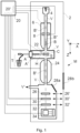
- Figure 1 (not to scale) is a highly schematic depiction of an embodiment of a CPM M in which the present invention is implemented; more specifically, it shows an embodiment of a TEM/STEM (though, in the context of the current invention, it could just as validly be an ion-based microscope or a SEM, for example).
- a vacuum enclosure V which can be evacuated by a schematically depicted vacuum pump assembly V'.
- spectroscopic apparatus 34 can also be integrated into the imaging system 24.
- controller 20 is connected to various illustrated components via control lines (buses) 20'.
- This controller 20 can provide a variety of functions, such as synchronizing actions, providing setpoints, processing signals, performing calculations, and displaying messages/information on a display device (not depicted).
- the (schematically depicted) controller 20 may be (partially) inside or outside the cabinet 2, and may have a unitary or composite structure, as desired.
- the interior of the enclosure V does not have to be kept at a strict vacuum; for example, in a so-called "Environmental TEM/STEM", a background atmosphere of a given gas is deliberately introduced / maintained within the enclosure V.
- both apertures 10, 12 are disposed (e.g. centered) upon beam axis B', and can have a diameter of ca. 1 mm, for example.
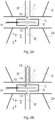
- the tube 14 can have a height (parallel to Z) of ca. 60mm, and an internal diameter (in the XY plane) of ca. 1mm - though other values are, of course, possible.
- the tube 14 may, if desired, be demountable/detachable from the cryogenic cell C; alternatively, it can be permanently attached to the cell C, e.g . using a solder joint, or adhesive connection, for instance.
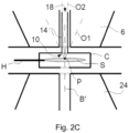
- FIG 2C this schematically illustrates an effect of the invention as applied in Figure 2B relative to the prior-art situation of Figure 2A .
- the coarse broken line O1 delimits an acceptance angle of aperture 10 relative to an intersection point p of beam axis B' with specimen S; essentially, this line O1 skims the edges of aperture 10, and defines the surface of an associated acceptance cone.
- the fine broken line O2 delimits an acceptance angle of aperture 18 relative to said point p, and defines the surface of an associated acceptance cone. It is immediately evident that the (conical) acceptable angle / opening angle associated with line O2 (present invention) is much smaller than that associated with line O1 (prior art).
Landscapes
- Chemical & Material Sciences (AREA)
- Analytical Chemistry (AREA)
- Analysing Materials By The Use Of Radiation (AREA)
Claims (5)
- Verfahren zum Untersuchen eines kryogenen Objekts (S) in einem Ladungsteilchenmikroskop, umfassend:- Bereitstellen des Objekts (S) in einer kryogenen Zelle (C) auf einem Objekthalter (H);- Lenken eines Ladungsteilchenstrahls von einer Quelle und entlang einer Achse (B') über einen evakuierten Strahlkanal (B") eines Beleuchtungssystems, um mindestens einen Abschnitt des Objekts damit zu bestrahlen;- Verwenden eines Detektors (30, 32, 34), um Strahlung zu detektieren, die von dem Objekt (S) als Reaktion auf die Bestrahlung ausgeht,- Konfigurieren der Zelle, um eine längliche Röhre (14) zu umfassen, die sich innerhalb des Strahlenkanals in das Beleuchtungssystem erstreckt und die Achse umschließt;- Halten der Röhre auf einer kryogenen Temperatur mindestens während der Bestrahlung,wobei:- der Objekthalter unter Verwendung einer Temperaturregelanordnung (T) auf einer kryogenen Temperatur gehalten wird;- die längliche Röhre thermisch leitende Wände aufweist, die sich mit der kryogenen Zelle eng verbinden, wobei infolgedessen die Röhre auf eine kryogene Temperatur gekühlt wird;
dadurch gekennzeichnet, dass- die kryogene Zelle aufgrund eines engen thermischen Kontakts mit dem Objekthalter auf einer kryogenen Temperatur gehalten wird. - Verfahren nach Anspruch 1, wobei die längliche Röhre (14) konfiguriert ist, um von der Zelle abnehmbar zu sein.
- Verfahren nach Anspruch 2, wobei ein Ende der Röhre (14), aufgrund eines Unterschieds in einem thermischen Ausdehnungskoeffizienten zwischen dem Ende und dem Hohlraum, in einen zusammenwirkenden Hohlraum in der Zelle thermisch eingeklemmt wird.
- Verfahren nach einem der Ansprüche 1 bis 3, wobei die längliche Röhre (14) als eine Kühlfalle eingesetzt wird, um Wassermoleküle einzufangen und gefrieren zu lassen, die auf ihre Innenwände auftreffen.
- Ladungsteilchenmikroskop, umfassend:- eine kryogene Zelle (C), in der ein Objekt (S) bereitgestellt werden kann, und einen Objekthalter (H) zum Festhalten der kryogenen Zelle;- eine Ladungsteilchenquelle zum Erzeugen eines Ladungsteilchenstrahls;- ein Beleuchtungssystem zum Lenken des Strahls entlang einer Achse (B') über einen evakuierbaren Strahlkanal (B"), um mindestens einen Abschnitt des Objekts mit dem Strahl zu bestrahlen:- einen Detektor (30, 32, 34) zum Detektieren von Strahlung, die als Reaktion auf die Bestrahlung von dem Objekt ausgeht, wobei- die Zelle eine längliche Röhre (14) umfasst, die sich innerhalb des Strahlenkanals in das Beleuchtungssystem erstreckt und die Achse umschließt;- die Röhre mit einer Kühlungsvorrichtung zum Halten dieser auf einer kryogenen Temperatur mindestens während der Bestrahlung verbindbar ist, wobei:- der Objekthalter unter Verwendung einer Temperaturregelanordnung (T) auf einer kryogenen Temperatur gehalten wird;- die längliche Röhre thermisch leitende Wände aufweist, die sich mit der kryogenen Zelle eng verbinden, wobei infolgedessen die Röhre auf eine kryogene Temperatur gekühlt wird,
dadurch gekennzeichnet, dass- die kryogene Zelle, in Verwendung, aufgrund des engen thermischen Kontakts mit dem Objekthalter auf einer kryogenen Temperatur gehalten wird.
Priority Applications (2)
| Application Number | Priority Date | Filing Date | Title |
|---|---|---|---|
| EP17198436.2A EP3477679B1 (de) | 2017-10-26 | 2017-10-26 | Verbesserte kryogene zelle zum anbringen einer probe in einem geladenen teilchenmikroskop |
| US16/166,242 US10651007B2 (en) | 2017-10-26 | 2018-10-22 | Cryogenic cell for mounting a specimen in a charged particle microscope |
Applications Claiming Priority (1)
| Application Number | Priority Date | Filing Date | Title |
|---|---|---|---|
| EP17198436.2A EP3477679B1 (de) | 2017-10-26 | 2017-10-26 | Verbesserte kryogene zelle zum anbringen einer probe in einem geladenen teilchenmikroskop |
Publications (2)
| Publication Number | Publication Date |
|---|---|
| EP3477679A1 EP3477679A1 (de) | 2019-05-01 |
| EP3477679B1 true EP3477679B1 (de) | 2025-01-08 |
Family
ID=60186115
Family Applications (1)
| Application Number | Title | Priority Date | Filing Date |
|---|---|---|---|
| EP17198436.2A Active EP3477679B1 (de) | 2017-10-26 | 2017-10-26 | Verbesserte kryogene zelle zum anbringen einer probe in einem geladenen teilchenmikroskop |
Country Status (2)
| Country | Link |
|---|---|
| US (1) | US10651007B2 (de) |
| EP (1) | EP3477679B1 (de) |
Families Citing this family (1)
| Publication number | Priority date | Publication date | Assignee | Title |
|---|---|---|---|---|
| US12123816B2 (en) * | 2021-06-21 | 2024-10-22 | Fei Company | Vibration-free cryogenic cooling |
Family Cites Families (9)
| Publication number | Priority date | Publication date | Assignee | Title |
|---|---|---|---|---|
| US3171957A (en) * | 1962-03-30 | 1965-03-02 | Rca Corp | Specimen holder for an electron microscope with means to support a specimen across a thermocouple junction |
| JPS5748274Y2 (de) * | 1977-07-11 | 1982-10-22 | ||
| DE3374490D1 (en) * | 1982-04-20 | 1987-12-17 | Univ Glasgow | Low temperature stage for microanalysis |
| JP2000260378A (ja) * | 1999-03-08 | 2000-09-22 | Hitachi Ltd | 電子線装置 |
| DE10344492B4 (de) * | 2003-09-24 | 2006-09-07 | Carl Zeiss Nts Gmbh | Teilchenstrahlgerät |
| EP1852888A1 (de) * | 2006-05-01 | 2007-11-07 | FEI Company | Teilchenoptischer Apparat mit Temperaturschalter |
| EP2853847B1 (de) | 2013-09-30 | 2016-02-03 | Fei Company | Herstellung einer kryogenen Probe für Ladungsteilchenmikroskopie |
| EP3062082B1 (de) | 2015-02-25 | 2018-04-18 | Fei Company | Herstellung einer Probe für Ladungsteilchenmikroskop |
| EP3486633B1 (de) | 2015-12-11 | 2021-11-24 | FEI Company | Vorbereitung der kryogenen probe für die ladungsteilchenmikroskopie |
-
2017
- 2017-10-26 EP EP17198436.2A patent/EP3477679B1/de active Active
-
2018
- 2018-10-22 US US16/166,242 patent/US10651007B2/en active Active
Also Published As
| Publication number | Publication date |
|---|---|
| US10651007B2 (en) | 2020-05-12 |
| EP3477679A1 (de) | 2019-05-01 |
| US20190131105A1 (en) | 2019-05-02 |
Similar Documents
| Publication | Publication Date | Title |
|---|---|---|
| US11004655B2 (en) | Diffraction pattern detection in a transmission charged particle microscope | |
| JP7145776B2 (ja) | 走査透過荷電粒子顕微鏡におけるインテリジェントプレスキャン | |
| US20230207254A1 (en) | Electron microscope with improved imaging resolution | |
| US10157727B2 (en) | Aberration measurement in a charged particle microscope | |
| US10453647B2 (en) | Emission noise correction of a charged particle source | |
| US20180151329A1 (en) | Time-of-flight charged particle spectroscopy | |
| US11417498B2 (en) | Method of manufacturing a charged particle detector | |
| JP7278983B2 (ja) | マルチビーム走査透過荷電粒子顕微鏡 | |
| JP2017212194A (ja) | 現位置堆積機能を備える荷電粒子顕微鏡 | |
| EP3399537B1 (de) | Kanonenlinsendesign in einem ladungsträgerteilchenmikroskop | |
| US20180061613A1 (en) | Charged-particle microscope with exchangeable pole piece extending element | |
| EP3401943B1 (de) | Innovative bildverarbeitung in der ladungsteilchenmikroskopie | |
| EP3489989B1 (de) | Ladungsträgerteilchenmikroskop mit einstellbarer strahlenergiespreizung | |
| US10651007B2 (en) | Cryogenic cell for mounting a specimen in a charged particle microscope | |
| US10559448B2 (en) | Transmission charged particle microscope with improved EELS/EFTEM module |
Legal Events
| Date | Code | Title | Description |
|---|---|---|---|
| PUAI | Public reference made under article 153(3) epc to a published international application that has entered the european phase |
Free format text: ORIGINAL CODE: 0009012 |
|
| STAA | Information on the status of an ep patent application or granted ep patent |
Free format text: STATUS: THE APPLICATION HAS BEEN PUBLISHED |
|
| AK | Designated contracting states |
Kind code of ref document: A1 Designated state(s): AL AT BE BG CH CY CZ DE DK EE ES FI FR GB GR HR HU IE IS IT LI LT LU LV MC MK MT NL NO PL PT RO RS SE SI SK SM TR |
|
| AX | Request for extension of the european patent |
Extension state: BA ME |
|
| STAA | Information on the status of an ep patent application or granted ep patent |
Free format text: STATUS: REQUEST FOR EXAMINATION WAS MADE |
|
| 17P | Request for examination filed |
Effective date: 20191023 |
|
| RBV | Designated contracting states (corrected) |
Designated state(s): AL AT BE BG CH CY CZ DE DK EE ES FI FR GB GR HR HU IE IS IT LI LT LU LV MC MK MT NL NO PL PT RO RS SE SI SK SM TR |
|
| STAA | Information on the status of an ep patent application or granted ep patent |
Free format text: STATUS: EXAMINATION IS IN PROGRESS |
|
| 17Q | First examination report despatched |
Effective date: 20211014 |
|
| GRAP | Despatch of communication of intention to grant a patent |
Free format text: ORIGINAL CODE: EPIDOSNIGR1 |
|
| STAA | Information on the status of an ep patent application or granted ep patent |
Free format text: STATUS: GRANT OF PATENT IS INTENDED |
|
| INTG | Intention to grant announced |
Effective date: 20240802 |
|
| GRAS | Grant fee paid |
Free format text: ORIGINAL CODE: EPIDOSNIGR3 |
|
| GRAA | (expected) grant |
Free format text: ORIGINAL CODE: 0009210 |
|
| STAA | Information on the status of an ep patent application or granted ep patent |
Free format text: STATUS: THE PATENT HAS BEEN GRANTED |
|
| AK | Designated contracting states |
Kind code of ref document: B1 Designated state(s): AL AT BE BG CH CY CZ DE DK EE ES FI FR GB GR HR HU IE IS IT LI LT LU LV MC MK MT NL NO PL PT RO RS SE SI SK SM TR |
|
| REG | Reference to a national code |
Ref country code: GB Ref legal event code: FG4D |
|
| REG | Reference to a national code |
Ref country code: CH Ref legal event code: EP |
|
| REG | Reference to a national code |
Ref country code: DE Ref legal event code: R096 Ref document number: 602017087218 Country of ref document: DE |
|
| REG | Reference to a national code |
Ref country code: IE Ref legal event code: FG4D |
|
| P01 | Opt-out of the competence of the unified patent court (upc) registered |
Free format text: CASE NUMBER: APP_13595/2025 Effective date: 20250319 |
|
| REG | Reference to a national code |
Ref country code: LT Ref legal event code: MG9D |
|
| REG | Reference to a national code |
Ref country code: NL Ref legal event code: MP Effective date: 20250108 |
|
| REG | Reference to a national code |
Ref country code: AT Ref legal event code: MK05 Ref document number: 1758908 Country of ref document: AT Kind code of ref document: T Effective date: 20250108 |
|
| PG25 | Lapsed in a contracting state [announced via postgrant information from national office to epo] |
Ref country code: NL Free format text: LAPSE BECAUSE OF FAILURE TO SUBMIT A TRANSLATION OF THE DESCRIPTION OR TO PAY THE FEE WITHIN THE PRESCRIBED TIME-LIMIT Effective date: 20250108 |
|
| PG25 | Lapsed in a contracting state [announced via postgrant information from national office to epo] |
Ref country code: RS Free format text: LAPSE BECAUSE OF FAILURE TO SUBMIT A TRANSLATION OF THE DESCRIPTION OR TO PAY THE FEE WITHIN THE PRESCRIBED TIME-LIMIT Effective date: 20250408 |
|
| PG25 | Lapsed in a contracting state [announced via postgrant information from national office to epo] |
Ref country code: FI Free format text: LAPSE BECAUSE OF FAILURE TO SUBMIT A TRANSLATION OF THE DESCRIPTION OR TO PAY THE FEE WITHIN THE PRESCRIBED TIME-LIMIT Effective date: 20250108 |
|
| PG25 | Lapsed in a contracting state [announced via postgrant information from national office to epo] |
Ref country code: PL Free format text: LAPSE BECAUSE OF FAILURE TO SUBMIT A TRANSLATION OF THE DESCRIPTION OR TO PAY THE FEE WITHIN THE PRESCRIBED TIME-LIMIT Effective date: 20250108 |
|
| PG25 | Lapsed in a contracting state [announced via postgrant information from national office to epo] |
Ref country code: ES Free format text: LAPSE BECAUSE OF FAILURE TO SUBMIT A TRANSLATION OF THE DESCRIPTION OR TO PAY THE FEE WITHIN THE PRESCRIBED TIME-LIMIT Effective date: 20250108 |
|
| PG25 | Lapsed in a contracting state [announced via postgrant information from national office to epo] |
Ref country code: IS Free format text: LAPSE BECAUSE OF FAILURE TO SUBMIT A TRANSLATION OF THE DESCRIPTION OR TO PAY THE FEE WITHIN THE PRESCRIBED TIME-LIMIT Effective date: 20250508 Ref country code: NO Free format text: LAPSE BECAUSE OF FAILURE TO SUBMIT A TRANSLATION OF THE DESCRIPTION OR TO PAY THE FEE WITHIN THE PRESCRIBED TIME-LIMIT Effective date: 20250408 |
|
| PG25 | Lapsed in a contracting state [announced via postgrant information from national office to epo] |
Ref country code: HR Free format text: LAPSE BECAUSE OF FAILURE TO SUBMIT A TRANSLATION OF THE DESCRIPTION OR TO PAY THE FEE WITHIN THE PRESCRIBED TIME-LIMIT Effective date: 20250108 |
|
| PG25 | Lapsed in a contracting state [announced via postgrant information from national office to epo] |
Ref country code: LV Free format text: LAPSE BECAUSE OF FAILURE TO SUBMIT A TRANSLATION OF THE DESCRIPTION OR TO PAY THE FEE WITHIN THE PRESCRIBED TIME-LIMIT Effective date: 20250108 Ref country code: PT Free format text: LAPSE BECAUSE OF FAILURE TO SUBMIT A TRANSLATION OF THE DESCRIPTION OR TO PAY THE FEE WITHIN THE PRESCRIBED TIME-LIMIT Effective date: 20250508 |
|
| PG25 | Lapsed in a contracting state [announced via postgrant information from national office to epo] |
Ref country code: GR Free format text: LAPSE BECAUSE OF FAILURE TO SUBMIT A TRANSLATION OF THE DESCRIPTION OR TO PAY THE FEE WITHIN THE PRESCRIBED TIME-LIMIT Effective date: 20250409 Ref country code: BG Free format text: LAPSE BECAUSE OF FAILURE TO SUBMIT A TRANSLATION OF THE DESCRIPTION OR TO PAY THE FEE WITHIN THE PRESCRIBED TIME-LIMIT Effective date: 20250108 |
|
| PG25 | Lapsed in a contracting state [announced via postgrant information from national office to epo] |
Ref country code: AT Free format text: LAPSE BECAUSE OF FAILURE TO SUBMIT A TRANSLATION OF THE DESCRIPTION OR TO PAY THE FEE WITHIN THE PRESCRIBED TIME-LIMIT Effective date: 20250108 |
|
| PG25 | Lapsed in a contracting state [announced via postgrant information from national office to epo] |
Ref country code: SE Free format text: LAPSE BECAUSE OF FAILURE TO SUBMIT A TRANSLATION OF THE DESCRIPTION OR TO PAY THE FEE WITHIN THE PRESCRIBED TIME-LIMIT Effective date: 20250108 |
|
| PG25 | Lapsed in a contracting state [announced via postgrant information from national office to epo] |
Ref country code: SM Free format text: LAPSE BECAUSE OF FAILURE TO SUBMIT A TRANSLATION OF THE DESCRIPTION OR TO PAY THE FEE WITHIN THE PRESCRIBED TIME-LIMIT Effective date: 20250108 |
|
| REG | Reference to a national code |
Ref country code: DE Ref legal event code: R097 Ref document number: 602017087218 Country of ref document: DE |
|
| PG25 | Lapsed in a contracting state [announced via postgrant information from national office to epo] |
Ref country code: DK Free format text: LAPSE BECAUSE OF FAILURE TO SUBMIT A TRANSLATION OF THE DESCRIPTION OR TO PAY THE FEE WITHIN THE PRESCRIBED TIME-LIMIT Effective date: 20250108 |
|
| PG25 | Lapsed in a contracting state [announced via postgrant information from national office to epo] |
Ref country code: CZ Free format text: LAPSE BECAUSE OF FAILURE TO SUBMIT A TRANSLATION OF THE DESCRIPTION OR TO PAY THE FEE WITHIN THE PRESCRIBED TIME-LIMIT Effective date: 20250108 Ref country code: EE Free format text: LAPSE BECAUSE OF FAILURE TO SUBMIT A TRANSLATION OF THE DESCRIPTION OR TO PAY THE FEE WITHIN THE PRESCRIBED TIME-LIMIT Effective date: 20250108 |
|
| PG25 | Lapsed in a contracting state [announced via postgrant information from national office to epo] |
Ref country code: RO Free format text: LAPSE BECAUSE OF FAILURE TO SUBMIT A TRANSLATION OF THE DESCRIPTION OR TO PAY THE FEE WITHIN THE PRESCRIBED TIME-LIMIT Effective date: 20250108 |
|
| PG25 | Lapsed in a contracting state [announced via postgrant information from national office to epo] |
Ref country code: SK Free format text: LAPSE BECAUSE OF FAILURE TO SUBMIT A TRANSLATION OF THE DESCRIPTION OR TO PAY THE FEE WITHIN THE PRESCRIBED TIME-LIMIT Effective date: 20250108 |
|
| PLBE | No opposition filed within time limit |
Free format text: ORIGINAL CODE: 0009261 |
|
| STAA | Information on the status of an ep patent application or granted ep patent |
Free format text: STATUS: NO OPPOSITION FILED WITHIN TIME LIMIT |
|
| 26N | No opposition filed |
Effective date: 20251009 |
|
| PGFP | Annual fee paid to national office [announced via postgrant information from national office to epo] |
Ref country code: DE Payment date: 20250919 Year of fee payment: 9 |
|
| PG25 | Lapsed in a contracting state [announced via postgrant information from national office to epo] |
Ref country code: IT Free format text: LAPSE BECAUSE OF FAILURE TO SUBMIT A TRANSLATION OF THE DESCRIPTION OR TO PAY THE FEE WITHIN THE PRESCRIBED TIME-LIMIT Effective date: 20250108 |