EP3477771B1 - Gedruckte dipolantenne, gruppenantenne und kommunikationsvorrichtung - Google Patents
Gedruckte dipolantenne, gruppenantenne und kommunikationsvorrichtung Download PDFInfo
- Publication number
- EP3477771B1 EP3477771B1 EP18202719.3A EP18202719A EP3477771B1 EP 3477771 B1 EP3477771 B1 EP 3477771B1 EP 18202719 A EP18202719 A EP 18202719A EP 3477771 B1 EP3477771 B1 EP 3477771B1
- Authority
- EP
- European Patent Office
- Prior art keywords
- feed line
- printed dipole
- segment
- antenna
- printed
- Prior art date
- Legal status (The legal status is an assumption and is not a legal conclusion. Google has not performed a legal analysis and makes no representation as to the accuracy of the status listed.)
- Active
Links
Images




Classifications
-
- H—ELECTRICITY
- H01—ELECTRIC ELEMENTS
- H01Q—ANTENNAS, i.e. RADIO AERIALS
- H01Q21/00—Antenna arrays or systems
- H01Q21/06—Arrays of individually energised antenna units similarly polarised and spaced apart
- H01Q21/061—Two dimensional planar arrays
- H01Q21/062—Two dimensional planar arrays using dipole aerials
-
- H—ELECTRICITY
- H01—ELECTRIC ELEMENTS
- H01Q—ANTENNAS, i.e. RADIO AERIALS
- H01Q1/00—Details of, or arrangements associated with, antennas
- H01Q1/36—Structural form of radiating elements, e.g. cone, spiral, umbrella; Particular materials used therewith
- H01Q1/38—Structural form of radiating elements, e.g. cone, spiral, umbrella; Particular materials used therewith formed by a conductive layer on an insulating support
-
- H—ELECTRICITY
- H01—ELECTRIC ELEMENTS
- H01Q—ANTENNAS, i.e. RADIO AERIALS
- H01Q21/00—Antenna arrays or systems
- H01Q21/0006—Particular feeding systems
-
- H—ELECTRICITY
- H01—ELECTRIC ELEMENTS
- H01Q—ANTENNAS, i.e. RADIO AERIALS
- H01Q21/00—Antenna arrays or systems
- H01Q21/0006—Particular feeding systems
- H01Q21/0025—Modular arrays
-
- H—ELECTRICITY
- H01—ELECTRIC ELEMENTS
- H01Q—ANTENNAS, i.e. RADIO AERIALS
- H01Q21/00—Antenna arrays or systems
- H01Q21/0087—Apparatus or processes specially adapted for manufacturing antenna arrays
-
- H—ELECTRICITY
- H01—ELECTRIC ELEMENTS
- H01Q—ANTENNAS, i.e. RADIO AERIALS
- H01Q21/00—Antenna arrays or systems
- H01Q21/06—Arrays of individually energised antenna units similarly polarised and spaced apart
- H01Q21/08—Arrays of individually energised antenna units similarly polarised and spaced apart the units being spaced along or adjacent to a rectilinear path
- H01Q21/12—Parallel arrangements of substantially straight elongated conductive units
-
- H—ELECTRICITY
- H01—ELECTRIC ELEMENTS
- H01Q—ANTENNAS, i.e. RADIO AERIALS
- H01Q5/00—Arrangements for simultaneous operation of antennas on two or more different wavebands, e.g. dual-band or multi-band arrangements
- H01Q5/30—Arrangements for providing operation on different wavebands
- H01Q5/307—Individual or coupled radiating elements, each element being fed in an unspecified way
- H01Q5/342—Individual or coupled radiating elements, each element being fed in an unspecified way for different propagation modes
- H01Q5/35—Individual or coupled radiating elements, each element being fed in an unspecified way for different propagation modes using two or more simultaneously fed points
-
- H—ELECTRICITY
- H01—ELECTRIC ELEMENTS
- H01Q—ANTENNAS, i.e. RADIO AERIALS
- H01Q9/00—Electrically-short antennas having dimensions not more than twice the operating wavelength and consisting of conductive active radiating elements
- H01Q9/04—Resonant antennas
- H01Q9/06—Details
- H01Q9/065—Microstrip dipole antennas
Definitions
- This disclosure relates to the field of wireless communications technologies, and in particular, to a printed dipole antenna, an array antenna, and a communications device.
- a wireless local area network is widely applied to a home, an office, and another indoor/outdoor environment.
- WLAN wireless local area network
- a high-density deployment scenario for example, a stadium, where a height of an antenna above a ground is approximately 15 m to 50 m
- a small-angle directional antenna needs to be used to reduce a coverage radius of a single access point device.
- a sidelobe suppression capability of the directional antenna determines a capability to suppress co-channel interference between adjacent access point devices in the high-density deployment scenario.
- US 6,831,602 relates to low cost trombone line beamformer.
- US 6,285,323 relates to flat plate antenna arrays.
- US 8,200,168 relates to programmable antenna assembly and applications thereof.
- This disclosure is intended to reduce co-channel interference between adjacent access point devices in a high-density deployment scenario.
- the feed lines parallel to the printed dipoles each include different segments, and each segment approaches a printed dipole on one side of the segment, to suppress parasitic emission of the feed lines, and implement a low sidelobe level of the printed dipole antenna.
- the low sidelobe level of the printed dipole antenna is implemented within a 5GHz frequency band by setting the lengths of the first segment, the second segment, the third segment, and the fourth segment of the feed lines and the related distances.
- printed dipoles of adjacent printed dipole antennas of the array antenna are perpendicular to each other, reducing parasitic emission between the adjacent printed dipole antennas, and implementing a low sidelobe level of the array antenna.
- the feed lines parallel to the printed dipoles of the printed dipole antennas each include different segments, and each segment approaches a printed dipole antenna on one side of the segment, to suppress parasitic emission of the feed lines between the printed dipole antennas, and implement a low sidelobe level of the array antenna.
- printed dipoles of adjacent printed dipole antennas of the array antenna are perpendicular to each other, reducing parasitic emission between the adjacent printed dipole antennas, and implementing a low sidelobe level of the array antenna.
- FIG. 1 shows a printed dipole antenna according to an aspect of the present disclosure.
- the printed dipole antenna includes a first printed dipole 101, a second printed dipole 102, a third printed dipole 103, a fourth printed dipole 104, a first feed line 201, a second feed line 202, a third feed line 203, and a fourth feed line 204.
- Two arms of any one of the first printed dipole 101, the second printed dipole 102, the third printed dipole 103, and the fourth printed dipole 104 are disposed on an upper surface and a lower surface of a dielectric substrate respectively, and extend towards opposite directions.
- any one of the first feed line 201, the second feed line 202, the third feed line 203, and the fourth feed line 204 is disposed on the upper surface and the lower surface of the dielectric substrate.
- the first printed dipole 101 is parallel to the second printed dipole 102, and is perpendicular to the first feed line 201.
- the first printed dipole 101 is connected to one end of the first feed line 201, and the second printed dipole 102 is connected to the other end of the first feed line 201.
- the third printed dipole 103 is parallel to the fourth printed dipole 104, and is perpendicular to the second feed line 202.
- the third printed dipole 103 is connected to one end of the second feed line 202, and the fourth printed dipole 104 is connected to the other end of the second feed line 202.
- One end of the third feed line 203 is connected to the first feed line 201, and a connection point between the third feed line 203 and the first feed line 201 is any point on the first feed line 201 different from the two ends of the first feed line 201.
- the other end of the third feed line 203 is connected to one end of the fourth feed line 204, the other end of the fourth feed line 204 is connected to the second feed line 202, and a connection point between the fourth feed line 204 and the second feed line 202 is any point on the second feed line 202 different from the two ends of the second feed line 202.
- the third feed line 203 includes a first segment 2031 and a second segment 2032
- the fourth feed line 204 includes a third segment 2041 and a fourth segment 2042.
- the first segment 2031 is parallel to the first printed dipole 101, and a distance from the first segment 2031 to the first printed dipole 101 is less than a distance from a midpoint of the first feed line 201 to the first printed dipole 101.
- the second segment 2032 is parallel to the second printed dipole 102, and a distance from the second segment 2032 to the second printed dipole 102 is less than a distance from the midpoint of the first feed line 201 to the second printed dipole 102.
- the third segment 2041 is parallel to the third printed dipole 103, and a distance from the third segment 2041 to the third printed dipole 103 is less than a distance from a midpoint of the second feed line 202 to the third printed dipole 103.
- the fourth segment 2042 is parallel to the fourth printed dipole 104, and a distance from the fourth segment 2042 to the fourth printed dipole 104 is less than a distance from the midpoint of the second feed line 202 to the fourth printed dipole 104.
- the feed lines parallel to the printed dipoles each include different segments, and each segment approaches a printed dipole on one side of the segment, to suppress parasitic emission of the feed lines, and implement a low sidelobe level of the printed dipole antenna.
- a distance from the first segment 2031 to the midpoint of the first feed line 201 is 0.2 to 0.6 times a guided wavelength.
- a distance from the second segment 2032 to the midpoint of the first feed line 201 is 0.2 to 0.6 times the guided wavelength.
- a distance from the third segment 2041 to the midpoint of the second feed line 202 is 0.2 to 0.6 times the guided wavelength.
- a distance from the fourth segment 2042 to the midpoint of the second feed line 202 is 0.2 to 0.6 times the guided wavelength.
- a length of the first segment 2031 is 0.1 to 0.3 times the guided wavelength.
- Alength of the second segment 2032 is 0.1 to 0.3 times the guided wavelength.
- a length of the third segment 2041 is 0.1 to 0.3 times the guided wavelength.
- a length of the fourth segment 2042 is 0.1 to 0.3 times the guided wavelength.
- the feed line is a double-sided parallel-strip line, and therefore the feed line is a waveguide.
- the guided wavelength is a wavelength of electromagnetic wave travelling along an axis of guided wave in the waveguide, that is, a guided wavelength of the feed line.
- the low sidelobe level of the printed dipole antenna is implemented within a 5GHz frequency band by setting the lengths of the first segment 2031, the second segment 2032, the third segment 2041, and the fourth segment 2042 of the feed lines and the related distances.
- One end of the first segment 2031 is connected to the first feed line by using two feed lines, and the two feed lines include a feed line parallel to the first feed line 201 and a feed line perpendicular to the first feed line 201.
- the other end of the first segment 2031 is connected to one end of the second segment 2032 by using a feed line parallel to the first feed line 201, and the other end of the second segment 2032 is connected to the fourth feed line 204.
- One end of the third segment 2041 is connected to the second feed line 202 by using two feed lines, and the two feed lines include one feed line parallel to the second feed line 202 and one feed line perpendicular to the second feed line 202.
- the other end of the third segment 2041 is connected to one end of the fourth segment 2042 by using a feed line parallel to the second feed line 202, and the other end of the fourth segment 2042 is connected to the third feed line 203.
- the feed lines parallel to the printed dipoles are optimized. If the optimized feed line design is applied to an array antenna, a plurality of the printed dipole antennas provided in this aspect of the present disclosure may be used to form an array antenna.
- FIG. 2 is a schematic structural diagram of an array antenna according to Aspect 1 of the present disclosure.
- the array antenna includes four printed dipole antennas, and printed dipoles of any two adjacent printed dipole antennas of the four printed dipole antennas are perpendicular to each other.
- Printed dipoles of adjacent printed dipole antennas of the array antenna are perpendicular to each other, reducing parasitic emission between the adjacent printed dipole antennas, and implementing a low sidelobe level of the array antenna.
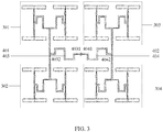
- FIG. 3 is a schematic structural diagram of an array antenna according to Aspect 2 of the present disclosure.
- the array antenna includes a first printed dipole antenna 301, a second printed dipole antenna 302, a third printed dipole antenna 303, a fourth printed dipole antenna 304, a fifth feed line 401, a sixth feed line 402, a seventh feed line 403, and an eighth feed line 404, and all printed dipoles of the four printed dipole antennas are parallel.
- a printed dipole of the first printed dipole antenna 301 is parallel to a printed dipole of the second printed dipole antenna 302, and is perpendicular to the fifth feed line 401.
- the first printed dipole antenna 301 is connected to one end of the fifth feed line 401, and the second printed dipole antenna 302 is connected to the other end of the fifth feed line 401.
- a printed dipole of the third printed dipole antenna 303 is parallel to a printed dipole of the fourth printed dipole antenna 304, and is perpendicular to the sixth feed line 402.
- the third printed dipole antenna 303 is connected to one end of the sixth feed line 402, and the fourth printed dipole antenna 304 is connected to the other end of the sixth feed line 402.
- One end of the seventh feed line 403 is connected to the fifth feed line 401, and a connection point between the seventh feed line 403 and the fifth feed line 401 is any point on the fifth feed line 401 different from the two ends of the fifth feed line 401.
- the other end of the seventh feed line 403 is connected to one end of the eighth feed line 404, the other end of the eighth feed line 404 is connected to the sixth feed line 402, and a connection point between the eighth feed line 404 and the sixth feed line 402 is any point on the sixth feed line 402 different from the two ends of the sixth feed line 402.
- the seventh feed line 403 includes a fifth segment 4031 and a sixth segment 4032
- the eighth feed line 404 includes a seventh segment 4041 and an eighth segment 4042.
- One end of the fifth segment 4031 is connected to the fifth feed line 401 by using two feed lines, and the two feed lines include one feed line parallel to the fifth feed line 401 and one feed line perpendicular to the fifth feed line 401.
- the other end of the fifth segment 4031 is connected to one end of the sixth segment 4032 by using a feed line parallel to the fifth feed line 401, and the other end of the sixth segment 4032 is connected to the eighth feed line 404.
- One end of the seventh segment 4041 is connected to the sixth feed line 402 by using two feed lines, and the two feed lines include one feed line parallel to the sixth feed line 402 and one feed line perpendicular to the sixth feed line 402.
- the other end of the seventh segment 4041 is connected to one end of the eighth segment 4042 by using a feed line parallel to the sixth feed line 402, and the other end of the eighth segment 4042 is connected to the seventh feed line 403.
- the fifth segment 4031 is parallel to the printed dipole of the first printed dipole antenna 301, and a distance from the fifth segment 4031 to the printed dipole of the first printed dipole antenna 301 is less than a distance from a midpoint of the fifth feed line 401 to the printed dipole of the first printed dipole antenna 301.
- the sixth segment 4032 is parallel to the printed dipole of the second printed dipole antenna 302, and a distance from the sixth segment 4032 to the printed dipole of the second printed dipole antenna 302 is less than a distance from the midpoint of the fifth feed line 401 to the printed dipole of the second printed dipole antenna 302.
- the seventh segment 4041 is parallel to the printed dipole of the third printed dipole antenna 303, and a distance from the seventh segment 4041 to the printed dipole of the third printed dipole antenna 303 is less than a distance from a midpoint of the sixth feed line 402 to the printed dipole of the third printed dipole antenna 303.
- the eighth segment 4042 is parallel to the printed dipole of the fourth printed dipole antenna 304, and a distance from the eighth segment 4042 to the printed dipole of the fourth printed dipole antenna 304 is less than a distance from the midpoint of the sixth feed line 402 to the printed dipole of the fourth printed dipole antenna 304.
- the feed lines parallel to the printed dipoles of the printed dipole antennas each include different segments, and each segment approaches a printed dipole antenna on one side of the segment, to suppress parasitic emission of the feed lines between the printed dipole antennas, and implement a low sidelobe level of the array antenna.
- FIG. 4 is a schematic structural diagram of an array antenna according to Aspect 3 of the present disclosure.
- the array antenna includes four array antennas shown in FIG. 3 .
- Printed dipoles of any two adjacent array antennas of the four array antennas shown in FIG. 3 are perpendicular to each other.
- Printed dipoles of adjacent printed dipole antennas of the array antenna are perpendicular to each other, reducing parasitic emission between the adjacent printed dipole antennas, and implementing a low sidelobe level of the array antenna.
- FIG. 5 is a schematic structural diagram of a 4x4 array antenna.
- FIG. 6 is a simulation schematic diagram of radiation of the array antenna shown in FIG. 5 . It can be seen that a test result of the array antenna shown in FIG. 5 is that a sidelobe level is less than -9 decibel (dB).
- FIG. 7 is a schematic structural diagram of a 4x4 array antenna obtained after feed lines parallel to printed dipole antennas of the array antenna shown in FIG. 5 are shielded. For example, a reflection panel may be used to isolate the feed lines parallel to printed dipoles.
- FIG. 8 is a simulation schematic diagram of radiation of the array antenna shown in FIG. 7 . It can be seen that a test result of the array antenna shown in FIG.
- FIG. 7 is that a sidelobe level is less than - 21 dB.
- FIG. 9 is a schematic structural diagram of a printed dipole antenna according to an aspect of the present disclosure.
- FIG. 10 is a simulation schematic diagram of radiation of the array antenna shown in FIG. 9 . It can be seen that a test result of the printed dipole antenna using the structure in this aspect of the present disclosure is that a sidelobe level is less than - 19 dB. Based on comparison between the test results, the array antenna provided in this disclosure reduces parasitic emission of feed lines and between printed dipole antennas, and a low sidelobe level of the array antenna can be implemented.
- FIG. 11 is a schematic diagram of test data of a 2x2 array antenna according to an aspect of the present disclosure.
- lines represent data line graphs generated at different frequencies in a frequency band ranging from 5150 megahertz (MHz) to 5850 MHz.
- a test result of a test performed on the 2x2 array antenna provided in this aspect of the present disclosure is that a sidelobe level is less than -18 dB.
- FIG. 12 is a schematic diagram of test data of a 4x4 array antenna according to an aspect of the present disclosure.
- lines represent data line graphs generated at different frequencies in a frequency band ranging from 5150 MHz to 5850 MHz.
- a test result of a test performed on the 4x4 array antenna provided in this aspect of the present disclosure is that a sidelobe level is less than -16 dB. Because of a measurement error in sidelobe measurement by a measuring system and a processing error, FIG. 12 is not completely the same as the simulation diagram shown in FIG. 10 .
- FIG. 13 shows a communications device according to an aspect of the present disclosure.
- the communications device is a wireless access point (AP) or a communications device that radiates/receives a signal by using an array antenna.
- the communications device includes a radio frequency circuit 1301 and an antenna 1302.
- the antenna 1302 is a printed dipole antenna or an array antenna, and the radio frequency circuit 1301 is configured to radiate and/or receive a signal by using the antenna 1302.
- a quantity of array elements is not limited in the array antenna provided in the aspects of the present disclosure.
- the test proves that according to the array antenna provided in this disclosure, a low-sidelobe-level design of a 2x2 or 4x4 array antenna can be implemented. An average sidelobe level in an array pattern is less than -16 dB. This proves that the array antenna provided in this disclosure can suppress a level of the parasitic radiation generated by the printed dipole antennas and the feed lines to be less than the sidelobe level of-16 dB.
Landscapes
- Engineering & Computer Science (AREA)
- Manufacturing & Machinery (AREA)
- Variable-Direction Aerials And Aerial Arrays (AREA)
- Details Of Aerials (AREA)
Claims (8)
- Gruppenantenne, wobei die Gruppenantenne ein dielektrisches Substrat und eine Vielzahl von gedruckten Dipolantennen umfasst und jede gedruckte Dipolantenne einen ersten gedruckten Dipol (101), einen zweiten gedruckten Dipol (102), einen dritten gedruckten Dipol (103), einen vierten gedruckten Dipol (104), eine erste Speiseleitung (201), eine zweite Speiseleitung (202), eine dritte Speiseleitung (203), eine vierte Speiseleitung (204) umfasst, wobei
zwei Arme des ersten gedruckten Dipols (101), des zweiten gedruckten Dipols (102), des dritten gedruckten Dipols (103) und des vierten gedruckten Dipols (104) jeweils auf einer oberen Fläche und einer unteren Fläche des dielektrischen Substrats angeordnet sind und sich in entgegengesetzten Richtungen erstrecken;
jede Speiseleitung eine doppelseitige Parallelstreifenleitung ist, sodass jede Speiseleitung ein Wellenleiter ist, eine geführte Wellenlänge eine Wellenlänge einer elektromagnetischen Welle ist, die sich entlang der Speiseleitung im dielektrischen Substrat ausbreitet;
der erste gedruckte Dipol (101) parallel zum zweiten gedruckten Dipol (102) ist und rechtwinklig zur ersten Speiseleitung (201) ist; der erste gedruckte Dipol (101) mit einem Ende der ersten Speiseleitung (201) verbunden ist und der zweite gedruckte Dipol (102) mit dem anderen Ende der ersten Speiseleitung (201) verbunden ist;
der dritte gedruckte Dipol (103) parallel zum vierten gedruckten Dipol (104) ist und rechtwinklig zur zweiten Speiseleitung (202) ist; der dritte gedruckte Dipol (103) mit einem Ende der zweiten Speiseleitung (202) verbunden ist und der vierte gedruckte Dipol (104) mit dem anderen Ende der zweiten Speiseleitung (202) verbunden ist; ein Ende der dritten Speiseleitung (203) mit der ersten Speiseleitung (201) verbunden ist, das andere Ende der dritten Speiseleitung (203) mit einem Ende der vierten Speiseleitung (204) verbunden ist und das andere Ende der vierten Speiseleitung (204) mit der zweiten Speiseleitung (202) verbunden ist; und
die dritte Speiseleitung (203) ein erstes Segment (2031) und ein zweites Segment (2032) umfasst,
und die vierte Speiseleitung (204) ein drittes Segment (2041) und ein viertes Segment (2042) umfasst, wobei
das erste Segment (2031) parallel zum ersten gedruckten Dipol (101) ist und ein Abstand vom ersten Segment (2031) zum ersten gedruckten Dipol (101) kleiner als ein Abstand von einem Mittelpunkt der ersten Speiseleitung (201) zum ersten gedruckten Dipol (101) ist; das zweite Segment (2032) parallel zum zweiten gedruckten Dipol (102) ist und ein Abstand vom zweiten Segment (2032) zum zweiten gedruckten Dipol (102) kleiner als ein Abstand vom Mittelpunkt der ersten Speiseleitung (201) zum zweiten gedruckten Dipol (102) ist; und
das dritte Segment (2041) parallel zum dritten gedruckten Dipol (103) ist und ein Abstand vom dritten Segment (2041) zum dritten gedruckten Dipol (103) kleiner als ein Abstand von einem Mittelpunkt der zweiten Speiseleitung (202) zum dritten gedruckten Dipol (103) ist; das vierte Segment (2042) parallel zum vierten gedruckten Dipol (104) ist und ein Abstand vom vierten Segment (2042) zum vierten gedruckten Dipol (104) kleiner als ein Abstand vom Mittelpunkt der zweiten Speiseleitung (202) zum vierten gedruckten Dipol (104) ist;
wobei ein Abstand vom ersten Segment (2031) zum Mittelpunkt der ersten Speiseleitung (201) das 0,2- bis 0,6-fache der geführten Wellenlänge beträgt; ein Abstand vom zweiten Segment (2032) zum Mittelpunkt der ersten Speiseleitung (201) das 0,2- bis 0,6-fache der geführten Wellenlänge beträgt; ein Abstand vom dritten Segment (2041) zum Mittelpunkt der zweiten Speiseleitung (202) das 0,2- bis 0,6-fache der geführten Wellenlänge beträgt; und ein Abstand vom vierten Segment (2042) zum Mittelpunkt der zweiten Speiseleitung (202) das 0,2- bis 0,6-fache der geführten Wellenlänge ist. - Gruppenantenne gemäß Anspruch 1, wobei eine Länge des ersten Segments (2031) das 0,1- bis 0,3-fache der geführten Wellenlänge beträgt, eine Länge des zweiten Segments (2032) das 0,1- bis 0,3-fache der geführten Wellenlänge beträgt, eine Länge des dritten Segments (2041) das 0,1- bis 0,3-fache der geführten Wellenlänge beträgt und eine Länge des vierten Segments (2042) das 0,1- bis 0,3-fache der geführten Wellenlänge beträgt.
- Gruppenantenne gemäß Anspruch 1 oder 2, wobei ein Ende des ersten Segments (2031) mit der ersten Speiseleitung (201) unter Verwendung von zwei Speiseleitungen verbunden ist, wobei die zwei Speiseleitungen eine Speiseleitung parallel zur ersten Speiseleitung (201) und eine Speiseleitung rechtwinklig zur ersten Speiseleitung (201) umfassen, das andere Ende des ersten Segments (2031) mit einem Ende des zweiten Segments (2032) unter Verwendung einer Speiseleitung parallel zur ersten Speiseleitung (201) verbunden ist, und das andere Ende des zweiten Segments (2032) mit der vierten Speiseleitung (204) verbunden ist; und
ein Ende des dritten Segments (2041) mit der zweiten Speiseleitung (202) unter Verwendung von zwei Speiseleitungen verbunden ist, wobei die zwei Speiseleitungen eine Speiseleitung parallel zur zweiten Speiseleitung (202) und eine Speiseleitung rechtwinklig zur zweiten Speiseleitung (202) umfassen, das andere Ende des dritten Segments (2041) mit einem Ende des vierten Segments (2042) unter Verwendung einer Speiseleitung parallel zur zweiten Speiseleitung (202) verbunden ist und das andere Ende des vierten Segments (2042) mit der dritten Speiseleitung (203) verbunden ist. - Gruppenantenne gemäß einem der Ansprüche 1 bis 3, wobei die gedruckten Dipole zweier beliebiger angrenzender gedruckter Dipolantennen der Vielzahl gedruckter Dipolantennen rechtwinklig zueinander stehen.
- Gruppenantenne gemäß einem der Ansprüche 1 bis 3, wobei die Gruppenantenne ferner eine fünfte Speiseleitung (401), eine sechste Speiseleitung (402), eine siebte Speiseleitung (403) und eine achte Speiseleitung (404) umfasst, wobei die Vielzahl gedruckter Dipolantennen eine erste gedruckte Dipolantenne (301), eine zweite gedruckte Dipolantenne (302), eine dritte gedruckte Dipolantenne (303) und eine vierte gedruckte Dipolantenne (304) umfassen und alle gedruckten Dipole jeder der Vielzahl gedruckter Dipolantennen parallel sind, wobei
ein gedruckter Dipol der ersten gedruckten Dipolantenne (301) parallel zu einem gedruckten Dipol der zweiten gedruckten Dipolantenne (302) ist und rechtwinklig zur fünften Speiseleitung (401) ist; die erste gedruckte Dipolantenne (301) mit einem Ende der fünften Speiseleitung (401) verbunden ist und die zweite gedruckte Dipolantenne (302) mit dem anderen Ende der fünften Speiseleitung (401) verbunden ist;
ein gedruckter Dipol der dritten gedruckten Dipolantenne (303) parallel zu einem gedruckten Dipol der vierten gedruckten Dipolantenne (304) ist und rechtwinklig zur sechsten Speiseleitung (402) ist; die dritte gedruckte Dipolantenne (303) mit einem Ende der sechsten Speiseleitung (402) verbunden ist und die vierte gedruckte Dipolantenne (304) mit dem anderen Ende der sechsten Speiseleitung (402) verbunden ist;
ein Ende der siebten Speiseleitung (403) mit der fünften Speiseleitung (401) verbunden ist, das andere Ende der siebten Speiseleitung (403) mit einem Ende der achten Speiseleitung (404) verbunden ist und das andere Ende der achten Speiseleitung (404) mit der sechsten Speiseleitung (402) verbunden ist; und
die siebte Speiseleitung (403) ein fünftes Segment (4031) und ein sechstes Segment (4032) umfasst und die achte Speiseleitung (404) ein siebtes Segment (4041) und ein achtes Segment (4042) umfasst, wobei
ein Ende des fünften Segments (4031) mit der fünften Speiseleitung (401) unter Verwendung von zwei Speiseleitungen verbunden ist, wobei die zwei Speiseleitungen eine Speiseleitung parallel zur fünften Speiseleitung (401) und eine Speiseleitung rechtwinklig zur fünften Speiseleitung (401) umfassen, das andere Ende des fünften Segments (4031) mit einem Ende des sechsten Segments (4032) unter Verwendung einer Speiseleitung parallel zur fünften Speiseleitung (401) verbunden ist und das andere Ende des sechsten Segments (4032) mit der achten Speiseleitung (404) verbunden ist;
ein Ende des siebten Segments (4041) mit der sechsten Speiseleitung (402) unter Verwendung von zwei Speiseleitungen verbunden ist, wobei die zwei Speiseleitungen eine Speiseleitung parallel zur sechsten Speiseleitung (402) und eine Speiseleitung rechtwinklig zur sechsten Speiseleitung (402) umfassen, das andere Ende des siebten Segments (4041) mit einem Ende des achten Segments (4042) unter Verwendung einer Speiseleitung parallel zur sechsten Speiseleitung (402) verbunden ist und das andere Ende des achten Segments (4042) mit der siebten Speiseleitung (403) verbunden ist; das fünfte Segment (4031) parallel zum gedruckten Dipol der ersten gedruckten Dipolantenne (301) ist und ein Abstand vom fünften Segment (4031) zum gedruckten Dipol der ersten gedruckten Dipolantenne (301) kleiner als ein Abstand von einem Mittelpunkt der fünften Speiseleitung (401) zum gedruckten Dipol der ersten gedruckten Dipolantenne (301) ist; das sechste Segment (4032) parallel zum gedruckten Dipol der zweiten gedruckten Dipolantenne (302) ist und ein Abstand vom sechsten Segment (4032) zum gedruckten Dipol der zweiten gedruckten Dipolantenne (302) kleiner als ein Abstand vom Mittelpunkt der fünften Speiseleitung (401) zum gedruckten Dipol der zweiten gedruckten Dipolantenne (302) ist; und
das siebte Segment (4041) parallel zum gedruckten Dipol der dritten gedruckten Dipolantenne (303) ist und ein Abstand vom siebten Segment (4041) zum gedruckten Dipol der dritten gedruckten Dipolantenne (303) kleiner als ein Abstand von einem Mittelpunkt der sechsten Speiseleitung (402) zum gedruckten Dipol der dritten gedruckten Dipolantenne (303) ist; das achte Segment (4042) parallel zum gedruckten Dipol der vierten gedruckten Dipolantenne (304) ist und ein Abstand vom achten Segment (4042) zum gedruckten Dipol der vierten gedruckten Dipolantenne (304) kleiner als ein Abstand vom Mittelpunkt der sechsten Speiseleitung (402) zum gedruckten Dipol der vierten gedruckten Dipolantenne (304) ist. - Gruppenantenne, wobei die Gruppenantenne eine Vielzahl von Gruppenantennen gemäß Anspruch 5 umfasst.
- Gruppenantenne gemäß Anspruch 6, wobei die gedruckten Dipole zweier beliebiger angrenzender Gruppenantennen der Vielzahl von Gruppenantennen gemäß Anspruch 5 rechtwinklig zueinander sind.
- Kommunikationsvorrichtung, wobei die Kommunikationsvorrichtung eine Hochfrequenzschaltung (1301) und eine Antenne (1302) umfasst, die Antenne die Gruppenantenne gemäß einem der Ansprüche 1 bis 7 ist und die Hochfrequenzschaltung dazu ausgelegt ist, unter Verwendung der Antenne ein Signal abzustrahlen und/oder zu empfangen.
Applications Claiming Priority (1)
| Application Number | Priority Date | Filing Date | Title |
|---|---|---|---|
| CN201711011901.0A CN109713436B (zh) | 2017-10-26 | 2017-10-26 | 一种印刷偶极子天线、阵列天线及通信设备 |
Publications (2)
| Publication Number | Publication Date |
|---|---|
| EP3477771A1 EP3477771A1 (de) | 2019-05-01 |
| EP3477771B1 true EP3477771B1 (de) | 2021-08-11 |
Family
ID=63998668
Family Applications (1)
| Application Number | Title | Priority Date | Filing Date |
|---|---|---|---|
| EP18202719.3A Active EP3477771B1 (de) | 2017-10-26 | 2018-10-25 | Gedruckte dipolantenne, gruppenantenne und kommunikationsvorrichtung |
Country Status (4)
| Country | Link |
|---|---|
| US (1) | US10700439B2 (de) |
| EP (1) | EP3477771B1 (de) |
| CN (1) | CN109713436B (de) |
| ES (1) | ES2897463T3 (de) |
Families Citing this family (5)
| Publication number | Priority date | Publication date | Assignee | Title |
|---|---|---|---|---|
| JP2019140644A (ja) * | 2018-02-15 | 2019-08-22 | パナソニック株式会社 | アンテナ装置 |
| CN109980361A (zh) * | 2019-04-08 | 2019-07-05 | 深圳市华讯方舟微电子科技有限公司 | 阵列天线 |
| CN111029791A (zh) * | 2019-12-20 | 2020-04-17 | 中国电波传播研究所(中国电子科技集团公司第二十二研究所) | 一种紧耦合偶极子反射天线阵列 |
| CN111584984B (zh) * | 2020-06-04 | 2021-06-08 | 杭州泛利科技有限公司 | 零点可控的小型化脊波导5g双频带通滤波器 |
| US12658583B2 (en) * | 2024-02-13 | 2026-06-16 | Analog Devices International Unlimited Company | Dipole antenna structures |
Family Cites Families (8)
| Publication number | Priority date | Publication date | Assignee | Title |
|---|---|---|---|---|
| US6285323B1 (en) * | 1997-10-14 | 2001-09-04 | Mti Technology & Engineering (1993) Ltd. | Flat plate antenna arrays |
| US6831602B2 (en) * | 2001-05-23 | 2004-12-14 | Etenna Corporation | Low cost trombone line beamformer |
| US7761061B2 (en) * | 2007-05-02 | 2010-07-20 | Broadcom Corporation | Programmable antenna assembly and applications thereof |
| US20090122847A1 (en) | 2007-09-04 | 2009-05-14 | Sierra Wireless, Inc. | Antenna Configurations for Compact Device Wireless Communication |
| KR101202339B1 (ko) * | 2009-04-29 | 2012-11-16 | 한국전자통신연구원 | 메타물질 상판덮개를 이용한 이득향상과 빔 성형이 동시에 가능한 안테나 |
| CN101997170A (zh) * | 2010-11-24 | 2011-03-30 | 东南大学 | 双节阻抗变换器馈电全向宽带偶极子阵列天线 |
| KR20130066906A (ko) * | 2011-12-13 | 2013-06-21 | 주식회사 마이크로페이스 | 간단한 도파관 급전망과, 이의 평판형 도파관 안테나 |
| CN102868020A (zh) * | 2012-09-28 | 2013-01-09 | 北京理工大学 | 一种c波段宽带圆极化单脉冲阵列天线 |
-
2017
- 2017-10-26 CN CN201711011901.0A patent/CN109713436B/zh active Active
-
2018
- 2018-10-25 EP EP18202719.3A patent/EP3477771B1/de active Active
- 2018-10-25 ES ES18202719T patent/ES2897463T3/es active Active
- 2018-10-26 US US16/172,241 patent/US10700439B2/en not_active Expired - Fee Related
Non-Patent Citations (1)
| Title |
|---|
| None * |
Also Published As
| Publication number | Publication date |
|---|---|
| CN109713436B (zh) | 2020-10-16 |
| ES2897463T3 (es) | 2022-03-01 |
| EP3477771A1 (de) | 2019-05-01 |
| US20190131715A1 (en) | 2019-05-02 |
| CN109713436A (zh) | 2019-05-03 |
| US10700439B2 (en) | 2020-06-30 |
Similar Documents
| Publication | Publication Date | Title |
|---|---|---|
| US11973280B2 (en) | Antenna element and terminal device | |
| US8164506B2 (en) | Electromagnetic absorber using resistive material | |
| US20200303832A1 (en) | Antenna unit and antenna array | |
| EP1287588B1 (de) | Planarantenne mit geschalteter strahldiversity für interferenzverminderung in einem mobilen netzwerk | |
| US6518931B1 (en) | Vivaldi cloverleaf antenna | |
| US10700439B2 (en) | Printed dipole antenna, array antenna, and communications device | |
| CN116073112B (zh) | 天线和基站设备 | |
| EP3622581B1 (de) | Breitbandantenne | |
| KR20160060421A (ko) | 재방사 중계기 | |
| EP2631991A1 (de) | Mikrostreifenantenne | |
| EP4290696A1 (de) | Reflektierende gruppenantenne und basisstation | |
| CN111052507B (zh) | 一种天线及无线设备 | |
| US20140062824A1 (en) | Circular polarization antenna and directional antenna array having the same | |
| JP4159140B2 (ja) | 広帯域幅のアンテナアレイ | |
| CN111276799B (zh) | 一种雷达天线装置和优化方法 | |
| Bakr et al. | Compact broadband frequency selective microstrip antenna and its application to indoor positioning systems for wireless networks | |
| US11189939B2 (en) | Dual-polarized wide-bandwidth antenna | |
| Mologni et al. | Investigation on the deployment of FSS as electromagnetic shielding for 5G devices | |
| JP2008066936A (ja) | アレーアンテナ | |
| Maruyama et al. | Capacitance value control for metamaterial reflectarray using multi-layer mushroom structure with parasitic patches | |
| WO1998056069A1 (fr) | Antenne reseau adaptable | |
| CN211045720U (zh) | 水平极化天线 | |
| US5877729A (en) | Wide-beam high gain base station communications antenna | |
| CN108682960A (zh) | 多频阵列天线及通信系统 | |
| KR101775516B1 (ko) | Crpa 배열 안테나 |
Legal Events
| Date | Code | Title | Description |
|---|---|---|---|
| PUAI | Public reference made under article 153(3) epc to a published international application that has entered the european phase |
Free format text: ORIGINAL CODE: 0009012 |
|
| STAA | Information on the status of an ep patent application or granted ep patent |
Free format text: STATUS: THE APPLICATION HAS BEEN PUBLISHED |
|
| AK | Designated contracting states |
Kind code of ref document: A1 Designated state(s): AL AT BE BG CH CY CZ DE DK EE ES FI FR GB GR HR HU IE IS IT LI LT LU LV MC MK MT NL NO PL PT RO RS SE SI SK SM TR |
|
| AX | Request for extension of the european patent |
Extension state: BA ME |
|
| STAA | Information on the status of an ep patent application or granted ep patent |
Free format text: STATUS: REQUEST FOR EXAMINATION WAS MADE |
|
| 17P | Request for examination filed |
Effective date: 20191101 |
|
| RBV | Designated contracting states (corrected) |
Designated state(s): AL AT BE BG CH CY CZ DE DK EE ES FI FR GB GR HR HU IE IS IT LI LT LU LV MC MK MT NL NO PL PT RO RS SE SI SK SM TR |
|
| STAA | Information on the status of an ep patent application or granted ep patent |
Free format text: STATUS: EXAMINATION IS IN PROGRESS |
|
| 17Q | First examination report despatched |
Effective date: 20200525 |
|
| GRAP | Despatch of communication of intention to grant a patent |
Free format text: ORIGINAL CODE: EPIDOSNIGR1 |
|
| STAA | Information on the status of an ep patent application or granted ep patent |
Free format text: STATUS: GRANT OF PATENT IS INTENDED |
|
| INTG | Intention to grant announced |
Effective date: 20210310 |
|
| GRAS | Grant fee paid |
Free format text: ORIGINAL CODE: EPIDOSNIGR3 |
|
| GRAA | (expected) grant |
Free format text: ORIGINAL CODE: 0009210 |
|
| STAA | Information on the status of an ep patent application or granted ep patent |
Free format text: STATUS: THE PATENT HAS BEEN GRANTED |
|
| AK | Designated contracting states |
Kind code of ref document: B1 Designated state(s): AL AT BE BG CH CY CZ DE DK EE ES FI FR GB GR HR HU IE IS IT LI LT LU LV MC MK MT NL NO PL PT RO RS SE SI SK SM TR |
|
| REG | Reference to a national code |
Ref country code: CH Ref legal event code: EP |
|
| REG | Reference to a national code |
Ref country code: DE Ref legal event code: R096 Ref document number: 602018021538 Country of ref document: DE |
|
| REG | Reference to a national code |
Ref country code: IE Ref legal event code: FG4D Ref country code: AT Ref legal event code: REF Ref document number: 1420339 Country of ref document: AT Kind code of ref document: T Effective date: 20210915 |
|
| REG | Reference to a national code |
Ref country code: NL Ref legal event code: FP |
|
| REG | Reference to a national code |
Ref country code: LT Ref legal event code: MG9D |
|
| REG | Reference to a national code |
Ref country code: AT Ref legal event code: MK05 Ref document number: 1420339 Country of ref document: AT Kind code of ref document: T Effective date: 20210811 |
|
| PG25 | Lapsed in a contracting state [announced via postgrant information from national office to epo] |
Ref country code: RS Free format text: LAPSE BECAUSE OF FAILURE TO SUBMIT A TRANSLATION OF THE DESCRIPTION OR TO PAY THE FEE WITHIN THE PRESCRIBED TIME-LIMIT Effective date: 20210811 Ref country code: SE Free format text: LAPSE BECAUSE OF FAILURE TO SUBMIT A TRANSLATION OF THE DESCRIPTION OR TO PAY THE FEE WITHIN THE PRESCRIBED TIME-LIMIT Effective date: 20210811 Ref country code: HR Free format text: LAPSE BECAUSE OF FAILURE TO SUBMIT A TRANSLATION OF THE DESCRIPTION OR TO PAY THE FEE WITHIN THE PRESCRIBED TIME-LIMIT Effective date: 20210811 Ref country code: FI Free format text: LAPSE BECAUSE OF FAILURE TO SUBMIT A TRANSLATION OF THE DESCRIPTION OR TO PAY THE FEE WITHIN THE PRESCRIBED TIME-LIMIT Effective date: 20210811 Ref country code: NO Free format text: LAPSE BECAUSE OF FAILURE TO SUBMIT A TRANSLATION OF THE DESCRIPTION OR TO PAY THE FEE WITHIN THE PRESCRIBED TIME-LIMIT Effective date: 20211111 Ref country code: PT Free format text: LAPSE BECAUSE OF FAILURE TO SUBMIT A TRANSLATION OF THE DESCRIPTION OR TO PAY THE FEE WITHIN THE PRESCRIBED TIME-LIMIT Effective date: 20211213 Ref country code: AT Free format text: LAPSE BECAUSE OF FAILURE TO SUBMIT A TRANSLATION OF THE DESCRIPTION OR TO PAY THE FEE WITHIN THE PRESCRIBED TIME-LIMIT Effective date: 20210811 Ref country code: BG Free format text: LAPSE BECAUSE OF FAILURE TO SUBMIT A TRANSLATION OF THE DESCRIPTION OR TO PAY THE FEE WITHIN THE PRESCRIBED TIME-LIMIT Effective date: 20211111 Ref country code: LT Free format text: LAPSE BECAUSE OF FAILURE TO SUBMIT A TRANSLATION OF THE DESCRIPTION OR TO PAY THE FEE WITHIN THE PRESCRIBED TIME-LIMIT Effective date: 20210811 |
|
| PG25 | Lapsed in a contracting state [announced via postgrant information from national office to epo] |
Ref country code: PL Free format text: LAPSE BECAUSE OF FAILURE TO SUBMIT A TRANSLATION OF THE DESCRIPTION OR TO PAY THE FEE WITHIN THE PRESCRIBED TIME-LIMIT Effective date: 20210811 Ref country code: LV Free format text: LAPSE BECAUSE OF FAILURE TO SUBMIT A TRANSLATION OF THE DESCRIPTION OR TO PAY THE FEE WITHIN THE PRESCRIBED TIME-LIMIT Effective date: 20210811 Ref country code: GR Free format text: LAPSE BECAUSE OF FAILURE TO SUBMIT A TRANSLATION OF THE DESCRIPTION OR TO PAY THE FEE WITHIN THE PRESCRIBED TIME-LIMIT Effective date: 20211112 |
|
| REG | Reference to a national code |
Ref country code: ES Ref legal event code: FG2A Ref document number: 2897463 Country of ref document: ES Kind code of ref document: T3 Effective date: 20220301 |
|
| PG25 | Lapsed in a contracting state [announced via postgrant information from national office to epo] |
Ref country code: DK Free format text: LAPSE BECAUSE OF FAILURE TO SUBMIT A TRANSLATION OF THE DESCRIPTION OR TO PAY THE FEE WITHIN THE PRESCRIBED TIME-LIMIT Effective date: 20210811 |
|
| REG | Reference to a national code |
Ref country code: DE Ref legal event code: R097 Ref document number: 602018021538 Country of ref document: DE |
|
| REG | Reference to a national code |
Ref country code: CH Ref legal event code: PL |
|
| PG25 | Lapsed in a contracting state [announced via postgrant information from national office to epo] |
Ref country code: SM Free format text: LAPSE BECAUSE OF FAILURE TO SUBMIT A TRANSLATION OF THE DESCRIPTION OR TO PAY THE FEE WITHIN THE PRESCRIBED TIME-LIMIT Effective date: 20210811 Ref country code: SK Free format text: LAPSE BECAUSE OF FAILURE TO SUBMIT A TRANSLATION OF THE DESCRIPTION OR TO PAY THE FEE WITHIN THE PRESCRIBED TIME-LIMIT Effective date: 20210811 Ref country code: RO Free format text: LAPSE BECAUSE OF FAILURE TO SUBMIT A TRANSLATION OF THE DESCRIPTION OR TO PAY THE FEE WITHIN THE PRESCRIBED TIME-LIMIT Effective date: 20210811 Ref country code: EE Free format text: LAPSE BECAUSE OF FAILURE TO SUBMIT A TRANSLATION OF THE DESCRIPTION OR TO PAY THE FEE WITHIN THE PRESCRIBED TIME-LIMIT Effective date: 20210811 Ref country code: CZ Free format text: LAPSE BECAUSE OF FAILURE TO SUBMIT A TRANSLATION OF THE DESCRIPTION OR TO PAY THE FEE WITHIN THE PRESCRIBED TIME-LIMIT Effective date: 20210811 Ref country code: AL Free format text: LAPSE BECAUSE OF FAILURE TO SUBMIT A TRANSLATION OF THE DESCRIPTION OR TO PAY THE FEE WITHIN THE PRESCRIBED TIME-LIMIT Effective date: 20210811 |
|
| PLBE | No opposition filed within time limit |
Free format text: ORIGINAL CODE: 0009261 |
|
| STAA | Information on the status of an ep patent application or granted ep patent |
Free format text: STATUS: NO OPPOSITION FILED WITHIN TIME LIMIT |
|
| REG | Reference to a national code |
Ref country code: BE Ref legal event code: MM Effective date: 20211031 |
|
| PG25 | Lapsed in a contracting state [announced via postgrant information from national office to epo] |
Ref country code: MC Free format text: LAPSE BECAUSE OF FAILURE TO SUBMIT A TRANSLATION OF THE DESCRIPTION OR TO PAY THE FEE WITHIN THE PRESCRIBED TIME-LIMIT Effective date: 20210811 |
|
| 26N | No opposition filed |
Effective date: 20220512 |
|
| PG25 | Lapsed in a contracting state [announced via postgrant information from national office to epo] |
Ref country code: LU Free format text: LAPSE BECAUSE OF NON-PAYMENT OF DUE FEES Effective date: 20211025 Ref country code: IT Free format text: LAPSE BECAUSE OF FAILURE TO SUBMIT A TRANSLATION OF THE DESCRIPTION OR TO PAY THE FEE WITHIN THE PRESCRIBED TIME-LIMIT Effective date: 20210811 Ref country code: BE Free format text: LAPSE BECAUSE OF NON-PAYMENT OF DUE FEES Effective date: 20211031 |
|
| PG25 | Lapsed in a contracting state [announced via postgrant information from national office to epo] |
Ref country code: SI Free format text: LAPSE BECAUSE OF FAILURE TO SUBMIT A TRANSLATION OF THE DESCRIPTION OR TO PAY THE FEE WITHIN THE PRESCRIBED TIME-LIMIT Effective date: 20210811 Ref country code: LI Free format text: LAPSE BECAUSE OF NON-PAYMENT OF DUE FEES Effective date: 20211031 Ref country code: CH Free format text: LAPSE BECAUSE OF NON-PAYMENT OF DUE FEES Effective date: 20211031 |
|
| PG25 | Lapsed in a contracting state [announced via postgrant information from national office to epo] |
Ref country code: IE Free format text: LAPSE BECAUSE OF NON-PAYMENT OF DUE FEES Effective date: 20211025 |
|
| P01 | Opt-out of the competence of the unified patent court (upc) registered |
Effective date: 20230524 |
|
| PG25 | Lapsed in a contracting state [announced via postgrant information from national office to epo] |
Ref country code: CY Free format text: LAPSE BECAUSE OF FAILURE TO SUBMIT A TRANSLATION OF THE DESCRIPTION OR TO PAY THE FEE WITHIN THE PRESCRIBED TIME-LIMIT Effective date: 20210811 |
|
| PG25 | Lapsed in a contracting state [announced via postgrant information from national office to epo] |
Ref country code: HU Free format text: LAPSE BECAUSE OF FAILURE TO SUBMIT A TRANSLATION OF THE DESCRIPTION OR TO PAY THE FEE WITHIN THE PRESCRIBED TIME-LIMIT; INVALID AB INITIO Effective date: 20181025 |
|
| PG25 | Lapsed in a contracting state [announced via postgrant information from national office to epo] |
Ref country code: MK Free format text: LAPSE BECAUSE OF FAILURE TO SUBMIT A TRANSLATION OF THE DESCRIPTION OR TO PAY THE FEE WITHIN THE PRESCRIBED TIME-LIMIT Effective date: 20210811 |
|
| PG25 | Lapsed in a contracting state [announced via postgrant information from national office to epo] |
Ref country code: MT Free format text: LAPSE BECAUSE OF FAILURE TO SUBMIT A TRANSLATION OF THE DESCRIPTION OR TO PAY THE FEE WITHIN THE PRESCRIBED TIME-LIMIT Effective date: 20210811 |
|
| PGFP | Annual fee paid to national office [announced via postgrant information from national office to epo] |
Ref country code: NL Payment date: 20250912 Year of fee payment: 8 |
|
| PGFP | Annual fee paid to national office [announced via postgrant information from national office to epo] |
Ref country code: GB Payment date: 20250904 Year of fee payment: 8 |
|
| PGFP | Annual fee paid to national office [announced via postgrant information from national office to epo] |
Ref country code: FR Payment date: 20250908 Year of fee payment: 8 |
|
| PG25 | Lapsed in a contracting state [announced via postgrant information from national office to epo] |
Ref country code: TR Free format text: LAPSE BECAUSE OF FAILURE TO SUBMIT A TRANSLATION OF THE DESCRIPTION OR TO PAY THE FEE WITHIN THE PRESCRIBED TIME-LIMIT Effective date: 20210811 |
|
| PGFP | Annual fee paid to national office [announced via postgrant information from national office to epo] |
Ref country code: DE Payment date: 20250902 Year of fee payment: 8 |
|
| PGFP | Annual fee paid to national office [announced via postgrant information from national office to epo] |
Ref country code: ES Payment date: 20251105 Year of fee payment: 8 |