EP3477802A1 - Dispositif de stabilisation pour le transport d'une armoire de commande - Google Patents
Dispositif de stabilisation pour le transport d'une armoire de commande Download PDFInfo
- Publication number
- EP3477802A1 EP3477802A1 EP17198430.5A EP17198430A EP3477802A1 EP 3477802 A1 EP3477802 A1 EP 3477802A1 EP 17198430 A EP17198430 A EP 17198430A EP 3477802 A1 EP3477802 A1 EP 3477802A1
- Authority
- EP
- European Patent Office
- Prior art keywords
- frame
- door
- cabinet
- door side
- fitting
- Prior art date
- Legal status (The legal status is an assumption and is not a legal conclusion. Google has not performed a legal analysis and makes no representation as to the accuracy of the status listed.)
- Granted
Links
Images


Classifications
-
- H—ELECTRICITY
- H02—GENERATION; CONVERSION OR DISTRIBUTION OF ELECTRIC POWER
- H02B—BOARDS, SUBSTATIONS OR SWITCHING ARRANGEMENTS FOR THE SUPPLY OR DISTRIBUTION OF ELECTRIC POWER
- H02B1/00—Frameworks, boards, panels, desks, casings; Details of substations or switching arrangements
- H02B1/26—Casings; Parts thereof or accessories therefor
- H02B1/30—Cabinet-type casings; Parts thereof or accessories therefor
-
- H—ELECTRICITY
- H05—ELECTRIC TECHNIQUES NOT OTHERWISE PROVIDED FOR
- H05K—PRINTED CIRCUITS; CASINGS OR CONSTRUCTIONAL DETAILS OF ELECTRIC APPARATUS; MANUFACTURE OF ASSEMBLAGES OF ELECTRICAL COMPONENTS
- H05K5/00—Casings, cabinets or drawers for electric apparatus
- H05K5/02—Details
- H05K5/0217—Mechanical details of casings
- H05K5/0234—Feet; Stands; Pedestals, e.g. wheels for moving casing on floor
-
- B—PERFORMING OPERATIONS; TRANSPORTING
- B65—CONVEYING; PACKING; STORING; HANDLING THIN OR FILAMENTARY MATERIAL
- B65D—CONTAINERS FOR STORAGE OR TRANSPORT OF ARTICLES OR MATERIALS, e.g. BAGS, BARRELS, BOTTLES, BOXES, CANS, CARTONS, CRATES, DRUMS, JARS, TANKS, HOPPERS, FORWARDING CONTAINERS; ACCESSORIES, CLOSURES, OR FITTINGS THEREFOR; PACKAGING ELEMENTS; PACKAGES
- B65D19/00—Pallets or like platforms, with or without side walls, for supporting loads to be lifted or lowered
- B65D19/38—Details or accessories
- B65D19/385—Frames, corner posts or pallet converters, e.g. for facilitating stacking of charged pallets
-
- H—ELECTRICITY
- H02—GENERATION; CONVERSION OR DISTRIBUTION OF ELECTRIC POWER
- H02B—BOARDS, SUBSTATIONS OR SWITCHING ARRANGEMENTS FOR THE SUPPLY OR DISTRIBUTION OF ELECTRIC POWER
- H02B1/00—Frameworks, boards, panels, desks, casings; Details of substations or switching arrangements
- H02B1/26—Casings; Parts thereof or accessories therefor
- H02B1/30—Cabinet-type casings; Parts thereof or accessories therefor
- H02B1/306—Accessories, e.g. windows
-
- H—ELECTRICITY
- H02—GENERATION; CONVERSION OR DISTRIBUTION OF ELECTRIC POWER
- H02B—BOARDS, SUBSTATIONS OR SWITCHING ARRANGEMENTS FOR THE SUPPLY OR DISTRIBUTION OF ELECTRIC POWER
- H02B1/00—Frameworks, boards, panels, desks, casings; Details of substations or switching arrangements
- H02B1/26—Casings; Parts thereof or accessories therefor
- H02B1/30—Cabinet-type casings; Parts thereof or accessories therefor
- H02B1/38—Hinged covers or doors
-
- H—ELECTRICITY
- H02—GENERATION; CONVERSION OR DISTRIBUTION OF ELECTRIC POWER
- H02B—BOARDS, SUBSTATIONS OR SWITCHING ARRANGEMENTS FOR THE SUPPLY OR DISTRIBUTION OF ELECTRIC POWER
- H02B3/00—Apparatus specially adapted for the manufacture, assembly, or maintenance of boards or switchgear
-
- H—ELECTRICITY
- H05—ELECTRIC TECHNIQUES NOT OTHERWISE PROVIDED FOR
- H05K—PRINTED CIRCUITS; CASINGS OR CONSTRUCTIONAL DETAILS OF ELECTRIC APPARATUS; MANUFACTURE OF ASSEMBLAGES OF ELECTRICAL COMPONENTS
- H05K5/00—Casings, cabinets or drawers for electric apparatus
- H05K5/02—Details
- H05K5/0217—Mechanical details of casings
- H05K5/0226—Hinges
-
- H—ELECTRICITY
- H05—ELECTRIC TECHNIQUES NOT OTHERWISE PROVIDED FOR
- H05K—PRINTED CIRCUITS; CASINGS OR CONSTRUCTIONAL DETAILS OF ELECTRIC APPARATUS; MANUFACTURE OF ASSEMBLAGES OF ELECTRICAL COMPONENTS
- H05K7/00—Constructional details common to different types of electric apparatus
- H05K7/18—Construction of rack or frame
- H05K7/186—Construction of rack or frame for supporting telecommunication equipment
-
- B—PERFORMING OPERATIONS; TRANSPORTING
- B65—CONVEYING; PACKING; STORING; HANDLING THIN OR FILAMENTARY MATERIAL
- B65D—CONTAINERS FOR STORAGE OR TRANSPORT OF ARTICLES OR MATERIALS, e.g. BAGS, BARRELS, BOTTLES, BOXES, CANS, CARTONS, CRATES, DRUMS, JARS, TANKS, HOPPERS, FORWARDING CONTAINERS; ACCESSORIES, CLOSURES, OR FITTINGS THEREFOR; PACKAGING ELEMENTS; PACKAGES
- B65D2519/00—Pallets or like platforms, with or without side walls, for supporting loads to be lifted or lowered
- B65D2519/00004—Details relating to pallets
- B65D2519/00736—Details
- B65D2519/0098—Dismountable elements
-
- H—ELECTRICITY
- H02—GENERATION; CONVERSION OR DISTRIBUTION OF ELECTRIC POWER
- H02B—BOARDS, SUBSTATIONS OR SWITCHING ARRANGEMENTS FOR THE SUPPLY OR DISTRIBUTION OF ELECTRIC POWER
- H02B1/00—Frameworks, boards, panels, desks, casings; Details of substations or switching arrangements
- H02B1/26—Casings; Parts thereof or accessories therefor
- H02B1/30—Cabinet-type casings; Parts thereof or accessories therefor
- H02B1/301—Cabinet-type casings; Parts thereof or accessories therefor mainly consisting of a frame onto which plates are mounted
-
- H—ELECTRICITY
- H02—GENERATION; CONVERSION OR DISTRIBUTION OF ELECTRIC POWER
- H02B—BOARDS, SUBSTATIONS OR SWITCHING ARRANGEMENTS FOR THE SUPPLY OR DISTRIBUTION OF ELECTRIC POWER
- H02B1/00—Frameworks, boards, panels, desks, casings; Details of substations or switching arrangements
- H02B1/26—Casings; Parts thereof or accessories therefor
- H02B1/30—Cabinet-type casings; Parts thereof or accessories therefor
- H02B1/303—Bases or feet
Definitions
- the invention is based on a stabilization arrangement for the transport of a control cabinet, with a control cabinet having a frame of vertical and horizontal struts, and with a door frame mounted on at least one hinge cabinet door, so that the cabinet door between an open position, in which it is pivoted from the door side, and a closing position in which it rests on the door side, is pivotable back and forth.
- a stabilization arrangement for the transport of a control cabinet, with a control cabinet having a frame of vertical and horizontal struts, and with a door frame mounted on at least one hinge cabinet door, so that the cabinet door between an open position, in which it is pivoted from the door side, and a closing position in which it rests on the door side, is pivotable back and forth.
- U Stabilization arrangement is known in which the cabinet frame frame is additionally reinforced by a stiffening structure. Similar arrangements also show the DE 102 02 845 C1 and the DE 196 15 430 C1 ,
- the stabilization arrangement should furthermore be designed in such a way that the means provided for stabilization can be easily removed after transport, that is to say after the control cabinet housing has reached its final position.
- At least one form-fitting is attached to the door side, which extends with its free end away from the door side and at its free end has an undercut, wherein the cabinet door, preferably at its in the closed position of the door side facing inside, a Has positive engagement, in the closed position with the form-fitting protruding into its free end and which is engaged behind by the undercut in the closed position.
- the cabinet door is thus stabilized during the transport of the cabinet via the engaging in the positive locking of the cabinet door interlocking frame of the frame relative to the frame, so that the cabinet door in the transport case has the additional function of stabilizing the frame in itself.
- the stabilization can be improved by providing several pairs of a form-fitting receptacle and a form-fitting piece engaging therein, for example diametrically opposite one another.
- the cabinet door has the effect of a transversely extending in the door side reinforcing strut diametrically opposite pairs of a form-fitting receptacle and engaging therein a form-fitting.
- the form-fitting can be formed as one-piece or multi-part plastic or metal moldings, which can be screwed to the frame of the cabinet on the door side of the frame, if necessary, or otherwise releasably connected.
- the form-fitting pieces are fixed via the system perforations, which are present anyway in common frame stands, from regularly spaced fastening receptacles.
- a Einsteckmutter be arranged with an internal thread in one of the fastening receptacles, while the interlocking piece has a threaded bolt with which it is screwed into the plug-in nut and thus fixed to the frame.
- the free end of the form-fitting piece can have a maximum dimension in the direction of the extension direction of the form-fitting piece, which dimension corresponds to an inner dimension of the form-fitting receptacle.
- the free end can furthermore have a start-up contour, along which the interlocking piece widens from its end face to the maximum dimension.
- the free end can merge in the extension direction of the form-fitting piece on the undercut into a shaft of the form-fitting, over which the form-fitting is fixed on the door side.
- the shaft may have a maximum dimension in the direction perpendicular to the direction of extension of the form-fitting piece, which dimension is smaller than an inner dimension of the form-fitting receptacle.
- the function of the stabilization arrangement can already be satisfied by the fact that, for example, during the transport of the cabinet occurring torsions of the cabinet frame frame are limited to a certain (low) maximum allowable level.
- the positive connection can be a breakthrough in a U-fold on the outer circumference of the cabinet door.
- the U-folded edge can be in particular a folded edge on the outer circumference of the door leaf of the cabinet door.
- the door leaf to the inside of the door can be folded over in a U-shape. In the closed position, the free end between the two mutually parallel flanges of the U-folded edge can thus be accommodated.
- the interlocking piece may have a body and a fastening means which immobilizes the body on the door side.
- the body has the free end and an adjacent thereto on the undercut shaft over which the form-fitting adjacent to the door side, in particular rests on the frame.
- the body and the fastening means may be formed as separate components.
- the body may have a through hole, through which the body with the fastening means, in particular with a bolt, is fixed on the door side.
- the through hole may extend eccentrically and parallel to an axis of symmetry of the body through the body, the shaft having at its door facing the end of a projection which is also arranged eccentrically to the axis of symmetry of the body, but with respect to the axis of symmetry with respect to the through hole is, and wherein the shaft rests with the projection on a horizontal support of the frame.
- the body and the fastening means can also be formed in one piece, with the fastening means, in particular a screw bolt, extending concentrically to the shaft and being formed on an end facing the door side of the shaft.
- the fastening means in particular a screw bolt
- the door side may have a rectangular profile frame, wherein on the profile frame two of the form-locking elements are arranged diametrically opposite one another.
- two pairs of form-fitting pieces may be arranged on the profile frame, of which the two form-fitting pieces of a first of the pairs and the two form-fitting pieces of a second of the pairs are diametrically opposed, in particular in diametrically opposite corner regions of the profile frame.
- the frame may have a rectangular base frame of four horizontal struts, of which a horizontal strut is in the door side and at this horizontal strut at least one bracket is mounted via a mounting flange of the bracket, which is located in the door side, wherein at least one form-fitting is fixed to the mounting flange , And preferably the mounting flange is fixed via a threaded bolt of the form-fitting on the horizontal strut.
- the control cabinet can be fastened via the at least one retaining bracket to at least one sliding board below the floor frame, the floor frame rising above the at least one mounting bracket at a distance from the at least one sliding board on a transport pallet that can be moved by a forklift truck.
- the bottom frame may have at each of its four corners an angle formed as an angle bracket, via which the cabinet is attached to a sliding board, wherein the distance at which the bottom frame is attached to the at least one sliding board on the Gleitboard, a vertical dimension of Cabinet socket corresponds, and wherein the brackets are fixed to a vertical side of the bottom frame and extending with its support flange extending away from the cabinet, so that a riot side of the bottom frame for the installation of a cabinet socket at the contact side completely exposed.
- Corresponding brackets can be attached to a further horizontal strut of the floor frame be disposed opposite to the horizontal strut, which is located in the door side, in particular in a rear wall side of the frame.
- the transport pallet may have a border that surrounds the at least one sliding board, so that the control cabinet on the transport pallet in the horizontal direction or tilted pallet in the plane of a footprint of the pallet is immovable.
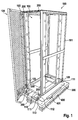
- FIG. 1 shows an exemplary embodiment of a stabilizer assembly for the transport of a cabinet 100.
- the cabinet 100 has a frame 101 of vertical and horizontal struts, wherein on a door side 102 of the frame 101 via three hinges 103, a cabinet door 104 is attached.
- the cabinet door 104 is thus between an open position in which it is pivoted from the door side 102 (as shown), and a closed position in which it rests against the door side 102 (see FIGS. 6 and 7 ), pivotable back and forth.
- the form-fitting pieces 200 are for this purpose in particular attached to a vertical profile side of the horizontal struts of the door 102, for example screwed via a system perforation of regularly spaced mounting receptacles with the profile side.
- a respective form-fitting piece 200 is arranged in each case in one of the four corners of the door side 102, or along the horizontal profiles of the door side 102 upstream of their respective corner.
- the frame 101 further comprises a rectangular bottom frame 109 of four horizontal struts.
- One of the horizontal struts namely the horizontal strut designated by the reference numeral 110, is arranged in the door side 102.
- One of the arranged in the door 102 side horizontal strut 110 opposite further horizontal strut of the bottom frame 109 is disposed in the rear wall side of the frame 101.
- About the horizontal struts 110 in the door 102 and in the Rear wall side are each attached two brackets 111 via a mounting flange 112 which lies in the door 102 side.
- At each of the two brackets 111, in particular on the respective mounting flange 112, one of the form-locking pieces 200 is attached.
- the cabinet 100 is attached to two Gleitboards 300 below the bottom frame 109.
- the bottom frame 109 is placed over the four brackets 111 at a distance from the Gleitboards 300 on a transportable with a forklift transport pallet 400.
- the bottom frame has at each of its four corners formed as L-angle bracket 111, via which the cabinet is attached to one of four Gleitboards.
- the distance under which the bottom frame 109 is attached to the slide boards 300 corresponds to a vertical dimension of a cabinet base.
- the brackets 111 are fixed to a vertical side of the floor frame 109 and extending away from the cabinet 100 with their tread flange 113, so that a tread side of the floor frame 109 for mounting a cabinet base on the tread side is completely exposed.
- the transport pallet 400 has an enclosure 401, which surrounds the Gleitboards 300 and thus keeps the control cabinet 100 on the transport pallet 400 in the horizontal direction or in the plane of the footprint of the transport pallet 400 immovably with tilted pallet. As in FIG. 2 is shown, this particular allows for the transport of the cabinet with a forklift 500 that the cabinet with its usual installations (mounting plate, etc.) can be tilted up to an edge height of about 20 cm, without thereby displaced on the transport pallet 400. Due to the engaging in the form-fitting receptacles 105 form-fitting 200, can be counteracted in tilting the cabinet 100 in the closed position of the cabinet door 104 twisting of the frame 101.
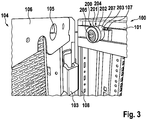
- FIG. 2 and 3 is a first form-fitting 200 shown in a mounting situation on the roof frame of a control cabinet 100.
- the profile struts of the roof frame have a in the closed position of the cabinet door 104 of the cabinet door 104 facing support 107 on which the interlocking piece 200 rests with a projection 207 and is thus aligned in the vertical direction relative to the frame 101.
- the cabinet door 104 has on its outer periphery a U-Umkantung 106, which is folded over from the door leaf of the cabinet door 104 to the inside of the cabinet door 104.
- a positive connection receptacle 105 is formed in the form of a circular opening, in which the interlocking piece 200 engages with its free end 201 in the closed position of the cabinet door 104.
- the free end 201 passes over an undercut 202 in a shaft-shaped portion 203 of the form-fitting 200 over.
- the projection 207 extends beyond a bearing surface of the shaft 203, via which the shaft 203 rests against a vertical profile side of the frame 101, in particular of the roof frame.
- the form-fitting piece 200 is embodied in two parts and, in addition to a body 204 having the free end 201, the undercut 202 and the shank 203, a fastening means 205 in the form of a screw bolt, via which the body 204 can be screwed to the frame 101.
- the frame 101 may for this purpose in particular have an arrangement of regularly spaced mounting receptacles. For example, a cage nut may be inserted into one of the fastening receptacles for the screw connection.
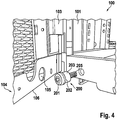
- FIGS. 4 and 5 a further embodiment of a form-fitting piece 200 is shown, which is screwed in the region of a bottom frame of the frame 101 in the corner region of the bottom frame.
- Analogous to that in the Figures 3 and 4 also shown the form-fitting 200 according to the FIGS. 4 and 5 a free end 201 with a start-up contour, which merges via an undercut 202 into a shaft 203.
- the fastening means is integrally formed integrally with the shank 203, concentric with the shank 203, and may in particular be designed in the manner of a threaded bolt.
- the positive connection 105 is analogous to those in Figures 3 and 4 Shaped receptacles shown in turn formed as a circular breakthrough in a U-Umkantung 106 on the outer periphery of a cabinet door 104.
- the free end 201 Concentric with the threaded bolt 205, the free end 201 has a tool holder, for example a hexagon socket.
- the hexagon socket can be identical to the hexagon of the fastener 205 of the in the Figures 2 and 3 be formed shown two-part embodiment.
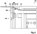
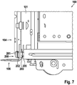
- FIGS. 6 and 7 each show a cabinet 100, in which the cabinet door 104 is disposed in the closed position While the FIG. 6 shows the cabinet 100 in the roof frame is in the FIG. 7 the control cabinet is shown in the area of the floor frame.
- the interlock 200 extends with its free end 201 through a vertical flange of the U-Umkantung 106 therethrough, at least so far that the vertical flange of the U-Umkantung is engaged behind by the undercut 202 of the form-fitting.
- the outer diameter of the interlocking piece 200 may be less than the inner diameter of the positive locking receptacle 105 (see FIGS. 2 to 5 ), so that the stabilization arrangement under load of the frame, such as when tilting the cabinet, as in FIG. 12 is shown, a certain maximum distortion of the frame 101 allows before further connection on further loading of the frame 101 due to the recorded in the form-fitting receptacles 105 form-fitting 200 is prevented.
- FIGS. 8 and 9 a first embodiment of the form-fitting 200 is shown.
- the form-fitting piece 200 has a free end 201, which merges via an undercut 202 into a shaft 203.
- the free end 201, the undercut 202 and the shaft 203 form a body 204 which has an eccentric through bore 206 eccentric to the axis of symmetry of the interlocking fitment 200.
- a projection 207 extends, as with reference to Figures 2 and 3 shown embodiment on a corresponding horizontal support of the frame comes to rest in order to prepare the interlock 200 in the vertical orientation.
- An attachment means 205 in the form of a threaded bolt is provided to extend through the throughbore 206 into a frame of a cabinet, where the threaded bolt 205 may, for example, be screwed into a cage nut and thus secure the body 204 to the frame.
- FIGS. 10 and 11 show a further embodiment of a form-fitting 200, which deviates from that in the FIGS. 8 and 9 shown form-fitting 200 is formed in particular in one piece.
- the free end 201 is provided with a start-up contour, which should facilitate the pivoting of the cabinet door in the closed position, for example, if due to manufacturing tolerances, the positive connection receptacle on the inside of the door and the form-fitting 200 are not exactly aligned with each other at their meeting.
- the free end 201 in turn via an undercut 202 in a shaft-shaped portion 203 via. Concentric with the shaft-shaped portion 203, a threaded bolt 205 is formed on a support side of the shaft 203, via which the interlocking piece 200 can be brought to a frame for conditioning.
Landscapes
- Engineering & Computer Science (AREA)
- Power Engineering (AREA)
- Microelectronics & Electronic Packaging (AREA)
- Manufacturing & Machinery (AREA)
- Mechanical Engineering (AREA)
- Patch Boards (AREA)
- Assembled Shelves (AREA)
Priority Applications (2)
| Application Number | Priority Date | Filing Date | Title |
|---|---|---|---|
| EP17198430.5A EP3477802B1 (fr) | 2017-10-26 | 2017-10-26 | Dispositif de stabilisation pour le transport d'une armoire de commande |
| US16/129,987 US10765025B2 (en) | 2017-10-26 | 2018-09-13 | Stabilizing arrangement for transporting a switch cabinet |
Applications Claiming Priority (1)
| Application Number | Priority Date | Filing Date | Title |
|---|---|---|---|
| EP17198430.5A EP3477802B1 (fr) | 2017-10-26 | 2017-10-26 | Dispositif de stabilisation pour le transport d'une armoire de commande |
Publications (2)
| Publication Number | Publication Date |
|---|---|
| EP3477802A1 true EP3477802A1 (fr) | 2019-05-01 |
| EP3477802B1 EP3477802B1 (fr) | 2022-01-12 |
Family
ID=60186113
Family Applications (1)
| Application Number | Title | Priority Date | Filing Date |
|---|---|---|---|
| EP17198430.5A Active EP3477802B1 (fr) | 2017-10-26 | 2017-10-26 | Dispositif de stabilisation pour le transport d'une armoire de commande |
Country Status (2)
| Country | Link |
|---|---|
| US (1) | US10765025B2 (fr) |
| EP (1) | EP3477802B1 (fr) |
Cited By (1)
| Publication number | Priority date | Publication date | Assignee | Title |
|---|---|---|---|---|
| CN110430711A (zh) * | 2019-07-30 | 2019-11-08 | 深圳日海智能设备有限公司 | 一种服务器机柜 |
Families Citing this family (10)
| Publication number | Priority date | Publication date | Assignee | Title |
|---|---|---|---|---|
| US11167908B2 (en) * | 2018-11-28 | 2021-11-09 | Doron Moshe | Securing mechanism for casing for transporting communications computers and electronics racks |
| IL263352B2 (en) * | 2018-11-28 | 2023-07-01 | Moshe Doron | Locking mechanism for the case for transporting communication cabinets |
| EP3736925A1 (fr) * | 2019-05-09 | 2020-11-11 | Blumenbecker Automatisierungstechnik GmbH | Pince de transport pour portes d'armoires électriques |
| USD926708S1 (en) * | 2019-10-01 | 2021-08-03 | Rittal Gmbh & Co. Kg | Portion of a switchboard for electric connections |
| US11164146B2 (en) | 2019-11-12 | 2021-11-02 | Dell Products L.P. | Inventory identification |
| US11388836B2 (en) * | 2020-01-15 | 2022-07-12 | Dell Products L.P. | Plastic tote |
| US11582874B2 (en) | 2020-01-15 | 2023-02-14 | Dell Products L.P. | Interlocking transportation totes |
| JP7462519B2 (ja) | 2020-08-28 | 2024-04-05 | 河村電器産業株式会社 | 分電盤の機器取付レール |
| CN112660216A (zh) * | 2020-12-25 | 2021-04-16 | 青岛益和电气集团股份有限公司 | 一种手车承载输送装置 |
| CN116667181B (zh) * | 2023-08-01 | 2023-09-22 | 山东东辰节能电力设备有限公司 | 一种新能源储能电站用快装折叠式开关柜 |
Citations (6)
| Publication number | Priority date | Publication date | Assignee | Title |
|---|---|---|---|---|
| DE19615430C1 (de) | 1996-04-19 | 1997-08-14 | Loh Kg Rittal Werk | Schaltschrank mit Rahmengestell und Montageplatte |
| DE19939614C1 (de) * | 1999-08-20 | 2001-09-27 | Driescher Eltech Werk | Druckfester Schaltschrank |
| DE10202845C1 (de) | 2002-01-24 | 2003-08-14 | Rittal Gmbh & Co Kg | Erdbebensicherer Schaltschrank mit Rahmengestell |
| US20110260591A1 (en) * | 2010-04-21 | 2011-10-27 | Hon Hai Precision Industry Co., Ltd. | Server assembly with multi-funtional fixing frame |
| US20140097734A1 (en) * | 2012-10-10 | 2014-04-10 | Central Electric Manufacturing Company | Arc-resistant switchgear enclosure with door latch mechanism |
| CN204425828U (zh) | 2015-01-13 | 2015-06-24 | 苏州叶氏钣金科技有限公司 | 机柜 |
Family Cites Families (2)
| Publication number | Priority date | Publication date | Assignee | Title |
|---|---|---|---|---|
| US5542720A (en) * | 1995-06-26 | 1996-08-06 | W&F Manufacturing, Inc. | Multipoint lock assembly for a sliding door |
| US9297181B2 (en) * | 2011-05-11 | 2016-03-29 | Mario Gasparetto | Arc proof door assembly |
-
2017
- 2017-10-26 EP EP17198430.5A patent/EP3477802B1/fr active Active
-
2018
- 2018-09-13 US US16/129,987 patent/US10765025B2/en active Active
Patent Citations (6)
| Publication number | Priority date | Publication date | Assignee | Title |
|---|---|---|---|---|
| DE19615430C1 (de) | 1996-04-19 | 1997-08-14 | Loh Kg Rittal Werk | Schaltschrank mit Rahmengestell und Montageplatte |
| DE19939614C1 (de) * | 1999-08-20 | 2001-09-27 | Driescher Eltech Werk | Druckfester Schaltschrank |
| DE10202845C1 (de) | 2002-01-24 | 2003-08-14 | Rittal Gmbh & Co Kg | Erdbebensicherer Schaltschrank mit Rahmengestell |
| US20110260591A1 (en) * | 2010-04-21 | 2011-10-27 | Hon Hai Precision Industry Co., Ltd. | Server assembly with multi-funtional fixing frame |
| US20140097734A1 (en) * | 2012-10-10 | 2014-04-10 | Central Electric Manufacturing Company | Arc-resistant switchgear enclosure with door latch mechanism |
| CN204425828U (zh) | 2015-01-13 | 2015-06-24 | 苏州叶氏钣金科技有限公司 | 机柜 |
Cited By (2)
| Publication number | Priority date | Publication date | Assignee | Title |
|---|---|---|---|---|
| CN110430711A (zh) * | 2019-07-30 | 2019-11-08 | 深圳日海智能设备有限公司 | 一种服务器机柜 |
| CN110430711B (zh) * | 2019-07-30 | 2024-01-30 | 深圳日海智能设备有限公司 | 一种服务器机柜 |
Also Published As
| Publication number | Publication date |
|---|---|
| US20190132976A1 (en) | 2019-05-02 |
| US10765025B2 (en) | 2020-09-01 |
| EP3477802B1 (fr) | 2022-01-12 |
Similar Documents
| Publication | Publication Date | Title |
|---|---|---|
| EP3477802B1 (fr) | Dispositif de stabilisation pour le transport d'une armoire de commande | |
| EP2059145B1 (fr) | Tiroir | |
| EP3504391B1 (fr) | Ensemble charnière pour un boitier d'armoire électrique et un boitier d'armoire électrique correspondant | |
| EP2065990B1 (fr) | Armoire électrique | |
| EP3401477B1 (fr) | Meuble | |
| DE102012017948B3 (de) | Verfahren und Anordnung zum Befestigen eines Pfostens an einer Rahmenleiste eines Fensters oder einer Türe mittels eines Pfostenverbinders | |
| WO2018192607A1 (fr) | Ensemble plaque de montage pour armoire de commande | |
| DE202022002815U1 (de) | Verbesserte Inspektionsklappe | |
| DE202009001986U1 (de) | Bordwandverschluss an einem Nutzfahrzeugaufbau | |
| EP0919686B1 (fr) | Penture de porte ou de fenêtre | |
| EP3607624B1 (fr) | Ensemble comprenant un socle et un châssis pour armoire électrique ainsi qu'une rangée d'armoires électriques | |
| DE29517682U1 (de) | Schaltschrank für elektrische Anlagen | |
| DE4321752C1 (de) | Scharnierteil-Wandungs-Verbund | |
| EP0164381A1 (fr) | Charniere pour battant pouvant pivoter, a choix, autour de deux axes | |
| EP1516562B1 (fr) | Dispositif pour regler l'inclinaison d'un tiroir | |
| EP0510346B1 (fr) | Ferrure pour la fixation d'un panneau frontal | |
| DE102007012118B4 (de) | Einstellpuffer für Kraftfahrzeuge | |
| DE102014109970B4 (de) | Gehäuse | |
| EP3556977B1 (fr) | Élément de cadre pour un cadre de meuble et meuble | |
| DE20009019U1 (de) | Vorrichtung zum Befestigen eines Hubwerkes an einem Kraftfahrzeug | |
| DE2456508A1 (de) | Kippriegellager fuer ein fenster, eine tuer o. dgl. | |
| EP3578416B1 (fr) | Dispositif de sécurisation du chargement | |
| DE102019103075B3 (de) | Schaltschrank mit einem Rahmengestell und einem daran festgelegten Seitenwandelement | |
| DE29723545U1 (de) | Befestigungsvorrichtung | |
| DE29817033U1 (de) | Fallenverschluß |
Legal Events
| Date | Code | Title | Description |
|---|---|---|---|
| PUAI | Public reference made under article 153(3) epc to a published international application that has entered the european phase |
Free format text: ORIGINAL CODE: 0009012 |
|
| STAA | Information on the status of an ep patent application or granted ep patent |
Free format text: STATUS: THE APPLICATION HAS BEEN PUBLISHED |
|
| AK | Designated contracting states |
Kind code of ref document: A1 Designated state(s): AL AT BE BG CH CY CZ DE DK EE ES FI FR GB GR HR HU IE IS IT LI LT LU LV MC MK MT NL NO PL PT RO RS SE SI SK SM TR |
|
| AX | Request for extension of the european patent |
Extension state: BA ME |
|
| STAA | Information on the status of an ep patent application or granted ep patent |
Free format text: STATUS: REQUEST FOR EXAMINATION WAS MADE |
|
| 17P | Request for examination filed |
Effective date: 20191029 |
|
| RBV | Designated contracting states (corrected) |
Designated state(s): AL AT BE BG CH CY CZ DE DK EE ES FI FR GB GR HR HU IE IS IT LI LT LU LV MC MK MT NL NO PL PT RO RS SE SI SK SM TR |
|
| STAA | Information on the status of an ep patent application or granted ep patent |
Free format text: STATUS: EXAMINATION IS IN PROGRESS |
|
| 17Q | First examination report despatched |
Effective date: 20200824 |
|
| GRAP | Despatch of communication of intention to grant a patent |
Free format text: ORIGINAL CODE: EPIDOSNIGR1 |
|
| STAA | Information on the status of an ep patent application or granted ep patent |
Free format text: STATUS: GRANT OF PATENT IS INTENDED |
|
| INTG | Intention to grant announced |
Effective date: 20210930 |
|
| GRAS | Grant fee paid |
Free format text: ORIGINAL CODE: EPIDOSNIGR3 |
|
| GRAA | (expected) grant |
Free format text: ORIGINAL CODE: 0009210 |
|
| STAA | Information on the status of an ep patent application or granted ep patent |
Free format text: STATUS: THE PATENT HAS BEEN GRANTED |
|
| AK | Designated contracting states |
Kind code of ref document: B1 Designated state(s): AL AT BE BG CH CY CZ DE DK EE ES FI FR GB GR HR HU IE IS IT LI LT LU LV MC MK MT NL NO PL PT RO RS SE SI SK SM TR |
|
| REG | Reference to a national code |
Ref country code: GB Ref legal event code: FG4D Free format text: NOT ENGLISH |
|
| REG | Reference to a national code |
Ref country code: CH Ref legal event code: EP |
|
| REG | Reference to a national code |
Ref country code: DE Ref legal event code: R096 Ref document number: 502017012434 Country of ref document: DE |
|
| REG | Reference to a national code |
Ref country code: IE Ref legal event code: FG4D Free format text: LANGUAGE OF EP DOCUMENT: GERMAN |
|
| REG | Reference to a national code |
Ref country code: AT Ref legal event code: REF Ref document number: 1463004 Country of ref document: AT Kind code of ref document: T Effective date: 20220215 |
|
| REG | Reference to a national code |
Ref country code: LT Ref legal event code: MG9D |
|
| REG | Reference to a national code |
Ref country code: NL Ref legal event code: MP Effective date: 20220112 |
|
| PG25 | Lapsed in a contracting state [announced via postgrant information from national office to epo] |
Ref country code: NL Free format text: LAPSE BECAUSE OF FAILURE TO SUBMIT A TRANSLATION OF THE DESCRIPTION OR TO PAY THE FEE WITHIN THE PRESCRIBED TIME-LIMIT Effective date: 20220112 |
|
| PG25 | Lapsed in a contracting state [announced via postgrant information from national office to epo] |
Ref country code: SE Free format text: LAPSE BECAUSE OF FAILURE TO SUBMIT A TRANSLATION OF THE DESCRIPTION OR TO PAY THE FEE WITHIN THE PRESCRIBED TIME-LIMIT Effective date: 20220112 Ref country code: RS Free format text: LAPSE BECAUSE OF FAILURE TO SUBMIT A TRANSLATION OF THE DESCRIPTION OR TO PAY THE FEE WITHIN THE PRESCRIBED TIME-LIMIT Effective date: 20220112 Ref country code: PT Free format text: LAPSE BECAUSE OF FAILURE TO SUBMIT A TRANSLATION OF THE DESCRIPTION OR TO PAY THE FEE WITHIN THE PRESCRIBED TIME-LIMIT Effective date: 20220512 Ref country code: NO Free format text: LAPSE BECAUSE OF FAILURE TO SUBMIT A TRANSLATION OF THE DESCRIPTION OR TO PAY THE FEE WITHIN THE PRESCRIBED TIME-LIMIT Effective date: 20220412 Ref country code: LT Free format text: LAPSE BECAUSE OF FAILURE TO SUBMIT A TRANSLATION OF THE DESCRIPTION OR TO PAY THE FEE WITHIN THE PRESCRIBED TIME-LIMIT Effective date: 20220112 Ref country code: HR Free format text: LAPSE BECAUSE OF FAILURE TO SUBMIT A TRANSLATION OF THE DESCRIPTION OR TO PAY THE FEE WITHIN THE PRESCRIBED TIME-LIMIT Effective date: 20220112 Ref country code: ES Free format text: LAPSE BECAUSE OF FAILURE TO SUBMIT A TRANSLATION OF THE DESCRIPTION OR TO PAY THE FEE WITHIN THE PRESCRIBED TIME-LIMIT Effective date: 20220112 Ref country code: BG Free format text: LAPSE BECAUSE OF FAILURE TO SUBMIT A TRANSLATION OF THE DESCRIPTION OR TO PAY THE FEE WITHIN THE PRESCRIBED TIME-LIMIT Effective date: 20220412 |
|
| PG25 | Lapsed in a contracting state [announced via postgrant information from national office to epo] |
Ref country code: PL Free format text: LAPSE BECAUSE OF FAILURE TO SUBMIT A TRANSLATION OF THE DESCRIPTION OR TO PAY THE FEE WITHIN THE PRESCRIBED TIME-LIMIT Effective date: 20220112 Ref country code: LV Free format text: LAPSE BECAUSE OF FAILURE TO SUBMIT A TRANSLATION OF THE DESCRIPTION OR TO PAY THE FEE WITHIN THE PRESCRIBED TIME-LIMIT Effective date: 20220112 Ref country code: GR Free format text: LAPSE BECAUSE OF FAILURE TO SUBMIT A TRANSLATION OF THE DESCRIPTION OR TO PAY THE FEE WITHIN THE PRESCRIBED TIME-LIMIT Effective date: 20220413 Ref country code: FI Free format text: LAPSE BECAUSE OF FAILURE TO SUBMIT A TRANSLATION OF THE DESCRIPTION OR TO PAY THE FEE WITHIN THE PRESCRIBED TIME-LIMIT Effective date: 20220112 |
|
| PG25 | Lapsed in a contracting state [announced via postgrant information from national office to epo] |
Ref country code: IS Free format text: LAPSE BECAUSE OF FAILURE TO SUBMIT A TRANSLATION OF THE DESCRIPTION OR TO PAY THE FEE WITHIN THE PRESCRIBED TIME-LIMIT Effective date: 20220512 |
|
| REG | Reference to a national code |
Ref country code: DE Ref legal event code: R097 Ref document number: 502017012434 Country of ref document: DE |
|
| PG25 | Lapsed in a contracting state [announced via postgrant information from national office to epo] |
Ref country code: SM Free format text: LAPSE BECAUSE OF FAILURE TO SUBMIT A TRANSLATION OF THE DESCRIPTION OR TO PAY THE FEE WITHIN THE PRESCRIBED TIME-LIMIT Effective date: 20220112 Ref country code: SK Free format text: LAPSE BECAUSE OF FAILURE TO SUBMIT A TRANSLATION OF THE DESCRIPTION OR TO PAY THE FEE WITHIN THE PRESCRIBED TIME-LIMIT Effective date: 20220112 Ref country code: RO Free format text: LAPSE BECAUSE OF FAILURE TO SUBMIT A TRANSLATION OF THE DESCRIPTION OR TO PAY THE FEE WITHIN THE PRESCRIBED TIME-LIMIT Effective date: 20220112 Ref country code: EE Free format text: LAPSE BECAUSE OF FAILURE TO SUBMIT A TRANSLATION OF THE DESCRIPTION OR TO PAY THE FEE WITHIN THE PRESCRIBED TIME-LIMIT Effective date: 20220112 Ref country code: DK Free format text: LAPSE BECAUSE OF FAILURE TO SUBMIT A TRANSLATION OF THE DESCRIPTION OR TO PAY THE FEE WITHIN THE PRESCRIBED TIME-LIMIT Effective date: 20220112 Ref country code: CZ Free format text: LAPSE BECAUSE OF FAILURE TO SUBMIT A TRANSLATION OF THE DESCRIPTION OR TO PAY THE FEE WITHIN THE PRESCRIBED TIME-LIMIT Effective date: 20220112 |
|
| PLBE | No opposition filed within time limit |
Free format text: ORIGINAL CODE: 0009261 |
|
| STAA | Information on the status of an ep patent application or granted ep patent |
Free format text: STATUS: NO OPPOSITION FILED WITHIN TIME LIMIT |
|
| PG25 | Lapsed in a contracting state [announced via postgrant information from national office to epo] |
Ref country code: AL Free format text: LAPSE BECAUSE OF FAILURE TO SUBMIT A TRANSLATION OF THE DESCRIPTION OR TO PAY THE FEE WITHIN THE PRESCRIBED TIME-LIMIT Effective date: 20220112 |
|
| 26N | No opposition filed |
Effective date: 20221013 |
|
| PG25 | Lapsed in a contracting state [announced via postgrant information from national office to epo] |
Ref country code: SI Free format text: LAPSE BECAUSE OF FAILURE TO SUBMIT A TRANSLATION OF THE DESCRIPTION OR TO PAY THE FEE WITHIN THE PRESCRIBED TIME-LIMIT Effective date: 20220112 |
|
| PG25 | Lapsed in a contracting state [announced via postgrant information from national office to epo] |
Ref country code: MC Free format text: LAPSE BECAUSE OF FAILURE TO SUBMIT A TRANSLATION OF THE DESCRIPTION OR TO PAY THE FEE WITHIN THE PRESCRIBED TIME-LIMIT Effective date: 20220112 |
|
| REG | Reference to a national code |
Ref country code: CH Ref legal event code: PL |
|
| REG | Reference to a national code |
Ref country code: BE Ref legal event code: MM Effective date: 20221031 |
|
| PG25 | Lapsed in a contracting state [announced via postgrant information from national office to epo] |
Ref country code: LU Free format text: LAPSE BECAUSE OF NON-PAYMENT OF DUE FEES Effective date: 20221026 |
|
| P01 | Opt-out of the competence of the unified patent court (upc) registered |
Effective date: 20230525 |
|
| PG25 | Lapsed in a contracting state [announced via postgrant information from national office to epo] |
Ref country code: LI Free format text: LAPSE BECAUSE OF NON-PAYMENT OF DUE FEES Effective date: 20221031 Ref country code: IT Free format text: LAPSE BECAUSE OF FAILURE TO SUBMIT A TRANSLATION OF THE DESCRIPTION OR TO PAY THE FEE WITHIN THE PRESCRIBED TIME-LIMIT Effective date: 20220112 Ref country code: FR Free format text: LAPSE BECAUSE OF NON-PAYMENT OF DUE FEES Effective date: 20221031 Ref country code: CH Free format text: LAPSE BECAUSE OF NON-PAYMENT OF DUE FEES Effective date: 20221031 |
|
| PG25 | Lapsed in a contracting state [announced via postgrant information from national office to epo] |
Ref country code: BE Free format text: LAPSE BECAUSE OF NON-PAYMENT OF DUE FEES Effective date: 20221031 |
|
| PG25 | Lapsed in a contracting state [announced via postgrant information from national office to epo] |
Ref country code: IE Free format text: LAPSE BECAUSE OF NON-PAYMENT OF DUE FEES Effective date: 20221026 |
|
| REG | Reference to a national code |
Ref country code: AT Ref legal event code: MM01 Ref document number: 1463004 Country of ref document: AT Kind code of ref document: T Effective date: 20221026 |
|
| PG25 | Lapsed in a contracting state [announced via postgrant information from national office to epo] |
Ref country code: AT Free format text: LAPSE BECAUSE OF NON-PAYMENT OF DUE FEES Effective date: 20221026 |
|
| PG25 | Lapsed in a contracting state [announced via postgrant information from national office to epo] |
Ref country code: HU Free format text: LAPSE BECAUSE OF FAILURE TO SUBMIT A TRANSLATION OF THE DESCRIPTION OR TO PAY THE FEE WITHIN THE PRESCRIBED TIME-LIMIT; INVALID AB INITIO Effective date: 20171026 |
|
| PG25 | Lapsed in a contracting state [announced via postgrant information from national office to epo] |
Ref country code: CY Free format text: LAPSE BECAUSE OF FAILURE TO SUBMIT A TRANSLATION OF THE DESCRIPTION OR TO PAY THE FEE WITHIN THE PRESCRIBED TIME-LIMIT Effective date: 20220112 |
|
| PG25 | Lapsed in a contracting state [announced via postgrant information from national office to epo] |
Ref country code: MK Free format text: LAPSE BECAUSE OF FAILURE TO SUBMIT A TRANSLATION OF THE DESCRIPTION OR TO PAY THE FEE WITHIN THE PRESCRIBED TIME-LIMIT Effective date: 20220112 |
|
| PG25 | Lapsed in a contracting state [announced via postgrant information from national office to epo] |
Ref country code: TR Free format text: LAPSE BECAUSE OF FAILURE TO SUBMIT A TRANSLATION OF THE DESCRIPTION OR TO PAY THE FEE WITHIN THE PRESCRIBED TIME-LIMIT Effective date: 20220112 |
|
| PG25 | Lapsed in a contracting state [announced via postgrant information from national office to epo] |
Ref country code: MT Free format text: LAPSE BECAUSE OF FAILURE TO SUBMIT A TRANSLATION OF THE DESCRIPTION OR TO PAY THE FEE WITHIN THE PRESCRIBED TIME-LIMIT Effective date: 20220112 |
|
| PGFP | Annual fee paid to national office [announced via postgrant information from national office to epo] |
Ref country code: DE Payment date: 20251020 Year of fee payment: 9 |
|
| PGFP | Annual fee paid to national office [announced via postgrant information from national office to epo] |
Ref country code: GB Payment date: 20251024 Year of fee payment: 9 |