EP3479059B1 - Procédé et dispositif de mesure de surface optique d'un objet à mesurer - Google Patents
Procédé et dispositif de mesure de surface optique d'un objet à mesurer Download PDFInfo
- Publication number
- EP3479059B1 EP3479059B1 EP18752414.5A EP18752414A EP3479059B1 EP 3479059 B1 EP3479059 B1 EP 3479059B1 EP 18752414 A EP18752414 A EP 18752414A EP 3479059 B1 EP3479059 B1 EP 3479059B1
- Authority
- EP
- European Patent Office
- Prior art keywords
- image
- correction function
- generation device
- brightness
- image pattern
- Prior art date
- Legal status (The legal status is an assumption and is not a legal conclusion. Google has not performed a legal analysis and makes no representation as to the accuracy of the status listed.)
- Active
Links
Images






Classifications
-
- G—PHYSICS
- G01—MEASURING; TESTING
- G01B—MEASURING LENGTH, THICKNESS OR SIMILAR LINEAR DIMENSIONS; MEASURING ANGLES; MEASURING AREAS; MEASURING IRREGULARITIES OF SURFACES OR CONTOURS
- G01B11/00—Measuring arrangements characterised by the use of optical techniques
- G01B11/24—Measuring arrangements characterised by the use of optical techniques for measuring contours or curvatures
- G01B11/25—Measuring arrangements characterised by the use of optical techniques for measuring contours or curvatures by projecting a pattern, e.g. one or more lines, moiré fringes on the object
-
- G—PHYSICS
- G06—COMPUTING OR CALCULATING; COUNTING
- G06T—IMAGE DATA PROCESSING OR GENERATION, IN GENERAL
- G06T5/00—Image enhancement or restoration
- G06T5/80—Geometric correction
-
- H—ELECTRICITY
- H04—ELECTRIC COMMUNICATION TECHNIQUE
- H04N—PICTORIAL COMMUNICATION, e.g. TELEVISION
- H04N23/00—Cameras or camera modules comprising electronic image sensors; Control thereof
- H04N23/70—Circuitry for compensating brightness variation in the scene
- H04N23/71—Circuitry for evaluating the brightness variation
-
- H—ELECTRICITY
- H04—ELECTRIC COMMUNICATION TECHNIQUE
- H04N—PICTORIAL COMMUNICATION, e.g. TELEVISION
- H04N23/00—Cameras or camera modules comprising electronic image sensors; Control thereof
- H04N23/70—Circuitry for compensating brightness variation in the scene
- H04N23/76—Circuitry for compensating brightness variation in the scene by influencing the image signals
Definitions
- the present invention relates to a method for optical surface measurement of a measurement object, wherein an image pattern is displayed using an image generation device and the measurement object is irradiated with this generated image pattern, and wherein the image pattern influenced by the measurement object through reflection, scattering, diffraction and/or transmission is recorded using a detection device. Furthermore, the present invention relates to a device for carrying out the method according to the invention, comprising an image generation device for displaying an image pattern and a detection device for recording the image pattern influenced by the measurement object through reflection, scattering, diffraction or transmission.
- Optical surface measurement often uses image processing methods and corresponding devices in which an image pattern is influenced by the surface and the influenced image pattern is recorded with a camera.
- the image pattern is generated or displayed, for example, using an illuminated screen, a projector or a monitor (display), and the surface to be examined is illuminated with the image pattern.
- the image pattern is influenced by the surface to be examined through reflection, scattering, diffraction or transmission, with the influenced image pattern being recorded with a camera.
- the recorded, influenced image patterns are then evaluated with a computer and measurement results are calculated from them. From the known pattern properties, conclusions can be drawn about the properties of the surface from the image pattern changed or influenced by the surface of the measuring object. Surface properties that are often examined are shape, geometry, errors, defects or texture, etc.
- Well-known measurement methods for surface inspection include the Moiré technique, fringe projection or deflectometry.
- Commercially available projectors (LCD projectors) or computer or television monitors are often used. These are primarily designed for use in the consumer sector and are designed to be viewed with the human eye. The eye unconsciously compensates for many objective errors of a monitor so that a correct image impression is created.
- Cameras record gray or color values so that objective errors, for example of a monitor, are also included in the resulting images.
- a fundamental problem in metrological image processing arises from a temporal change in the brightness of the images, as well as a local change in the brightness of the images. This can lead to artifacts in downstream image processing algorithms that distort the measurement results. Furthermore, this can lead to over- or under-exposure of images or image areas, which can render measurements unusable.
- the brightness deviations can have various causes.
- One problem is that projectors and monitors are designed for the human eye, not for a camera.
- the human eye has a gamma of around 0.3 to 0.5, so the gamma of a monitor is 2.2 (Windows) or 1.8 (Mac).
- Procedures for gamma correction of projectors are known, for example, from the following documents: L.
- Miao et al "An accurate projector gamma correction method for phase-measuring profilometry based on direct optical power detection", VISUAL COMMUNICATIONS AND IMAGE PROCESSING, (2015-10-08), pages 96771D-96771D , M. Dai et al: “Single-shot color fringe projection for three-dimensional shape measurement of objects with discontinuities", APPLIED OPTICS, OPTICAL SOCIETY OF AMERICA, No. 12 (2012-04-20), pages 2062-2069 or T. Hoang et al: “Generic gamma correction for accuracy enhancement in fringe-projection profilometry", OPTICS LETTERS No. 12 (2010-06-15), pages 1992-1994 .
- monitors are designed for a person to view them from the front.
- the present invention is therefore based on the object of designing and developing a method and a device of the type mentioned at the outset in such a way that precise surface measurement is possible in a simple manner.
- the above object is achieved by the features of claim 1.
- the method in question is characterized in that the image generation device and thus the displayed image pattern are adjusted by means of a correction function such that the influenced image pattern recorded by the detection device has an at least substantially constant and/or homogeneous and/or linear brightness in terms of time and/or location.
- the underlying problem can be solved by specifically influencing the temporal and/or spatial brightness of the image pattern generated or displayed by the image generation device.
- the image pattern to be displayed or displayed by the image generation device is adjusted using a correction function. This allows artifacts in the subsequent image processing to be prevented or at least reduced.
- the "image pattern displayed” is the image pattern displayed by the image generation device with which the surface to be examined is irradiated.
- the "influenced image pattern” is the image pattern changed or influenced by the measuring object through reflection, scattering, diffraction or transmission.
- the correction function is used to adjust the gamma correction or the gamma of the image generation device to the gamma correction or the gamma of the detection device.
- image generation devices often have a preset that is unsuitable for the detection device.
- the brightness is set at the factory so that the brightness increases almost linearly from dark to light for the human eye.
- the so-called gamma correction overcompensates the gamma of the human eye (in the range 0.3...0.5) in the image generation device by setting a higher gamma value, which then creates a linear impression of brightness.
- the correction function can be used to correct an inhomogeneous brightness distribution of the image generation device.
- Image generation devices especially monitors, have various types of background lighting: full-surface LED panels, or cold cathode emitters or LEDs on the side edges (edge LED).
- the light is distributed as homogeneously as possible over the monitor surface using light-conducting plastic panels.
- the distribution is not ideal, so there are areas with higher and lower brightness. These brightness differences can be measured, from which a correction function can be determined.
- inhomogeneities in the image pattern caused by lateral viewing rays can be corrected using the correction function.
- Image generation devices in particular monitors, are usually designed in such a way that the view is taken centrally from the front.
- the brightness distribution thus corresponds to an emission to the front.
- this criterion is often not met because lateral viewing rays are also possible due to the triangular arrangement between the image generation device, the measuring object and the detection device resulting from the perspective image.
- the brightness impression recorded by the detection device is therefore also dependent on the direction of view.
- the brightness can be adapted to the - possibly changing - geometric arrangement using a correction function.
- the correction function can be used to adjust the grayscale distribution and/or color distribution of a series of several image patterns displayed one after the other in such a way that the image patterns each have at least essentially the same overall brightness.
- the correction function can correct the brightness of individual images depending on the image content.
- the grayscale can be corrected in such a way that successive images have the same overall brightness.
- the geometric arrangement of the image pattern on or at the image generation device can be adjusted using the correction function.
- the width of a sinusoidal image pattern can be adjusted to the monitor width so that with changing sinusoidal image patterns the overall brightness remains at least almost constant.
- the correction function does not necessarily have to be a mathematical function.
- a lookup table can be used as a correction function. With such a table, input values are mapped to output values, so that corrected output values are generated depending on the input.
- the correction function can also depend on the physical properties of the image generation device.
- the internal gamma of a monitor is usually implemented using a lookup table (LUT) in the firmware.
- the firmware displays gray values on the monitor in such a way that the signal from a computer is offset against values from the LUT in order to achieve a desired impression of brightness.
- a correction function can, for example, be designed as a corrected LUT in the monitor firmware, so that a linear gray value progression is achieved.
- the correction function can depend on the (design-related) brightness distribution of the image generation device.
- the center brightness of the image generation device can be reduced by a location-dependent correction function, for example a correction polynomial or nth degree polynomial.
- the correction function is therefore a mathematical function.
- the images displayed by the image generation device can be brightened at the edge and darkened in the middle, so that the image pattern display has a homogeneous distribution over the surface of the image generation device, for example a monitor.
- the correction function is formed by any mathematical function that supplies modified output values depending on input values and on which a linear function is possibly superimposed.
- the mathematical function can be a spatially and/or temporally variable function.
- a spatial function for example, the brightness deviations within an image displayed on the image generation device can be changed in one or two directions - ie one-dimensionally or two-dimensionally (flat).
- a temporally variable function brightness changes in successive images can be adjusted.
- the correction function can act spatially in one or two axes and/or vary over time.
- the image generation device comprises a projector, a monitor or a screen for displaying the image pattern and/or the detection device comprises a camera for detecting the influenced image pattern.
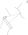
- Fig.1 shows in a schematic view an exemplary structure of a device according to the invention for carrying out the method according to the invention.
- the device comprises an image generating device 1, for example a monitor.
- the image generating device 1 represents an image pattern that is radiated onto a measurement object 2.
- the measurement object 2 can be, for example, a painted motor vehicle whose surface is to be optically measured.
- the device comprises a detection device 3, in particular a camera, whose line of sight 7 is in Fig.1 is shown.
- the detection device 3 records the image pattern on the measurement object 2 influenced by reflection, scattering, diffraction and/or transmission.
- the image generation device 1 comprises a correction unit 4.
- Optical surface measurement such as phase-shifting deflectometry, requires as input data recordings of image patterns displayed on an image generation device 1, such as a monitor, with, for example, sinusoidal stripes that are reflected in the surface of the measurement object 2 to be inspected.
- image generation device 1 such as a monitor
- sinusoidal stripes that are reflected in the surface of the measurement object 2 to be inspected.
- the amplitude and phase position of the displayed sinusoidal pattern is calculated from the recorded, influenced image patterns. The more pronounced the amplitude of the sinusoidal oscillation in the recorded image patterns, the more stable the results of the calculations; a weak signal leads to increased measurement noise.
- a weak signal can be optimized by changing the recording parameters (including exposure time).
- the recording parameters must be selected in such a way that the dynamic range of camera 3 is not exceeded.
- Cameras 3 usually deliver Gray values in the range of 0-255 gray levels. Under no circumstances may the value of 255 be exceeded within the area to be evaluated. This oversaturation would result in the sine wave being cut off and its phase position no longer being able to be clearly determined.
- Fig.3 shows the curvature of the door cutout Fig.2 with the marked second area 6 from Fig.2 At this point the brightness drops significantly compared to the rest of the area.
- the recording situation is optimized in such a way that the recorded, influenced image pattern has a more homogeneous brightness distribution.
- the exposure time can be increased without the risk of oversaturation, thereby increasing the recorded contrast at the corners of the monitor.
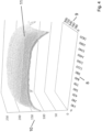
- Fig.4 shows the grayscale of a monitor 1 depending on the position on the monitor 1.
- a monitor 1 with 1900 pixels in width 8 and 1080 pixels in height 9 is shown.
- the z-axis 10 of the Fig.4 shows the grayscale 11, which ranges from approximately 110 to 230.
- Monitor 1 is brightest in the middle, while the brightness drops sharply towards the corners.
- a two-dimensional correction polynomial can be determined as a correction function, with which the required factor for each displayed pixel can be calculated.
- the equation of the correction area depends on the type of monitor used. In practice, polynomials up to degree 4 with pronounced symmetry in both directions have proven to be advantageous.
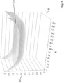
- Fig.5 shows the correction function, namely the correction values in the x and y directions, with which the brightness display of the monitor is corrected. To do this, the gray values of the image pattern that is to be displayed on monitor 1 are multiplied. Usually an ideal sine is displayed.
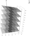
- Fig.6 shows the sinusoidal stripes 12 that extend over the height of the monitor 1 (sinusoidal pattern in x-direction, constant brightness in y-direction). After correction, a sinusoidal curve 13 is obtained that is adjusted over the surface of the monitor 1 with modified gray values as in Fig.7 The maximum brightness in the middle is reduced compared to the corners. The result is an even distribution of brightness of the image pattern across the surface of the monitor 1.
- the signal can be improved at the corners of the monitor without the risk of oversaturation in the center of the monitor.
- the exposure time could even be increased again.
- the viewing angle-dependent brightness distribution could be compensated in a completely analogous manner.
- the azimuth and polar angle at which the camera 3 observes the reflective surface of the measuring object 2 could be used as a correction function.
- a linear function that only depends on the width or height of the monitor 1 could be used as a correction function in a first approximation. Further correction functions, e.g. using the LUT, arise in a completely analogous manner.
- Modulation or contrast image (m, normalized amplitude related to the gray value image: with the amplitude
- the third information channel shows how strong the sinusoidal oscillation is at a certain point and represents the local gloss level of a surface. This representation provides important information about dull spots, such as those that occur due to dirt, scratches and coating defects.
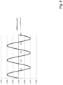
- Fig.9 shows a sinusoidal intensity distribution across the width of a monitor 1 with 1000 pixels.
- the monitor width is an integer multiple of the sinusoidal curve, which means that the mean value of the brightness (in Fig.9 normalized to +/- 1) results in exactly zero across the entire width of monitor 1.
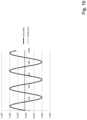
- Fig.10 shows a non-adjusted sinusoidal intensity distribution across the width of a monitor 1.
- the monitor width is now no longer an integer multiple of the sinusoidal curve, which means that the mean value of the brightness across the entire width of monitor 1 is not equal to zero.
- the average brightness contributes to the creation of a different basic brightness in the individual images, particularly on partially reflective or diffusely scattering object surfaces.
- the reflected portion of the light (essentially the original sinusoidal pattern) is additively superimposed by the diffusely scattering portion (essentially the average brightness of the pattern shown).
- Fig. 11 shows four sinusoidal intensity distributions, not adjusted to the monitor width, after reflection on the surface of the measuring object 2 (i.e. in principle the image recorded by the camera 3).
- the sinusoidal intensity distributions are each offset in phase by 90°, as is the case with phase-measuring deflectometry. Due to the principle of phase shifting, different parts of the sinusoidal curve are now shown in the individual images.
- the Fig.10 The effect shown initially leads to different average brightnesses of the individual sinus patterns across the width of the monitor. Due to the overlay with the diffuse portion of the reflection, this leads to an average offset in the brightness for each image pattern. This leads to a modulation of the brightness in the resulting modulation image (formula 3) or amplitude image (formula 4).
- the modulation image or the amplitude image would have a constant brightness.
- Formulas 3 and 4 contain the intensities of the four images I 1 to I 4.
- a constant value (across the width) of monitor 1 would result.
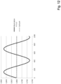
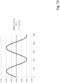
- the lack of adjustment results in a sinusoidal basic modulation ( Fig. 12 for the modulation image, Fig. 13 for the amplitude image), which is caused by the unfavorable choice of the sinusoidal pattern in interaction with the diffusely scattering part of the surface to be measured and leads to a misinterpretation of the measurement data obtained.
- Fig. 14 shows the gamma of a commercially available monitor 1 (solid line).
- a suitably selected correction function (long dashed line) for the brightness display on monitor 1
- a linear brightness impression can be set on the resulting image (short dashed line).
Landscapes
- Engineering & Computer Science (AREA)
- Multimedia (AREA)
- Signal Processing (AREA)
- Physics & Mathematics (AREA)
- General Physics & Mathematics (AREA)
- Computer Vision & Pattern Recognition (AREA)
- Theoretical Computer Science (AREA)
- Length Measuring Devices By Optical Means (AREA)
- Image Processing (AREA)
- Investigating Or Analysing Materials By Optical Means (AREA)
- Geometry (AREA)
- Testing, Inspecting, Measuring Of Stereoscopic Televisions And Televisions (AREA)
Claims (11)
- Procédé de mesure optique d'une surface d'un objet à mesurer (2), dans lequel, avec un dispositif de production d'image (1), qui comprend un projecteur et/ou un moniteur et/ou un écran, représente un motif d'image et l'objet à mesurer est irradié avec de motif d'image produit et dans lequel le motif d'image, influencé par l'objet à mesurer par réflexion, diffusion, diffraction et/ou transmission, est enregistré avec un dispositif d'enregistrement (3), dans lequel, au moyen d'une fonction de correction, le dispositif de production d'image (1) et donc le motif d'image représenté est adapté de sorte que le motif d'image influencé, enregistré par le dispositif d'enregistrement (3) présente, de manière temporelle et/ou localement une luminosité au moins globalement constante et/ou homogène et/ou linéaire,caractérisé en ce que, au moyen de la fonction de correction, une répartition de luminosité inhomogène du dispositif de production d'image (1) est corrigée, de sorte que la représentation du motif d'image présente une répartition homogène sur la surface du dispositif de production d'image,ou en ce que, au moyen de la fonction de correction, la répartition des niveaux de gris et/ou la répartition des couleurs d'une série de plusieurs motifs d'image représentés successivement est adaptée de sorte que les motifs d'images représentés présentent chacun au moins globalement une luminosité totale égale.
- Procédé selon la revendication 1, caractérisé en ce que, au moyen de la fonction de correction, la correction gamma du dispositif de production d'image (1) est adaptée à la correction gamma du dispositif d'enregistrement (3).
- Procédé selon la revendication 1 ou 2, caractérisé en ce que, au moyen de la fonction de correction, une répartition de luminosité inhomogène, due à la conception, du dispositif de production d'image (1), est corrigée.
- Procédé selon l'une des revendications 1 à 3, caractérisé en ce que, au moyen de la fonction de correction, les inhomogénéités provoquées par des rayons visibles latéraux (7), du motif d'image représenté par le dispositif de production d'image (1), sont corrigées.
- Procédé selon l'une des revendications 1 à 4, caractérisé en ce que, au moyen de la fonction de correction, la disposition géométrique du motif d'image représenté est adapté sur ou au niveau du dispositif de production d'image (1).
- Procédé selon l'une des revendications 1 à 5, caractérisé en ce que la fonction de correction utilisée est une table de correspondance.
- Procédé selon l'une des revendications 1 à 6, caractérisé en ce que la fonction de correction utilisée est une fonction mathématique quelconque.
- Procédé selon la revendication 7, caractérisé en ce que, à la fonction de correction, est superposée une fonction linéaire.
- Procédé selon l'une des revendications 1 à 8, caractérisé en ce que la fonction de correction agit dans l'espace dans un ou dans deux axes et/ou en ce que la fonction de correction varie dans le temps.
- Procédé selon l'une des revendications 1 à 9, caractérisé en ce que le dispositif d'enregistrement (3) comprend une caméra.
- Dispositif d'exécution du procédé selon l'une des revendications 1 à 10, comprenant un dispositif de production d'image (1) avec un projecteur et/ou un moniteur et/ou un écran pour al représentation d'un motif d'image et un dispositif d'enregistrement (3) pour le logement du motif d'image influencé par l'objet à mesurer (2) par réflexion, diffusion, diffraction et/ou transmission, dans lequel le dispositif de production d'image (1) comprend une unité de correction (4) qui adapte, par l'intermédiaire d'une fonction de correction le motif d'image représenté, de sorte que le motif d'image influencé enregistré par le dispositif d'enregistrement (3) présente, de manière temporelle et/ou localement, une luminosité au moins globalement constante et/ou homogène et/ou linéaire,
caractérisé en ce que l'unité de correction (4) corrige, au moyen de la fonction de correction, une répartition de luminosité inhomogène du dispositif de production d'image (1) de sorte que la représentation du motif d'image présente une répartition homogène sur la surface du dispositif de production d'image (1) ou en ce que l'unité de correction (4) adapte, au moyen de la fonction de correction, la répartition des niveaux de gris et/ou la répartition des couleurs d'une série de plusieurs motifs d'image représentés successivement de sorte que les motifs d'image représentés présentent chacun au moins globalement une luminosité totale égale.
Applications Claiming Priority (2)
| Application Number | Priority Date | Filing Date | Title |
|---|---|---|---|
| DE102017211377.4A DE102017211377B4 (de) | 2017-07-04 | 2017-07-04 | Verfahren und Vorrichtung zur optischen Oberflächenvermessung eines Messobjektes |
| PCT/DE2018/200050 WO2019007468A1 (fr) | 2017-07-04 | 2018-05-18 | Procédé et dispositif de mesure de surface optique d'un objet à mesurer |
Publications (2)
| Publication Number | Publication Date |
|---|---|
| EP3479059A1 EP3479059A1 (fr) | 2019-05-08 |
| EP3479059B1 true EP3479059B1 (fr) | 2024-08-28 |
Family
ID=63144783
Family Applications (1)
| Application Number | Title | Priority Date | Filing Date |
|---|---|---|---|
| EP18752414.5A Active EP3479059B1 (fr) | 2017-07-04 | 2018-05-18 | Procédé et dispositif de mesure de surface optique d'un objet à mesurer |
Country Status (8)
| Country | Link |
|---|---|
| US (2) | US11125550B2 (fr) |
| EP (1) | EP3479059B1 (fr) |
| JP (1) | JP7016892B2 (fr) |
| KR (1) | KR102398723B1 (fr) |
| CN (1) | CN110832271B (fr) |
| DE (1) | DE102017211377B4 (fr) |
| ES (1) | ES3000508T3 (fr) |
| WO (1) | WO2019007468A1 (fr) |
Families Citing this family (11)
| Publication number | Priority date | Publication date | Assignee | Title |
|---|---|---|---|---|
| KR101955847B1 (ko) * | 2018-01-23 | 2019-03-11 | 한국표준과학연구원 | 위상천이 편향측정법에서 비선형 응답특성을 보상하기 위한 시스템 및 방법 |
| US11328380B2 (en) * | 2018-10-27 | 2022-05-10 | Gilbert Pinter | Machine vision systems, illumination sources for use in machine vision systems, and components for use in the illumination sources |
| JP7310218B2 (ja) * | 2019-03-28 | 2023-07-19 | セイコーエプソン株式会社 | 三次元計測方法、三次元計測装置およびロボットシステム |
| EP4321923A4 (fr) | 2021-08-05 | 2024-10-30 | Samsung Electronics Co., Ltd. | Dispositif de réalité augmentée et procédé de détection du regard d'un utilisateur |
| EP4404142A4 (fr) * | 2021-10-18 | 2026-01-07 | Lightvision Inc | Système de conversion d'image à motif de diffraction et procédé d'interconversion d'image sadp tem virtuelle et d'image temm sadp réelle en utilisant un apprentissage profond |
| KR102582498B1 (ko) * | 2021-10-18 | 2023-09-26 | 라이트비전 주식회사 | 높은 분별력을 가지는 tem sadp 영상 생성 시스템 및 방법 |
| EP4401038A4 (fr) * | 2021-10-18 | 2026-04-01 | Lightvision Inc | Système et procédé pour générer une image de sadp tem avec une aptitude de distinction élevée |
| JP2023105524A (ja) * | 2022-01-19 | 2023-07-31 | 株式会社ソニー・インタラクティブエンタテインメント | 表示制御装置、ヘッドマウントディスプレイ、および表示制御方法 |
| CN115086627B (zh) * | 2022-06-06 | 2023-05-30 | 岚图汽车科技有限公司 | 投影仪控制方法及装置、车辆 |
| CN119554992A (zh) * | 2024-11-12 | 2025-03-04 | 江淮前沿技术协同创新中心 | 基于改进的多曝光图像融合的结构光三维测量方法及系统 |
| CN121298771B (zh) * | 2025-12-12 | 2026-03-20 | 上海帆声图像科技有限公司 | 一种基于余弦拟合与rmse可靠度加权的反斑点调制度估计方法 |
Family Cites Families (5)
| Publication number | Priority date | Publication date | Assignee | Title |
|---|---|---|---|---|
| US6256010B1 (en) * | 1997-06-30 | 2001-07-03 | Industrial Technology Research Institute | Dynamic correction of LCD gamma curve |
| CA2528791A1 (fr) * | 2005-12-01 | 2007-06-01 | Peirong Jia | Methode de mesure tridimensionnelle plein champ |
| CN103292734B (zh) * | 2013-05-27 | 2015-10-28 | 华中科技大学 | 相位测量系统中伽玛值标定方法 |
| CN103983208A (zh) * | 2014-05-09 | 2014-08-13 | 南昌航空大学 | 彩色二进制条纹离焦投影三维测量方法 |
| CN105403172B (zh) * | 2015-10-27 | 2018-07-20 | 华侨大学 | 一种大视场结构光视觉测量中分区域Gamma预校正相位误差补偿方法 |
-
2017
- 2017-07-04 DE DE102017211377.4A patent/DE102017211377B4/de active Active
-
2018
- 2018-05-18 JP JP2019571620A patent/JP7016892B2/ja active Active
- 2018-05-18 KR KR1020207003010A patent/KR102398723B1/ko active Active
- 2018-05-18 WO PCT/DE2018/200050 patent/WO2019007468A1/fr not_active Ceased
- 2018-05-18 EP EP18752414.5A patent/EP3479059B1/fr active Active
- 2018-05-18 US US16/627,161 patent/US11125550B2/en active Active
- 2018-05-18 ES ES18752414T patent/ES3000508T3/es active Active
- 2018-05-18 CN CN201880044995.8A patent/CN110832271B/zh active Active
-
2021
- 2021-07-16 US US17/378,571 patent/US20210364277A1/en not_active Abandoned
Also Published As
| Publication number | Publication date |
|---|---|
| EP3479059A1 (fr) | 2019-05-08 |
| US11125550B2 (en) | 2021-09-21 |
| US20200158498A1 (en) | 2020-05-21 |
| DE102017211377B4 (de) | 2021-01-14 |
| CN110832271A (zh) | 2020-02-21 |
| CN110832271B (zh) | 2022-11-11 |
| ES3000508T3 (en) | 2025-02-28 |
| JP7016892B2 (ja) | 2022-02-07 |
| JP2020527225A (ja) | 2020-09-03 |
| KR20200028406A (ko) | 2020-03-16 |
| DE102017211377A1 (de) | 2019-01-10 |
| WO2019007468A1 (fr) | 2019-01-10 |
| US20210364277A1 (en) | 2021-11-25 |
| KR102398723B1 (ko) | 2022-05-17 |
Similar Documents
| Publication | Publication Date | Title |
|---|---|---|
| EP3479059B1 (fr) | Procédé et dispositif de mesure de surface optique d'un objet à mesurer | |
| EP1784978B1 (fr) | Procede et dispositif pour representer une image numerique sur une surface non triviale d'un point de vue geometrique ou photometrique | |
| EP2188661B1 (fr) | Procédé et dispositif d'éclairage permettant une amplification du contraste optique | |
| EP3557523B1 (fr) | Procédé de génération d'un modèle de correction d'une caméra permettant de corriger une erreur d'image | |
| DE69007399T2 (de) | Methode und Vorrichtung zur Optimierung des Kontrastes und des Sichtwinkels einer Flüssigkristall-Anzeige. | |
| DE3441162C2 (de) | Einrichtung zum Korrigieren von Kontrastverlusten bei angiographischen Bilddarstellungen | |
| EP2277304B1 (fr) | Procédé et dispositif permettant le rendu de couleurs sur des écrans de manière fidèle à un original | |
| DE602004001500T2 (de) | Apparat für dreidimensionale Messungen | |
| DE3422143A1 (de) | Geraet zur wafer-inspektion | |
| DE68911072T2 (de) | Verfahren und Anordnung zur Korrektur von Streustrahlungseffekten in Röntgenbildern. | |
| DE102017102227A1 (de) | Verfahren und Vorrichtung zur automatischen Identifizierung einer interessierenden Stelle in einer Tiefenmessung an einem betrachteten Objekt | |
| DE102011088760A1 (de) | Anzeigevorrichtung | |
| DE102015204640A1 (de) | Verfahren zur Erfassung der Kontrastseh-Fähigkeit | |
| DE102015217173A1 (de) | Kalibriersystem und Inspektionsanlage | |
| DE102011055967B4 (de) | Messverfahren und Vorrichtung zur Durchführung des Messverfahrens | |
| DE102023101395A1 (de) | Verfahren zur Messwertkorrektur bei Messungen eines Partikelvolumenstroms mittels Schattenfotografie | |
| DE102005003226B4 (de) | Verfahren und Einrichtung zur Wiedergabe eines Röntgenbildes | |
| DE102013104710A1 (de) | Verfahren zur lichtabhängigen Grauwertkorrektur | |
| DE102017204302B4 (de) | Vorrichtung zur Abbildung eines Objektes mittels Schattenwurf | |
| EP4249891B1 (fr) | Procédé de correction de valeur de mesure lors de mesures d'un flux volumique de particules à l'aide de photographie d'ombre | |
| DE102018217221A1 (de) | Verfahren zur Dosisreduzierung bei einem Röntgengerät unter Berücksichtigung einer späteren Darstellung; Bildgebungsanlage; Computerprogramm sowie Datenträger | |
| AT410259B (de) | Verfahren zur glarebestimmung und zur glarekorrektur sowie verfahren zur anfertigung eines präparates hiefür | |
| DE112021003168T5 (de) | Einrichtung zur korrektur von kollimatorhalbschatten in einem röntgenbild | |
| DE102015102334A1 (de) | Verfahren zur Korrektur von zweidimensionalen Durchstrahlungsbildern, insbesondere für die dimensionelle Messung mit einer Computertomografiesensorik | |
| DE102008032686A1 (de) | Verfahren zur Verbesserung des Kontrastes von Bildern, insbesondere Grauwertbildern und Vorrichtung zu seiner Durchführung |
Legal Events
| Date | Code | Title | Description |
|---|---|---|---|
| STAA | Information on the status of an ep patent application or granted ep patent |
Free format text: STATUS: UNKNOWN |
|
| STAA | Information on the status of an ep patent application or granted ep patent |
Free format text: STATUS: THE INTERNATIONAL PUBLICATION HAS BEEN MADE |
|
| PUAI | Public reference made under article 153(3) epc to a published international application that has entered the european phase |
Free format text: ORIGINAL CODE: 0009012 |
|
| STAA | Information on the status of an ep patent application or granted ep patent |
Free format text: STATUS: REQUEST FOR EXAMINATION WAS MADE |
|
| 17P | Request for examination filed |
Effective date: 20190131 |
|
| AK | Designated contracting states |
Kind code of ref document: A1 Designated state(s): AL AT BE BG CH CY CZ DE DK EE ES FI FR GB GR HR HU IE IS IT LI LT LU LV MC MK MT NL NO PL PT RO RS SE SI SK SM TR |
|
| AX | Request for extension of the european patent |
Extension state: BA ME |
|
| DAV | Request for validation of the european patent (deleted) | ||
| DAX | Request for extension of the european patent (deleted) | ||
| STAA | Information on the status of an ep patent application or granted ep patent |
Free format text: STATUS: EXAMINATION IS IN PROGRESS |
|
| 17Q | First examination report despatched |
Effective date: 20210610 |
|
| GRAP | Despatch of communication of intention to grant a patent |
Free format text: ORIGINAL CODE: EPIDOSNIGR1 |
|
| STAA | Information on the status of an ep patent application or granted ep patent |
Free format text: STATUS: GRANT OF PATENT IS INTENDED |
|
| INTG | Intention to grant announced |
Effective date: 20240508 |
|
| GRAS | Grant fee paid |
Free format text: ORIGINAL CODE: EPIDOSNIGR3 |
|
| GRAA | (expected) grant |
Free format text: ORIGINAL CODE: 0009210 |
|
| STAA | Information on the status of an ep patent application or granted ep patent |
Free format text: STATUS: THE PATENT HAS BEEN GRANTED |
|
| P01 | Opt-out of the competence of the unified patent court (upc) registered |
Free format text: CASE NUMBER: APP_40846/2024 Effective date: 20240710 |
|
| AK | Designated contracting states |
Kind code of ref document: B1 Designated state(s): AL AT BE BG CH CY CZ DE DK EE ES FI FR GB GR HR HU IE IS IT LI LT LU LV MC MK MT NL NO PL PT RO RS SE SI SK SM TR |
|
| REG | Reference to a national code |
Ref country code: GB Ref legal event code: FG4D Free format text: NOT ENGLISH |
|
| REG | Reference to a national code |
Ref country code: CH Ref legal event code: EP |
|
| REG | Reference to a national code |
Ref country code: DE Ref legal event code: R096 Ref document number: 502018015065 Country of ref document: DE |
|
| REG | Reference to a national code |
Ref country code: IE Ref legal event code: FG4D Free format text: LANGUAGE OF EP DOCUMENT: GERMAN |
|
| REG | Reference to a national code |
Ref country code: LT Ref legal event code: MG9D |
|
| PG25 | Lapsed in a contracting state [announced via postgrant information from national office to epo] |
Ref country code: NO Free format text: LAPSE BECAUSE OF FAILURE TO SUBMIT A TRANSLATION OF THE DESCRIPTION OR TO PAY THE FEE WITHIN THE PRESCRIBED TIME-LIMIT Effective date: 20241128 |
|
| PG25 | Lapsed in a contracting state [announced via postgrant information from national office to epo] |
Ref country code: PT Free format text: LAPSE BECAUSE OF FAILURE TO SUBMIT A TRANSLATION OF THE DESCRIPTION OR TO PAY THE FEE WITHIN THE PRESCRIBED TIME-LIMIT Effective date: 20241230 Ref country code: NL Free format text: LAPSE BECAUSE OF FAILURE TO SUBMIT A TRANSLATION OF THE DESCRIPTION OR TO PAY THE FEE WITHIN THE PRESCRIBED TIME-LIMIT Effective date: 20240828 Ref country code: FI Free format text: LAPSE BECAUSE OF FAILURE TO SUBMIT A TRANSLATION OF THE DESCRIPTION OR TO PAY THE FEE WITHIN THE PRESCRIBED TIME-LIMIT Effective date: 20240828 Ref country code: GR Free format text: LAPSE BECAUSE OF FAILURE TO SUBMIT A TRANSLATION OF THE DESCRIPTION OR TO PAY THE FEE WITHIN THE PRESCRIBED TIME-LIMIT Effective date: 20241129 Ref country code: PL Free format text: LAPSE BECAUSE OF FAILURE TO SUBMIT A TRANSLATION OF THE DESCRIPTION OR TO PAY THE FEE WITHIN THE PRESCRIBED TIME-LIMIT Effective date: 20240828 |
|
| PG25 | Lapsed in a contracting state [announced via postgrant information from national office to epo] |
Ref country code: BG Free format text: LAPSE BECAUSE OF FAILURE TO SUBMIT A TRANSLATION OF THE DESCRIPTION OR TO PAY THE FEE WITHIN THE PRESCRIBED TIME-LIMIT Effective date: 20240828 |
|
| PG25 | Lapsed in a contracting state [announced via postgrant information from national office to epo] |
Ref country code: LV Free format text: LAPSE BECAUSE OF FAILURE TO SUBMIT A TRANSLATION OF THE DESCRIPTION OR TO PAY THE FEE WITHIN THE PRESCRIBED TIME-LIMIT Effective date: 20240828 |
|
| REG | Reference to a national code |
Ref country code: NL Ref legal event code: MP Effective date: 20240828 |
|
| PG25 | Lapsed in a contracting state [announced via postgrant information from national office to epo] |
Ref country code: IS Free format text: LAPSE BECAUSE OF FAILURE TO SUBMIT A TRANSLATION OF THE DESCRIPTION OR TO PAY THE FEE WITHIN THE PRESCRIBED TIME-LIMIT Effective date: 20241228 |
|
| PG25 | Lapsed in a contracting state [announced via postgrant information from national office to epo] |
Ref country code: HR Free format text: LAPSE BECAUSE OF FAILURE TO SUBMIT A TRANSLATION OF THE DESCRIPTION OR TO PAY THE FEE WITHIN THE PRESCRIBED TIME-LIMIT Effective date: 20240828 |
|
| PG25 | Lapsed in a contracting state [announced via postgrant information from national office to epo] |
Ref country code: RS Free format text: LAPSE BECAUSE OF FAILURE TO SUBMIT A TRANSLATION OF THE DESCRIPTION OR TO PAY THE FEE WITHIN THE PRESCRIBED TIME-LIMIT Effective date: 20241128 |
|
| PG25 | Lapsed in a contracting state [announced via postgrant information from national office to epo] |
Ref country code: RS Free format text: LAPSE BECAUSE OF FAILURE TO SUBMIT A TRANSLATION OF THE DESCRIPTION OR TO PAY THE FEE WITHIN THE PRESCRIBED TIME-LIMIT Effective date: 20241128 Ref country code: PT Free format text: LAPSE BECAUSE OF FAILURE TO SUBMIT A TRANSLATION OF THE DESCRIPTION OR TO PAY THE FEE WITHIN THE PRESCRIBED TIME-LIMIT Effective date: 20241230 Ref country code: PL Free format text: LAPSE BECAUSE OF FAILURE TO SUBMIT A TRANSLATION OF THE DESCRIPTION OR TO PAY THE FEE WITHIN THE PRESCRIBED TIME-LIMIT Effective date: 20240828 Ref country code: NO Free format text: LAPSE BECAUSE OF FAILURE TO SUBMIT A TRANSLATION OF THE DESCRIPTION OR TO PAY THE FEE WITHIN THE PRESCRIBED TIME-LIMIT Effective date: 20241128 Ref country code: NL Free format text: LAPSE BECAUSE OF FAILURE TO SUBMIT A TRANSLATION OF THE DESCRIPTION OR TO PAY THE FEE WITHIN THE PRESCRIBED TIME-LIMIT Effective date: 20240828 Ref country code: LV Free format text: LAPSE BECAUSE OF FAILURE TO SUBMIT A TRANSLATION OF THE DESCRIPTION OR TO PAY THE FEE WITHIN THE PRESCRIBED TIME-LIMIT Effective date: 20240828 Ref country code: IS Free format text: LAPSE BECAUSE OF FAILURE TO SUBMIT A TRANSLATION OF THE DESCRIPTION OR TO PAY THE FEE WITHIN THE PRESCRIBED TIME-LIMIT Effective date: 20241228 Ref country code: HR Free format text: LAPSE BECAUSE OF FAILURE TO SUBMIT A TRANSLATION OF THE DESCRIPTION OR TO PAY THE FEE WITHIN THE PRESCRIBED TIME-LIMIT Effective date: 20240828 Ref country code: GR Free format text: LAPSE BECAUSE OF FAILURE TO SUBMIT A TRANSLATION OF THE DESCRIPTION OR TO PAY THE FEE WITHIN THE PRESCRIBED TIME-LIMIT Effective date: 20241129 Ref country code: FI Free format text: LAPSE BECAUSE OF FAILURE TO SUBMIT A TRANSLATION OF THE DESCRIPTION OR TO PAY THE FEE WITHIN THE PRESCRIBED TIME-LIMIT Effective date: 20240828 Ref country code: BG Free format text: LAPSE BECAUSE OF FAILURE TO SUBMIT A TRANSLATION OF THE DESCRIPTION OR TO PAY THE FEE WITHIN THE PRESCRIBED TIME-LIMIT Effective date: 20240828 |
|
| REG | Reference to a national code |
Ref country code: ES Ref legal event code: FG2A Ref document number: 3000508 Country of ref document: ES Kind code of ref document: T3 Effective date: 20250228 |
|
| PG25 | Lapsed in a contracting state [announced via postgrant information from national office to epo] |
Ref country code: SM Free format text: LAPSE BECAUSE OF FAILURE TO SUBMIT A TRANSLATION OF THE DESCRIPTION OR TO PAY THE FEE WITHIN THE PRESCRIBED TIME-LIMIT Effective date: 20240828 Ref country code: RO Free format text: LAPSE BECAUSE OF FAILURE TO SUBMIT A TRANSLATION OF THE DESCRIPTION OR TO PAY THE FEE WITHIN THE PRESCRIBED TIME-LIMIT Effective date: 20240828 Ref country code: DK Free format text: LAPSE BECAUSE OF FAILURE TO SUBMIT A TRANSLATION OF THE DESCRIPTION OR TO PAY THE FEE WITHIN THE PRESCRIBED TIME-LIMIT Effective date: 20240828 |
|
| PG25 | Lapsed in a contracting state [announced via postgrant information from national office to epo] |
Ref country code: EE Free format text: LAPSE BECAUSE OF FAILURE TO SUBMIT A TRANSLATION OF THE DESCRIPTION OR TO PAY THE FEE WITHIN THE PRESCRIBED TIME-LIMIT Effective date: 20240828 |
|
| PG25 | Lapsed in a contracting state [announced via postgrant information from national office to epo] |
Ref country code: CZ Free format text: LAPSE BECAUSE OF FAILURE TO SUBMIT A TRANSLATION OF THE DESCRIPTION OR TO PAY THE FEE WITHIN THE PRESCRIBED TIME-LIMIT Effective date: 20240828 |
|
| PG25 | Lapsed in a contracting state [announced via postgrant information from national office to epo] |
Ref country code: SK Free format text: LAPSE BECAUSE OF FAILURE TO SUBMIT A TRANSLATION OF THE DESCRIPTION OR TO PAY THE FEE WITHIN THE PRESCRIBED TIME-LIMIT Effective date: 20240828 |
|
| REG | Reference to a national code |
Ref country code: DE Ref legal event code: R097 Ref document number: 502018015065 Country of ref document: DE |
|
| PLBE | No opposition filed within time limit |
Free format text: ORIGINAL CODE: 0009261 |
|
| STAA | Information on the status of an ep patent application or granted ep patent |
Free format text: STATUS: NO OPPOSITION FILED WITHIN TIME LIMIT |
|
| PGFP | Annual fee paid to national office [announced via postgrant information from national office to epo] |
Ref country code: GB Payment date: 20250522 Year of fee payment: 8 Ref country code: ES Payment date: 20250616 Year of fee payment: 8 |
|
| PGFP | Annual fee paid to national office [announced via postgrant information from national office to epo] |
Ref country code: IT Payment date: 20250530 Year of fee payment: 8 |
|
| PGFP | Annual fee paid to national office [announced via postgrant information from national office to epo] |
Ref country code: FR Payment date: 20250521 Year of fee payment: 8 |
|
| 26N | No opposition filed |
Effective date: 20250530 |
|
| PG25 | Lapsed in a contracting state [announced via postgrant information from national office to epo] |
Ref country code: SE Free format text: LAPSE BECAUSE OF FAILURE TO SUBMIT A TRANSLATION OF THE DESCRIPTION OR TO PAY THE FEE WITHIN THE PRESCRIBED TIME-LIMIT Effective date: 20240828 |
|
| PGFP | Annual fee paid to national office [announced via postgrant information from national office to epo] |
Ref country code: DE Payment date: 20250730 Year of fee payment: 8 |
|
| REG | Reference to a national code |
Ref country code: CH Ref legal event code: H13 Free format text: ST27 STATUS EVENT CODE: U-0-0-H10-H13 (AS PROVIDED BY THE NATIONAL OFFICE) Effective date: 20251223 |
|
| PG25 | Lapsed in a contracting state [announced via postgrant information from national office to epo] |
Ref country code: LU Free format text: LAPSE BECAUSE OF NON-PAYMENT OF DUE FEES Effective date: 20250518 |
|
| PG25 | Lapsed in a contracting state [announced via postgrant information from national office to epo] |
Ref country code: CH Free format text: LAPSE BECAUSE OF NON-PAYMENT OF DUE FEES Effective date: 20250531 |
|
| REG | Reference to a national code |
Ref country code: BE Ref legal event code: MM Effective date: 20250531 |
|
| PG25 | Lapsed in a contracting state [announced via postgrant information from national office to epo] |
Ref country code: MC Free format text: LAPSE BECAUSE OF FAILURE TO SUBMIT A TRANSLATION OF THE DESCRIPTION OR TO PAY THE FEE WITHIN THE PRESCRIBED TIME-LIMIT Effective date: 20240828 |
|
| PG25 | Lapsed in a contracting state [announced via postgrant information from national office to epo] |
Ref country code: IE Free format text: LAPSE BECAUSE OF NON-PAYMENT OF DUE FEES Effective date: 20250518 |
|
| PG25 | Lapsed in a contracting state [announced via postgrant information from national office to epo] |
Ref country code: BE Free format text: LAPSE BECAUSE OF NON-PAYMENT OF DUE FEES Effective date: 20250531 |